WO2017141633A1 - Dispositif de visualisation pour véhicules - Google Patents
Dispositif de visualisation pour véhicules Download PDFInfo
- Publication number
- WO2017141633A1 WO2017141633A1 PCT/JP2017/002166 JP2017002166W WO2017141633A1 WO 2017141633 A1 WO2017141633 A1 WO 2017141633A1 JP 2017002166 W JP2017002166 W JP 2017002166W WO 2017141633 A1 WO2017141633 A1 WO 2017141633A1
- Authority
- WO
- WIPO (PCT)
- Prior art keywords
- mirror
- wall
- vehicle
- terminal
- visual recognition
- Prior art date
- Legal status (The legal status is an assumption and is not a legal conclusion. Google has not performed a legal analysis and makes no representation as to the accuracy of the status listed.)
- Ceased
Links
Images
Classifications
-
- B—PERFORMING OPERATIONS; TRANSPORTING
- B60—VEHICLES IN GENERAL
- B60R—VEHICLES, VEHICLE FITTINGS, OR VEHICLE PARTS, NOT OTHERWISE PROVIDED FOR
- B60R1/00—Optical viewing arrangements; Real-time viewing arrangements for drivers or passengers using optical image capturing systems, e.g. cameras or video systems specially adapted for use in or on vehicles
- B60R1/02—Rear-view mirror arrangements
- B60R1/06—Rear-view mirror arrangements mounted on vehicle exterior
Definitions
- the present invention relates to a vehicle visual recognition device in which a visual recognition unit assists visual recognition of a vehicle occupant.
- the mirror angle adjustment mechanism supports the door mirror unit, and the door mirror unit is provided with a display forming unit and an LED, and the LED illuminates the display forming unit.
- the present invention has been made in view of the above facts, and an object of the present invention is to obtain a vehicle visual recognition device that can eliminate the need to route a harness between the visual recognition part and the terminal part side.
- the vehicular visual recognition device is made tiltable, assists the visual recognition of a vehicle occupant, and includes a visual recognition part provided with a sliding part, and the sliding part when the visual recognition part is tilted.
- the moving part is slid and a terminal part electrically connected to the sliding part is provided.
- the visual recognition part can be tilted, and the visual recognition part assists visual recognition of the vehicle occupant.
- the sliding part is provided in the visual recognition part, and when the visual recognition part is tilted, the sliding part slides on the terminal part, and the sliding part is electrically connected to the terminal part.
- the vehicle visual recognition device is the vehicle visual recognition device according to the first aspect, wherein the terminal portion supports the visual recognition portion so as to be tiltable.
- the terminal portion supports the visual recognition portion so as to be tiltable. Therefore, it is possible to eliminate the necessity of providing a portion where the sliding portion is slid on the terminal portion separately from the portion where the visual recognition portion is tiltably supported.
- a vehicle visual recognition device is the vehicle visual recognition device according to the first or second aspect, in which the wiring provided integrally with the visual recognition portion and electrically connected to the sliding portion is provided. Prepare.
- the wiring is electrically connected to the sliding portion, and the wiring is provided integrally with the visual recognition portion.
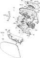
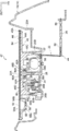
- FIG. 1 shows an exploded perspective view of a door mirror device 10 as a vehicle visual recognition device according to an embodiment of the present invention as seen from the vehicle front side and the vehicle width direction inner side (vehicle left side). These are shown in a sectional view of the door mirror device 10 as viewed from above.
- the front side of the vehicle is indicated by an arrow FR
- the outer side in the vehicle width direction is indicated by an arrow OUT
- the upper side is indicated by an arrow UP.
- the door mirror device 10 is supported on the outside of a vehicle door (front side door, vehicle body side).
- the door mirror device 10 includes a storage mechanism 12.
- the storage mechanism 12 is provided with a stand 12A as a supporting member, and the door mirror device 10 is supported by the door by the stand 12A being supported by the vehicle front side end of the middle portion in the vertical direction of the door.
- a rotating body 12B is supported on the stand 12A, and the rotating mechanism 12B is rotated in the vertical direction with respect to the stand 12A when the storage mechanism 12 is electrically operated.
- the rotating body 12B is electrically connected to a control device (not shown) on the vehicle body side via a stand 12A, and the storage mechanism 12 is electrically operated under the control of the control device.
- the rotating body 12B of the storage mechanism 12 supports a resin visor 14 as an outer peripheral body, and the visor 14 is provided with a visor body 16 as a connecting body.
- the vehicle front side of the inner end of the visor body 16 in the vehicle width direction is fixed to the rotating body 12B.
- a curved plate-like visor cover 18 as a covering member is assembled on the vehicle front side of the visor body 16 through the following reinforcement 24, and the visor cover 18 is fitted to the outer periphery of the visor body 16 so that Sixteen vehicle front sides are covered.
- the visor cover 18 is provided with an upper cover 18A on the upper side and a lower cover 18B on the lower side.
- the visor cover 18 is configured by combining the upper cover 18A and the lower cover 18B.
- the visor body 16 is provided with a substantially rectangular parallelepiped box-shaped housing wall 20A as a housing portion, and the interior of the housing wall 20A is open to the rear side of the vehicle.
- a support wall 20B (upper case portion) as a support portion is integrally provided on the vehicle front side wall (bottom wall) of the storage wall 20A, and the support wall 20B is provided on the vehicle front side of the vehicle front side wall of the storage wall 20A. Projected to the rear of the vehicle.
- the support wall 20B has a substantially cylindrical shape, and the central axis of the support wall 20B is disposed in parallel with the vehicle longitudinal direction.
- the support wall 20B has a spherical wall shape, and the inner diameter of the support wall 20B is gradually increased toward the rear of the vehicle.
- a container-like covering wall 20C (lower case portion) as a covering portion is provided in the supporting wall 20B, and the entire circumference of the vehicle front side end of the covering wall 20C is the entire circumference of the vehicle front side end of the support wall 20B. It is united.
- the inside of the covering wall 20C is opened to the vehicle front side of the support wall 20B, and thereby the inside of the covering wall 20C is opened to the vehicle front side of the housing wall 20A.
- a substantially cylindrical holding cylinder 22 as a central support part (holding part) is integrally provided on the vehicle rear side wall (bottom wall) of the covering wall 20C, and the holding cylinder 22 is a vehicle rear side wall of the covering wall 20C. Are projected on the vehicle front side and the vehicle rear side, and are arranged coaxially with the support wall 20B.
- a substantially spherical holding sphere 22A is provided at the end of the holding cylinder 22 on the rear side of the vehicle.
- the circumferential surface of the holding sphere 22A on the front side of the vehicle is made spherical, and the center is inside the support wall 20B. It is approximately coincident with the center of the peripheral surface.
- a long plate-like reinforcement 24 made of resin as a reinforcing body (rigid member) is provided on the vehicle front side of the visor body 16 and the rotating body 12B of the storage mechanism 12.
- a reinforcement plate 26 having a substantially triangular plate shape as a reinforcement portion is integrally provided on the inner side of the reinforcement 24 in the vehicle width direction.
- a substantially disc-shaped bottom wall portion 28 as a closing portion is provided on the outer side of the reinforcement 24 in the vehicle width direction.
- a stepped portion 30 is provided at the intermediate portion of the reinforcement 24 in the vehicle width direction. The stepped portion 30 connects the reinforcing plate 26 and the bottom wall portion 28 so that the bottom wall portion 28 is connected to the reinforcing plate 26. It is arranged on the rear side of the vehicle.
- the reinforcement 24 is fixed to the vehicle front side of the rotating body 12B of the storage mechanism 12 at the inner end in the vehicle width direction of the reinforcing plate 26, and is fixed to the visor body 16 together with the rotating body 12B at the stepped portion 30.
- a triangular plate-like assembly plate 28A as an assembly portion is integrally provided on the vehicle width direction outer side portion of the bottom wall portion 28, and the pair of assembly plates 28A are respectively provided on the bottom wall portion 28. Projecting upward and outward in the vehicle width direction.
- the reinforcement 24 is fixed to the visor body 16 in a pair of assembly plates 28A.
- the reinforcement 24 has higher rigidity than the visor body 16, and the reinforcement 24 reinforces the visor body 16 and the rotating body 12B.
- the visor cover 18 (lower cover 18B) of the visor 14 is fixed to the reinforcement 24 on the inner side wall in the vehicle width direction of the stepped portion 30.
- the visor cover 18 is interposed via the reinforcement 24 as described above. It is assembled to the visor body 16.
- An inner recess 32 (see FIG. 2) having a rectangular cross section as a recess is formed on the entire rear surface of the bottom wall 28 on the vehicle rear side.
- a vehicle front side end of the support wall 20 ⁇ / b> B of the visor body 16 is fitted in the inner recess 32.
- the bottom wall portion 28 covers and closes the vehicle front side of the support wall 20B and the covering wall 20C of the visor body 16 and reinforces the support wall 20B and the covering wall 20C.
- a substantially columnar insertion column 28B (see FIG. 2) as an insertion portion is integrally provided at the center of the bottom wall portion 28, and the insertion column 28B protrudes from the bottom wall portion 28 toward the vehicle rear side. And is disposed coaxially with the bottom wall portion 28.
- the distal end portion of the insertion column 28 ⁇ / b> B has a reduced diameter, and the insertion column 28 ⁇ / b> B is inserted from the front side of the vehicle into the holding cylinder 22 of the visor body 16 to reinforce the holding cylinder 22.
- a cylindrical support cylinder 28C is integrally provided at the upper part (or lower part) of the bottom wall part 28 and the outer part in the vehicle width direction (or may be the inner part in the vehicle width direction).
- the bottom wall 28 protrudes rearward from the vehicle, and the bottom wall 28 and the central axis are arranged in parallel.
- a mirror surface adjustment mechanism 34 as an operation mechanism is held between the covering wall 20C of the visor body 16 and the bottom wall portion 28 of the reinforcement 24.
- the mirror surface adjusting mechanism 34 is provided with a motor 36 as a driving means at each position of the lower portion of the bottom wall portion 28 and the inner side in the vehicle width direction. It is held in a sandwiched state.
- a control device is electrically connected to the motor 36. Electric power is supplied to the motor 36 and the motor 36 is driven by the control of the control device, whereby the mirror surface adjustment mechanism 34 is electrically operated.
- the A worm 36 ⁇ / b> A is provided on the drive shaft of the motor 36.
- the mirror surface adjustment mechanism 34 is provided with a pair of resin-made substantially cylindrical wheel drives 38 as a transmission member, and the wheel drive 38 is fitted in the support cylinder 28C of the bottom wall portion 28 at the front side of the vehicle. In this state, it is sandwiched between the covering wall 20C and the bottom wall portion 28, and is held rotatably around the axis.
- a worm wheel 38A is coaxially formed in an intermediate portion in the axial direction (vehicle longitudinal direction), and the worm wheel 38A is engaged (engaged) with the worm 36A of the motor 36. Yes. Therefore, when the motor 36 is driven, the worm 36A and the worm wheel 38A are rotated, and the wheel drive 38 is rotated.
- a predetermined number (four in this embodiment) of engaging claws 38B as engaging portions are formed on the inner peripheral portion of the wheel drive 38 on the rear side of the worm wheel 38A, and the predetermined number of engaging claws 38B. Are arranged at equal intervals in the circumferential direction of the wheel drive 38.
- the engagement claw 38B has elasticity, and the front end (vehicle rear side end) of the engagement claw 38B protrudes inward in the radial direction of the wheel drive 38.
- a substantially cylindrical rod drive 40 as a moving member is coaxially inserted, and the rod drive 40 protrudes from the covering wall 20C to the vehicle rear side.
- One rod drive 40 is arranged above (or below) the central axis of the support wall 20B of the visor body 16, and the other rod drive 40 is outside the vehicle width direction (vehicle width) of the central axis of the support wall 20B. (It may be inside in the direction).
- the portion other than the tip portion (vehicle rear side end portion) of the rod drive 40 is a screw 40A, and the tip of the meshing claw 38B of the wheel drive 38 is meshed (engaged) with the screw 40A.
- the tip of the rod drive 40 is substantially spherical.
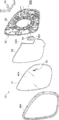
- FIG. 3 is an exploded perspective view of the mirror body 42 as viewed from the rear side of the vehicle and the outer side in the vehicle width direction (right side of the vehicle).
- a rectangular plate-like mirror 44 as a visual recognition part is provided at the vehicle rear side portion of the mirror body 42, and the surface of the mirror 44 (the vehicle rear side surface) is exposed to the vehicle rear side of the visor body 16. Yes.
- the mirror 44 is provided with a transparent glass plate, a reflective layer is provided on the back surface of the glass plate, and a mirror surface 44A is formed on the surface of the reflective layer on the glass plate side.
- the mirror surface 44A of the mirror 44 is directed to the rear side of the vehicle, and the mirror 44 assists the vehicle occupant (especially the driver) to see the rear side of the vehicle.
- a mirror holder 46 made of resin as a sliding body is provided on the vehicle front side portion of the mirror body 42.
- the mirror holder 46 is provided with a substantially rectangular plate-like base body 48, and an outer peripheral portion of the base body 48 on the vehicle rear side is provided with an edge 48 ⁇ / b> A over the entire periphery.
- the entire periphery of the edge portion 48 ⁇ / b> A covers the entire periphery of the mirror 44, the base body 48 covers the vehicle front side of the mirror 44, and the mirror holder 46 holds the mirror 44.
- a substantially cylindrical mounting wall 48B as a mounting portion (sliding part) is formed on the base body 48 on the vehicle front side of the center position (center of gravity position) of the mirror 44.
- the mounting wall 48B supports the visor body 16. It is arranged coaxially with the wall 20B.
- the mounting wall 48B has a substantially spherical wall shape, and the inner diameter of the mounting wall 48B is gradually increased toward the rear of the vehicle.
- a holding ball 22A of the holding cylinder 22 of the visor body 16 is fitted by elastic deformation of the mounting wall 48B, whereby the mounting wall 48B is tiltably and slidably held on the holding ball 22A ( Support).
- a substantially cylindrical sliding wall 48C as a sliding part is integrally provided on the vehicle front side of the base body 48, and the sliding wall 48C is disposed coaxially with the support wall 20B of the visor body 16.
- the sliding wall 48C has a spherical wall shape, and the outer diameter of the sliding wall 48C is gradually increased toward the rear of the vehicle.
- the outer peripheral surface of the sliding wall 48C is in contact with the inner peripheral surface of the support wall 20B, and the sliding wall 48C is tiltably and slidably supported by the inner peripheral surface of the support wall 20B.
- the base body 48 is integrally formed with a pair of substantially cylindrical rotating walls 48D as rotating portions on the radially inner side of the sliding wall 48C, and one rotating wall 48D supports the visor body 16.
- the other rotating wall 48D is disposed on the outer side in the vehicle width direction of the central axis of the support wall 20B (or on the inner side in the vehicle width direction). ing.
- the rotating wall 48D has a central axis line disposed in parallel with the central axis line of the support wall 20B of the visor body 16 and has a substantially spherical wall shape.
- the inner diameter dimension of the rotating wall 48D is from both ends in the vehicle front-rear direction. The size is gradually increased toward the center in the longitudinal direction of the vehicle.
- the tip end portion of the rod drive 40 in the mirror surface adjusting mechanism 34 is fitted and held.
- the rotating wall 48D is allowed to rotate with respect to the tip end portion of the rod drive 40, and the rod The rotation around the axis of the drive 40 is restricted. Therefore, as described above, when the wheel drive 38 (including the engagement claw 38B) is rotated in the mirror surface adjustment mechanism 34, the engagement position of the engagement claw 38B tip to the screw 40A of the rod drive 40 is displaced, The rod drive 40 is moved (slid) in the vehicle front-rear direction (axial direction). Thereby, the mirror body 42 (including the mirror 44 and the mirror holder 46) is tilted with respect to at least one of the vertical direction and the vehicle width direction.
- the mirror body 42 is provided with a blind spot monitor (BSM) as an electric device.
- BSM blind spot monitor
- a lighting portion 52 is provided at the end of the mirror 44 in the vehicle width direction outside and on the upper side.
- the lighting part 52 constitutes a predetermined pattern, and the part of the lighting part 52 of the mirror 44 is configured to transmit light without being provided with a reflective layer.
- the base 48 of the mirror holder 46 is provided with a recess 48E on the outer side in the vehicle width direction and on the upper portion, and the recess 48E is opened in a rectangular shape toward the vehicle rear side.
- An indicator 50 is accommodated in the recess 48E, and the vehicle rear side surface of the indicator 50 is attached to the mirror 44.
- An irradiation unit 50 ⁇ / b> A is provided on the vehicle rear side wall of the indicator 50, and the irradiation unit 50 ⁇ / b> A is opposed to the lighting unit 52 of the mirror 44.
- a light source (not shown) is provided inside the indicator 50, and the indicator 50 emits light from the irradiation unit 50 ⁇ / b> A to the lighting unit 52 by being electrically operated with power supplied from the control device. To do. As a result, the lighting unit 52 is turned on, and the BSM informs the occupant that another vehicle is present obliquely behind the vehicle.
- the mirror body 42 is provided with a heater 54 as an electric device.
- the heater 54 is formed in a sheet shape, and the heater 54 is attached to the back surface of the mirror 44.
- a cutout portion 54A is provided on the outer side and the upper side of the heater 54 in the vehicle width direction, and the heater 54 exposes the lighting portion 52 of the mirror 44 to the front side of the vehicle by the cutout portion 54A.
- the heater 54 generates heat when energized to heat the mirror 44. For this reason, defrosting of the surface of the mirror 44 is performed by the heater 54 generating heat.
- a connector 56 (bracket) as a receiving portion is integrally provided at the inner end of the reinforcement plate 26 of the reinforcement 24 in the vehicle width direction.
- the connector 56 is electrically connected to a control device on the power supply side via the rotating body 12B of the storage mechanism 12 and the stand 12A.
- the reinforcement 24 is integrally provided with a plurality of long strip-like conductive wires 58 constituting wiring by a plurality of insert moldings.
- the conducting wires 58 are extended from the reinforcing plate 26 to the bottom wall portion 28 via the stepped portion 30 in a state where the conducting wires 58 are almost entirely disposed in the reinforcement 24, and one end of each conducting wire 58 is electrically connected to the connector 56. And the other end of each conductive wire 58 is exposed on the vehicle rear side of the bottom wall portion 28.
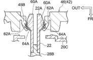
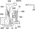
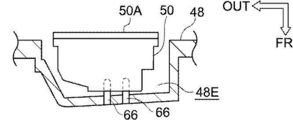
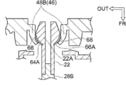
- FIG. 4A, FIG. 4B, and FIG. 4C are enlarged sectional views of the main part in FIG. 4A shows the holding cylinder 22 of the visor body 16 and the mounting wall 48B of the mirror holder 46, and FIG. 4B shows the support wall 20B of the visor body 16 and the sliding wall 48C of the mirror holder 46. . 4C shows a recess 48E of the base 48 of the mirror holder 46.
- the holding sphere 22A of the holding cylinder 22 is integrally provided with a pair of terminal plates 60A as terminal portions, and the terminal plate 60A is shaped like a plate, It is curved so as to be flush with the peripheral surface.
- the terminal plate 60A is electrically connected to the conductive wire 58 in the bottom wall portion 28 through the holding cylinder 22 by a first conductive wire (not shown).
- the electrical connection between the first conductive wire and the conductive wire 58 is as follows. This is done by contact conduction.
- a pair of terminal plates 60B as terminal portions are integrally provided on the outer side in the vehicle width direction of the support wall 20B, and the terminal plate 60B is formed in a plate shape to support the support wall. It is curved so as to be flush with the inner peripheral surface of 20B.
- the terminal plate 60B is electrically connected to the conductive wire 58 of the bottom wall portion 28 through the support wall 20B by a second conductive wire (not shown).
- the electrical connection between the second conductive wire and the conductive wire 58 is as follows. This is done by contact conduction.
- the mirror holder 46 is provided with terminals 62A and 62B as sliding portions, and the terminals 62A and 62B have a leaf spring shape (elastic body) using a metal plate material.
- the terminals 62A are provided in pairs on the mounting wall 48B.
- a recessed portion 64A is formed on the inner peripheral surface of the mounting wall 48B, and the terminal 62A is disposed in the recessed portion 64A so that the tip can protrude from the inner peripheral surface of the mounting wall 48B.
- the tip of the terminal 62A protrudes from the inner peripheral surface of the mounting wall 48B, thereby elastically pressing the terminal plate 60A of the holding ball 22A and being slidable with respect to the terminal plate 60A.
- the terminal 62A is electrically connected to the terminal plate 60A.
- the terminals 62B are provided in pairs on the sliding wall 48C.
- a concave portion 64B is formed on the inner peripheral surface of the sliding wall 48C, and the terminal 62B is disposed in the concave portion 64B so that the tip can protrude from the inner peripheral surface of the sliding wall 48C. Yes.
- the tip of the terminal 62B protrudes from the inner peripheral surface of the sliding wall 48C, thereby elastically pressing the terminal plate 60B of the support wall 20B and being slidable with respect to the terminal plate 60B.
- the terminal 62B is electrically connected to the terminal board 60B in the tilting range of the mirror body 42.
- the mirror holder 46 is integrally provided with conductive wires (not shown) as wiring by a plurality of insert moldings.
- a terminal 62A of the mounting wall 48B is integrally formed at one end of the pair of third conductors among the plurality of conductors, and the side opposite to the terminal 62A of the third conductor is extended in the base body 48.
- the heater 54 is electrically connected via a first terminal (not shown).
- second terminals 66 protrude in pairs from the bottom of the recess 48E of the base 48.
- the distal end portion of the second terminal 66 is inserted into and fitted into the bottom portion (bottom portion on the front side of the vehicle) of the indicator 50 (or is in contact with the electrode provided on the bottom portion).
- 50 is electrically connected to the light source in 50.
- a terminal 62B of the sliding wall 48C is integrally formed at one end of a pair of fourth conductors of the plurality of conductors, and is opposite to the terminals 62B of the fourth conductors.
- the side extends in the vehicle width direction outside in the base body 48 and is electrically connected to the second terminal 66.
- the indicator 50 and the terminal 62B are electrically connected via the fourth conductor, and the heater 54 and the terminal 62A are electrically connected via the third conductor.
- the motor 36 is driven by the electrical operation of the mirror surface adjustment mechanism 34 and the wheel drive 38 is rotated, whereby the rod drive 40 is moved in the vehicle longitudinal direction.
- the mirror body 42 including the mirror 44 and the mirror holder 46
- the mirror surface 44A angle of the mirror 44 is adjusted in at least one of the vertical direction and the width direction.
- the mounting wall 48B of the mirror body 42 is held (supported) while being slid by the holding balls 22A of the holding cylinder 22 of the visor body 16, and the mirror body 42 is slid.
- the wall 48C is supported while being slid on the support wall 20B of the visor body 16.
- the indicator 50 of the BSM when the indicator 50 of the BSM is electrically operated, light is irradiated from the irradiation unit 50A of the indicator 50 to the lighting unit 52 of the mirror 44, and the lighting unit 52 is turned on. In addition, the mirror 44 is heated by electrically operating the heater 54.
- a terminal plate 60A is provided on the holding ball 22A of the visor body 16, and a terminal 62A is provided on the mounting wall 48B of the mirror holder 46. Further, the terminal 62A is electrically connected to the heater 54 through the third conducting wire.
- the support wall 20B of the visor body 16 is provided with a terminal plate 60B, and the sliding wall 48C of the mirror holder 46 is provided with a terminal 62B. Further, the terminal 62B is electrically connected to the indicator 50 through the fourth conducting wire.
- the terminal plate 60A and the terminal 62A are slid and the electrical connection is maintained. Further, according to the tilt of the mirror body 42, the terminal plate 60B and the terminal 62B are slid and electrically connected.
- the movement of the harness due to the tilt of the mirror body 42 can be eliminated, and the disconnection due to the catch of the harness can be eliminated. Furthermore, since the harness is not seen between the mirror body 42 and the visor body 16, the appearance of the door mirror device 10 can be improved.
- the holding ball 22A and the support wall 20B of the visor body 16 on which the mounting wall 48B and the sliding wall 48C of the mirror holder 46 slide are used. Therefore, it is not necessary to separately provide the mirror holder 46 and the visor body 16 with a portion for electrically connecting the mirror holder 46 side to the visor body 16 side. Thereby, complicating the shapes of the visor body 16 and the mirror holder 46 can be suppressed.
- the harness 62 is electrically connected between the terminals 62A and 62B and the indicator 50 and the heater 54 in the mirror holder 46.
- the harness 62 is electrically connected between the terminals 62A and 62B and the indicator 50 and the heater 54 in the mirror holder 46.
- the terminal plate 60A is provided on the holding ball 22A and the terminal 62A is provided on the mounting wall 48B.
- the terminal plate 60A is provided on the support wall 20B in the same manner as the terminal plate 60B.
- the terminal 62A may be provided on the sliding wall 48C in the same manner as the terminal 62B.
- the terminal plate 60A may be in elastic contact with the terminal 62A, and the terminal plate 60B may be in elastic contact with the terminal 62B.
- the mirror holder 46 may be provided with a terminal plate 68 in place of the terminal 62A as the sliding portion (the same applies to the terminal 62B).
- the terminal board 68 has a plate shape, is curved so as to be flush with the inner peripheral surface of the mounting wall 48B, and is provided integrally with the third electric wire.
- the terminal plate 68 is elastically deformed together with the mounting wall 48B, and the holding ball 22A is fitted to the mounting wall 48B. Accordingly, the terminal plate 60A and the terminal plate 68 are slidable and electrically connected, and the terminal plate 68 is supported by the terminal plate 60A.
- the terminal plate 68 is supported by the terminal plate 60A, a sliding portion is provided between the visor body 16 and the mirror body 42 in addition to the portion where the mirror body 42 is supported to be tiltable. It is possible to eliminate the need to provide a sliding part.
- the terminal board 68 slid by the terminal board 60A was taken as an example, the terminal board 68 may be provided on the sliding wall 48C so as to be slidable with the terminal board 60B of the support wall 20B. good. Accordingly, the mirror body 42 can be supported by the terminal plate 60B and the terminal plate 68 between the sliding wall 48C and the support wall 20B.
- the holding ball 22A provided with the terminal portions (terminal plates 60A, 60B) and the support wall 20B are integrally formed with the visor body 16, but the terminal portions are separated from the visor body 16. You may provide in the case where the mirror surface adjustment mechanism 34 is accommodated. In other words, at least one of the holding ball 22A (holding cylinder 22) and the support wall 20B provided with the terminal portion may be formed in a case separate from the visor body 16.
- the mirror body 42 using the mirror 44 as the visual recognition part has been described as an example.
- the visual recognition part is replaced by the mirror 44 and an electrochromic anti-glare mirror (EC mirror) as an electric device is used. It may be used.
- the EC mirror is actuated by the light transmitted through the electrochromic layer being reflected and being supplied with a driving voltage, thereby reducing the light transmittance of the electrochromic layer (anti-glare).
- the sliding wall 48C is provided with a sliding portion similar to the terminal 62B or the terminal plate 68
- the supporting wall 20B is provided with a sliding portion similar to the terminal plate 60B
- the sliding portion is formed by a conducting wire. Electrically connected to the EC mirror. Accordingly, since the EC mirror and the terminal portion are electrically connected, it is possible to operate the EC mirror without having to route a harness.
- the door mirror device 10 using the mirror body 42 as the visual recognition unit has been described as an example.
- an imaging unit such as a camera is used as the visual recognition unit, and the imaging unit is slid onto the case as the container.
- the present invention may be applied to a vehicular visual recognition device that is supported so as to be movable and tiltable.
Landscapes
- Engineering & Computer Science (AREA)
- Multimedia (AREA)
- Mechanical Engineering (AREA)
- Rear-View Mirror Devices That Are Mounted On The Exterior Of The Vehicle (AREA)
- Lighting Device Outwards From Vehicle And Optical Signal (AREA)
Abstract
L'invention concerne un dispositif de rétroviseur de porte (10) qui est équipé des éléments suivants : une plaque à bornes (60A) qui est disposée sur une bille de retenue (22A) d'un corps de pare-soleil (16) et auquel une borne (62A) d'une paroi de montage (48B) d'un support de miroir (46) est électriquement connectée en coulissement ; et une plaque à bornes (60B) qui est disposée sur une paroi de support (20B) du corps de pare-soleil (16) et à laquelle une borne (62B) d'une paroi coulissante (48C) du support de miroir (46) est électriquement connectée en coulissement. Ainsi, un corps de miroir incliné (42) et le corps de pare-soleil (16) sont électriquement connectés, ce qui permet d'éliminer la nécessité de câbler un harnais entre le corps de pare-soleil (16) et le corps de miroir (42).
Applications Claiming Priority (2)
| Application Number | Priority Date | Filing Date | Title |
|---|---|---|---|
| JP2016026141A JP6629092B2 (ja) | 2016-02-15 | 2016-02-15 | 車両用視認装置 |
| JP2016-026141 | 2016-02-15 |
Publications (1)
| Publication Number | Publication Date |
|---|---|
| WO2017141633A1 true WO2017141633A1 (fr) | 2017-08-24 |
Family
ID=59625774
Family Applications (1)
| Application Number | Title | Priority Date | Filing Date |
|---|---|---|---|
| PCT/JP2017/002166 Ceased WO2017141633A1 (fr) | 2016-02-15 | 2017-01-23 | Dispositif de visualisation pour véhicules |
Country Status (2)
| Country | Link |
|---|---|
| JP (1) | JP6629092B2 (fr) |
| WO (1) | WO2017141633A1 (fr) |
Families Citing this family (1)
| Publication number | Priority date | Publication date | Assignee | Title |
|---|---|---|---|---|
| JP2019077312A (ja) * | 2017-10-24 | 2019-05-23 | 株式会社東海理化電機製作所 | 車両用ミラー装置 |
Citations (4)
| Publication number | Priority date | Publication date | Assignee | Title |
|---|---|---|---|---|
| JP2005027054A (ja) * | 2003-07-02 | 2005-01-27 | Fujitsu Ten Ltd | スピーカシステム |
| JP2010030468A (ja) * | 2008-07-29 | 2010-02-12 | Murakami Corp | 車両装備品 |
| JP2013010383A (ja) * | 2011-06-28 | 2013-01-17 | Ishizaki Honten Co Ltd | 車両用ミラーホルダー |
| JP2013166439A (ja) * | 2012-02-15 | 2013-08-29 | Suzuki Motor Corp | インホイールモータへの電力供給構造 |
Family Cites Families (1)
| Publication number | Priority date | Publication date | Assignee | Title |
|---|---|---|---|---|
| JPH05283U (ja) * | 1991-06-17 | 1993-01-08 | マツダ株式会社 | スポツト溶接機の給電装置 |
-
2016
- 2016-02-15 JP JP2016026141A patent/JP6629092B2/ja not_active Expired - Fee Related
-
2017
- 2017-01-23 WO PCT/JP2017/002166 patent/WO2017141633A1/fr not_active Ceased
Patent Citations (4)
| Publication number | Priority date | Publication date | Assignee | Title |
|---|---|---|---|---|
| JP2005027054A (ja) * | 2003-07-02 | 2005-01-27 | Fujitsu Ten Ltd | スピーカシステム |
| JP2010030468A (ja) * | 2008-07-29 | 2010-02-12 | Murakami Corp | 車両装備品 |
| JP2013010383A (ja) * | 2011-06-28 | 2013-01-17 | Ishizaki Honten Co Ltd | 車両用ミラーホルダー |
| JP2013166439A (ja) * | 2012-02-15 | 2013-08-29 | Suzuki Motor Corp | インホイールモータへの電力供給構造 |
Also Published As
| Publication number | Publication date |
|---|---|
| JP6629092B2 (ja) | 2020-01-15 |
| JP2017144782A (ja) | 2017-08-24 |
Similar Documents
| Publication | Publication Date | Title |
|---|---|---|
| JP4711983B2 (ja) | 車輌用灯具 | |
| CN1318239C (zh) | 车辆用外反射镜 | |
| US7914186B2 (en) | Lighting device for vehicle | |
| KR100198321B1 (ko) | 차량용 후시경의 위치결정장치 | |
| US20080112181A1 (en) | Lighting device for vehicle and optical axis regulating device of lighting device for vehicle | |
| CN101348092B (zh) | 车辆用灯具的光轴调整装置 | |
| JPH01282045A (ja) | 車輌用前照灯の傾動装置 | |
| CN101725883A (zh) | 车辆用前照灯 | |
| CN100582563C (zh) | 车辆用灯具 | |
| WO2018143202A1 (fr) | Dispositif de reconnaissance visuelle de véhicule | |
| WO2017141633A1 (fr) | Dispositif de visualisation pour véhicules | |
| US20190077317A1 (en) | Vehicle visual recognition device | |
| CN108883727A (zh) | 车门镜装置 | |
| WO2018051764A1 (fr) | Dispositif de visualisation de véhicule | |
| WO2018056014A1 (fr) | Appareil de visualisation pour véhicule | |
| JP5494387B2 (ja) | 車両用ミラー装置 | |
| JP2006248368A (ja) | 車両用アウトサイドミラー装置 | |
| WO2018056015A1 (fr) | Appareil d'observation visuelle pour véhicule | |
| JP6460384B2 (ja) | ヘッドアップディスプレイ装置 | |
| JPH0788150B2 (ja) | 車輌用前照灯装置 | |
| WO2017010331A1 (fr) | Dispositif de confirmation visuelle de véhicule | |
| JP2009286167A (ja) | 室内照明装置 | |
| JP2017019462A (ja) | 車両用視認装置 | |
| KR920001712B1 (ko) | 차량용 전조등 장치 | |
| CN111717117A (zh) | 车辆的可显示内部后视镜 |
Legal Events
| Date | Code | Title | Description |
|---|---|---|---|
| 121 | Ep: the epo has been informed by wipo that ep was designated in this application |
Ref document number: 17752897 Country of ref document: EP Kind code of ref document: A1 |
|
| NENP | Non-entry into the national phase |
Ref country code: DE |
|
| 122 | Ep: pct application non-entry in european phase |
Ref document number: 17752897 Country of ref document: EP Kind code of ref document: A1 |