WO2017141783A1 - Dispositif de poignée pour plaque de véhicule - Google Patents
Dispositif de poignée pour plaque de véhicule Download PDFInfo
- Publication number
- WO2017141783A1 WO2017141783A1 PCT/JP2017/004522 JP2017004522W WO2017141783A1 WO 2017141783 A1 WO2017141783 A1 WO 2017141783A1 JP 2017004522 W JP2017004522 W JP 2017004522W WO 2017141783 A1 WO2017141783 A1 WO 2017141783A1
- Authority
- WO
- WIPO (PCT)
- Prior art keywords
- board
- base
- retaining member
- handle
- pair
- Prior art date
- Legal status (The legal status is an assumption and is not a legal conclusion. Google has not performed a legal analysis and makes no representation as to the accuracy of the status listed.)
- Ceased
Links
Images




Classifications
-
- B—PERFORMING OPERATIONS; TRANSPORTING
- B60—VEHICLES IN GENERAL
- B60R—VEHICLES, VEHICLE FITTINGS, OR VEHICLE PARTS, NOT OTHERWISE PROVIDED FOR
- B60R5/00—Compartments within vehicle body primarily intended or sufficiently spacious for trunks, suit-cases, or the like
- B60R5/04—Compartments within vehicle body primarily intended or sufficiently spacious for trunks, suit-cases, or the like arranged at rear of vehicle
Definitions
- the present invention relates to a vehicle board handle device for gripping a vehicle board such as a deck board installed in the vehicle.
- a storage section for storing spare tires, utility boxes and the like is provided below the cargo floor located behind the rear seat of the automobile.
- the accommodating portion is always covered with a deck board, and the accommodating portion can be used by holding the handle device attached to the deck board and lifting the deck board as necessary.
- Japanese Patent Application Laid-Open No. 2004-228561 discloses a vehicle board handle device having an upper body and a lower body that sandwich and fix a board mounting hole, and a handle rotatably supported by the upper body.
- the upper body has a thin box shape with an upper opening, and a pair of screw receiving bosses are suspended from the bottom surface, while the lower body has a thin box shape with an upper opening that can accommodate the upper body.
- a pair of screw insertion holes is formed in the.
- the lower body is packaged on the upper body protruding from the back side of the mounting hole, and the flange is placed on the back side of the mounting hole.
- the upper body and the lower body are assembled and fixed in the mounting hole by bringing them into contact and tightening and fixing the screws to the screw receiving bosses of the upper body through the screw insertion holes of the lower body.
- the handle is gripped and lifted, the deck board is pulled up via the lower body fixed to the upper body.
- an object of the present invention is to provide a handle device for a vehicle board, in which the retaining member can be securely secured to the base and the workability of assembling the base and the retaining member is good. It is in.
- the present invention provides a vehicle board handle device having a handle for operating a board that can be opened and closed inside a vehicle, wherein the board has a mounting hole provided in the board.
- a base attached from the front side of the board; and a retaining member attached to the base in a state where the hole edge of the attachment hole is sandwiched from the back side of the board, and the base is inserted into the attachment hole
- a first flange portion that extends from the outer periphery of the main body portion and abuts against a front side periphery of the mounting hole, and the main body portion protrudes on the back side of the mounting hole;
- a first engagement portion provided on the first side wall portion and disposed to face the first flange portion, wherein the retaining member is adjacent to the outside of the first side wall portion.
- a second side wall disposed A second flange portion extending outwardly from the second side wall portion and abutting against a rear peripheral edge of the mounting hole; and a second engagement portion provided on the second side wall portion, and the second engagement The part is engaged with the first engaging part by being slid between the first engaging part and the back surface of the board.
- the handle is supported by the first side wall portion of the base, and the first engagement portion of the base is arranged in the direction perpendicular to the board in the first direction. It is preferable that the first side wall portion is provided so as to face a portion of the side wall portion that supports the handle.
- the first engagement portion and / or the second engagement portion have an engagement surface extending along a back surface of the board. .
- the retaining member may be a cover that covers the opening formed in the main body of the base so as to open to the back side of the mounting hole. preferable.
- the handle is supported by the first side wall portion on one end side of the main body portion, and the other end side of the main body portion is connected to the first flange portion. It is preferable that an engaging claw that engages with the back side periphery of the mounting hole is formed integrally with the board interposed therebetween.
- the retaining member is provided with a bottom wall that covers the opening, and the main body of the base includes the bottom wall of the retaining member.
- a partition wall facing the base in the sliding direction is provided with a partition wall facing in the sliding direction, and a fitting part is provided between the partition wall and the bottom wall for connecting the two. preferable.
- the main body portion and the retaining member are engaged between the base end portion of the retaining member in the sliding direction with respect to the base and the main body portion. It is preferable that the latching
- the main body portion of the base is inserted into the mounting hole, the first flange portion of the base is brought into contact with the front peripheral edge of the mounting hole, the retaining member is slid along the back surface of the board, and the first By engaging the second engaging portion with the engaging portion, the retaining member is held in the body portion in a state where the edge of the mounting hole is sandwiched between the first flange portion of the base and the second flange portion of the retaining member. Can be assembled with good workability.
- a load is applied in a direction intersecting the slide introduction direction of the second engagement portion between the first engagement portion and the back surface of the board.
- the retaining member can be firmly retained and fixed.
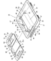
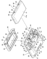
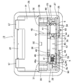
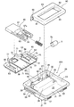
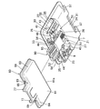
- FIG. 2 is an enlarged exploded perspective view of a main part of the handle device viewed from a direction different from that in FIG. 1. It is a principal part enlarged plan view of the handle apparatus.
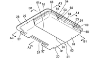
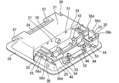
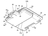
- FIG. 3 is a perspective view of the handle device in a state where a retaining member is assembled to a base.
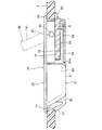
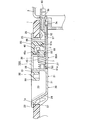
- FIG. 6 is a cross-sectional view of the handle device taken along the line A1-A1 in FIG.
- FIG. 6 is a cross-sectional view of the handle device taken along the line A3-A3 in FIG.
- FIG. 6 is a cross-sectional view of the handle device taken along the line A3-A3 in FIG.
- FIG. 6 is a cross-sectional view of the handle device taken along the line B1-B1 in FIG.
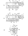
- the other shape of the slide engagement structure of the handle device is shown, (a) is a main part explanatory diagram of the first shape, (b) is a main part explanatory diagram of the second other shape, (c) is the third other It is principal part explanatory drawing of a shape.
- steering-wheel apparatus is shown, and it is the perspective view of the 4th shape. It is a disassembled perspective view which shows other embodiment of the handle
- FIG. 12 is an enlarged exploded perspective view of a main part of the handle device viewed from a direction different from FIG. 11.
- FIG. 12 is an enlarged exploded perspective view of a main part of the handle device viewed from a direction different from FIG. 11.
- FIG. 3 is a perspective view of the handle device in a state where a retaining member is assembled to a base.
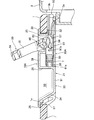
- FIG. 14 is a cross-sectional view of the handle device taken along the line A2-A2 in FIG. 13. It is sectional drawing of the state which rotated the handle from the state shown in FIG.
- FIG. 14 is a cross-sectional view of the handle device taken along the line B2-B2 in FIG.
- a vehicle board handle device 10 (hereinafter referred to as “handle device 10”) of this embodiment has a handle 80 for operating a board 1 that is attached to the inside of the vehicle so as to be opened and closed.
- a base 20 attached from the front side of the board 1 to a mounting hole 1a (here, a substantially square hole shape) opened in the board 1 and a hole edge of the mounting hole 1a sandwiched from the back side of the board 1 And a retaining member 60 to be assembled to the base 20.
- the handle device 10 of this embodiment includes a handle 80 that is rotatably attached to the base 20, a torsion spring 5 that urges the handle 80 in a direction close to the base 20, and a rotating operation of the handle 80. And a damper 9 for imparting a damping force to.
- the torsion spring 5 has a cylindrical coil part 5a formed by winding a spring wire, one end part 5b extending from one end of the coil part 5a, and the other end part 5c extending from the other end of the coil part 5a. ing.
- the board in this embodiment is a so-called deck board that opens and closes the opening of the storage part 3 of the cargo compartment of the vehicle.
- the board is installed in the vehicle.
- the board is not particularly limited.
- a step portion 3a is provided at the periphery of the opening of the housing portion 3, and the board 1 is placed on the step portion 3a.
- the base 20 includes a main body portion 21 inserted into the mounting hole 1 a of the board 1, and a first flange that extends from the outer periphery of the main body portion 21 and contacts the front peripheral edge of the mounting hole 1 a.
- the main body 21 includes a recess 33 that accommodates the grip portion 84 of the handle 80, a pair of first side wall portions 22 and 23 that protrude from the back side of the mounting hole 1a, and the pair of first side wall portions 22 and 23.
- the first engaging portions 58 and 58 are provided so as to face the first flange portion 28.
- the main body portion 21 includes the pair of first side wall portions 22 and 23 arranged in parallel to each other, and is orthogonal to the first side wall portions 22 and 23.
- a front wall 24 that is disposed and connects one end portions of the first side wall portions 22 and 23 in the longitudinal direction to each other, and is disposed orthogonally to the first side wall portions 22 and 23, and the like in the longitudinal direction of the first side wall portions 22 and 23. It has a substantially square frame shape composed of a rear wall 25 connecting the end portions to each other.
- the first flange portion 28 extends from the outer periphery of the opening of the main body portion 21 so as to form a square ring (see FIG. 2).
- a partition wall 26 arranged orthogonal to the first side wall portions 22, 23 is connected to a predetermined position in the longitudinal direction of the pair of first side wall portions 22, 23.
- the internal space of the base 20 is partitioned.
- the partition wall 26 is erected at a height reaching the flange portion 28 of the base 20 except for both sides in the longitudinal direction.
- the partition wall 26 is provided on a bottom wall 61 of the retaining member 60, which will be described later, so as to face a distal end portion 61 a in the sliding direction with respect to the base 20 in the sliding direction.
- a “fitting portion” is provided between the front end portion 61 a of 61 and connects the two (the fitting portion will be described later).
- the body portion 21 is provided with the rotation support portions 30 and 30 of the handle 80 on one end side through the partition wall 26, and the recess 33 for accommodating the grip portion 84 of the handle 80 on the other end side.
- the main body 21 has a structure in which an opening 27 is provided at the bottom on one end side.
- the rotation support portions 30 and 30 having a round hole shape are formed on one end side (position near the rear wall 25) of the main body portion 21 of the pair of first side wall portions 22 and 23.
- a pair of protrusion-shaped rotation receiving portions 85, 85 (to be described later) provided on the handle 80 are fitted to the rotation support portions 30, 30 (see FIG. 8), and the handle 80 is attached to the base 20.
- the rotation support part on the base side may have a concave shape or a protrusion shape instead of a hole shape (in this case, the rotation receiving portion on the handle side has a hole shape or a concave shape). ), As long as the handle can be rotated.
- the other end side of the main body 21, that is, a portion surrounded by the front wall 24, the partition wall 26, and the pair of first side wall portions 22 and 23, and an upper opening portion where the handle 80 appears and disappears The opposite end is closed by the bottom wall 31, thereby forming the recess 33 in the main body 21 that can accommodate the gripping portion 84 of the handle 80.
- the opening 27 is formed so as to open to the mounting hole 1a of the board 1 on the back side.
- the opening part 27 formed in the one end side of the main-body part 21 is covered with the retaining member 60 (refer FIG. 6).
- a pair of inner side walls 37, 38 extend from both sides of the partition wall 26 in parallel to the pair of first side wall parts 22, 23.
- the pair of inner side walls 37 and 38 are erected at a height reaching the second flange portion 28 of the base 20.
- a long plate-shaped ceiling wall 39 is connected between the pair of inner side walls 37, 38 in the standing direction tip and the standing direction tip of the partition wall 26, and is raised in the form of an elongated block from the bottom of the base.
- the part is configured (see FIG. 2).
- FIG. 2 at the position adjacent to the rear wall 25 of the opening 27, there is a slot-like opening 35 that extends in a slot shape along the rear wall 25 in communication with the base opening.
- a rotation portion 83 (see FIG. 1), which will be described later, of the handle 80 is arranged in the slot-shaped opening 35.
- a pair of wall parts 41 and 41 are provided toward the direction which mutually approaches from the edge part by the side of the rear wall 25 of a pair of inner side walls 37 and 38, A pair of slide holding claws 43, 43 are erected between the pair of wall portions 41, 41 at a predetermined interval. Further, a pair of slide holding claws 44, 44 are erected on the rear wall 25 at positions facing the pair of slide holding claws 43, 43, and the lock piece 90 is formed by these four slide holding claws. (Refer to FIG. 11 and FIG. 12) can be slidably held.
- the base 20 has a lock piece accommodating portion for accommodating a lock piece 90 (see FIGS. 11 and 12) for holding the board 1 in a closed state.
- a lock piece 90 see FIGS. 11 and 12
- FIG. 4 when the base 20 is viewed from the plane direction, it is surrounded by the pair of slide holding claws 44, 44, the pair of slide holding claws 43, 43, and the partition wall 26.
- the space provided along the slide locus of the lock piece 90 forms the lock piece housing portion 45.
- a spring having an axial shape is formed in a slot-like opening 35 formed in the base 20 and at a position near one first side wall 22 via a support piece 46a.
- the mounting portion 46 is provided so as to project toward the other first side wall portion 23.
- the coil portion 5 a of the torsion spring 5 is externally mounted on the outer periphery of the spring mounting portion 46, and one end portion 5 b is engaged with the back surface side of the base 20, and the other end portion 5 c is engaged with the back surface side of the handle 80. It is supposed to be.
- a damper rotation restricting portion 48 that prevents the damper 9 from rotating is provided at a position inward of the slot-like opening 35 of the base 20 and near the other side wall 23.
- the damper 9 is a so-called rotary damper, and a protrusion 9a (see FIG. 1) protruding from one side in the circumferential direction engages with the handle 80, and a pair of protrusions 9c, 9c on the damper base end side Abutting against the damper rotation restricting portion 48 to prevent rotation (see FIGS. 3 and 8), and further, attached to a damper attaching portion 87 of the handle 80 described later via the shaft 9b (FIG. 8).
- the damper structure is not particularly limited, and the damper may not be attached.
- a projecting shape is formed along the sliding direction of the lock piece 90 from the longitudinal center of the partition wall 26, and the coil spring 7 (see FIG. 14) in the embodiment described later is formed.
- a spring mounting portion 50 that supports one end portion is projected.
- the pair of locking holes 51, 51 constitute the “fitting portion” in the present invention.
- a thin plate-like guide piece 52 is provided on the outer surface side of the rear wall 25 (on the side opposite to the inside of the base) and between the pair of slide holding claws 44, 44. Is protruding.
- the guide piece 52 enters a recess 67 of a retaining member 60 described later (see FIG. 6), while the guide piece 52 has a lock piece as in an embodiment described later. In this case, it is arranged on the upper surface of the lock piece 90 (see FIGS. 14 and 15) and forms a slide guide for the lock piece 90.
- a pair of locking projections 53, 53 project from the outer surface side of the rear wall 25 and on both sides of the guide piece 52. As shown in FIG. 5, the pair of locking projections 53 and 53 are locked in a pair of locking holes 68 and 68 of a retaining member 60 described later, and are pulled out by a pulling force when the handle is operated. The base 20 is prevented from floating from the stop member 60.
- the pair of locking projections 53 and 53 constitutes a “locking portion” in the present invention.
- the first flange is located outside the pair of locking projections 53, 53 and slightly more than the same pair of locking projections 53, 53.
- a pair of retaining claws 54, 54 provided with a downward projecting portion on the distal end side is extended at a position near the portion 28.
- the pair of retaining claws 54, 54 are engaged with a pair of notches 69, 69 of a retaining member 60 described later, so that the retaining member 60 is detached from the base 20.
- the pair of retaining claws 54, 54 constitutes the “locking portion” in the present invention.
- a pair of engaging claws that engage with the rear peripheral edge of the mounting hole 1 a of the board 1 on the other end side of the main body 21, here the outer surface side of the front wall 24. 57, 57 are integrally formed (see FIG. 6).
- first engaging portions 58, 58 disposed so as to face the first flange portion 28.
- first engaging portions 58, 58 slide along the back surface of the board 1 with other mating engaging portions, here second engaging portions 74, 74 described later of the retaining member 60. It is arranged so that it can be introduced.
- the partition walls are provided on the outer surface side of the pair of first side wall portions 22 and 23 from the front end surface on the rear wall 25 side toward the partition wall 26.
- the first engaging portions 58 and 58 having a guide groove shape are formed in a length extending to 26.
- each first engagement portion 58 has an engagement surface 59 extending along the back surface of the board 1.
- the surface of the first engaging portion 58 having a guide groove shape facing the first flange portion 28 is continuously flat along the back surface of the board 1.
- An engaging surface 59 extending in a shape is formed.
- each first engagement portion 58 is a portion that supports the handle 80 of the first side wall portions 22, 23 in the direction perpendicular to the board 1 (here, the handle 80. Are provided on the pair of first side wall portions 22 and 23 so as to be opposed to the rotation support portion 30) that supports the rotation.
- the second engagement portions 74 and 74 of the retaining member 60 are slidably engaged with the first engaging portions 58 and 58 so that the retaining member 60 can be slid and assembled.
- the retaining member 60 is assembled and fixed to the base 20 (see FIGS. 7 and 8). In this state, as shown in FIGS. 7 and 8, the engagement surface 59 of the first engagement portion 58 is engaged with the engagement surface 75 of the second engagement portion 74 on the retaining member 60 side.
- the base 20 and the retaining member 60 are fixed to each other.
- the first engaging portion is “disposed so as to face the first flange portion” means that the first engaging portion directly faces the first flange portion. Even if the first engagement portion is not directly opposed to the first flange portion as shown by the imaginary line in the partial enlarged view of FIG.
- the portion that engages with the second engagement portion here, the engagement surface 59 only needs to face the first flange portion.
- the first engagement portion may not be a guide groove shape, but may be another shape (described later together with the second engagement portion), and is not particularly limited.
- the retaining member 60 of this embodiment is configured such that the base 20 attached to the attachment hole 1 a of the board 1 is retained so as not to be detached from the attachment hole 1 a. 20 and a cover that covers the opening 27 formed in the main body 21 of the base 20 so as to open to the back side of the mounting hole 1a.
- the retaining member 60 includes an opening 27 of the main body 21, that is, an opening surrounded by the rear wall 25 of the base 20, the partition wall 26, and the pair of first side wall portions 22 and 23. 27, a bottom wall 61 having an elongated plate shape extending long in one direction, and a pair of first bases of the base 20 erected in parallel from both peripheral edges of the bottom wall 61 in the longitudinal direction.
- the second side wall parts 63 and 63 arranged adjacent to the outside of the side wall parts 22 and 23, the one end part in the longitudinal direction of the pair of second side wall parts 63 and 63, and the one side part in the width direction of the bottom wall 61 are mutually connected.
- a connecting wall 64 to be connected, and has a lid shape with the upper side and the side opened. Further, from the outer periphery of the upper opening portion of the retaining member 60, a second flange portion 66 having a substantially U-shape is widened, and the second flange portion 66 is a peripheral edge on the back side of the mounting hole 1 a provided in the board 1. (See FIG. 8).
- the pair of second side wall portions 63, 63 are provided with second engagement portions 74, 74 that engage with the pair of first engagement portions 58, 58 of the base 20. ing.
- each second engagement portion 74 has an engagement surface 75 extending along the back surface of the board 1.
- the surface of the second engagement portion 74 that is disposed opposite to the engagement surface 59 of the first engagement portion 58 is an engagement surface that continuously extends in a planar shape along the back surface of the board 1. 75 (see FIGS. 7 and 8).
- the second engaging portion 74 is slid between the first engaging portion 58 provided on the main body portion 21 of the base 20 and the back surface of the board 1.
- the first engaging portion 58 is engaged.
- the second engaging portions 74 and 74 are engaged with the engaging surfaces of the first engaging portions 58 and 58 having a guide groove shape of the base 20 when the retaining member 60 is assembled to the base 20.
- 59 and 59 are slid to slide the retaining member 60 and engage with the first engaging portions 58 and 58 so that the retaining member 60 is assembled and fixed to the base 20. ing.
- the engagement surface 75 of the second engagement portion 74 is engaged with the engagement surface 59 of the first engagement portion 58 on the base 20 side.
- the base 20 and the retaining member 60 are fixed to each other.
- the first engagement portion 58 on the base 20 side has a guide groove shape
- the second engagement portion 74 on the retaining member 60 side also has a guide rail shape
- the guide rail is on the guide groove.
- the first engaging portion and the second engaging portion are both arranged along the back surface of the board 1 so that the mating engaging portion can be slid.
- first engagement portion and the second engagement portion may be arranged so that the mating engagement portion can be slid along the back surface of the board.
- shape of the first engagement portion and the second engagement portion may be a plurality of protrusions provided intermittently along the back surface of the board, instead of the guide rail and the guide groove extending continuously,
- first engagement portion may have a guide groove shape
- the second engagement portion may have a guide rail shape, which is not particularly limited. 9 and 10 show such a structure.
- the first engagement portion 58a on the base 20 side has a mountain shape with a sharp top, and a plurality of the first engagement portions 58a are provided intermittently along the back surface of the board.
- the second engaging portion 74 on the side has a guide rail shape. Even in this case, the second engagement portion 74 is configured to engage with the first engagement portion 58a by being slid between the first engagement portion 58a and the back surface of the board.
- the second engagement portion 74b of the retaining member 60 has a rounded protrusion shape protruding toward the first engagement portion 58b side of the base 20, and this is along the back surface of the board.
- the first engaging portion 58b on the base 20 side has a guide groove shape.
- the second engaging portion 74b is configured to engage the first engaging portion 58b by being slid between the first engaging portion 58b and the back surface of the board.
- the first engagement portion 58c on the base 20 side has a protruding guide rail shape
- the second engagement portion 74c on the retaining member 60 side has a guide groove shape.
- the first engaging portion 58c and the second engaging portion 74c can slide the mating engaging portion along the back surface of the board.
- the second engaging portion 74c is configured to engage with the first engaging portion 58c by being slid between the first engaging portion 58c and the back surface of the board.
- the first engagement portion 58d on the base 20 side has a rectangular protrusion shape, and a plurality of the first engagement portions 58d are provided intermittently along the back surface of the board.
- the second engaging portion 74 on the retaining member 60 side has a guide rail shape. Even in this case, the second engaging portion 74 is configured to engage with the first engaging portion 58d by being slid between the first engaging portion 58d and the back surface of the board.
- a spring mounting portion 46 projects from the base 20 also from the second side wall portion 23 side.
- the bottom wall 61 constituting the retaining member 60 covers the opening 27 of the main body 21, and the front end 61 a in the sliding direction with respect to the base 20 is arranged to face the partition wall 26 of the base 20. It has become.
- the retaining member 60 is pushed into the base 20 through the first engaging portion 58 and the second engaging portion 74 and is slid and assembled so that the retaining member 60 is pushed in as much as possible.
- the front end 61a of the bottom wall 61 abuts against the partition wall 26 of the base 20 and is fitted so as to close the opening 27 of the main body 21 of the base 20, and in this state, the main body 21 of the base 20
- the bottom wall 31 is configured to be in a flush state with no step (see FIGS. 5 to 7).
- a concave portion 67 into which the guide piece 52 of the base 20 enters is formed in the longitudinal center portion of the second flange portion 66 on the connecting wall 64 side.
- a pair of retaining members 60 are located at the base end portions in the sliding direction with respect to the base 20, here, at positions corresponding to both sides of the concave portion 67 of the connecting wall 64.
- Lock holes 68 and 68 are formed, and a pair of notches 69 and 69 are formed at positions corresponding to the outside of the pair of lock holes 68 and 68 of the second flange portion 66 on the connecting wall 64 side.
- the pair of locking holes 68, 68, the pair of notches 69, 69, the pair of locking projections 53, 53 on the base 20 side, and the pair of retaining claws 54, 54 are provided in the present invention.
- a locking hole may be provided on the base side, and a locking protrusion that locks the locking hole on the retaining member side may be provided, and is not particularly limited.
- a pair of protrusions 70, 70 disposed outside the slide holding claws 43, 43 and the pair of slide holding claws 44, 44 extend perpendicular to the longitudinal direction of the bottom wall 61.
- the pair of protrusions 70, 70 regulates the outward bending of the pair of slide holding claws 43, 43 and the pair of slide holding claws 44, 44 when the retaining member 60 is assembled to the base 20.
- Locking claws 71 and 71 are provided at the front ends in the direction to be locked in a pair of locking holes 51 and 51 provided in the partition wall 26 of the base 20. That is, the pair of locking claws 71 and 71 and the pair of locking holes 51 and 51 on the base 20 side form a “fitting portion” in the present invention.
- any structure can be used as long as it is provided between the tip end part of the bottom wall of the retaining member in the sliding direction with respect to the base and the partition wall of the main body part and connects both of them.
- a structure may be used.
- a locking hole may be provided in the base-side partition wall, and a locking projection for locking in the locking hole may be provided on the bottom wall side of the retaining member, and there is no particular limitation.
- Relief portions 72, 72 having an elongated concave shape are formed (see FIGS. 2 and 8).
- regulation walls 73 and 73 having ridges are provided on the inner surface side of the bottom wall 61 and on one side edge of the ridges 70 and 70 side of the pair of escape portions 72 and 72.
- One regulating wall 73 is disposed opposite to the first spring mounting portion 46 provided on the base 20 and adjacent to the inside of one side portion 81 of the handle 80, and the other regulating wall 73 is disposed on the base 20. Is disposed adjacent to the inner side of the other side portion 82 of the handle 80 (see FIG. 8).
- the handle 80 includes a pair of side portions 81 and 82 arranged in parallel to each other, and is disposed orthogonally to the pair of side portions 81 and 82, and A rotating portion 83 that connects one end in the longitudinal direction to each other and a pair of side portions 81 and 82 that are orthogonally connected to each other and connect the other ends in the longitudinal direction of both side portions 81 and 82 to each other. It has a substantially quadrangular ring shape that includes a gripping portion 84 that forms a circle.
- the pair of side portions 81 and 82 are arranged inside the pair of first side wall portions 22 and 23 of the base 20, and further, the rotating portion 83 of the pair of side portions 81 and 82.
- projecting rotation receiving portions 85, 85 are projected, and these rotation receiving portions 85, 85 are inserted into the pair of rotation support portions 30, 30 of the base 20.
- the handle 80 is rotatably attached to the first side wall portions 22 and 23 on one end side of the main body portion 21 of the base 20 (see FIG. 8).
- the rotation receiving portions 85 and 85 protrude in a columnar shape, and a tapered surface is formed at a tip portion thereof.
- the rotation receiving portions 85 and 85 are fitted into the rotation support portions 30 and 30 from the tapered surface side.
- an operating piece 86 is provided so as to receive the biasing force of the coil spring 7 via the lock piece 90 and to pull the lock piece 90 from the protruding direction against the biasing force of the coil spring 7.
- a damper mounting portion 87 for supporting the shaft 9b for mounting the damper 9 is formed.
- the pair of protrusions 9c, 9c of the damper 9 are brought into contact with the damper rotation restricting portion 48 on the base 20 side to restrict the rotation, and the shaft 9b inserted in the center of the damper is inserted into the support hole of the damper attaching portion 87.
- the damper 9 can be attached to the damper attaching portion 87 (see FIG. 8).
- the handle in this embodiment is pivoted on the base by the pair of side portions being pivotally supported via the pivot receiving portion and the pivot support portion with respect to the pair of first side wall portions.
- the handle may be fixed to the base without rotating, and if the operator can grip and operate the board, the shape and structure of the handle are particularly It is not limited. Examples of such a handle include a structure having a handle shape or a grip shape, and both ends of which are connected to and supported by the pair of first side wall portions of the base.
- the handle be supported by the first side wall portion of the base, and correspondingly, the first engaging portion of the base described above is in the direction perpendicular to the board surface. It is preferable that the first side wall portion is provided so as to face the portion supporting the handle of the one side wall portion.
- the pair of rotation receiving portions 85 and 85 of the handle 80 are attached.
- the handle 80 can be pivotably attached to the base 20 in a state in which the handle 80 is pivotally biased by the torsion spring 5 by being inserted and fitted into the pair of pivot support portions 30 and 30 of the base 20. Yes (see FIGS. 6 and 8).
- the base 20 assembled with the handle 80 and the like is inserted from the front side of the attachment hole 1a of the board 1, and the base
- the pair of first side wall portions 22, 23, the front wall 24, and the rear wall 25 of 20 are brought into contact with the inner periphery of the mounting hole 1a, and the first flange portion 28 of the base 20 is brought into contact with the front peripheral edge of the mounting hole 1a.
- the pair of engaging claws 57, 57 of the base 20 are engaged with the peripheral edge on the back side of the mounting hole 1a.
- the guide rail shape of the retaining member 60 is formed on the first engaging portions 58 and 58 having a guide groove shape on the pair of first side wall portions 22 and 23 of the base 20 protruding from the back side of the mounting hole 1a.
- the formed second engaging portions 74 and 74 are aligned, and the retaining member 60 is pushed into the base 20 along the back surface of the board 1.
- the engaging surfaces 75 and 75 of the second engaging portions 74 and 74 having a guide rail shape slide on the engaging surfaces 59 and 59 of the first engaging portions 58 and 58 having a guide groove shape.
- the base 20 is engaged with the notches 69, 69, and the pair of locking claws 71, 71 on the cover side are locked to the pair of locking holes 51, 51 on the base side.
- the retaining member 60 can be assembled in a retaining state. Further, in this state, the second flange portion 66 of the retaining member 60 is engaged with the rear peripheral edge of the mounting hole 1a of the board 1, so that the second flange portion 66 on the retaining member 60 side and the mounting hole 1a are engaged.
- the handle device 10 can be attached to the attachment hole 1 in a state where the board 1 is sandwiched by the first flange portion 28 of the base 20 engaged with the front peripheral edge (see FIG. 6).
- the main body portion 21 of the base 20 is inserted into the mounting hole 1a from the front side of the board, and the first flange portion 28 of the base 20 is brought into contact with the front side periphery of the mounting hole 1a.
- the first engaging portion can be obtained by simply sliding the retaining member 60 along the back surface of the board 1 so as to cover the opening 27 of the main body portion 21 protruding from the back side of the mounting hole 1a.
- the retaining member 60 can be assembled to the main body portion 21 by engaging the second engaging portion 74 with the base 20, and the base 20 and the retaining device can be prevented as compared to the handle device having a screw retaining structure as in Patent Document 1. Assembling workability with the member 60 can be improved.
- the first engaging portion 58 of the base 20 supports the handles 80 of the first side wall portions 22 and 23 in the direction perpendicular to the board 1.
- the gripping portion 84 of the handle 80 it is provided on the first side wall portions 22 and 23 so as to face the portion (here, the rotation support portion 30).
- the portion on which the load is most applied can be received by the first engaging portion 58, and the retaining member 60 can be more securely retained and fixed to the base 20.
- the first engagement portion 58 and the second engagement portion 74 have engagement surfaces 59 and 75 extending along the back surface of the board 1, respectively. Therefore, the retaining member 60 can be easily slid with respect to the base 20, and the workability of assembling the base 20 and the retaining member 60 can be further improved. Further, since the first engaging portion 58 and the second engaging portion 74 are engaged with each other via the engaging surface 59 and the engaging surface 75 extending along the back surface of the board 1, they are prevented from coming off from the base 20. The member 60 can be more securely retained and fixed. In addition, even when it has an engaging surface extended along the back surface of a board in one of a 1st engaging part or a 2nd engaging part, the same effect can be acquired.
- the retaining member 60 forms a cover that covers the opening 27 formed in the main body portion 21 of the base 20 so as to open to the back side of the mounting hole 1a of the board 1.
- the opening 27 of the main body 21 can be covered by the retaining member 60, and a separate cover member for covering the opening 27 of the main body 21 is not required.
- the number of parts of the entire handle device is reduced, and the structure is simplified. Can improve the appearance.
- a retaining member 60 is mounted so as to cover the opening 27 of the main body 21 of the base 20, and the other end of the main body 21 is attached to the periphery on the back side of the mounting hole 1 a of the board 1.
- the other end side of the main body portion 21 of the base 20 needs to be held by the retaining member 60 because the engaging claws 57 and 57 integrally formed with the main body portion 21 engage with the peripheral edge on the back side of the mounting hole 1a. Therefore, the retaining member 60 can be reduced in size.
- the main body portion 21 of the base 20 is provided with a partition wall 26 which is opposed to the front end portion 61a of the bottom wall 61 of the retaining member 60 in the sliding direction with respect to the base 20 in the sliding direction.
- a fitting portion here, a pair of locking holes 51, 51 on the base 20 side and a retaining member
- a pair of locking claws 71, 71) on the 60 side is provided, when the retaining member 60 is slid with respect to the base 20 and assembled, as shown in FIGS.
- the surface difference (step) between the bottom wall 31 and the bottom wall 61 of the retaining member 60 can be reduced, and the appearance can be further improved.
- the retaining member 60 when the retaining member 60 is slid and assembled to the base 20, the retaining member 60 is provided between the base end portion in the sliding direction of the retaining member 60 and the main body portion 21 of the base 20.
- the engaging member includes a pair of locking holes 68 and 68 on the stopper member 60 side, a pair of notches 69 and 69, a pair of locking protrusions 53 and 53 on the base 20 side, and a pair of retaining claws 54 and 54. Since the stopper is configured to lock the main body 21 of the base 20 and the retaining member 60, the surface difference (step) between the main body 21 of the base 20 and the retaining member 60 is reduced, The appearance can be further improved.
- 11 to 16 show other embodiments of the vehicle board handle device according to the present invention. Note that substantially the same parts as those of the above-described embodiment are denoted by the same reference numerals, and description thereof is omitted.
- the vehicle board handle device 10A (hereinafter referred to as "handle device 10A") of this embodiment has a structure in which a lock piece 90 is provided, and accordingly, the structure of the retaining member 60A is the retaining member. It is different from 60.
- the handle device 10 ⁇ / b> A has a coil spring 7. The coil spring 7 urges the lock piece 90 in the direction of engagement with the vehicle, and urges the handle 80 to rotate in the direction approaching the base 20 via the lock piece 90.
- a lock hole 3 b is provided at a position close to the step portion 3 a provided on the periphery of the opening of the housing portion 3.
- the retaining member 60 ⁇ / b> A has a notch 76 that is notched in a size that matches the width of the lock piece 90 at the center in the longitudinal direction of the connecting wall 64. Yes.
- a pair of extension wall parts 77 and 77 are extended from the front side periphery of this notch part 76 toward the outer side of the retaining member 60A so as to be orthogonal to the longitudinal direction of the bottom wall 61 of the retaining member 60A.
- the tip side is open.
- the pair of extending wall portions 77 and 77 are respectively arranged outside the lock pieces 90 housed in the lock piece housing portion 45 (see FIG. 4) so as to slide and hold the lock pieces 90. Yes.
- the lock piece 90 is slidably accommodated in the lock piece accommodating portion 45 (see FIG. 4) of the base 20, and has a shape extending long in one direction.
- guide portions 93 and 93 made of ridges are formed on both side portions along the longitudinal direction of the lock piece 90, and a pair of slide holding claws of the base 20 are formed on these guide portions 93 and 93.
- the distal end portions of 43 and 43 and the distal end portions of the pair of slide holding claws 44 and 44 are slidably engaged, and the lock piece 90 is retained and retained.
- the base end of the lock piece 90 (the end of the lock piece 90 opposite to the front end in the direction of engagement with the vehicle) has a bifurcated shape.
- a protruding spring support 95 is provided.
- the spring support 95 supports the other end of the coil spring 7 whose one end is supported by the second spring mounting portion 50.
- the coil spring 7 is held in a compressed state between the partition wall 26 and the lock piece 90 inside the lock piece housing portion 45, and the tip of the lock piece 90 is attached to the retaining member 60 ⁇ / b> A.
- the pair of extending wall portions 77, 77 are always urged in a direction protruding from the tip openings.
- a recess 97 is formed on the surface side of the lock piece 90 (on the side facing the handle 80).
- the operation piece 86 of the handle 80 is engaged with the base end surface 97 a of the recess 97 in a state where the retaining member 60 ⁇ / b> A is assembled to the base 20 and the lock piece 90 is slidably held. .
- the operation piece 86 is pressed by the base end surface 97a of the concave portion 97 of the lock piece 90 urged in the protruding direction by the coil spring 7, whereby the handle 80 is urged to rotate in the direction of arrow F in FIG.
- the operation piece 86 is engaged with the base end surface 97a of the recess 97 of the lock piece 90, so that the front end portion of the lock piece 90 is predetermined from the front end openings of the pair of extending wall portions 77, 77 of the retaining member 60A.
- the stopper is retained while protruding in the length.
- the handle 80 is urged to rotate in the direction approaching the base 20 via the lock piece 90 urged by the coil spring 7 (the torsion spring 5 is not required). ).
- the distal end portion of the lock piece 90 is engaged with the lock hole 3 b of the housing portion 3, and the opening portion of the housing portion 3 is held in a state closed by the board 1.
- the retaining member 60A is simply slid along the back surface of the board 1.
- the second engagement portion 74 can be engaged with the first engagement portion 58 by simple work to improve the workability of assembling the base 20 and the retaining member 60A, and at the time of lifting the board 1 Since the pulling load acts in the direction intersecting the slide introduction direction of the second engagement portion 74 between the back surface of the board 1 and the first engagement portion 58, the retaining member 60 is attached to the base 20. It can be firmly secured and secured. Other effects can be obtained in the same manner as the handle device 10.
Landscapes
- Engineering & Computer Science (AREA)
- Mechanical Engineering (AREA)
- Vehicle Step Arrangements And Article Storage (AREA)
- Lock And Its Accessories (AREA)
Abstract
L'invention concerne un dispositif de poignée pour une plaque de véhicule, lequel dispositif de poignée est configuré de telle sorte qu'un élément de maintien puisse être fermement maintenu et fixé à une base et de telle sorte que le dispositif de poignée puisse être monté facilement. Ledit dispositif de poignée (10) comporte une base (20) et un élément de maintien (60). La base (20) comporte un corps (21) et une première bride (28). Le corps (21) comporte un creux (33), des premières parois latérales (22, 23), et une première section de prise (58) qui est disposée de façon à faire face à la première bride (28). Une poignée (80) est montée sur le corps (21) de manière à être apte à pivoter. L'élément de maintien (60) comporte des secondes parois latérales (63, 63), une seconde bride (66), et une seconde section de prise (74). La seconde section de prise (74) est configurée de façon à venir en prise avec la première section de prise (58) en étant amenée à coulisser et introduite dans l'espace entre la première section de prise (58) et une surface arrière de plaque.
Priority Applications (1)
| Application Number | Priority Date | Filing Date | Title |
|---|---|---|---|
| JP2018500057A JP6531215B2 (ja) | 2016-02-15 | 2017-02-08 | 車両用ボードのハンドル装置 |
Applications Claiming Priority (2)
| Application Number | Priority Date | Filing Date | Title |
|---|---|---|---|
| JP2016-026156 | 2016-02-15 | ||
| JP2016026156 | 2016-02-15 |
Publications (1)
| Publication Number | Publication Date |
|---|---|
| WO2017141783A1 true WO2017141783A1 (fr) | 2017-08-24 |
Family
ID=59625153
Family Applications (1)
| Application Number | Title | Priority Date | Filing Date |
|---|---|---|---|
| PCT/JP2017/004522 Ceased WO2017141783A1 (fr) | 2016-02-15 | 2017-02-08 | Dispositif de poignée pour plaque de véhicule |
Country Status (2)
| Country | Link |
|---|---|
| JP (1) | JP6531215B2 (fr) |
| WO (1) | WO2017141783A1 (fr) |
Citations (2)
| Publication number | Priority date | Publication date | Assignee | Title |
|---|---|---|---|---|
| JPH0173262U (fr) * | 1987-10-31 | 1989-05-17 | ||
| JP2012062031A (ja) * | 2010-09-17 | 2012-03-29 | Piolax Inc | ハンドル装置 |
-
2017
- 2017-02-08 WO PCT/JP2017/004522 patent/WO2017141783A1/fr not_active Ceased
- 2017-02-08 JP JP2018500057A patent/JP6531215B2/ja active Active
Patent Citations (2)
| Publication number | Priority date | Publication date | Assignee | Title |
|---|---|---|---|---|
| JPH0173262U (fr) * | 1987-10-31 | 1989-05-17 | ||
| JP2012062031A (ja) * | 2010-09-17 | 2012-03-29 | Piolax Inc | ハンドル装置 |
Also Published As
| Publication number | Publication date |
|---|---|
| JP6531215B2 (ja) | 2019-06-12 |
| JPWO2017141783A1 (ja) | 2018-11-08 |
Similar Documents
| Publication | Publication Date | Title |
|---|---|---|
| JP6992196B2 (ja) | 開閉体のロック装置 | |
| KR102443073B1 (ko) | 개폐체의 잠금장치 | |
| US9187021B2 (en) | Assist grip | |
| JP3645786B2 (ja) | 機器ユニット係止装置 | |
| JP2014023218A (ja) | プロテクタの電線結束構造 | |
| CN108291569A (zh) | 钩装置 | |
| JP6974629B2 (ja) | 開閉体のロック装置 | |
| JP5084585B2 (ja) | 連結部品の目隠しキャップの装着構造 | |
| JP6985529B2 (ja) | 開閉体のロック装置 | |
| US20170009496A1 (en) | Locking device and locking device mounting method | |
| JP6634630B2 (ja) | 車両用ボードのハンドル装置 | |
| JP6583749B2 (ja) | フック装置 | |
| JPWO2017141783A1 (ja) | 車両用ボードのハンドル装置 | |
| JP6372006B2 (ja) | サブカバーの仮置き構造 | |
| JP5170738B2 (ja) | 電気機器収納用箱の蝶番構造 | |
| JP4933965B2 (ja) | リッド開閉操作装置 | |
| US20080156515A1 (en) | Sliding cover for electrical sockets | |
| JP2007314221A (ja) | ケースにおける化粧札の装着構造 | |
| US3638276A (en) | Hinge assembly | |
| JP2006298301A (ja) | 可動式収納ポケット | |
| JP7495132B2 (ja) | 角芯、ハンドルユニット、ハンドル取付け構造 | |
| JP2014120209A (ja) | スイッチ | |
| JP2007033316A (ja) | 封印装置 | |
| JP2006236677A (ja) | コンセントカバー装置 | |
| KR100550626B1 (ko) | 글로브 박스의 락 장치 |
Legal Events
| Date | Code | Title | Description |
|---|---|---|---|
| 121 | Ep: the epo has been informed by wipo that ep was designated in this application |
Ref document number: 17753041 Country of ref document: EP Kind code of ref document: A1 |
|
| DPE2 | Request for preliminary examination filed before expiration of 19th month from priority date (pct application filed from 20040101) | ||
| WWE | Wipo information: entry into national phase |
Ref document number: 2018500057 Country of ref document: JP |
|
| NENP | Non-entry into the national phase |
Ref country code: DE |
|
| 122 | Ep: pct application non-entry in european phase |
Ref document number: 17753041 Country of ref document: EP Kind code of ref document: A1 |