WO2017141923A1 - Dispositif médical et méthode de traitement - Google Patents
Dispositif médical et méthode de traitement Download PDFInfo
- Publication number
- WO2017141923A1 WO2017141923A1 PCT/JP2017/005378 JP2017005378W WO2017141923A1 WO 2017141923 A1 WO2017141923 A1 WO 2017141923A1 JP 2017005378 W JP2017005378 W JP 2017005378W WO 2017141923 A1 WO2017141923 A1 WO 2017141923A1
- Authority
- WO
- WIPO (PCT)
- Prior art keywords
- rotating body
- cutting
- medical device
- distal end
- support portion
- Prior art date
- Legal status (The legal status is an assumption and is not a legal conclusion. Google has not performed a legal analysis and makes no representation as to the accuracy of the status listed.)
- Ceased
Links
- NHQJMPLFMPCOJO-UHFFFAOYSA-N CC(C)(C)CC[N+]([O-])=O Chemical compound CC(C)(C)CC[N+]([O-])=O NHQJMPLFMPCOJO-UHFFFAOYSA-N 0.000 description 1
Images

















Classifications
-
- A—HUMAN NECESSITIES
- A61—MEDICAL OR VETERINARY SCIENCE; HYGIENE
- A61B—DIAGNOSIS; SURGERY; IDENTIFICATION
- A61B17/00—Surgical instruments, devices or methods
- A61B17/32—Surgical cutting instruments
- A61B17/3205—Excision instruments
- A61B17/3207—Atherectomy devices working by cutting or abrading; Similar devices specially adapted for non-vascular obstructions
- A61B17/320758—Atherectomy devices working by cutting or abrading; Similar devices specially adapted for non-vascular obstructions with a rotating cutting instrument, e.g. motor driven
-
- A—HUMAN NECESSITIES
- A61—MEDICAL OR VETERINARY SCIENCE; HYGIENE
- A61B—DIAGNOSIS; SURGERY; IDENTIFICATION
- A61B17/00—Surgical instruments, devices or methods
- A61B17/32—Surgical cutting instruments
- A61B17/320016—Endoscopic cutting instruments, e.g. arthroscopes, resectoscopes
- A61B17/32002—Endoscopic cutting instruments, e.g. arthroscopes, resectoscopes with continuously rotating, oscillating or reciprocating cutting instruments
-
- A—HUMAN NECESSITIES
- A61—MEDICAL OR VETERINARY SCIENCE; HYGIENE
- A61B—DIAGNOSIS; SURGERY; IDENTIFICATION
- A61B17/00—Surgical instruments, devices or methods
- A61B2017/00681—Aspects not otherwise provided for
- A61B2017/00685—Archimedes screw
-
- A—HUMAN NECESSITIES
- A61—MEDICAL OR VETERINARY SCIENCE; HYGIENE
- A61B—DIAGNOSIS; SURGERY; IDENTIFICATION
- A61B17/00—Surgical instruments, devices or methods
- A61B17/22—Implements for squeezing-off ulcers or the like on inner organs of the body; Implements for scraping-out cavities of body organs, e.g. bones; for invasive removal or destruction of calculus using mechanical vibrations; for removing obstructions in blood vessels, not otherwise provided for
- A61B2017/22038—Implements for squeezing-off ulcers or the like on inner organs of the body; Implements for scraping-out cavities of body organs, e.g. bones; for invasive removal or destruction of calculus using mechanical vibrations; for removing obstructions in blood vessels, not otherwise provided for with a guide wire
-
- A—HUMAN NECESSITIES
- A61—MEDICAL OR VETERINARY SCIENCE; HYGIENE
- A61B—DIAGNOSIS; SURGERY; IDENTIFICATION
- A61B17/00—Surgical instruments, devices or methods
- A61B17/22—Implements for squeezing-off ulcers or the like on inner organs of the body; Implements for scraping-out cavities of body organs, e.g. bones; for invasive removal or destruction of calculus using mechanical vibrations; for removing obstructions in blood vessels, not otherwise provided for
- A61B2017/22038—Implements for squeezing-off ulcers or the like on inner organs of the body; Implements for scraping-out cavities of body organs, e.g. bones; for invasive removal or destruction of calculus using mechanical vibrations; for removing obstructions in blood vessels, not otherwise provided for with a guide wire
- A61B2017/22041—Implements for squeezing-off ulcers or the like on inner organs of the body; Implements for scraping-out cavities of body organs, e.g. bones; for invasive removal or destruction of calculus using mechanical vibrations; for removing obstructions in blood vessels, not otherwise provided for with a guide wire outside the catheter
-
- A—HUMAN NECESSITIES
- A61—MEDICAL OR VETERINARY SCIENCE; HYGIENE
- A61B—DIAGNOSIS; SURGERY; IDENTIFICATION
- A61B17/00—Surgical instruments, devices or methods
- A61B17/32—Surgical cutting instruments
- A61B17/320016—Endoscopic cutting instruments, e.g. arthroscopes, resectoscopes
- A61B17/32002—Endoscopic cutting instruments, e.g. arthroscopes, resectoscopes with continuously rotating, oscillating or reciprocating cutting instruments
- A61B2017/320024—Morcellators, e.g. having a hollow cutting tube with an annular cutter for morcellating and removing tissue
-
- A—HUMAN NECESSITIES
- A61—MEDICAL OR VETERINARY SCIENCE; HYGIENE
- A61B—DIAGNOSIS; SURGERY; IDENTIFICATION
- A61B17/00—Surgical instruments, devices or methods
- A61B17/32—Surgical cutting instruments
- A61B17/320016—Endoscopic cutting instruments, e.g. arthroscopes, resectoscopes
- A61B17/32002—Endoscopic cutting instruments, e.g. arthroscopes, resectoscopes with continuously rotating, oscillating or reciprocating cutting instruments
- A61B2017/320032—Details of the rotating or oscillating shaft, e.g. using a flexible shaft
-
- A—HUMAN NECESSITIES
- A61—MEDICAL OR VETERINARY SCIENCE; HYGIENE
- A61B—DIAGNOSIS; SURGERY; IDENTIFICATION
- A61B17/00—Surgical instruments, devices or methods
- A61B17/32—Surgical cutting instruments
- A61B17/3205—Excision instruments
- A61B17/3207—Atherectomy devices working by cutting or abrading; Similar devices specially adapted for non-vascular obstructions
- A61B2017/320733—Atherectomy devices working by cutting or abrading; Similar devices specially adapted for non-vascular obstructions with a flexible cutting or scraping element, e.g. with a whip-like distal filament member
-
- A—HUMAN NECESSITIES
- A61—MEDICAL OR VETERINARY SCIENCE; HYGIENE
- A61B—DIAGNOSIS; SURGERY; IDENTIFICATION
- A61B17/00—Surgical instruments, devices or methods
- A61B17/32—Surgical cutting instruments
- A61B17/3205—Excision instruments
- A61B17/3207—Atherectomy devices working by cutting or abrading; Similar devices specially adapted for non-vascular obstructions
- A61B17/320758—Atherectomy devices working by cutting or abrading; Similar devices specially adapted for non-vascular obstructions with a rotating cutting instrument, e.g. motor driven
- A61B2017/320766—Atherectomy devices working by cutting or abrading; Similar devices specially adapted for non-vascular obstructions with a rotating cutting instrument, e.g. motor driven eccentric
-
- A—HUMAN NECESSITIES
- A61—MEDICAL OR VETERINARY SCIENCE; HYGIENE
- A61B—DIAGNOSIS; SURGERY; IDENTIFICATION
- A61B17/00—Surgical instruments, devices or methods
- A61B17/32—Surgical cutting instruments
- A61B17/3205—Excision instruments
- A61B17/3207—Atherectomy devices working by cutting or abrading; Similar devices specially adapted for non-vascular obstructions
- A61B17/320758—Atherectomy devices working by cutting or abrading; Similar devices specially adapted for non-vascular obstructions with a rotating cutting instrument, e.g. motor driven
- A61B2017/320775—Morcellators, impeller or propeller like means
-
- A—HUMAN NECESSITIES
- A61—MEDICAL OR VETERINARY SCIENCE; HYGIENE
- A61B—DIAGNOSIS; SURGERY; IDENTIFICATION
- A61B2217/00—General characteristics of surgical instruments
- A61B2217/002—Auxiliary appliance
- A61B2217/005—Auxiliary appliance with suction drainage system
Definitions
- the present invention relates to a medical device and a treatment method for cutting an object existing in a living body lumen.
- a treatment using a balloon catheter or a stent placement has been conventionally performed. It is known that the placement of a stent causes a new stenosis. In complex lesions, such as when the plaque at the stenosis is calcified and hardened, or when the stenosis occurs at the bifurcation of a blood vessel, treatment using a balloon catheter or stent is sufficient. It may not be possible to obtain a therapeutic effect.
- Atherectomy is known as a treatment that contributes to the extension of the patency of blood vessels and the improvement of therapeutic results in complex lesions.
- Patent Document 1 has a structure in which a rotating body with a cutting end (blade surface) for applying a cutting force to a narrowed portion is provided at the distal end portion of a long catheter. Has been proposed. In the treatment using this medical device, an operation of pressing the cutting end against the narrowed portion with the rotating body rotated is performed.
- Patent Document 1 since the medical device described in Patent Document 1 is not provided with a mechanism for positioning the cutting end of the rotating body with respect to the stenosis, there is a problem in that the cutting force cannot be sufficiently applied to the stenosis. In addition, there may be a problem that the treatment can proceed while the cutting end is in contact with a living tissue other than the stenosis.
- the present invention has been made in view of the above-described problems, and can favorably apply a cutting force to an object that is a treatment target site, and the cutting end contacts a living tissue other than the object. It is an object of the present invention to provide a medical device and a treatment method that can suitably prevent the above.
- a medical device is a medical device for cutting an object in a living body lumen, and includes a rotatable long member and a cutting end that applies a cutting force to the object at a tip thereof, A rotating body that is disposed on the distal end side of the long member and is rotated in accordance with the rotation of the long member; and a distal end member that is disposed on the rotating body; A first portion extending from the distal end to the distal end side and configured to be able to support the rotating body with respect to the living body lumen; The distance from the rotating body is variable.
- a treatment method is a treatment method for cutting an object in a living body lumen, and a first rotating body including a cutting end that applies a cutting force to the object approaches the object.
- the rotating body is positioned with respect to the object in the living body lumen by being supported by the support portion. Since the cutting end contacts the object in a state where the rotating body is positioned on the object to be cut, the cutting force can be applied to the object satisfactorily. As a result, the object can be efficiently cut, and the cutting end can be suitably prevented from coming into contact with a living tissue other than the object.
- the object is cut by the rotating body while the rotating body is positioned with respect to the object in the living body lumen by supporting the rotating body.
- FIG. 3 is an enlarged cross-sectional view of a portion surrounded by an alternate long and short dash line 3 ⁇ / b> B shown in FIG. 1. It is sectional drawing which shows typically the treatment example using the medical device which concerns on 1st Embodiment.
- FIG. 15A It is a fragmentary sectional view of the tip member with which the medical device concerning a 2nd embodiment is provided. It is a bottom view of the tip member seen from the direction of arrow 15B shown in Drawing 15A. It is a perspective view which shows the front end side of the medical device which concerns on 2nd Embodiment. It is a side view for demonstrating the structure of the elongate member with which the medical device which concerns on 2nd Embodiment is provided. It is a perspective view for demonstrating the effect
- the medical device 1 can be used for a procedure of cutting a stenosis (object) S or an obstruction formed in a blood vessel H that is a living body lumen.
- the side inserted into the living body lumen of the medical device 1 is referred to as a distal end side (distal side), and the side on which an operation at hand is performed is referred to as a proximal end side (proximal side).
- the medical device 1 has a long tube (catheter) 80 that can be introduced into a living body lumen.
- the distal end portion of the tube 80 is provided with a rotating body 20 including a cutting end 21 that applies a cutting force to the narrowed portion S, and a position where the distal end protrudes from the cutting end 21.
- the holding unit 40 that holds the property switching unit 30 at a predetermined position, the rotation receiving unit (corresponding to the main body unit) 50 disposed on the base end side of the rotating body 20, and the cutting end 21.
- a cutting assisting portion 60 that assists in cutting is disposed.
- the property switching unit 30 is configured as a protection unit that prevents the cutting end 21 of the rotating body 20 from inadvertently coming into contact with a living tissue other than the stenosis S that is a treatment target site. .
- the property switching unit 30 will be described as the protection unit 30.
- Rotating body 20 has a hollow cylindrical shape inside.
- the cutting end 21 disposed at the tip of the rotating body 20 is constituted by a sharp blade that protrudes toward the tip.
- a side hole 23 communicating with the inside and outside of the rotating body 20 is disposed on the side surface of the rotating body 20.
- the rotating body 20 can be made of, for example, a known metal material, resin material, ceramics or the like having biocompatibility.
- the metal material include stainless steel, nickel titanium (titanium alloy), tungsten, cobalt chrome, titanium, and tungsten carbide. What improved the hardness of the surface can be used.
- the cutting edge 21 may have a multilayer structure in which, for example, the same kind or different kinds of metals are arranged in multiple layers.
- the resin material examples include BS (acrylonitrile, butadiene, styrene copolymer synthetic resin), polyethylene, polypropylene, nylon, PEEK, polycarbonate, acrylic, polyacetal, modified polyphenylene ether, acrylonitrile styrene, and glass fiber in these resin materials. What added the additive and improved the intensity
- the cutting end 21 included in the rotating body 20 has a blade surface 21a having a shape (sawtooth shape) cut out in an uneven shape.
- the blade surface 21 a is disposed along the circumferential direction of the rotating body 20.
- the shape, thickness, length, material, and the like of the blade surface 21a included in the cutting end 21 are not particularly limited as long as a cutting force can be applied to the constricted portion S.
- the narrowed portion S can be finely crushed, so that the narrowed portion S can be efficiently cut.
- the rotating body 20 is disposed on the tip side of a drive shaft 10 (corresponding to a long member) that is driven to rotate.
- the rotating body 20 is rotated along with the rotation of the drive shaft 10.
- the drive shaft 10 has a core material (core metal) 11 and a reinforcing body 12 fixed to the core material 11.
- the core material 11 can be formed of a known metal material such as stainless steel, for example.
- the reinforcing body 12 can be formed by processing a known metal material such as stainless steel into a spiral shape.
- the reinforcing body 12 can be fixed to the outer surface of the core material 11 by a known method such as adhesion using an adhesive or soldering.
- the distal end portion of the drive shaft 10 is fixed to the inner surface of the rotating body 20 via a plurality of fixing portions b1.
- the distal end portion of the drive shaft 10 is fixed to the inner surface of the rotating body 20, and is disposed at a position eccentric to the outer side from the central axis C ⁇ b> 1 of the tube 80.
- the fixing in the fixing part b1 can be performed by a method such as adhesion with an adhesive, fusion, or welding.
- the base end portion of the drive shaft 10 is configured to be connectable to an external drive device 180 via a predetermined connector (not shown).
- the external drive device 180 includes a drive source configured by a known electric motor or the like that generates a rotational force that rotates the drive shaft 10.
- the rotational force generated by the external drive device 180 is applied to the drive shaft 10
- the rotational force is transmitted from the proximal end side to the distal end side of the drive shaft 10, and the rotating body disposed at the distal end portion of the drive shaft 10. 20 rotates.
- a cutting force can be applied to the narrowed portion S by the cutting end 21 arranged at the tip of the rotating body 20 (see FIG. 4B).
- the operation control of the external drive device 180 and the suction device 190 described later can be performed by a control unit (not shown), for example.
- a control unit for example, a control unit configured by a known microcomputer including a CPU, a RAM, a ROM, and the like can be used.
- the control unit may be mounted on the external drive device 180 or the suction device 190, for example, or may be incorporated in a device other than the external drive device 180 or the suction device 190 and connected to each of the devices 180 and 190.
- a control signal or the like may be transmitted and received between the two by wire or wirelessly.
- a proximal operation portion 150 is provided at the proximal end portion of the tube 80.
- the hand operation unit 150 includes a hub 151, a connector unit 153 provided in the hub 151, and a port 155 provided in the connector unit 153.
- the connector part 153 can be configured by, for example, a Y connector known in the medical field.
- the port 155 is provided with a three-way cock for controlling the flow of fluid inside and outside the port 155.
- the port 155 can be connected to the suction device 190 via, for example, a tube 191 through which fluid can flow.
- the suction device 190 can be configured by, for example, a known fluid suction pump that can generate a negative pressure.
- the tube 80 includes a lumen 85 that extends in the extending direction of the tube 80.
- the lumen 85 communicates with the inside of the hub 151.
- the drive shaft 10 is inserted into the lumen 85 of the tube 80.
- the driving shaft 10 has a distal end portion fixed to the rotating body 20.
- the drive shaft 10 is led out from the proximal port 152 of the hub 151 to the outside through the inner cavity 85 of the tube 80 and the hub 151 on the proximal end side.
- a valve body 157 for preventing fluid and the like from leaking from the proximal end port 152 is disposed at the proximal end portion of the hub 151.
- the guide wire can be inserted into the lumen 85 of the tube 80.
- the valve body 157, the hub 151, and the like can be appropriately provided with a port for leading the guide wire from the proximal end of the medical device 1 without interfering with the drive shaft 10.
- the long member that transmits the driving force to the rotating body 20 can transmit the rotational driving force from the proximal end side to the distal end side (from the hand operating unit 150 side to the rotating body 20 side) of the long member.
- a structure, a material, etc. are not specifically limited, Other than the drive shaft 10 may be sufficient.
- the long member can be made of a resin material or the like.
- a resin material for example, a resin tube formed of a single layer or a plurality of layers, or a resin tube added with a reinforcing member such as a blade can be used.
- a spiral-processed metal pipe, a close coil spring, or a member in which these members are coated with a resin tube or the like can be used as the long member.
- the protection part (property switching part) 30 is a hollow tip that protrudes further to the tip side than the cutting end 21 of the rotating body 20 when no external force is applied from the outside.
- Part 31 a hollow base end part 33 fixed to the base end part of rotating body 20, and a stretchable deformation part 35 extending between tip part 31 and base end part 33. .
- the expansion / contraction deformation part 35 is configured by a hollow coil spring that can expand and contract along the extending direction of the rotation receiving part 50 (left-right direction in FIG. 2B).
- the coil spring constituting the expansion / contraction deformation part 35 has a gap 35g having a predetermined interval in the extending direction.
- the expansion / contraction deformation part 35 has a function as a holding part 40 that holds the position of the protection part 30 and changes the position of the protection part 30.
- the protection part 30 is comprised by the front-end
- the protection part 30 and the holding part 40 can be constituted by, for example, a known metal material or resin material having biocompatibility.
- maintenance part 40 can also be comprised with a member different from the protection part 30, for example.
- the holding part 40 is not particularly limited in material and structure as long as it can be expanded and contracted, such as a leaf spring, a resin rubber, a sponge, a spring configured by subjecting a metal pipe to spiral processing or the like. It is also possible to configure with such elastically deformable members.
- the base end portion of the protection unit 30 is fixed to the inner surface of the rotating body 20 via the fixing portion b2.
- the fixing in the fixing part b2 can be performed by a method such as adhesion with an adhesive, fusion, or welding.
- the protection part 30 prevents the cutting end 21 from coming into contact with a living tissue or the like other than the constriction S in a state of protruding from the cutting end 21.
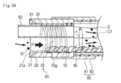
- the holding unit 40 is located on the same plane as the cutting end 21 or at a position farther from the constriction S than the cutting end 21 according to the pressing force. Holding is performed to move the tip portion 31) of the portion 30 (see FIG. 5A).
- the protection unit 30 moves to the same plane as the cutting end 21 or to a position farther from the constriction S than the cutting end 21, the cutting end 21 can come into contact with the constriction S. A cutting force can be applied.
- the protection unit 30 has a property (state) that can prevent the cutting end 21 from coming into contact with a living tissue or the like, and a property (state) that can cut the narrowed portion S by the cutting end 21. It has a function to switch reversibly.
- switching properties does not only mean switching between the properties that can be cut by the cutting end 21 and the properties that prevent the cutting end 21 from contacting the living tissue. It means broadly to switch the influence on the tissue or stenosis S. For example, as will be described in a later-described modification, the cutting end 21 itself can cut the narrowed portion S, and the member can have the cutting portion 21 other than the cutting end 21 cut. Switching is also included in the above “switching properties”.
- the protection unit 30 can be configured to protrude 0.5 mm from the cutting end 21 in a state where no load is applied from the outside, for example. Moreover, when moving to the position away from the narrowing part S rather than the cutting end 21 with the pressing with respect to the narrowing part S, it can comprise so that it may be 0.3 mm away from the cutting end 21, for example. In addition, these illustrated dimensions are examples, and are not particularly limited to these dimensions.
- the rotation receiving portion 50 includes a distal end opening 51, a proximal end opening 53, a lumen 55 connected between the distal end opening 51 and the proximal end opening 53, and side surfaces. And arranged side holes 56.
- a stepped portion where the wall thickness of the tube wall is thinner than other portions is provided on the inner surface on the tip side of the rotation receiving portion 50.
- the base end portion of the rotating body 20 is inserted into the stepped portion.
- the arrangement and fixing structure of the rotating body 20 and the tube 80 in the rotation receiving portion 50 can be changed as appropriate.
- a stepped portion is not provided in the rotation receiving portion 50, a tube 80 is inserted into the rotation receiving portion 50, a stepped portion is provided by narrowing the inner diameter of the rotation receiving portion 50 with the tube 80, and the rotating body 20 is inserted into this stepped portion.
- the base end portion of the rotating body 20 is supported by the inner surface of the rotation receiving portion 50. Since the base end portion of the rotating body 20 is supported by the rotation receiving portion 50, the rotating shaft of the rotating body 20 is stabilized, so that the rotating body 20 rotates smoothly. In addition, since the rotation receiving part 50 is not fixed to the rotating body 20, the rotation receiving part 50 does not rotate when the rotating body 20 rotates.
- the distal end of the tube 80 is inserted into the proximal end side of the rotation receiving portion 50.
- the distal end of the tube 80 (the distal end of the outer layer 82) is fixed to the inner surface of the rotation receiving portion 50.
- the tube 80 and the rotating body 20 can be fixed by, for example, a method such as adhesion using an adhesive, fusion, or welding.
- the tube 80 has a tube main body 81 and an outer layer 82 that covers the tube main body 81.
- the first slit 81a is disposed on the distal end side of the tube body 81, and the second slit 81b is disposed on the proximal end side of the first slit 81a.
- the first slit 81a has a smaller slit interval than the second slit 81b. Since the first slit 81a is arranged on the distal end side of the tube main body 81, the distal end side can be bent with a relatively large curvature. On the other hand, the proximal end side of the tube main body 81 can be bent with a relatively small curvature because the second slit 81b is arranged.
- the tube body 81 can be made of, for example, a known metal material or a hard resin material.
- the outer layer 82 adds flexibility to the tube 80 and further protects the living tissue when the living tissue comes into contact with the tube 80. Further, the outer layer 82 prevents the debris D and the like flowing into the tube 80 from being discharged from the tube 80.
- a hollow tube made of a known resin material such as polyethylene, polypropylene, or polyamide can be used.
- the cutting assisting portion 60 is disposed so that the distal end protrudes from the distal end of the protection portion 30, and the proximal end is fixed to the proximal end portion of the holding portion 40.
- the base end of the cutting assisting part 60 is fixed to the inner surface of the holding part 40 via a fixing part b3.
- the fixing at the fixing part b3 can be performed by, for example, a method such as adhesion with an adhesive, fusion, or welding.
- the proximal end of the cutting assisting portion 60 is fixed at a position closer to the proximal end side than the expansion / contraction deformation portion 35 of the protection portion 30, when the cutting assisting portion 60 is pressed against the constriction S, the expansion / contraction deformation portion 35 is excessively moved. It is possible to prevent excessive force from being applied. Thereby, it is possible to suitably prevent the expansion / contraction deformation portion 35 from being damaged.
- the cutting auxiliary part 60 is hollow. Moreover, as shown to FIG. 3A, it has the substantially U-shaped shape by which the notch was provided in a part of the circumferential direction in front view.
- the cutting assisting part 60 is disposed so as to protrude from the distal end part 31 of the protection part 30 regardless of the expansion / contraction deformation (deformation in the axial direction) of the holding part 40. .
- the cutting assisting portion 60 has a cutting force compared to the cutting end 21 of the rotating body 20 having the saw-toothed blade surface 21a so that the biological tissue is not inadvertently damaged by the cutting assisting portion 60.
- the shape and size of the cutting assisting part 60 and the positional relationship between the cutting assisting part 60 and the protection part 30 are not limited to those shown in the drawings, and can be changed as appropriate.
- the cutting assisting part 60 is indirectly fixed to the rotating body 20 via the base end part of the holding part 40 (base end part 33 of the protection part 30).
- the holding unit 40 rotates in conjunction with the rotation, and the cutting assisting unit 60 also rotates.
- the cutting assisting part 60 enters the narrowed part S to be cut prior to the cutting end 21 and forms a cut in the narrowed part S.
- the narrowed portion S can be easily cut as compared with the case where the cut is not formed.
- the cutting assistance part 60 supports the rotator 20 with respect to the stenosis part S.
- the deviation of the rotation axis is suppressed. This makes it possible to efficiently perform the cutting with the cutting edge 21 of the rotating body 20 particularly when the stenosis S as a treatment target site is a calcified lesion.
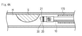
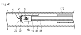
- FIGS. 4A to 4C and FIGS. 5A and 5B a treatment method using the medical device 1 will be described with reference to FIGS. 4A to 4C and FIGS. 5A and 5B.
- a method for cutting the constriction S formed in the blood vessel H will be described as an example.
- the guiding sheath 170 is introduced to the vicinity of the constriction S.
- the guiding sheath 170 can be delivered to the vicinity of the constriction S along a guide wire (not shown) introduced prior to the introduction of the guiding sheath 170. Note that when the guiding sheath 170 is delivered, the use of a guide wire can be omitted as appropriate.
- the medical device 1 is delivered to the vicinity of the stenosis S through the guiding sheath 170.
- the medical device 1 can be delivered along the guide wire by inserting the guide wire into the hub 151, the tube 80, the protection unit 30, and the holding unit 40.
- the protection unit 30 Is in a state of protruding from the cutting end 21 of the rotating body 20. Therefore, it is possible to prevent the cutting end 21 from inadvertently coming into contact with a normal living tissue on the blood vessel wall.
- the medical device 1 is pressed against the stenosis S from the distal end side while rotating the rotating body 20 as indicated by an arrow r.
- the pressing force f ⁇ b> 1 when the pressing force f ⁇ b> 1 is applied toward the proximal end by pressing the protection unit 30 against the narrowed portion S, the pressing force f ⁇ b> 1 holds the protection unit 30.
- the holding portion 40 contracts to the proximal end side.
- the protection unit 30 moves so as to be drawn into the rotating body 20.
- the tip of the protection part 30 moves to the same plane as the cutting end 21 or to a position farther from the constriction S than the cutting end 21, and when the cutting end 21 protrudes to the tip side from the protection part 30, Since a cutting force can be applied to the narrowed portion S from the cutting end 21, a narrowed object (for example, plaque or thrombus) in the narrowed portion S can be scraped off.
- a narrowed object for example, plaque or thrombus
- the suction device 190 shown in FIG. 1 is operated to suck the scraped constriction (debris) D into the rotating body 20.
- the debris D flows into the rotating body 20 through the distal end opening of the rotating body 20, and further moves toward the proximal end via the tube 80 communicating with the proximal end side of the rotating body 20. It is collected by the suction device 190.
- the convection induced by the rotation of the rotating body 20 amplifies the suction force that draws the debris D into the rotating body 20, so that the debris D moves smoothly toward the inside of the rotating body 20.
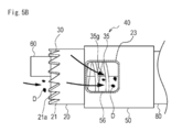
- the debris D passes through the side hole 56 arranged in the rotation receiving portion 50, the side hole 23 arranged in the rotating body 20, and the gap 35g arranged in the expansion / contraction deformation portion 35. Then, it is sucked into the protection unit 30.
- the debris D By sucking the debris D from the front end side of the rotating body 20 and the side surface side of the protection unit 30, the debris D can be efficiently collected, and the debris D as shavings stays around the rotating body 20. Can be prevented. For this reason, it is possible to prevent the debris D from adhering to the cutting end 21 of the rotating body 20 and to increase the cutting force that the cutting end 21 acts on the constriction S.
- the cutting assisting part 60 rotates in conjunction with the rotator 20 and applies a cutting force to the stenosis S on the tip side of the rotator 20. .
- the portion of the constriction S where the rotating body 20 applies the cutting force is in a state where cutting has been performed in advance by the cutting assisting unit 60. For this reason, since the narrowed portion S is brittle at the portion where the cutting end 21 of the rotating body 20 contacts, the rotation of the rotating body 20 can be prevented from being obstructed due to the contact, and cutting by the rotating body 20 can be performed. It becomes possible to proceed smoothly.
- the constricted portion S can be obtained by bringing the cutting end 21 of the rotating body 20 into contact with the portion where the auxiliary cutting is performed by the cutting assisting portion 60. It is possible to apply a sufficient cutting force to.
- the drive shaft 10 when the drive shaft 10 rotates, the rotation axis thereof is shifted to a position eccentric from the central axis C ⁇ b> 1 of the tube 80.
- the reason for shifting to such an eccentric position is that the drive shaft 10 is fixed to the inner surface of the rotating body 20 located on the outer peripheral side of the center axis C1 of the tube 80.
- the rotational trajectory of the drive shaft 10 is an elliptical trajectory indicated by an arrow r1.
- the drive shaft 10 applies a shearing force to the debris D flowing into the rotating body 20 and the tube 80 while rotating while drawing an elliptical orbit.
- the debris D is finely crushed by the action of this shearing force.
- the medical device 1 is moved to the distal end side by pressing the cutting end 21 of the rotating body 20 against the narrowed portion S. By performing this operation, the narrowed portion S can be cut along the extending direction. After confirming that the cutting treatment for the stenosis S has been completed, the medical device 1 is appropriately removed from the living body. In addition, it is also possible to continue the cutting treatment with respect to the other constricted part S.
- the medical device 1 includes the drive shaft 10 that can be rotated, and the cutting end 21 that applies a cutting force to the constriction S, and is disposed on the distal end side of the drive shaft 10 so as to be driven.
- Rotating body 20 rotated with the rotation of 10, property switching unit 30 disposed at a position where the tip projects from cutting end 21, and pressing force when property switching unit 30 is pressed against stenosis S
- a holding portion 40 that holds the property switching portion 30 so as to move to a position that is on the same plane as the cutting end 21 or that is farther from the constriction S than the cutting end 21 is provided.
- the cutting end without removing the medical device 1 from the blood vessel H by adjusting the pressing force that presses the property switching unit 30 against the stenosis S to be cut.
- the properties of 21 can be easily switched. Thereby, the effort which switches the property of the cutting edge 21 can be saved, and it becomes possible to implement a procedure smoothly and rapidly.
- the therapeutic effect of the procedure using the medical device 1 can be improved.
- the property switching unit 30 is configured as a protection unit 30 that protects the cutting end 21
- the pressing force that presses the protection unit 30 against the narrowed portion S to be cut is adjusted to adjust the rotation of the rotating body 20. Switching between the state in which the protective portion 30 protrudes from the cutting end 21 and the state in which the protective portion 30 moves to a position on the same plane as the cutting end 21 or farther from the constricted portion S than the cutting end 21 is possible. it can.
- the protection part 30 project from the cutting end 21, it is possible to prevent the cutting end 21 from inadvertently coming into contact with a living tissue (for example, a normal living tissue) other than the constriction. This eliminates the need for the surgeon to pay excessive attention when performing the procedure. As a result, it is possible to realize a quick treatment and reduce the burden on the patient associated with the treatment.
- a rotation receiving portion 50 having a lumen 55 communicating with the inside of the rotating body 20 is disposed at the base end of the rotating body 20, and the holding portion 40 is expanded and contracted along the extending direction of the rotation receiving portion 50. It is configured to be possible. For this reason, the position protruding from the cutting end 21 by the expansion and deformation of the holding unit 40 in conjunction with the operation of pressing the protection unit 30 against the constriction S and the operation of releasing the pressed state, and the cutting end It is possible to reversibly move the protection unit 30 to the same plane as 21 or to a position farther from the constriction S than the cutting end 21.
- the rotation receiver 50 has a cylindrical shape including a distal end opening 51, a proximal end opening 53, and a lumen 55 connected to the distal end opening 51 and the proximal end opening 53.
- the protection part 30 is configured to be movable in the inner and outer directions (axial direction) of the rotation receiving part 50 by expansion and contraction of the holding part 40. For this reason, the protection part 30 can be moved in and out of the rotation receiving part 50 in accordance with the expansion and contraction of the holding part 40, and the amount of protrusion of the protection part 30 from the rotation receiving part 50 is adjusted, so that the rotating body 20 It is possible to switch between a state in which cutting by the cutting end 21 is possible and a state in which cutting by the cutting end 21 is restricted.
- the holding portion 40 is constituted by a hollow spring, and the protection portion 30 is integrally provided at the distal end portion of the holding portion 40. For this reason, it becomes possible to move the holding part 40 easily by elastically deforming the spring. Moreover, since the protection part 30 and the holding
- a side hole 56 is disposed on the side surface of the rotation receiving portion 50 to communicate the inside of the holding portion 40 and the outside of the rotation receiving portion 50.
- the medical device 1 further includes a cutting assisting portion 60 that is disposed on the rotating body 20 and assists cutting by the cutting end 21, and the distal end side of the cutting assisting portion 60 protrudes from the distal end of the protection portion 30.
- the base end side of the cutting assisting part 60 is fixed to the base end side of the holding part 40. For this reason, the cutting efficiency of the constriction S can be increased by the cutting assisting portion 60.
- the cutting end 21 provided in the rotating body 20 has a blade surface 21a having a shape that is notched in a concavo-convex shape, the narrowed portion S can be finely crushed. Even in the case where the lesion is a morphological lesion, the narrowed portion S can be efficiently cut.
- the property switching unit 30 is protruded from the distal end side of the rotating body 20 including the cutting end 21 that applies a cutting force to the constriction S, and the property switching unit 30 is formed in the stenosis S.
- the property of the cutting edge 21 is switched by adjusting the pressing force that presses the property switching unit 30 against the narrowed portion S to be cut. It is possible to proceed with the treatment while appropriately switching the properties of the cutting edge 21 according to the properties of the constriction S. Therefore, according to this method, it is possible to perform a smooth and quick procedure and improve the treatment effect.
- the property switching unit 30 is configured by the protection unit 30 so that the protection unit 30 protrudes from the cutting end 21, so that the cutting end 21 is inadvertently brought into contact with a living tissue other than the stenosis S. Can be prevented. Then, the protection part 30 is pressed against the constriction S and moved to the same plane as the cutting end 21 or to a position farther from the object than the cutting end 21, so that the treatment by the cutting end 21 can be performed. According to this method, since it is not necessary for the surgeon to pay excessive attention when performing the treatment, a rapid treatment can be realized, and the burden on the patient associated with the treatment can be reduced.
- the step of moving the protection unit 30 includes contracting and deforming the holding unit 40 for holding the protection unit 30 along the extending direction of the rotation receiving unit 50 including the lumen 55 communicating with the inside of the rotating body 20. Done. For this reason, the holding part 40 can be expanded and contracted in conjunction with an operation of pressing the protective part 30 against the narrowed part S and an operation of releasing the pressed state, and the protective part 30 can be moved reversibly. Is possible.
- the holding part 40 is disposed inside the rotation receiving part 50, and the protection part 30 is configured to be movable inward and outward of the rotation receiving part 50 by expansion and contraction of the holding part 40. .
- the protection part 30 can be moved into and out of the rotation receiving part 50 along with the expansion and contraction of the holding part 40, and the protruding amount of the protection part 30 from the rotation receiving part 50 is adjusted to cut the cutting end 21. It is possible to switch between a state in which cutting can be performed and a state in which cutting by the cutting end 21 is restricted.
- the holding part 40 is constituted by a hollow spring, and the protection part 30 is integrally provided at the tip of the holding part 40. For this reason, it becomes possible to move the holding part 40 easily by elastically deforming the spring. Moreover, since the protection part 30 and the holding
- the method further includes a step of introducing the cut debris D into the inside of the rotation receiving portion 50 and the inside of the holding portion 40 through the side hole 56 disposed on the side surface of the rotation receiving portion 50. For this reason, the debris D generated when the narrowed portion S is cut can be efficiently collected into the holding portion 40. Thereby, it is possible to suppress a reduction in cutting force due to the generation of debris D.
- the cutting step includes a step of cutting the constricted portion S while assisting the cutting by the cutting end 21 by the cutting auxiliary portion 60 disposed in the rotating body 20. For this reason, cutting of the constricted portion S can be assisted by the cutting assisting portion 60, and the cutting efficiency by the cutting end 21 of the rotating body 20 can be increased. In particular, when the calcification of the narrowed portion S progresses and the hardness is high, the cutting assist function by the cutting assisting portion 60 is satisfactorily exhibited.
- the protection unit 130 is disposed on the outer surface of the rotating body 20.
- the protection part 130 is comprised by the substantially cylindrical elastic member.
- the elastic member for example, resin rubber, sponge, elastically deformable metal, or the like can be used.
- the elastic member constituting the protection unit 130 also has a function as the holding unit 40 that holds the protection unit 130.
- the base end part of the protection part 130 can be fixed to the outer surface of the base end part of the rotation receiving part 50, for example. Fixing can be performed, for example, by a method such as adhesion, fusion, or welding with an adhesive. Since the protection unit 130 is not fixed to the rotating body 20, the protection unit 130 is not rotated in conjunction with the rotation of the rotating body 20.
- the protection part 130 can make a part of the thickness in the circumferential direction thicker than the other part.
- the lower portion (bottom surface side) 130b in the circumferential direction is thicker than the upper portion 130a.
- the thick part 130b of the protection part 130 is less likely to have the cutting force of the cutting edge 21 when the narrowed part S is cut, and the cutting is suppressed. Therefore, since the cutting on the side of the portion 130a where the thickness of the protective portion 130 is thin proceeds preferentially, the traveling direction of the rotating body 20 is guided to the inside of the constricted portion S (outward side as viewed from the center of the blood vessel). .
- the thick portion 130b of the protection unit 130 is, for example, disposed at least on a part of the protection unit 130 located on the vertical downward side when viewed from the central axis of the protection unit 130 on the cross section perpendicular to the axis.
- the function of guiding the moving direction of the rotating body 20 can be exhibited. For this reason, there is no particular limitation as to what range the arrangement is made.
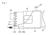
- the protection portion 230 is configured by an elastic member that can be externally mounted on the outer surface of the rotation receiving portion 50.
- the elastic member for example, resin rubber, sponge, elastically deformable metal, or the like can be used.
- the protective part 230 has a hollow inside and is externally covered so as to cover the base end part of the rotation receiving part 50.
- the protection part 230 has an inclined notch that exposes a part of the side hole 56 of the rotation receiving part 50 to the outside in a state where the protection part 230 is externally mounted on the rotation receiving part 50.
- the bottom part 230b located at the front end of the protection part 230 protrudes toward the front end side.
- the bottom portion 230b has a function of preventing the cutting end 21 of the rotating body 20 from coming into contact with a living tissue other than the constriction S.
- the base end of the protection unit 230 has a function as the holding unit 40 that holds the protection unit 230 against the rotation receiving unit 50.
- the protection unit 230 Since the protection unit 230 is not fixed to the rotating body 20, the protection unit 230 is not rotated in conjunction with the rotation of the rotating body 20.
- the structure of the protection unit and the holding unit prevents the cutting end at the tip of the rotating body from inadvertently contacting a portion other than the constriction (object).
- the specific configuration is not particularly limited as long as the cutting end can be switched to a state in which the cutting end can be brought into contact with the object by being pressed against the object.
- the cutting end 121 of the rotating body 120 is provided with a tapered blade surface 121 a that becomes thinner toward the tip end side of the rotating body 120.
- the blade surface 121a may have the same shape as, for example, a trepan blade surface (having a tapered shape that tapers toward the distal end side and has a smooth distal end surface) used for biopsy instruments in the medical field. it can.
- a trepan blade surface having a tapered shape that tapers toward the distal end side and has a smooth distal end surface
- a cutting portion 331 for applying a cutting force to the narrowed portion S is provided at the tip of the property switching portion 330. Since the cutting part 331 is provided in the property switching part 330, the narrowing part S can be cut by pressing the property switching part 330 against the narrowing part S.
- the cutting by the cutting unit 331 can be performed, and the property switching unit 330 can be set by increasing the pressing force against the stenosis S.
- the property switching unit 330 switches between the property (state) of cutting at the cutting end 21 of the rotating body 20 and the property (state) of cutting at the cutting unit 331 of the property switching unit 330. It has a function.
- the blade surface 331a of the cutting unit 331 of the property switching unit 330 can be constituted by a trepan blade surface, for example. Further, when the blade surface 331a is constituted by a trepan blade surface, for example, the blade surface 21a of the cutting end 21 of the rotating body 20 can be constituted by a saw-toothed blade surface.
- the treatment which cuts off the soft tissue constriction part S with the blade surface 331a with which the property switching part 330 is equipped, and the calcified lesion part with the blade surface 21a with which the rotary body 20 is provided. It is possible to realize the procedure of finely crushing with one medical device.
- the blade surface 331a of the property switching unit 330 that applies cutting force to the constriction S in advance is constituted by a trepan blade surface
- the constriction S is cut by the blade surface 331a.
- the blade surface 21a configured in a saw-tooth shape can be made to enter the cut portion. Since it becomes easy for the blade surface 21a to enter the narrowed portion S, the narrowed portion S can be more finely crushed by the blade surface 21a, and the therapeutic effect can be improved.
- the blade surface 331a of the property switching unit 330 located on the tip side of the rotating body 20 is configured with a smooth blade surface such as a trepan blade surface, the safety of the blood vessel wall and the like is improved.
- the shape of the blade surface 21a included in the rotating body 20 and the shape of the blade surface 331a included in the property switching unit 330 are not limited to those illustrated, and can be changed as appropriate.
- both the blade surfaces 21a and 331a are configured with a saw-toothed blade surface or a trepan blade surface, or the blade surface 331a provided in the property switching unit 330 is configured with a saw-toothed blade surface and the blade surface provided in the rotating body 20 It is also possible to configure 21a with a trepan blade surface.
- the position of the distal end of the cutting assisting unit 60 is located on the proximal side with respect to the property switching unit 30. Is adopted. Even in such an arrangement, the cutting assisting portion 60 can be protruded from the tip of the property switching portion 30 by adjusting the pressing force that presses the property switching portion 30 against the narrowed portion S. It becomes possible to carry out cutting.
- the property switching unit 30 functions as a protection unit, and it is possible to prevent the cutting assisting unit 60 from inadvertently contacting the living tissue. Therefore, the safety during use is further improved.
- the safety during use can be kept very high even when the cutting auxiliary portion 60 is provided with a saw-like blade surface with a relatively high cutting force. For this reason, the range of design freedom of the structure and shape of the cutting assisting portion 60 is widened, and the cutting assisting portion 60 can be provided with various functions.
- the tip of the cutting assisting unit 60 may be disposed, for example, closer to the tip side than the tip of the cutting end 21, or substantially the same as the tip of the cutting end 21. You may arrange
- a chamfered portion 161 a that is chamfered in an R shape is provided at the tip 161 of the cutting assisting portion 160. Since the chamfered portion 161a is provided in the cutting assisting portion 160, when the cutting is performed by rotating the rotating body 20, the trajectory r2 drawn by the cutting assisting portion 160 is curved from the distal end side toward the proximal end side. (Dome shape). Even if the cutting assisting part 60 may come into contact with the blood vessel wall or the like during the treatment, it is possible to prevent a scratching force from acting on the blood vessel wall. It becomes possible to further increase.
- curvature of the chamfered portion 161a is not particularly limited, and can be changed as appropriate.
- FIG. 12 is a plan view showing the overall configuration of the medical device 100 according to this modification
- FIG. 13A is an enlarged cross-sectional view around the proximal end portion
- FIG. 13B is an enlarged cross-sectional view around the distal end portion.
- the coil 90 is inserted through the lumen 85 of the tube 80.
- the rotating body 20 is attached to the tip of the coil 90.
- a rotation receiving portion 50 is attached to the tip of the tube 80.
- a relay tube 95 is attached to the proximal end of the tube 80.
- the proximal end of the coil 90 is attached to the inner surface of the distal end of the relay tube 95.
- the hub 151 is attached so as to surround the outer periphery of the relay tube 95. As shown in FIG. 12, the proximal end portion of the relay tube 95 is led out from the hub 151 through the proximal end port 152 of the hub 151. Further, the relay tube 95 is inserted through a valve element 157 disposed inside the hub 151.
- the relay tube 95 is provided with an opening 96.
- the lumen 95 a of the relay tube 95 communicates with the inside of the connector portion 153 provided on the hub 151 through the opening 96.
- Debris D and the like generated in the treatment using the medical device 100 can be discharged from the relay tube 95 to the outside through the lumen 95a and the opening 96 of the relay tube 95.
- the coil 90 is covered with a tube 80.
- the tube 80 prevents the sucked fluid, debris D, and the like from leaking through the gap of the coil 90.
- the tube 80 can be constituted by, for example, a single-layer resin tube made of a known resin material.
- the relay tube 95 is configured to be rotatable by a rotational driving force transmitted from the external driving device 180.
- the external driving device 180 is provided with a second moving mechanism 186 a that applies a rotational driving force to the relay tube 95 in cooperation with the first moving mechanism 86 a provided on the relay tube 95.
- the first moving mechanism 86a can be configured by, for example, a driven gear
- the second moving mechanism 186a can be configured by, for example, a driving gear that meshes with the driven gear.
- the external driving device 180 includes a known driving unit such as an electric motor including a driving shaft.
- the drive gear (second movement mechanism) 186a rotates and is driven by the rotation of the drive gear 186a to follow the driven gear (first gear).
- the moving mechanism) 86a rotates.
- the driven gear 86a rotates, the relay tube 95 rotates in conjunction with the rotation (indicated by an arrow r11 in FIG. 13A).
- the coil 90 attached to the relay tube 95 rotates (rotation is indicated by an arrow r13 in FIGS. 13A and 13B). And if the coil 90 rotates, the rotary body 20 arrange
- a valve body 158 is disposed at the proximal end of the relay tube 95.
- the valve body 158 is provided with an insertion hole 159 through which the guide wire W is inserted.
- the guide wire W is inserted into the lumen 95 a of the relay tube 95 through the valve body 158.
- the guide wire W is inserted through the lumen 95a of the relay tube 95, the lumen 90a of the coil 90 disposed at the tip of the relay tube 95, the rotating body 20, and the property switching unit. It is guided to the inside of 30.
- the guide wire W is led out from the distal end opening of the property switching unit 30, and the distal end is guided to the distal end side of the rotating body 20. Since the guide wire W can be easily inserted from the proximal end to the distal end of the relay tube 95, the guide wire W can be operated smoothly when performing a treatment using the medical device 100.
- the cutting body 60 is not provided in the rotating body 20 so that the guide wire W can be inserted smoothly and easily inside the rotating body 20 and the property switching section 30. .
- the material and structure of the coil 90 and the relay tube 95 are not particularly limited as long as the coil 90 and the relay tube 95 can be configured to rotate the rotating body 20 in conjunction with the rotation.
- the method for fixing the coil 90 and the tube 80 and the fixing position, the method for fixing and fixing the relay tube 95 and the tube 80, the method for fixing the coil 90 and the relay tube 95, and the fixing position also transmit the rotational driving force to the rotating body 20.
- a cylindrical rotating body having a cutting end formed on the tip surface is exemplified.
- the configuration of the rotating body is particularly limited as long as cutting by the cutting end is possible.
- the cutting end may be formed not on the front surface of the rotating body but on the side surface of the rotating body.
- the shape and material of additional members such as the rotation receiving portion and the cutting assisting portion can be appropriately changed according to the product specifications of the medical device, and are not limited to the configuration described above. Absent.
- the medical device 2 according to the second embodiment will be described. Note that description of members and the like that can be configured similarly to the medical device 1 and the medical device 100 according to the first embodiment described above in the description of the second embodiment is omitted as appropriate. In addition, structures and the like not particularly mentioned in the description of the second embodiment can be configured in the same manner as in the first embodiment.
- the medical device 2 according to the second embodiment is different from the medical device 1 described above in the structure on the distal end side of the tube 80. Specifically, when the medical device 2 performs a treatment on the stenosis S using the rotator 20, a tip for adjusting a contact position where the rotator 20 is brought into contact with the stenosis S is used. It has a member 400 (see FIG. 18B).
- the medical device 2 generally includes a rotatable drive shaft 10, a rotating body 20 that includes a cutting end 21 and is rotated as the drive shaft 10 rotates, and a protection unit (characteristic switching). Part) 30, a cutting assisting part 60, and a tip member 400 disposed on the rotating body 20.
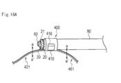
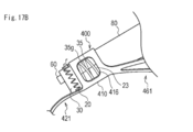
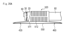
- the distal end member 400 extends to the distal end side from the distal end of the rotating body 20 and a hollow main body 410 having an inner cavity 415 and a side hole 416 opened in the side surface. And a support portion 420 configured to be able to support the rotating body 20 with respect to a living body lumen such as a blood vessel H.
- the rotating body 20 can be inserted and disposed in the main body 410 of the tip member 400.
- the main body 410 holds the rotating body 20 in the lumen 415.
- the main body 410 also has a function as a rotation receiver that prevents the rotation shaft of the rotating body 20 from shaking when the rotating body 20 rotates.
- the tip member 400 is attached to the outer surface of the rotating body 20.
- the support part 420 of the tip member 400 is disposed so as to extend further to the tip side than the tip of the rotator 20 in a state where the rotator 20 is inserted into the main body part 410 (see FIG. 14).
- the support section 420 is configured such that the distance between the support body 420 and the rotating body 20 is variable in a first direction that intersects the extending direction of the rotating body 20 (the direction of the arrow aa ′ in FIG. 15A).
- the first direction is set to a vertical direction (also referred to as “height direction”) orthogonal to the extending direction (axial direction) of the tip member 400.
- the first direction is not particularly limited as long as it is a direction in which the rotating body 20 is brought close to the narrowed portion S to be cut in the procedure using the medical device 2, and is not limited to the vertical direction.
- the support part 420 extends in a first direction so as to be gradually separated from the rotating body 20 and can be elastically deformed.
- the support part 420 extends further to the distal end side than the first part 421, and the guide wire W can be inserted therethrough.
- a second portion 422 having a guide wire insertion portion (lumen) 423.
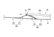
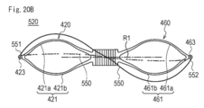
- the first portion 421 of the support portion 420 has a second direction (in the direction of the arrow bb ′ in FIG. 15B) that intersects each of the first direction and the extending direction of the rotating body 20 in the state where no external force is applied. ) Projecting outward from the rotating body 20.
- the second direction is set to a horizontal direction (also referred to as “width direction”) orthogonal to the first direction.
- the second direction is not particularly limited as long as the rotating body 20 can be positioned with respect to a predetermined position in the procedure using the medical device 2.
- the second direction is appropriately changed according to the change in the first direction. Can change.
- the first portion 421 has a shape that spreads in a symmetric direction with respect to the rotation axis R ⁇ b> 1 of the rotating body 20.
- part 421 is comprised by the 1st arm part 421a and the 2nd arm part 421b.
- the first arm portion 421a and the second arm portion 421b have substantially symmetric shapes with respect to the rotation axis R1.
- the proximal end of the first arm part 421a and the proximal end of the second arm part 421b are connected to the main body part 410, and the distal end of the first arm part 421a and the distal end of the second arm part 421b are connected to the second part 422. It is connected.
- An annular space is defined between the arm portions 421a and 421b.
- each arm portion 421a, 421b has a shape that is gently curved in a convex shape along the first direction from the main body portion 410 toward the distal end side.
- the tip side connected to the second part 422 is farthest from the main body 410.
- the distal end member 400 extends to the proximal end side from the proximal end of the rotating body 20 and is configured to be able to support the rotating body 20 with respect to the blood vessel H. It has further.
- the auxiliary support portion 460 has a shape that is substantially symmetrical to the support portion 420 with respect to the center position of the main body portion 410. Similar to the support part 420, the auxiliary support part 460 has a distance from the rotary body 20 in the first direction (the direction of the arrow aa ′ in FIG. 15A) intersecting the extending direction of the rotary body 20. It is configured to be variable.
- the auxiliary support part 460 extends in a first direction so as to be gradually separated from the rotating body 20 and is elastically deformable.
- the auxiliary support part 460 extends closer to the proximal end side than the first auxiliary part 461, and is a guide wire.
- a second auxiliary portion 462 having a guide wire insertion portion (lumen) 463 through which W can be inserted.
- the first auxiliary portion 461 of the auxiliary support portion 460 has a shape that protrudes outward from the rotating body 20 in the second direction (the direction of the arrow bb ′ in FIG. 15B) when no external force is applied. ing.
- the first auxiliary portion 461 has a shape spreading in a symmetric direction with respect to the rotation axis R1 of the rotating body 20.
- the first auxiliary portion 461 includes a first arm portion 461a and a second arm portion 461b.
- the 1st arm part 461a and the 2nd arm part 461b are comprised by each of the arm parts 421a and 421b with which the support part 420 is provided, the description about a shape is abbreviate
- the main body portion 410, the support portion 420, and the auxiliary support portion 460 of the tip member 400 can be integrally formed of, for example, a known metal material or resin material.
- the above-described parts are integrally formed of a metal having biocompatibility.
- the main body 410, the support 420, and the auxiliary support 460 are integrally formed by covering the outer surface with a resin coating member (for example, a well-known heat shrink tube) or the like, and thermally contracting the coating member. It is possible to connect.
- a resin coating member for example, a well-known heat shrink tube
- the first part 421 of the support part 420 and the first auxiliary part 461 of the auxiliary support part 460 can be composed of, for example, a flat plate member. Further, the second part 422 of the support part 420 and the second auxiliary part 462 of the auxiliary support part 460 can be configured by, for example, a cylindrical member having a hollow inside.
- the tip member 400 is attached to the outer surface of the rotating body 20 during the treatment using the medical device 2.
- the support part 420 (first part 421) and the auxiliary support part 460 (first auxiliary part 461) of the tip member 400 generate tension that raises (lifts) the rotating body 20 upward (in the direction of arrow a in the figure).
- the position where the tip member 400 is attached to the rotating body 20 can be appropriately set to a position where the cutting end 21 of the rotating body 20 is not covered by the tip of the tip member 400.
- the distance (height) which raises the rotary body 20 can be set within 7 mm, for example, when applying the medical device 2 to the treatment to the blood vessel H.
- the tip member 400 is externally mounted on the rotating body 20, it is not necessary to house or insert the support portion 420 and the auxiliary support portion 460 included in the tip member 400 inside the rotating body 20. For this reason, it is possible to avoid an increase in diameter of the rotating body 20 itself, and a decrease in the deliverability in the blood vessel H and a decrease in the insertability into the stenosis S due to the increase in the diameter of the rotating body 20 occur. Can be prevented.
- a curved shape is added to the distal end portion 88a of the tube 80.
- the direction of the tip surface of the rotating body 20 is prevented from tilting upward or downward.
- the first part 421 of the support portion 420 and the auxiliary part are supported by the elasticity of the guide wire W.
- the first auxiliary portion 461 of the support portion 460 may be curved so as to follow the bending of the guide wire W.
- the direction of the tip surface of the rotating body 20 indicated by the arrow e is inclined upward or downward, and the direction of the cutting end 21 may be unintended.
- the distal end portion 88a of the tube 80 by adding a predetermined curved shape to the distal end portion 88a of the tube 80 so that the orientation of the rotating body 20 can be kept facing the front, It becomes possible to adjust the direction to face the front side.
- the state shown in FIG. 17A is switched to the state shown in FIG. 17B according to the rotation of the rotating body 20.
- the state shown in FIG. 17A is a state in which the inflow of debris D from the side surface of the rotating body 20 is prevented
- the state shown in FIG. 17B is a state in which the debris D can be introduced from the side surface of the rotating body 20. is there.
- FIGS. 18A to 18C a treatment method using the medical device 1 will be described with reference to FIGS. 18A to 18C.
- a method for cutting the constriction S formed in the blood vessel H will be described as an example.
- the guiding sheath 170 is introduced to the vicinity of the constriction S.
- the guiding sheath 170 can be delivered to the vicinity of the constriction S along the guide wire W introduced in advance.
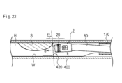
- the medical device 2 is delivered to the vicinity of the constriction S along the guide wire W.
- the distal end member 400 can be smoothly moved to a desired position by inserting the guide wire W through the second portion 422 of the support portion 420 and the second auxiliary portion 462 of the auxiliary support portion 460. become.
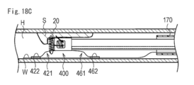
- the tip member 400 is pressed against the inner wall of the guiding sheath 170 to be in the height direction (the direction of arrow a ′ in FIG. 15) and the width direction (the arrow b in FIG. 15). Shrink in the 'direction).
- the first portion 421 of the support portion 420 contacts the inner wall of the blood vessel H. It deforms so as to spread in the height direction and the width direction until it touches. Similarly, the first auxiliary portion 461 of the auxiliary support portion 460 is deformed so as to expand in the height direction and the width direction until it contacts the inner wall of the blood vessel H.
- the rotating body 20 to which the tip member 400 is attached is arranged at a position facing the stenosis S formed on the inner wall of the blood vessel H by being raised in the height direction.
- the rotating body 20 is disposed at a position where the rotation axis R1 overlaps the guide wire insertion portions 423 and 463 by the first portion 421 and the first auxiliary portion 461 that are widened in the width direction (see FIG. 15B). .
- the rotation axis R1 passing through the center of the tip member 400 is arranged substantially parallel to the travel of the guide wire W.
- the rotating body 20 is adjusted in the height direction and the width direction of the blood vessel H (the height direction and the width direction on the cross section perpendicular to the axis) as appropriate, and then the rotator 20 is placed on the constricted portion S to be cut. Because of the contact, the cutting force by the cutting end 21 can be applied to the constricted portion S satisfactorily, and the constricted portion S can be cut efficiently.
- the first portion 421 of the support portion 420 and the first auxiliary portion 461 of the auxiliary support portion 460 are elastically deformed following the inner diameter of the blood vessel H, the first portion 421 and the first portion 421 in a state where no external force is applied. Even when the blood vessel H having a smaller inner diameter or the like than the one auxiliary portion 461 is a treatment target, the distal end member 400 can be reduced in diameter and moved in the blood vessel H. The delivery in is good.
- the narrowed portion S is cut by moving the medical device 2 to the distal end side by pressing the cutting end 21 of the rotating body 20 against the narrowed portion S.
- the suction device 190 is operated to suck the scraped debris D into the rotating body 20.
- the medical device 2 After finishing the cutting treatment for the stenosis S, the medical device 2 is appropriately removed from the living body. It is also possible to continue the cutting treatment for the other narrowed portion S.
- the medical device 2 includes the drive shaft 10 that can rotate and the cutting end 21 that applies a cutting force to the constriction S, and is disposed and driven on the distal end side of the drive shaft 10. It has the rotary body 20 rotated with rotation of the shaft 10, and the front-end
- the distal end member 400 has a support portion 420 that extends to the distal end side relative to the distal end of the rotating body 20 and is configured to be able to support the rotating body 20 with respect to the blood vessel H. In the first direction (height direction) in which the rotating body 20 approaches S, the distance from the rotating body 20 is configured to be variable.
- the rotating body 20 is positioned with respect to the stenosis part S in the blood vessel H by being supported by the support part 420. Since the cutting end 21 comes into contact with the stenosis S with the rotating body 20 positioned at the stenosis S, a cutting force can be applied to the stenosis S satisfactorily. As a result, the stenosis portion S can be efficiently cut, and the cutting end 21 can be suitably prevented from coming into contact with a living tissue other than the stenosis portion S.
- the support portion 420 extends in the first direction so as to be gradually separated from the rotating body 20 and is elastically deformable, and extends to the tip side of the first portion 421.
- the guide wire W And a second portion 422 including a guide wire insertion portion 423 that can be inserted are used to insert the rotating body 20 to be easily aligned with the narrowed portion S by utilizing the elastic deformation of the first portion 421.
- the distal end member 400 of the medical device 2 can be delivered to a desired position in the living body, so that the operability is excellent.
- the first portion 421 has a shape protruding outward from the rotating body 20 in the second direction intersecting each of the first direction and the extending direction of the rotating body 20 in a state where no external force is applied. is doing. For this reason, the first portion 421 easily comes into contact with the inner wall of the blood vessel H, and the tip member 400 can be supported on the inner wall of the blood vessel H by this contact. Since the tip member 400 is supported by the inner wall of the blood vessel H, it is possible to prevent the rotating shaft of the rotating body 20 from moving when the stenosis part S is cut, so that the stenosis part S can be cut efficiently. become.
- the center position of the tip member 400 is positioned with respect to the rotation axis R1 of the rotating body 20. Further, since the center position of the tip member 400 can be aligned with the center position in the width direction of the blood vessel H, the stenosis S can be cut more efficiently.
- the distal end member 400 further includes an auxiliary support portion 460 that extends to the proximal end side from the proximal end of the rotating body 20 and is configured to be able to support the rotating body 20 with respect to the blood vessel H.
- the tip member 400 can be raised at the distal end side and the proximal end side of the tip member 400, so that the tip member 400 can be raised more reliably and when it is raised.
- it is possible to prevent a gap in the height direction from being generated between the distal end side and the proximal end side of the distal end member 400 it is possible to appropriately align the rotating body 20 with respect to the narrowed portion S.
- the auxiliary support part 460 extends to the proximal end side relative to the first auxiliary part 461 and the first auxiliary part 461 that is elastically deformable and extends so as to be gradually separated from the rotating body 20 in the first direction.
- the tip member 400 can be smoothly moved to a desired position by the guide wire W inserted into the second auxiliary portion 462 of the auxiliary support portion 460 and 422.
- a rotating body 20 including a cutting end 21 that applies a cutting force to the stenosis S in the blood vessel H is supported in a first direction (height direction) that approaches the stenosis S. And a cutting process in which the cutting end 21 is brought into contact with the constriction S while the rotating body 20 is rotated.
- the rotator 20 is supported, the position of the rotator 20 is adjusted with respect to the stenosis S in the blood vessel H, and then the stenosis S of the rotator 20 is adjusted. Cut. Thereby, it becomes possible to make a cutting force act favorably with respect to the stenosis part S, and also it becomes possible to prevent suitably that the cutting end 21 contacts biological tissues other than the stenosis part S.
- the cutting process is performed in a state in which the rotating body 20 is supported in the second direction (width direction) intersecting each of the first direction and the extending direction of the rotating body 20, the distal end member 400 is moved more in the blood vessel H. It can be supported in a stable state, and the rotating shaft of the rotating body 20 can be prevented from shaking when the constricted portion S is cut. Thereby, it becomes possible to cut the narrowed portion S efficiently.
- the cutting process is performed in a state where the rotating body 20 is supported by the support portion 420 extending to the distal end side of the rotating body 20 and the auxiliary support portion 460 extending to the proximal end side of the rotating body 20.
- the tip member 400 can be lifted more reliably, and when the tip member 400 is lifted, a gap in the height direction is generated between the tip side and the base end side of the tip member 400. Can be prevented. For this reason, it becomes possible to appropriately align the rotating body 20 with respect to the narrowed portion S.
- the said treatment method has the suction process which attracts the cut debris D in the rotary body 20, the debris D can be rapidly discharged
- the tip member 510 includes a link structure 512 for maintaining the orientation of the tip surface of the rotating body 20 indicated by an arrow e in a predetermined direction.
- the link structure 512 can be configured by a slit disposed in the main body 511 of the tip member 510, for example. Due to the link structure 512, the tip member 510 has a shape in which the central portion on the lower surface side is warped to the upper surface side.
- the rotating body 20 inserted into the main body 511 has a distal end surface below the position parallel to the travel of the blood vessel H (the side away from the stenosis S, as shown in FIG. It is prevented from facing toward the lower side. Thereby, it becomes possible to prevent the cutting end 21 from coming into contact with a living tissue other than the constriction S.
- the guide wire insertion portion 423 is configured by a through hole disposed at the distal end of the support portion 420, and the guide wire insertion portion 463 is a through hole disposed at the proximal end of the auxiliary support portion 460. It is constituted by. Even when the guide wire insertion portions 423 and 463 are configured by the through holes arranged in the respective support portions 420 and 460, the rotating body 20 using the guide wire W can be delivered and moved smoothly. Further, the tip member 510 can be reduced in size compared to the case where hollow members such as the second part 422 and the second auxiliary part 462 shown in the above-described embodiment are used, and the number of parts can be reduced. The manufacturing cost can be reduced by the reduction.
- the tip member 520 according to the second modification has an elastically deformable connection portion 550 connected to the support portion 420 and the auxiliary support portion 460.
- connecting portion 550 is outward from support portion 420 and auxiliary support portion 460 in the direction intersecting the extending direction of rotating body 20 (vertical direction in FIG. 20B). It has a protruding shape.
- connection portion 550 has a shape in which a distal end portion 551 connected to the support portion 420 and a proximal end portion 552 connected to the auxiliary support portion 460 spread in a direction symmetrical to the rotation axis R1 of the rotating body 20.
- the connection portion 550 has an S shape in plan view, but is not limited thereto.
- the connection part 550 may have an 8-shaped shape in plan view.
- the connecting portion 550 can be constituted by, for example, an elastically deformable metal wire or a resin wire.
- FIG. 20C schematically shows a cross section perpendicular to the axis of the blood vessel H.
- the illustrated blood vessel H is, for example, a flat blood vessel H in which the size of the lumen in the vertical direction is long and the size of the lumen in the horizontal direction is short.
- the connecting portion 550 spreads in the short axis direction (left and right direction in the drawing) of the blood vessel H, so that the center position of the distal end member 520, that is, the rotation center of the rotating body 20 is obtained. Is aligned with the center position of the blood vessel H in the minor axis direction.
- the connecting portion 550 When the connecting portion 550 is inserted into a guiding sheath or the like having an inner diameter smaller than the width of the connecting portion 550 in the expanded state (length in the vertical direction in FIG. 20B), it is indicated by a two-dot chain line in FIG. 20B.
- the width is reduced by elastically deforming into a substantially linear shape as shown. For this reason, the tip member 520 can be smoothly moved even within a relatively small guiding sheath.
- the tip member 530 according to the modification 3 includes a third portion 430 that extends between the first portion 421 and the second portion 422 in the support portion 420.
- the third part 430 is formed of a member that is more flexible than the second part 422.
- the third portion 430 can be configured by a bendable metal hollow member in which a slit is disposed, for example.
- the second portion 422 can be configured by a resin hollow member that is harder (rigid) than the third portion, for example.
- the third part 430 is connected to the second part 422 via a predetermined relay member 433.
- the relay member 433 can be constituted by, for example, a resin covering member (for example, a known heat shrinkable tube) that covers and integrally connects the second portion 422 and the third portion 430.
- the first part 421 and the third part 430 are appropriately connected using, for example, an adhesive.
- FIG. 21B shows a treatment example when the tip member 530 according to the modification 3 is used in the blood vessel H in which the branch blood vessel H1 exists on the distal side (tip side) of the stenosis S.
- the direction of the tip member 530 is affected by the bending, The posture, position, etc. may be corrected in the bending direction. Further, when the orientation of the tip member 530 is corrected, the cutting end 21 may be pressed against the blood vessel wall on the side where the stenosis S is formed with a force greater than expected.
- the third part 430 located on the proximal end side of the second part 422 is more flexible than the second part 422.
- a shape memory member is used for the tube 80 connected to the proximal end side of the distal end member 400.
- the tube 80 is configured to lift the tip member 400 by restoring to a pre-shaped shape.
- the tube 80 is preliminarily provided with a curved shape that lifts the tip member 400 in the height direction (upward in the figure) when it is led out from a guiding sheath or the like used in the procedure.
- the tube 80 is connected to, for example, a hollow long shape memory member 80a, a heat-shrinkable tube (not shown) arranged so as to cover the outer surface thereof, and a proximal end side of the shape memory member 80a. It is possible to configure with the hollow member 80b. In this modification, heat is applied to the heat-shrinkable tube disposed so as to cover the shape memory member 80a, whereby the heat-shrinkable tube is attached to and integrated with the shape memory member 80a.
- the hollow member 80b connected to the proximal end side of the tube 80 can be constituted by a metal hollow tube, for example.
- shape memory member 80a for example, a known shape memory alloy can be used.
- shape memory alloy for example, a titanium-based (Ti—Ni, Ti—Pd, Ti—Nb—Sn, etc.) or a copper-based alloy can be used.
- shape memory member 80a for example, a known shape memory resin (shape memory polymer) can be used.
- shape memory resin for example, acrylic resin, transisoprene polymer, polynorbornene, styrene-butadiene copolymer, and polyurethane can be used.
- the direction of the cutting end 21 is inclined downward as shown in FIG.
- the cutting end 21 and the lower surface of the blood vessel wall are separated from each other by the support portion 420. It is possible to prevent inadvertent contact. Therefore, it becomes possible to treat the stenosis S while preventing damage to the blood vessel wall more suitably.
- the tip member 530 shown in this modification includes a main body portion 531 into which the rotating body 120 including the cutting end 121 is inserted, and a side surface extending from the main body portion 531 toward the tip side.
- the gap between the side surface portion 532a and the side surface portion 532b gradually decreases toward the tip side.
- the side surfaces 532a and 532b are inclined at the tip side toward the bottom surface 533 side.
- Openings 532c are arranged on the side surfaces of the side surface portions 532a and 532b.
- the rotating body 120 Since the rotating body 120 is disposed between the side surface portions 532a and 532b, the rotating body 120 does not inadvertently protrude toward the distal end side, and the side surface portions 532a and 532b can be temporarily damaged. And the bottom surface portion 533, so that dropping or the like is prevented from occurring. Further, the side surface portions 532a and 532b prevent the rotating body 120 from inadvertently projecting on the distal end side of the rotating body 120 and prevent the rotating body 120 from excessively entering the narrowed portion S. Thereby, it becomes possible to suitably prevent the normal tissue from being damaged by the cutting edge 121.
- the cutting end 121 applies a cutting force to the narrowed portion S from the side surface of the main body portion 531 through the opening 532c. For this reason, the constriction part S can be cut efficiently.
- a guide surface A1 is formed on the front end side of the cutting end 121 of the rotating body 120 by the front end surfaces of the side surface portions 532a and 532b.
- the guide surface A1 supports the rotator 120 with respect to the stenosis S while the cutting end 121 is in contact with the stenosis S, and the cutting end 121 and the rotator 120 are connected to the stenosis S from the stenosis S. Prevent separation. This prevents the cutting end 121 from moving outside the living body lumen (for example, the direction toward the lower surface of the blood vessel H shown in FIG. 20C).
- the guide surface A1 has a range in the height direction in which the cutting end 121 exerts the cutting force, a range of a portion where the cutting end 121 is exposed from each of the side surfaces 532a and 532b (a range of height h shown in FIG. 24B). Limit to. Therefore, even if the cutting end 121 comes into contact with a portion other than the constriction S unintentionally and has been cut, if the vessel wall (blood vessel wall) of the living body lumen is thicker than the height h, The risk of perforating the living body lumen can be sufficiently suppressed.
- the support portion 535 can be formed of, for example, a single member whose width gradually decreases toward the distal end side and whose distal end side curves downward as illustrated.
- a second portion 422 (see FIGS. 15A and 15B) where a guide wire insertion portion (lumen) 423 is disposed can be appropriately attached to the support portion 535.
- part 422 can be provided in the front end side of guide surface A1, for example.
- the support portion 535 and the second portion 422 are covered with a resin covering member (for example, a known heat shrinkable tube) 539 as shown in FIG. 24B, and the covering member 539 is heat shrunk. It is possible to connect them together.
- covering member 539 examples include fluorine resins such as ETFE (ethylene-tetrafluoroethylene copolymer) and PTFE (polytetrafluoroethylene), polyolefins such as PE (polyethylene) and PP (polypropylene), polyamide, polyester, Alternatively, a hollow member made of polyurethane or the like can be used.
- fluorine resins such as ETFE (ethylene-tetrafluoroethylene copolymer) and PTFE (polytetrafluoroethylene), polyolefins such as PE (polyethylene) and PP (polypropylene), polyamide, polyester, Alternatively, a hollow member made of polyurethane or the like can be used.
- the support unit having a function of raising the rotating body supports the rotating body in the lumen of the blood vessel and has a variable distance from the rotating body.
- the specific configuration is not particularly limited.
- the support portion 535 is disposed at the first portion 421 extending substantially linearly in the axial direction, and the distal end portion of the first portion 421 and the guide wire insertion portion It is also possible to comprise so that 423 may be provided with the 2nd site
- the first part 421 is arranged in a substantially straight shape instead of a curved shape like the support portion 535, when the second part 422 comes into contact with the inner wall of the living body lumen, the first part is accompanied by the contact. 421 is supported against the inner wall of the body lumen. As a result, the rotator 120 is lifted together with the first part 421, and the position of the rotator 120 is adjusted in the height direction of the living body lumen.
- part 422 can be integrally connected respectively using the resin-made coating members (for example, well-known heat-shrinkable tube).
- the rotating body 120, the tip member 630, and the support portion 635 can be arranged.
- the distal end member 630 is formed of a cylindrical member that covers the periphery of the rotating body 120 on the proximal end side.
- the distal end member 630 is disposed in the vicinity of the distal end portion of the tube 80 in a non-rotating state, similar to the rotation receiving portion 50 described in the first embodiment (see FIG. 2B and the like).
- the first member 630 is provided with a first portion 621 that extends to the distal end side of the distal member 630.
- a second portion 622 in which a guide wire insertion portion 623 is formed is disposed at the distal end portion of the first portion 621.
- the first portion 621 and the second portion 622 constitute a support portion 635 that supports the rotating body 120 and raises the rotating body 120 with contact with the inner wall of the living body lumen.
- connection method (connection method) between the tip member 630 and the first part 621 and the connection method (connection method) between the first part 621 and the second part 622 are not particularly limited. It can be performed with a tube or the like.
- the first part 621 and the second part 622 of the support portion 635 can be formed of, for example, an elastically deformable resin material or metal material.
- the first portion 621 can be formed in a shape in which the width decreases from the base end portion 621a to the tip end portion 621b as shown in FIG. 26B, for example, in a plan view seen from the direction of the arrow 26B in FIG. 26A.
- the medical device when delivering the distal end portion (rotating body 120, etc.) of the medical device according to this modification to the vicinity of the narrowed portion to be treated, the medical device is placed in the lumen 171 of the guiding sheath 170.
- the distal end 621 b of the first portion 621 of the support portion 635 When inserted into, the distal end 621 b of the first portion 621 of the support portion 635 is curved along the inner wall of the guiding sheath 170. Therefore, for example, the maximum outer dimension Dm (the maximum outer dimension of the distal end when no external force is applied to the medical device as shown in FIG. 26A) at the distal end of the medical device is the lumen of the guiding sheath 170.
- the medical device can be inserted into the lumen 171 of the guiding sheath 170 even when the diameter is larger than the diameter d1 of 171.
- the medical device can be delivered using the thinner guiding sheath 170, so that it is easy to reach a smaller diameter portion (for example, a peripheral portion of the blood vessel) in the living body lumen.
- a medical device can be delivered.
- the medical device and the treatment method according to the present invention have been described through the embodiments.
- the present invention is not limited only to the contents described in the described embodiments, and may be appropriately changed based on the description of the claims. Is possible.
- each configuration described in the first embodiment and its modification and each configuration described in the second embodiment and its modification are not inconsistent with the invention described in the claims. They can be combined as appropriate, and are not limited to the combinations described in the specification.
- the medical device described in the second embodiment and the modifications thereof it is possible to omit the installation of the property switching unit.
- a living body lumen to which a medical device and a treatment method are applied is not limited to a blood vessel, and may be, for example, a vascular tube, a urinary tract, a bile duct, a fallopian tube, a hepatic tube, or the like, or a cutting target.
- the object is not limited to the stenosis.
Landscapes
- Health & Medical Sciences (AREA)
- Surgery (AREA)
- Life Sciences & Earth Sciences (AREA)
- Medical Informatics (AREA)
- Nuclear Medicine, Radiotherapy & Molecular Imaging (AREA)
- Engineering & Computer Science (AREA)
- Biomedical Technology (AREA)
- Heart & Thoracic Surgery (AREA)
- Molecular Biology (AREA)
- Animal Behavior & Ethology (AREA)
- General Health & Medical Sciences (AREA)
- Public Health (AREA)
- Veterinary Medicine (AREA)
- Vascular Medicine (AREA)
- Orthopedic Medicine & Surgery (AREA)
- Surgical Instruments (AREA)
Abstract
La présente invention concerne un dispositif médical (2) pourvu : d'un arbre d'entraînement rotatif (10); d'un corps rotatif (20) qui présente, sur l'extrémité distale correspondante, une extrémité de coupe (21) permettant d'appliquer une force de coupe sur un site sténosé S, qui est placé sur le côté distal de l'arbre d'entraînement, et qui tourne avec la rotation de l'arbre d'entraînement; et un élément distal (400) qui est placé sur le corps rotatif. L'élément distal est pourvu d'une partie support (420) s'étendant davantage vers le côté distal que l'extrémité distale du corps rotatif et formée de façon à être apte à supporter le corps rotatif contre un vaisseau sanguin H. La partie support est formée de manière à permettre une variation de la distance entre la partie support et le corps rotatif dans une première direction (direction de la hauteur) permettant d'amener le corps rotatif (20) à proximité du site sténosé.
Priority Applications (4)
| Application Number | Priority Date | Filing Date | Title |
|---|---|---|---|
| CN201780011409.5A CN108697435B (zh) | 2016-02-15 | 2017-02-14 | 医疗器械及处置方法 |
| CN202110772993.4A CN113331918B (zh) | 2016-02-15 | 2017-02-14 | 医疗器械 |
| JP2018500131A JP6806763B2 (ja) | 2016-02-15 | 2017-02-14 | 医療デバイス |
| US15/998,407 US11090077B2 (en) | 2016-02-15 | 2018-08-15 | Medical device and treatment method |
Applications Claiming Priority (2)
| Application Number | Priority Date | Filing Date | Title |
|---|---|---|---|
| JP2016026338 | 2016-02-15 | ||
| JP2016-026338 | 2016-02-15 |
Related Child Applications (1)
| Application Number | Title | Priority Date | Filing Date |
|---|---|---|---|
| US15/998,407 Continuation US11090077B2 (en) | 2016-02-15 | 2018-08-15 | Medical device and treatment method |
Publications (1)
| Publication Number | Publication Date |
|---|---|
| WO2017141923A1 true WO2017141923A1 (fr) | 2017-08-24 |
Family
ID=59625212
Family Applications (1)
| Application Number | Title | Priority Date | Filing Date |
|---|---|---|---|
| PCT/JP2017/005378 Ceased WO2017141923A1 (fr) | 2016-02-15 | 2017-02-14 | Dispositif médical et méthode de traitement |
Country Status (4)
| Country | Link |
|---|---|
| US (1) | US11090077B2 (fr) |
| JP (2) | JP6806763B2 (fr) |
| CN (2) | CN113331918B (fr) |
| WO (1) | WO2017141923A1 (fr) |
Cited By (1)
| Publication number | Priority date | Publication date | Assignee | Title |
|---|---|---|---|---|
| KR20240079448A (ko) * | 2022-11-29 | 2024-06-05 | 멘피스코리아(주) | 재사용 가능한 내시경 생검용 기구 |
Families Citing this family (2)
| Publication number | Priority date | Publication date | Assignee | Title |
|---|---|---|---|---|
| KR102810987B1 (ko) * | 2023-03-28 | 2025-05-20 | 김주현 | 석회성건염을 치료하기 위한 석회천공술 전용 니들 |
| WO2024205575A1 (fr) * | 2023-03-28 | 2024-10-03 | Bard Peripheral Vascular, Inc. | Cathéters avec outil de coupe télescopique et aspiration |
Citations (3)
| Publication number | Priority date | Publication date | Assignee | Title |
|---|---|---|---|---|
| JPH0630943A (ja) * | 1992-07-10 | 1994-02-08 | Nissho Corp | 塞栓切除カテ−テル |
| WO2013080729A1 (fr) * | 2011-11-28 | 2013-06-06 | ニプロ株式会社 | Cathéter d'athérectomie |
| JP2015181509A (ja) * | 2014-03-20 | 2015-10-22 | テルモ株式会社 | 異物除去用デバイス |
Family Cites Families (9)
| Publication number | Priority date | Publication date | Assignee | Title |
|---|---|---|---|---|
| JP3773050B2 (ja) * | 2000-07-27 | 2006-05-10 | 株式会社ジェイ・エム・エス | 医療処置用の生体組織支持装置 |
| US8246640B2 (en) * | 2003-04-22 | 2012-08-21 | Tyco Healthcare Group Lp | Methods and devices for cutting tissue at a vascular location |
| IL162415A0 (en) * | 2004-06-09 | 2005-11-20 | Noam Shamay | A micro-catheter for crossing totalocclusions in blood vessels |
| US20110112563A1 (en) * | 2006-06-30 | 2011-05-12 | Atheromed, Inc. | Atherectomy devices and methods |
| JP4539629B2 (ja) * | 2006-09-15 | 2010-09-08 | 株式会社カネカ | 体腔挿入用医療装置 |
| JP4973084B2 (ja) * | 2006-09-15 | 2012-07-11 | 株式会社カネカ | 体腔挿入用医療装置 |
| CA2704695A1 (fr) * | 2006-11-15 | 2008-05-22 | Mark Goldin | Dispositif et procede pour la cavitation d'un tissu |
| US9345511B2 (en) | 2011-10-13 | 2016-05-24 | Atheromed, Inc. | Atherectomy apparatus, systems and methods |
| CN103750898B (zh) * | 2014-01-07 | 2016-02-17 | 先健科技(深圳)有限公司 | 一种腔内消融导管 |
-
2017
- 2017-02-14 WO PCT/JP2017/005378 patent/WO2017141923A1/fr not_active Ceased
- 2017-02-14 CN CN202110772993.4A patent/CN113331918B/zh active Active
- 2017-02-14 JP JP2018500131A patent/JP6806763B2/ja active Active
- 2017-02-14 CN CN201780011409.5A patent/CN108697435B/zh active Active
-
2018
- 2018-08-15 US US15/998,407 patent/US11090077B2/en active Active
-
2020
- 2020-12-04 JP JP2020201736A patent/JP6966620B2/ja active Active
Patent Citations (3)
| Publication number | Priority date | Publication date | Assignee | Title |
|---|---|---|---|---|
| JPH0630943A (ja) * | 1992-07-10 | 1994-02-08 | Nissho Corp | 塞栓切除カテ−テル |
| WO2013080729A1 (fr) * | 2011-11-28 | 2013-06-06 | ニプロ株式会社 | Cathéter d'athérectomie |
| JP2015181509A (ja) * | 2014-03-20 | 2015-10-22 | テルモ株式会社 | 異物除去用デバイス |
Cited By (2)
| Publication number | Priority date | Publication date | Assignee | Title |
|---|---|---|---|---|
| KR20240079448A (ko) * | 2022-11-29 | 2024-06-05 | 멘피스코리아(주) | 재사용 가능한 내시경 생검용 기구 |
| KR102768019B1 (ko) * | 2022-11-29 | 2025-02-18 | 멘피스코리아(주) | 재사용 가능한 내시경 생검용 기구 |
Also Published As
| Publication number | Publication date |
|---|---|
| US11090077B2 (en) | 2021-08-17 |
| JP2021037365A (ja) | 2021-03-11 |
| CN113331918B (zh) | 2024-06-21 |
| JP6806763B2 (ja) | 2021-01-06 |
| JP6966620B2 (ja) | 2021-11-17 |
| CN108697435B (zh) | 2021-07-30 |
| CN113331918A (zh) | 2021-09-03 |
| CN108697435A (zh) | 2018-10-23 |
| JPWO2017141923A1 (ja) | 2018-12-06 |
| US20180353200A1 (en) | 2018-12-13 |
Similar Documents
| Publication | Publication Date | Title |
|---|---|---|
| JP7044855B2 (ja) | 医療デバイス | |
| WO2017141922A1 (fr) | Dispositif médical et méthode thérapeutique | |
| JP6820611B2 (ja) | 二重同心のガイドワイヤ | |
| JP6966620B2 (ja) | 医療デバイス | |
| US20240180585A1 (en) | Medical device | |
| EP3648676A1 (fr) | Instrument orientable comprenant des espaceurs radiaux entre des éléments cylindriques coaxiaux | |
| JP2008522734A (ja) | 関連構造を備えたカテーテル孔と方法 | |
| US11259836B2 (en) | Medical device and treatment method | |
| US20060276774A1 (en) | Thrombus suction catheter | |
| KR20170112977A (ko) | 의료용 디바이스 | |
| CN107280831B (zh) | 血管支架输送系统及其导管组件 | |
| JP5643024B2 (ja) | 吸引カテーテル及び該吸引カテーテルの製造方法 | |
| JP7592826B2 (ja) | 医療デバイス |
Legal Events
| Date | Code | Title | Description |
|---|---|---|---|
| 121 | Ep: the epo has been informed by wipo that ep was designated in this application |
Ref document number: 17753180 Country of ref document: EP Kind code of ref document: A1 |
|
| ENP | Entry into the national phase |
Ref document number: 2018500131 Country of ref document: JP Kind code of ref document: A |
|
| NENP | Non-entry into the national phase |
Ref country code: DE |
|
| 122 | Ep: pct application non-entry in european phase |
Ref document number: 17753180 Country of ref document: EP Kind code of ref document: A1 |