WO2017145204A1 - 撮像装置 - Google Patents
撮像装置 Download PDFInfo
- Publication number
- WO2017145204A1 WO2017145204A1 PCT/JP2016/004423 JP2016004423W WO2017145204A1 WO 2017145204 A1 WO2017145204 A1 WO 2017145204A1 JP 2016004423 W JP2016004423 W JP 2016004423W WO 2017145204 A1 WO2017145204 A1 WO 2017145204A1
- Authority
- WO
- WIPO (PCT)
- Prior art keywords
- unit
- underwater robot
- imaging
- thrusters
- camera
- Prior art date
- Legal status (The legal status is an assumption and is not a legal conclusion. Google has not performed a legal analysis and makes no representation as to the accuracy of the status listed.)
- Ceased
Links
Images







Classifications
-
- G—PHYSICS
- G01—MEASURING; TESTING
- G01N—INVESTIGATING OR ANALYSING MATERIALS BY DETERMINING THEIR CHEMICAL OR PHYSICAL PROPERTIES
- G01N21/00—Investigating or analysing materials by the use of optical means, i.e. using sub-millimetre waves, infrared, visible or ultraviolet light
- G01N21/84—Systems specially adapted for particular applications
- G01N21/88—Investigating the presence of flaws or contamination
Definitions
- the present disclosure relates to an imaging apparatus that performs imaging in water, for example.
- Patent Document 1 discloses an inspection apparatus that inspects a wall surface or the like using a camera and a light source.
- Patent Document 2 discloses a water-resistant structure for a waterproof camera.
- JP 2007-10346 A Japanese Patent Laid-Open No. 11-15058
- the conventional imaging device has the following problems. That is, in the imaging device disclosed in the above publication, for example, when used in an inspection of a dam or the like having a deep water depth, a housing portion that houses a camera or a light source is deformed due to the influence of water pressure, and images are captured. There is a risk that the image quality of the image will deteriorate. In particular, if the camera provided in the casing is arranged away from the inner surface of the casing so as not to be affected by the deformation of the casing, the angle of view becomes narrow. It is desirable to place it close to the inner surface.
- An object of the present invention is to provide an imaging device capable of performing
- An imaging apparatus is an imaging apparatus that captures an object, and includes a housing unit, an imaging unit, and an elastic member.
- the casing has a front panel that is disposed to face the object during imaging and transmits visible light.
- the imaging unit is arranged inside the housing unit so that a first end arranged on the object side during imaging is in contact with the inner surface side of the front panel, and images the object through the front panel.
- the elastic member applies a pressing force that presses the imaging unit toward the front panel.
- the imaging apparatus even when shooting is performed in an environment in which pressure is applied from the outside, the effect of the pressure applied from the outside is reduced, and the quality of the captured image is reduced. Can be suppressed.
- the top view of the underwater robot of FIG. The left view of the underwater robot of FIG.
- the front view of the underwater robot of FIG. The right view of the underwater robot of FIG.
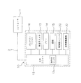
- the rear view of the underwater robot of FIG. The control block diagram of the underwater inspection system containing the underwater robot of FIG.
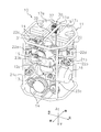
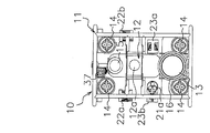
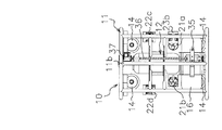
- the whole perspective view which shows the structure of the inspection camera mounted in the underwater robot of FIG. is an exploded perspective view of the inspection camera in FIG. 4.
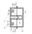
- FIG. 7 is a cross-sectional view taken along line AA in FIG. 6.
- the perspective view which shows the structure of the front case which comprises the inspection camera of FIG. The perspective view which shows the structure of the case which comprises the camera for an inspection of FIG.
- an inspection camera 13 (described later) provided in the underwater robot 10 corresponds to the imaging device of the present disclosure.
- the direction in which the operation camera 12a and the inspection camera 13 described later capture an image is defined as the front. That is, the direction (first direction) toward the subject along the optical axis of the inspection camera 13 or the like is set as the front, and the opposite is set as the back.
- a virtual axis that is parallel to the optical axis of the inspection camera 13 and extends in the front-rear direction is defined as a front-rear axis (first axis).
- a virtual axis that is orthogonal to the vertical axis and the front-rear axis is a left-right axis (third axis).
- the ascent / submarine is up / down
- the forward / reverse is forward / backward
- the left ( Alternatively, left turn / counterclockwise) / right turn (or right turn / clockwise) corresponds to the left / right direction.
- the direction of rotation about the front-rear axis is the roll direction
- the direction of rotation about the left-right axis is the pitch direction
- the direction of rotation about the vertical axis is the yaw direction.
- the underwater robot 10 of the present disclosure has the following configuration in view of such a problem.
- the underwater robot 10 shoots a wall surface or the like to be inspected while underwater in order to inspect a crack or the like generated on the wall surface of the dam.
- the underwater robot 10 includes a bumper 11, a body unit 12, an inspection camera 13, a sonar 14, a lighting 15, a battery unit 16, fixed buoyancy members 17a and 17b, A propulsion unit 20 and a posture adjustment mechanism 30 are provided.
- the underwater robot 10 is wired to the controller 1 via the cable 2, and operates according to the operation content input from the operator on the ground via the controller 1. ⁇
- the posture is controlled.
- the controller 1 includes, for example, a monitor that displays various information transmitted from the underwater robot 10, an input unit for operating the underwater robot 10, and the like.
- the controller 1 controls the propulsion unit 20 including a plurality of thrusters so as to maintain a constant position and posture relative to an inspection object (object) such as a dam wall. Controls the shooting operation of the camera 13 and the like.
- a notebook personal computer including a keyboard, a mouse, and a monitor can be used as the controller 1. Or as the controller 1, you may utilize the controller of the proportional system used by the control etc. of radio control equipment.
- the information transmitted from the underwater robot 10 to the controller 1 includes, for example, images taken by the underwater robot 10, values obtained from various sensors mounted on the underwater robot 10, and the propulsion unit 20. There are status values for each thruster included.
- the controller 1 may include a recording device for recording information transmitted from the underwater robot 10. Further, the controller 1 may include an image processing unit that performs image processing for sharpening an underwater image captured by the underwater robot 10.
- the cable 2 connecting the underwater robot 10 and the controller 1 is configured to include a signal line and a mooring line.
- the signal line enables communication between the underwater robot 10 and the controller 1 by an electric signal or an optical signal.
- the mooring line moores the underwater robot 10 and the controller 1.
- the mooring wire is formed of at least one of a metal and a resin, but the material is not limited to these.
- the signal line and the mooring line are integrally formed.
- a so-called cab having a structure in which a mooring wire is hollow and a signal wire is passed through the hollow portion, a signal wire and a mooring wire are twisted to form a twisted wire, and a wire or reinforcing material is provided in a protective tube.
- a tire cable or the like can be used. Thereby, the risk that a plurality of wires are tangled in water is reduced, and the cable can be easily routed.
- the structure which does not include a mooring line may be sufficient as the structure which a signal line serves as a mooring line.
- a winder (not shown) for winding the cable 2 may be provided between the underwater robot 10 and the controller 1.
- the underwater robot 10 and the winder may be connected by a mooring line, and the winder and the controller 1 may be connected only by a communication line.
- a winder what winds the cable 2 around a winding core and can be accommodated, and what is called a winch, a reel, and line winding can be utilized.
- the underwater robot 10 includes the bumper 11, the main unit 12, the inspection camera 13, the sonar 14, the illumination 15, the battery unit 16, the fixed buoyancy members 17a and 17b, the propulsion unit 20, and the attitude adjustment mechanism 30. Provided (see FIG. 1 and FIGS. 2A to 2E).
- the bumper 11 has two octagonal pipe-shaped members that constitute an upper surface and a lower surface, and rises from the four corners of these octagonal members along the vertical direction (second axial direction).
- the four pipe-shaped members provided are combined and fixed using bolts or the like.
- the body unit 12, the inspection camera 13, the sonar 14, the illumination 15, the battery unit 16, and the like are fixed to the bumper 11.
- the bumper 11 has a center frame 11a disposed along the front-rear direction (first axial direction) and a center frame 11b disposed along the vertical direction (second axial direction). is doing.
- the center frame 11a is disposed along the front-rear direction (first axial direction) at the central portion in the left-right direction (third axial direction) on the upper surface of the underwater robot 10. .
- the center frame 11a is used as a guide shaft for guiding the moving direction of the movable weight unit 31 of the posture adjusting mechanism 30 described later.
- the center frame 11b is disposed along the vertical direction (second axis direction) at the center portion in the left-right direction (third axis direction) on the back surface of the underwater robot 10. .
- the center frame 11b is used as a guide shaft for guiding the moving direction of the movable buoyancy material unit 35 of the posture adjusting mechanism 30 described later.
- the main unit 12 is a transparent cylindrical container in which an operation camera 12a is installed.
- the main unit 12 forms a waterproof structure in which water does not enter inside by sealing the contents such as the operation camera 12a with lids provided at both ends thereof.
- the main unit 12 is fixed to the substantially central portion of the bumper 11 so that the axis of the cylindrical container is arranged along the vertical direction (second axial direction).
- the operation camera 12a is an imaging device that captures a moving image or a still image when the underwater robot 10 is operated underwater. 1 and 2C, the operation camera 12a is fixed to the bumper 11 so that the optical axis of the camera is arranged along the front-rear direction (first axis direction) of the underwater robot 10. ing.
- the operation camera 12a is installed in a direction in which the forward direction of the underwater robot 10 is a shooting area.
- the operation camera 12 a captures a moving image or a still image from a transparent window portion formed in a cylindrical container constituting the main unit 12.
- the inspection camera 13 is provided as a configuration corresponding to the imaging device of the present disclosure.
- the inspection camera 13 is an imaging device for photographing a wall surface of a dam to be inspected, and can capture a high-resolution moving image or still image as compared with the operation camera 12a.
- the inspection camera 13 has the optical axis of the camera arranged along the front-rear direction (first axis direction) of the underwater robot 10 as in the case of the operation camera. As shown in the figure, it is fixed to the lower part of the bumper 11.
- the inspection camera 13 is installed in a direction in which the forward direction of the underwater robot 10 is the imaging region.
- the inspection camera 13 of the present embodiment includes a case (housing part, second housing) 41, a transparent plate (housing part, front panel) 42, and a front case (housing part, first housing). 1 housing) 43. Further, as shown in FIG. 5, the inspection camera 13 includes an imaging unit (camera) 13a and four laser irradiation units 13ba to 13bd in a sealed space formed by combining a case 41 and a front case 43. And a spring (elastic member) 44.
- the case 41 is a cylindrical member that forms a housing part opposite to the subject side (first direction) of the inspection camera 13, and includes the imaging unit 13a and the four laser irradiation units 13ba to 13bd. .
- the case 41 is formed as a metal (aluminum) housing, similarly to the front case 43 described later, and forms a sealed space in combination with the front case 43.
- the case 41 has a cylindrical portion 41a into which the rear end portion of the imaging portion 13a is inserted.
- the end surface 41aa of the cylindrical portion 41a holds a part of the spring 44 between the step portion 43aa formed at the end portion of the holding portion 43a on the front case 43 side described later.
- a notch 41ab for leading out the wiring 13aa connected to the imaging unit 13a is formed in a part of the circumference at the end of the cylindrical portion 41a.
- the transparent plate 42 is attached so as to cover the front surface of the front case 43 on the subject side, and is formed of a transparent resin.
- the transparent plate 42 is attached to the front surface of the front case 43 so as to form a waterproof structure that does not allow water to enter the inspection camera 13. Further, as shown in FIG. 7, the subject-side end surface of the imaging unit 13a is in contact with the inner surface of the transparent plate.
- the transparent plate 42 may be formed of a material that transmits light so that the imaging by the inspection camera 13 and the laser irradiation by the laser irradiation units 13ba to 13bd can be performed.
- the transparent plate 42 may be formed of glass, for example.
- the front case 43 is a member that constitutes the casing of the inspection camera 13 together with the case 41, and is formed as a metal (aluminum) casing. For this reason, when pressure (water pressure) is applied to the front case 43 from the outside, the front case 43 is elastically deformed inward.
- the front case 43 holds the imaging unit 13a in the holding unit 43a and the four laser irradiation units 13ba to 13bd in the holding unit 43b.
- the holding portion 43a is a cylindrical through hole formed in the central portion of the circular front surface of the front case 43, and the columnar imaging portion 13a is inserted as shown in FIG. It is held in the state.
- a stepped portion 43aa for holding a part of the spring 44 is formed on the end surface of the holding portion 43a.
- the stepped portion 43aa is an annular recess formed on the inner diameter side of the end surface of the cylindrical holding portion 43a, and the spring in a state where the end portion of the conical spring 44 is fitted. 44 is held.
- the holding portion 43b is a cylindrical through-hole arranged at intervals of 90 degrees on the circumference around the holding portion 43a. 13ba to 13bd are respectively inserted.
- the imaging unit 13a is a camera that captures an image for inspection such as a wall surface of a dam. As shown in FIGS. 6 and 7, the imaging unit 13a has an inside of a holding unit 43a formed at the center of the circular front surface of the front case 43. Is held in the inserted state.
- the imaging unit 13a is covered with a transparent plate 42 on the subject side in the optical axis X direction. Thereby, it is possible to perform photographing in the subject direction while preventing the transparent plate 42 from entering water into the inspection camera 13.
- the imaging unit 13a is inserted on the inner peripheral surface side of the cylindrical holding unit 43a, and the subject-side end surface (first end-side surface) is a transparent plate. 42 is held in contact with 42.
- the imaging unit 13 a is held by a spring 44 at the end (second end) opposite to the end surface in contact with the transparent plate 42. Thereby, the imaging unit 13a is always held in a state where the end surface on the subject side is pressed against the transparent plate.
- the four laser irradiation units 13ba to 13bd irradiate the laser in parallel with the optical axis X of the imaging unit 13a toward the subject side in the optical axis X direction. That is, the optical axes of the four laser irradiation units 13ba to 13bd and the optical axis X of the imaging unit 13a are parallel to each other. Further, as shown in FIG. 6, the laser irradiation units 13ba to 13bd are arranged at intervals of 90 degrees on the circumference centering on the imaging unit 13a.
- the four laser irradiation units 13ba to 13bd are arranged on two axes on a plane orthogonal to the optical axis X of the imaging unit 13a along a circumference centered on the optical axis X of the imaging unit 13a. Has been.
- the laser beams irradiated from the four laser irradiation units 13ba to 13bd are irradiated to the wall surface of the dam along a direction parallel to the optical axis X of the imaging unit 13a, thereby forming four spots P1 to P4.
- the interval between the spots serves as a reference when measuring the size of the scratch on the wall surface.
- the spring 44 is a conical coil spring that presses the imaging unit 13 a from the side opposite to the subject (object) toward the subject, and is provided in a sealed space formed by the front case 43 and the case 41. ing. As shown in FIGS. 7 and 8, the spring 44 is provided so as to be locked to a connection portion between the case 41 and the front case 43. That is, the spring 44 is disposed in a gap formed between the stepped portion 43aa formed on the end surface of the cylindrical holding portion 43a of the front case 43 and the end surface 41aa of the cylindrical portion 41a of the case 41.
- the end of the spring 44 having the larger conical radius is held by a step 43 aa formed on the end surface of the holding part 43 a of the front case 43.
- the spring 44 provides the elastic force F1 (refer FIG. 11) which presses the rear-end part of the imaging part 13a forward.
- the imaging unit 13a receives the elastic force of the spring 44 from the rear end side.
- the imaging unit 13a can maintain the maximum angle of view. Furthermore, since the transparent plate 42 to which pressure (water pressure) is applied from the outside is supported from the inside of the case 41 by the cylindrical portion 41a and the holding portion 43a constituting the case 41, the amount of deformation can be minimized. Can do. As a result, it is possible to prevent the imaging unit 13a from being separated from the transparent plate 42 and narrowing the angle of view, and to suppress the deformation of the transparent plate 42 that has been subjected to water pressure.
- the sonar 14 has a sound wave transmitter and a sound wave detector in order to detect a distance from an inspection object such as a wall surface of a dam.
- the sonar 14 is arranged at the four corners on the front side of the bumper 11 in front view as shown in FIGS. 1 and 2C in order to be able to detect the distance from the object in front of the underwater robot 10. Yes.
- the object to be inspected is a flat surface such as a dam wall, etc., diagonally such as upper left and lower right, upper right and lower left on the front surface of the bumper 11, as in this embodiment. It is preferable to provide in two places respectively. This makes it possible to perform wall surface photography while maintaining a stable relative posture with the inspection object such as the dam wall surface of the dam, so that an image suitable for image processing is obtained as an image of the inspection object. Data can be easily acquired.
- the illumination 15 irradiates the inspection object with light for ensuring illuminance that can be photographed by the inspection camera 13. Moreover, the illumination 15 is being fixed to the upper center of the front surface in the bumper 11, as shown to FIG. 1 and FIG. 2C. Thereby, the front of the operation camera 12a and the inspection camera 13 in the optical axis direction can be maintained so that the illuminance can be taken.
- the illumination 15 when the illumination 15 is one, it is preferable to utilize the illumination which can illuminate a test object uniformly. Further, when a plurality of illuminations 15 are provided, positions where each illumination is attached so that the illuminance within the screen or the range used for the image processing is uniform so that the image processing is not affected by the overlapping of both illuminations. It is preferable to adjust the direction.
- the illumination 15 may be configured such that the illuminance and the like are controlled by the controller 1.
- the battery unit 16 As shown in FIG. 3, the battery unit 16 is connected to the main unit 12 (operation camera 12 a), and through the electric circuit in the main unit 12, the inspection camera 13, the sonar 14, the illumination 15, and the propulsion. Electric power is supplied to the container unit 20 and the posture adjustment mechanism 30. As shown in FIGS. 1 and 2C, the battery unit 16 is fixed to the lower portion of the bumper 11, in particular, to the lower end surface using a binding band or a screw.
- the gravity center position of the underwater robot 10 can be set to a low position, the underwater posture of the underwater robot 10 can be stabilized.
- the battery unit 16 is detachably connected to the main body unit 12 and the illumination 15 that are sealed containers using a waterproof connector or the like.
- the fixed buoyancy members 17a and 17b are buoyancy members provided for imparting buoyancy to the underwater robot 10, and are fixedly disposed at positions closer to the rear on the upper surface of the bumper 11, as shown in FIGS. Has been. Further, in order to avoid the fixed buoyancy members 17a and 17b from becoming a barrier to the propulsive force of the upper and lower thrusters 22c and 22d provided below the upper and lower thrusters 22c and 22d in a plan view, as shown in FIG. 2A. It has a shape in which the overlapping part is cut out.
- the propulsion unit 20 is a mechanism that generates a propulsive force when the underwater robot 10 moves in water, and is configured by combining a screw (also called a propeller) and a motor (electric motor) that rotates the screw. It is comprised by the thruster.
- the propulsion unit 20 is controlled in the front / rear, left / right, and up / down directions (first to third axis directions) by controlling the rotational speed of the motor of each thruster by instruction input from the controller 1 or automatic attitude control. Propulsion is controlled.
- the propulsion unit 20 includes front and rear thrusters (first thrusters) 21a and 21b, upper and lower thrusters (second thrusters) 22a to 22d, and left and right thrusters (first thrusters). 3 propulsion units) 23a and 23b.
- the front and rear thrusters 21a and 21b, the upper and lower thrusters 22a to 22d, and the left and right thrusters 23a and 23b are each translated in the direction of each axis of the underwater robot 10 and each axis in three orthogonal axes (first to third axes). It is possible to rotate around.
- the front and rear thrusters 21a and 21b, the upper and lower thrusters 22a to 22d, and the left and right thrusters 23a and 23b are fixed to the bumper 11, respectively.
- the front and rear thrusters 21a and 21b, the upper and lower thrusters 22a to 22d, and the left and right thrusters 23a and 23b are controlled independently.
- the direction of the thruster refers to the direction parallel to the rotation axis of the screw included in each thruster, that is, the direction of the thrust generated by each thruster.
- first thrusters the two front and rear thrusters (first thrusters) 21a and 21b generate a propulsive force in water in the front and rear direction (first axial direction). It is fixed at the right front and rear left positions.
- the front and rear thrusters 21a and 21b are fixed to the bumper 11 at a position slightly below the center in the vertical direction (second axis direction).
- the front and rear thrusters 21a and 21b are arranged so that the rotation axes of the thrusters are parallel to each other in the front and rear direction (first axis direction).
- the front and rear thrusters 21a and 21b indicate the center of gravity position g1 (see FIG. 2A) in the upright posture of the underwater robot 10 in plan view. It is arranged at a symmetrical position as the center. Accordingly, by changing the output of the propulsive force of each of the front and rear thrusters 21a and 21b, the underwater robot 10 is moved in the front-rear direction in a stable state, or tilted with respect to the first axis along the front-rear direction. can do. That is, the underwater robot 10 can be moved in the front-rear direction or rotated in the yaw direction.
- the four vertical thrusters (second propulsion units) 22a to 22d generate a propulsive force in water in the vertical direction (second axial direction), as shown in FIGS. 1 and 2B to 2E in plan view. Near the four corners of the bumper 11.
- the upper and lower thrusters 22a to 22d are provided at positions slightly above the center of the bumper 11 in the vertical direction. Further, the upper and lower thrusters 22a to 22d require a large driving force when the underwater robot 10 dives. For this reason, as the upper and lower thrusters 22a to 22d, thrusters capable of generating a larger propulsive force than other thrusters (front and rear thrusters 21a and 21b and left and right thrusters 23a and 23b) are used.
- the size of the blades of the screws of the upper and lower thrusters 22a to 22d, the output of the motor, the rotational speed, etc. may be adjusted so as to be larger than those of other thrusters.
- the four vertical thrusters 22a to 22d are fixed to the bumper 11 so as to face the vertical direction (second axis direction). That is, the upper and lower thrusters 22a to 22d are arranged so that the rotation axes of the thrusters are parallel to each other in the vertical direction.
- the upper and lower thrusters 22a to 22d are arranged in the vicinity of the four corners of a rectangle centering on the gravity center position g1 of the underwater robot 10 in plan view on the same plane orthogonal to the respective rotation axes. Accordingly, by changing the propulsive force output of the four vertical thrusters 22a to 22d, the underwater robot 10 can be moved in the vertical direction or tilted with respect to the vertical direction (second axis direction). . That is, the underwater robot 10 can be moved in the vertical direction or rotated (forward tilt / back tilt) in the roll direction and the pitch direction.
- the battery unit 16 that is heavier than other components is disposed on the lower end surface of the bumper 11. For this reason, when the underwater robot 10 is moved up and down in the water, the posture can be stabilized.
- the two left and right thrusters (third propellers) 23a and 23b generate a propulsive force in water in the left and right direction (third axial direction). It is fixed at the front left and back right positions.
- the left and right thrusters 23a and 23b are fixed to the bumper 11 at a position slightly lower than the center in the vertical direction (second axis direction), that is, at a height position substantially the same as the front and rear thrusters 21a and 21b.
- the left and right thrusters 23a and 23b are arranged so that the rotation axes of the thrusters are parallel to each other in the left and right direction (third axis direction).
- the left and right thrusters 23a and 23b are positioned in the center of gravity g1 of the underwater robot 10 in an upright position in plan view (see FIG. 2A). Are arranged at symmetrical positions with respect to the center.
- the underwater robot 10 can be moved in the left-right direction or tilted with respect to the third axis along the left-right direction. can do. That is, the underwater robot 10 can be moved in the left-right direction or rotated in the yaw direction.
- the posture adjustment mechanism 30 is a mechanism for rotating the underwater robot 10 to a forward tilt posture by rotating about the third axis along the left-right direction, and moves the center of gravity position and the floating position of the underwater robot 10. It is provided to make it.
- the posture adjusting mechanism 30 includes a movable weight unit 31, a first feed screw 32, a movable buoyancy material unit 35, a second feed screw 36, and a gear. And a box 37. (Movable weight unit 31)
- the movable weight unit 31 moves in the front-rear direction along with the rotation of the first feed screw 32 arranged along the front-rear direction. Move back and forth.
- the position close to the gear box 37 is set as the initial position of the movable weight unit 31.
- the movable weight unit 31 is moved to a position separated from the gear box 37 as shown in FIG. That is, when the underwater robot 10 moves underwater in an upright posture (see FIG. 1 and the like), the movable weight unit 31 is in the initial position of the rear end in the front-rear direction.
- the movable weight unit 31 moves to the position of the front end in the front-rear direction in conjunction with the movement of the movable buoyancy material unit 35 in the vertical direction. Thereby, the gravity center position of the underwater robot 10 can be moved to the front position in the front-rear direction.
- the first feed screw 32 is disposed along the front-rear direction (first axial direction) as shown in FIGS.
- the first feed screw 32 has a feed groove and a stop groove formed on the outer peripheral surface, and moves the movable weight unit 31 in the front-rear direction by rotating.
- the first feed screw 32 and the second feed screw 36 described later have substantially the same configuration although the pitch of the feed grooves is different.
- the feed groove is formed as one groove that is continuously formed along the front-rear direction obliquely to the axial direction of the cylindrical first feed screw 32.
- the movable weight unit 31 can move in the front-rear direction by rotating the first feed screw 32 in a state where a part of the movable weight unit 31 is locked in the feed groove.
- the stop groove is an annular groove formed along a plane perpendicular to the axial direction of the cylindrical first feed screw 32, and is formed at both ends of the feed groove.
- the movable buoyancy material unit 35 In order to move the buoyancy position of the underwater robot 10 in the vertical direction (second axis direction), the movable buoyancy material unit 35 moves up and down as the second feed screw 36 arranged along the vertical direction rotates. Move back and forth in the direction. In the underwater robot 10 of the present embodiment, the position close to the gear box 37 is set as the initial position of the movable buoyancy material unit 35, similarly to the movable weight unit 31. When the underwater robot 10 is shifted to the forward tilt posture, the movable buoyancy material unit 35 is moved to a position away from the gear box 37.
- the movable buoyancy material unit 35 when the underwater robot 10 moves underwater in an upright posture (see FIG. 1 and the like), the movable buoyancy material unit 35 is in the initial position of the upper end in the vertical direction. When the underwater robot 10 shifts to the forward tilt posture, the movable buoyancy material unit 35 moves to the lower end position in the vertical direction in conjunction with the movement of the movable weight unit 31 in the front-rear direction.
- the floating position of the underwater robot 10 can be moved to a downward position in the vertical direction.
- the second feed screw 36 is disposed along the vertical direction (second axial direction).
- the second feed screw 36 has a feed groove and a stop groove formed on the outer peripheral surface thereof, and moves the movable buoyancy material unit 35 in the vertical direction by rotating.
- the feed groove is formed as a single groove that is continuously formed along the front-rear direction, obliquely with respect to the axial direction of the cylindrical second feed screw 36.
- the movable buoyancy material unit 35 can move in the vertical direction by rotating the second feed screw 36 in a state where a part of the movable buoyancy material unit 35 is locked in the feed groove.
- the moving distance of the movable buoyancy material unit 35 in the vertical direction is longer than the moving distance of the movable weight unit 31 in the front-rear direction
- the pitch of the feed groove of the second feed screw 36 is the first feed. It is set to be larger than the pitch of the feed groove of the screw 32.
- the stop groove is an annular groove formed along a plane perpendicular to the axial direction of the cylindrical second feed screw 36, and is formed at both ends of the feed groove.
- the gear box (drive mechanism) 37 is provided at the rear end of the upper surface of the bumper 11 in order to drive the movable weight unit 31 and the movable buoyancy material unit 35 in the front-rear direction and the vertical direction, respectively.
- the gear box 37 is configured by combining a single drive source (motor) (not shown) provided therein and a plurality of gears.
- a single drive source (motor) in the gear box 37 has a plurality of gears, a rear end of the first feed screw 32 disposed along the front-rear direction, and a second feed disposed along the vertical direction.
- the upper ends of the screws 36 are connected to each other.
- the gear box 37 applies a rotational driving force to the first feed screw 32 and the second feed screw 36, respectively.
- the rotational driving force applied from the gear box 37 is such that when the movable weight unit 31 moves in the forward direction, the movable buoyancy material unit 35 moves downward in conjunction with this. It is transmitted to the first feed screw 32 and the second feed screw 36.
- the direction which rotates the 1st feed screw 32 and the 2nd feed screw 36 should just be set according to the direction in which each feed groove was formed. For example, when viewed from the gear box 37, the first feed screw 32 and the second feed screw 36 may be rotated in the same direction or may be rotated in opposite directions.
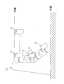
- the underwater robot 10 of the present embodiment for example, the wall surfaces 51a and 51b of the dam body 50 shown in FIG. Specifically, as shown in FIG. 12, the underwater robot 10 is submerged at a position L1 near the water surface based on the operation input from the controller 1, and the wall surface of the dam body 50 to be inspected. It approaches 51a.
- the underwater robot 10 approaches the wall surface 51a while maintaining the upright posture by controlling the propulsive force in the three-axis directions by the thrusters of the propulsion unit 20.
- the underwater robot 10 moves forward using the propulsive force of the front and rear thrusters 21a and 21b while maintaining the upright posture using the propulsive force of the vertical thrusters 22a to 22d and the left and right thrusters 23a and 23b.
- the controller 1 moves in the target direction while confirming the video acquired by the operation camera 12a on the monitor screen.
- the underwater robot 10 moves to a position L2 that is a distance ds between the front surface (for example, the inspection camera 13) and the wall surface 51a. At this position L2, the underwater robot 10 activates the inspection camera 13 and starts photographing the wall surface 51a. Next, the underwater robot 10 moves while repeating the horizontal movement and the descent while maintaining the distance ds to the wall surface 51a while maintaining the upright posture.
- the vertical thrusters 22a to 22d are maintained while using the propulsive force of the front and rear thrusters 21a and 21b, the vertical thrusters 22a to 22d and the left and right thrusters 23a and 23b. Move up and down using the propulsive force of.
- the underwater robot 10 moves in the left-right direction, the underwater robot 10 maintains the upright posture by using the propulsive force of the front and rear thrusters 21a, 21b, the upper and lower thrusters 22a-22d and the left and right thrusters 23a, 23b, and the left and right thrusters 23a, 23b. Use the thrust to move left and right.
- the inspection camera 13 can acquire an image for inspection of the wall surface 51a arranged along the substantially vertical direction.
- the image acquired by the inspection camera 13 may be a moving image or a still image.
- the underwater robot 10 moves from the wall surface 51a to be inspected to a position L2 at a distance ds. Thereafter, the underwater robot 10 starts imaging at a desired timing and continuously performs imaging until the position L3 at the boundary between the wall surface 51a and the wall surface 51b is reached.
- the underwater robot 10 moves from the wall surface 51a to be inspected to a position L2 at a distance ds. Thereafter, the underwater robot 10 moves while confirming the state of the wall surface 51a by the operation camera 12a, and takes a still image at a desired timing at a position where an abnormality such as a scratch is seen. Next, when the underwater robot 10 reaches the position L3 of the boundary portion between the wall surface 51a and the wall surface 51b, the underwater robot 10 takes a forward tilt posture in accordance with the angle of the inclined wall surface 51b to be inspected next. Can be switched.
- the movable weight unit 31 and the movable buoyancy material unit 35 are moved in a predetermined direction by the posture adjusting mechanism 30 described above at a position L3 shown in FIG.
- the position of the center of gravity moves and the buoyancy position moves, whereby the underwater robot 10 can be tilted (tilted forward) in the pitch direction (position L4).
- the forward tilt angle at the position L4 that is, the moving distance between the movable weight unit 31 and the movable buoyancy material unit 35 is set to be parallel to the angle of the wall surface 51b to be inspected.
- design data such as a dam may be input in advance.
- the inclination angle of the wall surface 51b may be obtained by measuring the distance to the wall surface 51b in the upright posture using the operation camera 12a, the inspection camera 13, the sonar 14, and the like.
- the underwater robot 10 moves while repeating the movement in the left-right direction and the movement in the diagonally downward direction while maintaining the distance ds to the wall surface 51b while maintaining the forward tilt posture.
- the vertical thruster 22a is maintained while maintaining a forward tilting posture using the propulsive force of the front and rear thrusters 21a and 21b, the vertical thrusters 22a to 22d and the left and right thrusters 23a and 23b. Move diagonally downward using the propulsive force of ⁇ 22d.
- the left and right thrusters 23a, 23b are maintained in a forward tilted posture using the propulsive force of the front and rear thrusters 21a, 21b, the upper and lower thrusters 22a-22d and the left and right thrusters 23a, 23b. Move left and right using the propulsive force of
- the inspection camera 13 that performs imaging of the wall surface of the dam in water has been described as an example of the configuration corresponding to the imaging device of the present disclosure.
- the present disclosure is not limited to this.
- the place where the imaging device performs shooting is not limited to underwater, but may be any environment where pressure is applied from the outside, such as an environment where there is a difference from the internal pressure of the casing, such as in space. .
- the same effect as described above can be obtained.
- the example using the imaging part (camera) 13a was mentioned and demonstrated as an imaging part.
- the present disclosure is not limited to this.
- the structure of the present disclosure may be adopted in the configuration of an illumination device such as an LED mounted on the imaging device.
- the inspection camera 13 including the four laser irradiation units 13ba to 13bd is described as an example.
- the present disclosure is not limited to this.
- the number of laser irradiation units mounted on the inspection camera 13 may be three or two. Even in this case, if the interval of the position of the laser irradiation unit is stored in advance, by calculating how many pixels the interval of the spot in the image corresponds to, using the actual interval of the laser irradiation unit, It is possible to measure the size of an inspection object such as a flaw on a dam wall.
- the arrangement of the laser irradiation units in the inspection camera may be any arrangement as long as the interval between the positions of the laser beams emitted from the respective laser irradiation units is set.
- F In the above-described embodiment, an example in which the imaging unit 13a and the four laser irradiation units 13ba to 13bd are attached to the common front case 43 has been described. However, the present disclosure is not limited to this.
- the imaging unit 13a and the four laser irradiation units 13ba to 13bd may be attached to different members.
- the case 41 and the front case 43 that form the housing unit that includes the imaging unit (camera) 13a are described as examples that are both formed as an aluminum housing.
- the present invention is not limited to this.
- the case 41 and the front case 43 may be formed using a metal other than aluminum or a material other than metal.
- the case 41 and the front case 43 may be formed of different materials.
- the wall surface of the dam was mentioned as an example and demonstrated as an inspection target object using the underwater robot 10 which concerns on this indication.
- the present disclosure is not limited to this.
- the inspection system of the present disclosure can be applied to various inspections and the like in an environment in which external pressure is applied to the casing of the inspection camera.
- the inspection apparatus which inspects the wall surface of a dam in water was mentioned as an example, and was demonstrated.
- the present disclosure is not limited to this.
- the imaging device of the present disclosure may be realized as an imaging device that performs imaging of an object in an environment in which an external pressure such as water pressure is applied without performing an inspection.
- the imaging device reduces the influence of pressure applied from the outside and suppresses deterioration in the quality of the captured image even when shooting is performed in an environment where pressure is applied from the outside. Therefore, the present invention is widely applicable to imaging devices used in an environment where an external pressure such as water is applied.
Landscapes
- General Health & Medical Sciences (AREA)
- General Physics & Mathematics (AREA)
- Life Sciences & Earth Sciences (AREA)
- Chemical & Material Sciences (AREA)
- Analytical Chemistry (AREA)
- Biochemistry (AREA)
- Health & Medical Sciences (AREA)
- Studio Devices (AREA)
- Physics & Mathematics (AREA)
- Pathology (AREA)
- Immunology (AREA)
- Investigating Materials By The Use Of Optical Means Adapted For Particular Applications (AREA)
- Structure And Mechanism Of Cameras (AREA)
- Accessories Of Cameras (AREA)
- Monitoring And Testing Of Nuclear Reactors (AREA)
Abstract
水中用ロボット(10)は、フロントケース(43)、撮像部(13a)、バネ(44)を備えている。フロントケース(43)は、検査時に被検査物に対向配置され可視光を透過する透明板(42)を有する。撮像部(13a)は、検査時に被検査物側に配置される第1端が透明板(42)の内側の面に当接するように配置され、透明板(42)を介して被検査物の検査を行う。バネ(44)は、撮像部(13a)を透明板(42)に向かって押圧する押圧力を付与する。
Description
本開示は、例えば、水中において撮影を行う撮像装置に関する。
近年、ダム等の壁面を検査するために、水中で移動しながら壁面の撮影を行う撮像装置が用いられている。
例えば、特許文献1には、カメラと光源とを用いて壁面等の検査を行う検査装置について開示されている。また、特許文献2には、防水カメラの耐水構造について開示されている。
例えば、特許文献1には、カメラと光源とを用いて壁面等の検査を行う検査装置について開示されている。また、特許文献2には、防水カメラの耐水構造について開示されている。
しかしながら、上記従来の撮像装置では、以下に示すような問題点を有している。
すなわち、上記公報に開示された撮像装置では、例えば、水深が深いダム等の検査において使用されると、水圧の影響を受けてカメラや光源を収納した筐体部が変形してしまい、撮像した画像の画質が低下してしまうおそれがある。
特に、筐体部内に設けられたカメラは、筐体部の変形の影響を受けないように筐体部の内面から離間して配置すると、画角が狭まってしまうことから、できるだけ筐体部の内面に近接して配置することが望ましい。
すなわち、上記公報に開示された撮像装置では、例えば、水深が深いダム等の検査において使用されると、水圧の影響を受けてカメラや光源を収納した筐体部が変形してしまい、撮像した画像の画質が低下してしまうおそれがある。
特に、筐体部内に設けられたカメラは、筐体部の変形の影響を受けないように筐体部の内面から離間して配置すると、画角が狭まってしまうことから、できるだけ筐体部の内面に近接して配置することが望ましい。
一方で、カメラが筐体部の内面に近接配置された場合には、水圧による筐体部の変形の影響を受けやすくなり、カメラのレンズの変形等の問題が生じるおそれがある。
本開示の課題は、外部から圧力が付与される環境下において撮像を実施する場合でも、外部から付与される圧力による影響を低減させて、撮影された画像の画質が低下することを抑制することが可能な撮像装置を提供することにある。
本開示の課題は、外部から圧力が付与される環境下において撮像を実施する場合でも、外部から付与される圧力による影響を低減させて、撮影された画像の画質が低下することを抑制することが可能な撮像装置を提供することにある。
本開示に係る撮像装置は、対象物の撮影を行う撮像装置であって、筐体部と、撮像部と、弾性部材と、を備えている。筐体部は、撮影時に対象物に対向配置され可視光を透過する前面パネルを有する。撮像部は、撮影時に対象物側に配置される第1端が前面パネルの内面側に当接するように筐体部の内部に配置され、前面パネルを介して対象物の撮影を行う。弾性部材は、撮像部を前面パネルに向かって押圧する押圧力を付与する。
本開示に係る撮像装置によれば、外部から圧力が付与される環境下において撮影を実施する場合でも、外部から付与される圧力による影響を低減させて、撮影された画像の画質が低下することを抑制することができる。
以下、適宜図面を参照しながら、実施の形態を詳細に説明する。ただし、必要以上に詳細な説明は省略する場合がある。例えば、既によく知られた事項の詳細説明や実質的に同一の構成に対する重複説明を省略する場合がある。これは、以下の説明が不必要に冗長になるのを避け、当業者の理解を容易にするためである。
なお、出願人は、当業者が本開示を十分に理解するために添付図面および以下の説明を提供するのであって、これらによって特許請求の範囲に記載の主題を限定することを意図するものではない。
なお、出願人は、当業者が本開示を十分に理解するために添付図面および以下の説明を提供するのであって、これらによって特許請求の範囲に記載の主題を限定することを意図するものではない。
(実施形態1)
本開示の一実施形態に係る水中用ロボット(ROV:Remotely Operated Vehicle)(検査装置)10について、図1~図12を用いて説明すれば以下の通りである。
なお、本実施形態では、以下の説明において、上下・前後・左右の各方向を図1に示すように定義する。
本開示の一実施形態に係る水中用ロボット(ROV:Remotely Operated Vehicle)(検査装置)10について、図1~図12を用いて説明すれば以下の通りである。
なお、本実施形態では、以下の説明において、上下・前後・左右の各方向を図1に示すように定義する。
すなわち、水中用ロボット10が水中において潜行している際の基本姿勢において、水面側を上、水底側を下と定義する。そして、円筒状の本体ユニット12の中心軸に沿って上下方向に伸びる仮想的な軸を上下軸(第2軸)とする。
なお、本実施形態では、水中用ロボット10が備えている後述する検査用カメラ13が、本開示の撮像装置に相当する。
なお、本実施形態では、水中用ロボット10が備えている後述する検査用カメラ13が、本開示の撮像装置に相当する。
この上下軸の方向に直交する平面において、後述する操作用カメラ12aおよび検査用カメラ13が撮影する方向を前と定義する。つまり、検査用カメラ13等の光軸に沿って被写体へ向かう方向(第1方向)を前とし、その反対を後とする。そして、検査用カメラ13の光軸と平行であって、前後方向に伸びる仮想的な軸を前後軸(第1軸)とする。
さらに、上下軸と前後軸とにそれぞれ直交する仮想的な軸を左右軸(第3軸)とする。
さらに、上下軸と前後軸とにそれぞれ直交する仮想的な軸を左右軸(第3軸)とする。
従って、操縦者が操作用カメラ12aによって撮影された画面をコントローラ1のモニタ等で見ながら操作する場合には、浮上/潜航が上/下方向、前進/後進が前/後方向、左進(あるいは左旋回/反時計回り)/右進(あるいは右旋回/時計回り)が左/右方向に対応する。
また、以下の説明では、前後軸を中心とする回転の方向をロール方向、左右軸を中心とする回転の方向をピッチ方向、上下軸を中心とする回転の方向をヨー方向とする。
また、以下の説明では、前後軸を中心とする回転の方向をロール方向、左右軸を中心とする回転の方向をピッチ方向、上下軸を中心とする回転の方向をヨー方向とする。
ここで、高速道路やダム等の社会インフラは、建設されて長い年月が経過したことによる老朽化が進んでいる。近年、これらの社会インフラにおける事故や災害等の発生を未然に防ぐために、点検・整備等が重要となっている。
例えば、ダムの点検は、水深の深い位置まで潜水して点検作業を行う必要があり、ダイバーによる点検作業ではリスクを伴うとともに高額な費用がかかってしまう。このため、人の代わりとして水中の様子を把握できるように、水中用ロボットが開発されている。しかしながら、従来の水中用ロボットは、ダムの壁面に対して相対的な位置・姿勢を任意の状態に制御したり、一定に保持したりすることが難しく、鮮明な画像を得ることが困難であった。本開示の水中用ロボット10は、このような課題に鑑みて、以下のような構成を備えたものである。
例えば、ダムの点検は、水深の深い位置まで潜水して点検作業を行う必要があり、ダイバーによる点検作業ではリスクを伴うとともに高額な費用がかかってしまう。このため、人の代わりとして水中の様子を把握できるように、水中用ロボットが開発されている。しかしながら、従来の水中用ロボットは、ダムの壁面に対して相対的な位置・姿勢を任意の状態に制御したり、一定に保持したりすることが難しく、鮮明な画像を得ることが困難であった。本開示の水中用ロボット10は、このような課題に鑑みて、以下のような構成を備えたものである。
水中用ロボット10は、例えば、ダムの壁面に生じた亀裂等の検査を実施するために、水中において潜行しながら検査対象となる壁面等の撮影を行う。そして、水中用ロボット10は、図1および図2A~図2Eに示すように、バンパー11、本体ユニット12、検査用カメラ13、ソナー14、照明15、バッテリユニット16、固定浮力材17a,17b、推進器ユニット20、姿勢調整機構30を備えている。
また、水中用ロボット10は、図3に示すように、ケーブル2を介して、コントローラ1に有線接続されており、地上の操作者からコントローラ1を介して入力された操作内容に応じて、動作・姿勢等が制御される。
コントローラ1は、例えば、水中用ロボット10から送信される各種情報を表示するモニタ、水中用ロボット10を操縦するための入力部等を有している。そして、コントローラ1は、ダムの壁面等の検査対象物(対象物)との相対的な位置および姿勢を一定に保持するように、複数のスラスタを含む推進器ユニット20を制御しながら、検査用カメラ13等の撮影動作を制御する。
コントローラ1は、例えば、水中用ロボット10から送信される各種情報を表示するモニタ、水中用ロボット10を操縦するための入力部等を有している。そして、コントローラ1は、ダムの壁面等の検査対象物(対象物)との相対的な位置および姿勢を一定に保持するように、複数のスラスタを含む推進器ユニット20を制御しながら、検査用カメラ13等の撮影動作を制御する。
ここで、コントローラ1としては、キーボード、マウス、およびモニタを含むノートパソコン等を利用することができる。あるいは、コントローラ1としては、ラジコン機器の操縦等で使用されるプロポーショナル方式のコントローラを利用してもよい。
なお、水中用ロボット10からコントローラ1へ送信される情報としては、例えば、水中用ロボット10において撮影された画像や、水中用ロボット10に搭載された各種センサから取得した値、推進器ユニット20に含まれる各スラスタの状態値等がある。
なお、水中用ロボット10からコントローラ1へ送信される情報としては、例えば、水中用ロボット10において撮影された画像や、水中用ロボット10に搭載された各種センサから取得した値、推進器ユニット20に含まれる各スラスタの状態値等がある。
また、コントローラ1は、水中用ロボット10から送信される情報を記録するための記録装置を備えていてもよい。さらに、コントローラ1は、水中用ロボット10において撮影された水中の画像を鮮明化する画像処理を行う画像処理部を備えていてもよい。
水中用ロボット10とコントローラ1との間を接続するケーブル2は、信号線と係留線とを含むように構成されている。
水中用ロボット10とコントローラ1との間を接続するケーブル2は、信号線と係留線とを含むように構成されている。
信号線は、電気信号あるいは光信号によって、水中用ロボット10とコントローラ1との間の通信を可能とする。係留線は、水中用ロボット10とコントローラ1とを係留する。
ここで、係留線は、少なくとも、金属および樹脂のいずれかの素材によって形成されているが、材質としてはこれらに限定されるものではない。
ここで、係留線は、少なくとも、金属および樹脂のいずれかの素材によって形成されているが、材質としてはこれらに限定されるものではない。
また、信号線と係留線とは、一体的に形成されていることが好ましい。例えば、係留線を中空としてその中空部に信号線を通したものや、信号線と係留線をねじり合わせて撚り線としたもの、線材や補強材を保護チューブ内に設けた構成とするいわゆるキャブタイヤケーブル等を用いることができる。
これにより、水中で複数の線同士が絡まってしまうリスクが低減され、ケーブルの取り回しが容易になる。
これにより、水中で複数の線同士が絡まってしまうリスクが低減され、ケーブルの取り回しが容易になる。
なお、信号線のみで係留に十分な強度が得られる場合には、信号線が係留線を兼ねる構成とし、係留線を含まない構成であってもよい。
また、水中用ロボット10とコントローラ1との間には、ケーブル2を巻き取るための巻き取り器(図示せず)が設けられていてもよい。
この場合には、水中用ロボット10と巻き取り器との間は係留線によって接続し、巻き取り器とコントローラ1との間は通信線のみで接続してもよい。なお、巻き取り器としては、巻き芯にケーブル2を巻き取って収納可能とするものであって、いわゆるウインチやリール、ライン巻きと呼ばれるものを利用することができる。
また、水中用ロボット10とコントローラ1との間には、ケーブル2を巻き取るための巻き取り器(図示せず)が設けられていてもよい。
この場合には、水中用ロボット10と巻き取り器との間は係留線によって接続し、巻き取り器とコントローラ1との間は通信線のみで接続してもよい。なお、巻き取り器としては、巻き芯にケーブル2を巻き取って収納可能とするものであって、いわゆるウインチやリール、ライン巻きと呼ばれるものを利用することができる。
<水中用ロボット10の構成>
水中用ロボット10は、上述したように、バンパー11、本体ユニット12、検査用カメラ13、ソナー14、照明15、バッテリユニット16、固定浮力材17a,17b、推進器ユニット20、姿勢調整機構30を備えている(図1および図2A~図2E参照)。
水中用ロボット10は、上述したように、バンパー11、本体ユニット12、検査用カメラ13、ソナー14、照明15、バッテリユニット16、固定浮力材17a,17b、推進器ユニット20、姿勢調整機構30を備えている(図1および図2A~図2E参照)。
(バンパー11)
バンパー11は、図1等に示すように、上面と下面を構成する2つの八角形のパイプ状部材と、これらの八角形の部材の4隅から上下方向(第2軸方向)に沿って立設された4本のパイプ状部材とを組み合わせた状態で、ボルト等を用いて固定して構成されている。そして、バンパー11には、上述した本体ユニット12、検査用カメラ13、ソナー14、照明15、バッテリユニット16等が固定される。また、バンパー11は、図1に示すように、前後方向(第1軸方向)に沿って配置されたセンターフレーム11a、上下方向(第2軸方向)に沿って配置されたセンターフレーム11bを有している。
バンパー11は、図1等に示すように、上面と下面を構成する2つの八角形のパイプ状部材と、これらの八角形の部材の4隅から上下方向(第2軸方向)に沿って立設された4本のパイプ状部材とを組み合わせた状態で、ボルト等を用いて固定して構成されている。そして、バンパー11には、上述した本体ユニット12、検査用カメラ13、ソナー14、照明15、バッテリユニット16等が固定される。また、バンパー11は、図1に示すように、前後方向(第1軸方向)に沿って配置されたセンターフレーム11a、上下方向(第2軸方向)に沿って配置されたセンターフレーム11bを有している。
センターフレーム11aは、図1および図2Aに示すように、水中用ロボット10の上面における左右方向(第3軸方向)の中央部分において、前後方向(第1軸方向)に沿って配置されている。そして、センターフレーム11aは、後述する姿勢調整機構30の可動おもりユニット31の移動方向を誘導するガイド軸として使用される。
センターフレーム11bは、図1および図2Eに示すように、水中用ロボット10の背面における左右方向(第3軸方向)の中央部分において、上下方向(第2軸方向)に沿って配置されている。そして、センターフレーム11bは、後述する姿勢調整機構30の可動浮力材ユニット35の移動方向を誘導するガイド軸として使用される。
センターフレーム11bは、図1および図2Eに示すように、水中用ロボット10の背面における左右方向(第3軸方向)の中央部分において、上下方向(第2軸方向)に沿って配置されている。そして、センターフレーム11bは、後述する姿勢調整機構30の可動浮力材ユニット35の移動方向を誘導するガイド軸として使用される。
(本体ユニット12)
本体ユニット12は、図1および図2B等に示すように、内部に操作用カメラ12aが設置された透明の円筒形容器である。そして、本体ユニット12は、その両端に設けられた蓋によって操作用カメラ12a等の内容物を密閉することによって、水中において内部に水が浸入しない防水構造を形成する。そして、本体ユニット12は、円筒形容器の軸が上下方向(第2軸方向)に沿って配置されるように、バンパー11の略中央部分に固定されている。
本体ユニット12は、図1および図2B等に示すように、内部に操作用カメラ12aが設置された透明の円筒形容器である。そして、本体ユニット12は、その両端に設けられた蓋によって操作用カメラ12a等の内容物を密閉することによって、水中において内部に水が浸入しない防水構造を形成する。そして、本体ユニット12は、円筒形容器の軸が上下方向(第2軸方向)に沿って配置されるように、バンパー11の略中央部分に固定されている。
操作用カメラ12aは、水中用ロボット10を水中で操作する際に動画または静止画を撮影する撮像装置である。そして、操作用カメラ12aは、図1および図2Cに示すように、水中用ロボット10の前後方向(第1軸方向)に沿ってカメラの光軸が配置されるように、バンパー11へ固定されている。そして、操作用カメラ12aは、水中用ロボット10の前方向が撮影領域となる向きで設置されている。また、操作用カメラ12aは、本体ユニット12を構成する円筒形容器に形成された透明な窓部分から動画や静止画の撮影を行う。
(検査用カメラ13)
検査用カメラ13は、本開示の撮像装置に対応する構成として設けられている。検査用カメラ13は、検査対象となるダムの壁面を撮影するための撮像装置であって、操作用カメラ12aと比較して、高解像度の動画や静止画の撮影が可能である。そして、検査用カメラ13は、図1および図2B~図2Dに示すように、操作用カメラと同様に、水中用ロボット10の前後方向(第1軸方向)に沿ってカメラの光軸が配置されるように、バンパー11の下部へ固定されている。そして、検査用カメラ13は、水中用ロボット10の前方向が撮影領域となる向きで設置されている。
検査用カメラ13は、本開示の撮像装置に対応する構成として設けられている。検査用カメラ13は、検査対象となるダムの壁面を撮影するための撮像装置であって、操作用カメラ12aと比較して、高解像度の動画や静止画の撮影が可能である。そして、検査用カメラ13は、図1および図2B~図2Dに示すように、操作用カメラと同様に、水中用ロボット10の前後方向(第1軸方向)に沿ってカメラの光軸が配置されるように、バンパー11の下部へ固定されている。そして、検査用カメラ13は、水中用ロボット10の前方向が撮影領域となる向きで設置されている。
本実施形態の検査用カメラ13は、図4に示すように、ケース(筐体部、第2筐体)41、透明板(筐体部、前面パネル)42、フロントケース(筐体部、第1筐体)43を備えている。また、検査用カメラ13は、図5に示すように、ケース41とフロントケース43とを組み合わせて形成される密閉空間内に、撮像部(カメラ)13aと、4つのレーザ照射部13ba~13bdと、バネ(弾性部材)44と、を備えている。
ケース41は、検査用カメラ13の被写体側(第1方向)とは反対側の筐体部分を形成する円筒状の部材であって、撮像部13a、4つのレーザ照射部13ba~13bdを内包する。そして、ケース41は、後述するフロントケース43と同様に、金属製(アルミ製)の筐体として形成されており、フロントケース43と組み合わされて内部に密閉空間を形成する。
さらに、ケース41は、図5、図7、図10Aおよび図10Bに示すように、撮像部13aの後端部が挿入される円筒部41aを有している。
円筒部41aの端面41aaは、後述するフロントケース43側の保持部43aの端部に形成された段差部43aaとの間において、バネ44の一部を保持する。
また、円筒部41aの端部における円周上の一部には、図8に示すように、撮像部13aに接続された配線13aaを導き出すための切欠き部41abが形成されている。
円筒部41aの端面41aaは、後述するフロントケース43側の保持部43aの端部に形成された段差部43aaとの間において、バネ44の一部を保持する。
また、円筒部41aの端部における円周上の一部には、図8に示すように、撮像部13aに接続された配線13aaを導き出すための切欠き部41abが形成されている。
透明板42は、フロントケース43の被写体側の前面を覆うように取り付けられており、透明な樹脂によって成形されている。そして、透明板42は、検査用カメラ13の内部に水が浸入しない防水構造を形成するように、フロントケース43の前面に取り付けられている。
また、透明板42の内側の面には、図7に示すように、撮像部13aの被写体側の端面が当接している。
また、透明板42の内側の面には、図7に示すように、撮像部13aの被写体側の端面が当接している。
なお、透明板42は、検査用カメラ13による撮影とレーザ照射部13ba~13bdによるレーザ光の照射が可能になるように、光を透過する材料で成形されていればよい。透明板42は、例えば、ガラスによって成形されていてもよい。
フロントケース43は、ケース41とともに検査用カメラ13の筐体部を構成する部材であって、金属製(アルミ製)の筐体として形成されている。このため、フロントケース43に外部から圧力(水圧)が付与されると、フロントケース43は内側に弾性変形する。
フロントケース43は、ケース41とともに検査用カメラ13の筐体部を構成する部材であって、金属製(アルミ製)の筐体として形成されている。このため、フロントケース43に外部から圧力(水圧)が付与されると、フロントケース43は内側に弾性変形する。
そして、フロントケース43は、図5、図6および図7に示すように、保持部43aにおいて撮像部13aを、保持部43bにおいて4つのレーザ照射部13ba~13bdをそれぞれ保持する。
保持部43aは、図9Aに示すように、フロントケース43の円形の前面の中心部分に形成された円筒状の貫通穴であって、図7に示すように、円柱状の撮像部13aが挿入された状態で保持される。
保持部43aは、図9Aに示すように、フロントケース43の円形の前面の中心部分に形成された円筒状の貫通穴であって、図7に示すように、円柱状の撮像部13aが挿入された状態で保持される。
保持部43aの端面には、バネ44の一部が保持される段差部43aaが形成されている。
段差部43aaは、図9Aに示すように、円筒状の保持部43aの端面における内径側に形成された円環状の凹部であって、円錐状のバネ44の端部が嵌合した状態でバネ44を保持する。
段差部43aaは、図9Aに示すように、円筒状の保持部43aの端面における内径側に形成された円環状の凹部であって、円錐状のバネ44の端部が嵌合した状態でバネ44を保持する。
保持部43bは、図7、図9Aおよび図9Bに示すように、保持部43aを中心とする円周上に、角度90度間隔で配置された円筒状の貫通孔であって、レーザ照射部13ba~13bdがそれぞれ挿入される。
撮像部13aは、ダムの壁面等の検査用の画像を撮像するカメラであって、図6および図7に示すように、フロントケース43の円形の前面の中心部分に形成された保持部43a内に挿入された状態で保持されている。そして、撮像部13aは、光軸X方向における被写体側を透明板42によって覆われている。これにより、透明板42によって検査用カメラ13内への水の浸入を防ぎつつ、被写体方向の撮影を行うことができる。
撮像部13aは、ダムの壁面等の検査用の画像を撮像するカメラであって、図6および図7に示すように、フロントケース43の円形の前面の中心部分に形成された保持部43a内に挿入された状態で保持されている。そして、撮像部13aは、光軸X方向における被写体側を透明板42によって覆われている。これにより、透明板42によって検査用カメラ13内への水の浸入を防ぎつつ、被写体方向の撮影を行うことができる。
また、撮像部13aは、図7および図8に示すように、円筒状の保持部43aの内周面側に挿入された状態で、被写体側の端面(第1端側の面)が透明板42に対して当接した状態で保持されている。そして、撮像部13aは、透明板42と当接した端面とは反対側の端部(第2端)が、バネ44によって保持されている。
これにより、撮像部13aは、常時、被写体側の端面を透明板42に対して押圧した状態で保持される。
これにより、撮像部13aは、常時、被写体側の端面を透明板42に対して押圧した状態で保持される。
4つのレーザ照射部13ba~13bdは、光軸X方向における被写体側に向かって、撮像部13aの光軸Xと平行にレーザを照射する。すなわち、4つのレーザ照射部13ba~13bdの光軸と撮像部13aの光軸Xとは互いに平行である。そして、レーザ照射部13ba~13bdは、図6に示すように、撮像部13aを中心とする円周上に、角度90度間隔で配置されている。換言すれば、4つのレーザ照射部13ba~13bdは、撮像部13aの光軸Xに直交する平面上の2つの軸上に、撮像部13aの光軸Xを中心とする円周に沿って配置されている。
4つのレーザ照射部13ba~13bdから照射されるレーザ光は、撮像部13aの光軸Xと平行な方向に沿ってダムの壁面に対して照射され、4つのスポットP1~P4を形成する。各スポットの間隔は、壁面の傷の大きさの測定時の基準となる。
バネ44は、撮像部13aを被写体(対象物)とは反対側から被写体側へ向かって押圧する円錐コイルバネであって、フロントケース43とケース41とによって内部に形成される密閉空間内に設けられている。そして、バネ44は、図7および図8に示すように、ケース41とフロントケース43との接続部分に係止されるように設けられている。 すなわち、バネ44は、フロントケース43の円筒状の保持部43aの端面に形成された段差部43aaと、ケース41の円筒部41aの端面41aaとの間に形成される隙間に配置されている。
バネ44は、撮像部13aを被写体(対象物)とは反対側から被写体側へ向かって押圧する円錐コイルバネであって、フロントケース43とケース41とによって内部に形成される密閉空間内に設けられている。そして、バネ44は、図7および図8に示すように、ケース41とフロントケース43との接続部分に係止されるように設けられている。 すなわち、バネ44は、フロントケース43の円筒状の保持部43aの端面に形成された段差部43aaと、ケース41の円筒部41aの端面41aaとの間に形成される隙間に配置されている。
より詳細には、図8に示すように、バネ44は、円錐状の半径が大きい側の端部が、フロントケース43の保持部43aの端面に形成された段差部43aaに保持されている。そして、バネ44は、撮像部13aの後端部分を、前向きに押圧する弾性力F1(図11参照)を付与する。
ここで、図11に示すように、撮像部13aは後端側からバネ44の弾性力を受けている。このため、撮像部13aを内包する透明板42およびフロントケース43等に対して外部から圧力(水圧)が付与された際には、撮像部13aのレンズに大きな応力がかかることなく、且つ撮像部13aのレンズが透明板42から離間することなく、撮像部13aが透明板42に対して近接配置された状態を維持することができる。
ここで、図11に示すように、撮像部13aは後端側からバネ44の弾性力を受けている。このため、撮像部13aを内包する透明板42およびフロントケース43等に対して外部から圧力(水圧)が付与された際には、撮像部13aのレンズに大きな応力がかかることなく、且つ撮像部13aのレンズが透明板42から離間することなく、撮像部13aが透明板42に対して近接配置された状態を維持することができる。
よって、撮像部13aは、最大画角を維持することができる。
さらに、外部から圧力(水圧)が付与された透明板42は、ケース41を構成する円筒部41aと保持部43aとによってケース41の内側から支持されるため、変形量を最小限に抑制することができる。
この結果、撮像部13aが透明板42から離間して画角が狭くなってしまうことを防止するとともに、水圧を受けた透明板42の変形を抑制することができる。
さらに、外部から圧力(水圧)が付与された透明板42は、ケース41を構成する円筒部41aと保持部43aとによってケース41の内側から支持されるため、変形量を最小限に抑制することができる。
この結果、撮像部13aが透明板42から離間して画角が狭くなってしまうことを防止するとともに、水圧を受けた透明板42の変形を抑制することができる。
(ソナー14)
ソナー14は、ダムの壁面等の検査対象物との間の距離を検出するために、音波発信器と音波検出器とを有している。そして、ソナー14は、水中用ロボット10の前方の物体との距離を検知可能とするために、図1および図2Cに示すように、正面視において、バンパー11の前面側における四隅に配置されている。
ソナー14は、ダムの壁面等の検査対象物との間の距離を検出するために、音波発信器と音波検出器とを有している。そして、ソナー14は、水中用ロボット10の前方の物体との距離を検知可能とするために、図1および図2Cに示すように、正面視において、バンパー11の前面側における四隅に配置されている。
なお、ダムの堤体壁面等のように、検査対象物が平面である場合には、本実施形態のように、バンパー11の前面における左上と右下、右上と左下のように、対角となる2箇所にそれぞれ設けることが好ましい。
これにより、ダムの堤体壁面等の検査対象物との相対姿勢を安定した状態で維持しながら壁面撮影を実施することができるため、検査対象物を撮影した画像として、画像処理に適した画像データを容易に取得することができる。
これにより、ダムの堤体壁面等の検査対象物との相対姿勢を安定した状態で維持しながら壁面撮影を実施することができるため、検査対象物を撮影した画像として、画像処理に適した画像データを容易に取得することができる。
(照明15)
照明15は、検査用カメラ13によって撮影可能な照度を確保するための光を検査対象物に対して照射する。また、照明15は、図1および図2Cに示すように、バンパー11における前面の上部中央に固定されている。
これにより、操作用カメラ12aと検査用カメラ13の光軸方向前方を、撮影可能な照度になるように保つことができる。
照明15は、検査用カメラ13によって撮影可能な照度を確保するための光を検査対象物に対して照射する。また、照明15は、図1および図2Cに示すように、バンパー11における前面の上部中央に固定されている。
これにより、操作用カメラ12aと検査用カメラ13の光軸方向前方を、撮影可能な照度になるように保つことができる。
なお、本実施形態のように、照明15が1つの場合には、検査対象物を一様に照らすことが可能な照明を利用することが好ましい。また、照明15を複数設ける場合には、双方の照明の重なりによって画像処理に影響が及ばないように、画面内あるいは画像処理に使用する範囲の照度が一様になるように各照明を取り付ける位置と向きを調整することが好ましい。
また、照明15は、コントローラ1から照度等を制御されるように構成されてもよい。
(バッテリユニット16)
バッテリユニット16は、図3に示すように、本体ユニット12(操作用カメラ12a)と接続されており、本体ユニット12内の電気回路を介して、検査用カメラ13、ソナー14、照明15、推進器ユニット20、姿勢調整機構30に対して電力を供給する。そして、バッテリユニット16は、図1および図2Cに示すように、バンパー11の下部、特に、下端面に、結束帯あるいはネジ等を用いて固定されている。
(バッテリユニット16)
バッテリユニット16は、図3に示すように、本体ユニット12(操作用カメラ12a)と接続されており、本体ユニット12内の電気回路を介して、検査用カメラ13、ソナー14、照明15、推進器ユニット20、姿勢調整機構30に対して電力を供給する。そして、バッテリユニット16は、図1および図2Cに示すように、バンパー11の下部、特に、下端面に、結束帯あるいはネジ等を用いて固定されている。
これにより、水中用ロボット10の重心位置を低い位置に設定することができるため、水中用ロボット10の水中姿勢を安定化させることができる。
なお、バッテリユニット16のバンパー11に対する固定部分には、バッテリユニット16をバンパー11に対して傾けることが可能なチルト機構を設けることがより好ましい。これにより、バッテリユニット16内の電池あるいは充電池を取り出す作業をより容易に実施することができる。
なお、バッテリユニット16のバンパー11に対する固定部分には、バッテリユニット16をバンパー11に対して傾けることが可能なチルト機構を設けることがより好ましい。これにより、バッテリユニット16内の電池あるいは充電池を取り出す作業をより容易に実施することができる。
また、バッテリユニット16は、防水コネクタ等を用いて、密閉容器である本体ユニット12や照明15と着脱可能な状態で接続されていることがより好ましい。
(固定浮力材17a,17b)
固定浮力材17a,17bは、水中用ロボット10に浮力を付与するために設けられた浮力材であって、図1および図2Aに示すように、バンパー11の上面における後ろ寄りの位置に固定配置されている。また、固定浮力材17a,17bは、その下方に設けられた上下スラスタ22c,22dの推進力の障壁となることを回避するために、図2Aに示すように、平面視において上下スラスタ22c,22dと重なる部分が切り欠かれた形状を有している。
(固定浮力材17a,17b)
固定浮力材17a,17bは、水中用ロボット10に浮力を付与するために設けられた浮力材であって、図1および図2Aに示すように、バンパー11の上面における後ろ寄りの位置に固定配置されている。また、固定浮力材17a,17bは、その下方に設けられた上下スラスタ22c,22dの推進力の障壁となることを回避するために、図2Aに示すように、平面視において上下スラスタ22c,22dと重なる部分が切り欠かれた形状を有している。
(推進器ユニット20)
推進器ユニット20は、水中用ロボット10の水中における移動時の推進力を生じさせる機構であって、スクリュー(プロペラとも呼ぶ)とスクリューを回転させるモータ(電気モータ)とを組み合わせて構成される複数のスラスタによって構成されている。
推進器ユニット20は、コントローラ1からの指示入力や自動姿勢制御によって、各スラスタのモータの回転数が制御されることで、前後、左右、上下の各方向(第1~第3軸方向)における推進力が制御される。
推進器ユニット20は、水中用ロボット10の水中における移動時の推進力を生じさせる機構であって、スクリュー(プロペラとも呼ぶ)とスクリューを回転させるモータ(電気モータ)とを組み合わせて構成される複数のスラスタによって構成されている。
推進器ユニット20は、コントローラ1からの指示入力や自動姿勢制御によって、各スラスタのモータの回転数が制御されることで、前後、左右、上下の各方向(第1~第3軸方向)における推進力が制御される。
これにより、水中用ロボット10の水中における移動、姿勢等を制御することができる。
そして、推進器ユニット20は、図1および図2A~図2Eに示すように、前後スラスタ(第1推進器)21a,21b、上下スラスタ(第2推進器)22a~22d、および左右スラスタ(第3推進器)23a,23bを有している。
そして、推進器ユニット20は、図1および図2A~図2Eに示すように、前後スラスタ(第1推進器)21a,21b、上下スラスタ(第2推進器)22a~22d、および左右スラスタ(第3推進器)23a,23bを有している。
前後スラスタ21a,21b、上下スラスタ22a~22d、および左右スラスタ23a,23bは、互いに直交する3つの軸(第1~第3軸)方向において、水中用ロボット10の各軸方向における並進と各軸回りの回転とを可能とする。また、前後スラスタ21a,21b、上下スラスタ22a~22d、および左右スラスタ23a,23bは、それぞれバンパー11に固定される。そして、前後スラスタ21a,21b、上下スラスタ22a~22d、および左右スラスタ23a,23bは、それぞれが独立して制御される。
なお、以下の説明においてスラスタの方向とは、各スラスタが備えるスクリューの回転軸に平行な方向、すなわち、各スラスタによって生じる推進力の方向を指すものとする。
(前後スラスタ21a,21b)
2つの前後スラスタ(第1推進器)21a,21bは、前後方向(第1軸方向)における水中での推進力を生じさせるために、図1および図2A~図2Eに示すように、バンパー11の右前と左後ろの位置に固定されている。また、前後スラスタ21a,21bは、上下方向(第2軸方向)における中央からやや下寄りの位置において、バンパー11に固定されている。そして、前後スラスタ21a,21bは、各スラスタの回転軸が前後方向(第1軸方向)において互いに平行になるように配置されている。
(前後スラスタ21a,21b)
2つの前後スラスタ(第1推進器)21a,21bは、前後方向(第1軸方向)における水中での推進力を生じさせるために、図1および図2A~図2Eに示すように、バンパー11の右前と左後ろの位置に固定されている。また、前後スラスタ21a,21bは、上下方向(第2軸方向)における中央からやや下寄りの位置において、バンパー11に固定されている。そして、前後スラスタ21a,21bは、各スラスタの回転軸が前後方向(第1軸方向)において互いに平行になるように配置されている。
本実施形態の水中用ロボット10では、図1および図2A~図2Eに示すように、前後スラスタ21a,21bが、平面視において水中用ロボット10の直立姿勢における重心位置g1(図2A参照)を中心として対称な位置に配置されている。
これにより、前後スラスタ21a,21bのそれぞれの推進力の出力を変化させることで、水中用ロボット10を安定した状態で、前後方向に移動させたり、前後方向に沿う第1軸に対して傾けたりすることができる。すなわち、水中用ロボット10を、前後方向に移動させたり、ヨー方向において回転させたりすることが可能となる。
これにより、前後スラスタ21a,21bのそれぞれの推進力の出力を変化させることで、水中用ロボット10を安定した状態で、前後方向に移動させたり、前後方向に沿う第1軸に対して傾けたりすることができる。すなわち、水中用ロボット10を、前後方向に移動させたり、ヨー方向において回転させたりすることが可能となる。
(上下スラスタ22a~22d)
4つの上下スラスタ(第2推進器)22a~22dは、上下方向(第2軸方向)における水中での推進力を生じさせるために、図1および図2B~図2Eに示すように、平面視におけるバンパー11の四隅付近に設けられている。また、上下スラスタ22a~22dは、バンパー11の上下方向における中央よりやや上寄りの位置に設けられている。さらに、上下スラスタ22a~22dは、水中用ロボット10が潜水する際に大きな推進力を必要とする。このため、上下スラスタ22a~22dは、他のスラスタ(前後スラスタ21a,21b、および左右スラスタ23a,23b)と比較して、大きな推進力を生じさせることが可能なスラスタが用いられる。
4つの上下スラスタ(第2推進器)22a~22dは、上下方向(第2軸方向)における水中での推進力を生じさせるために、図1および図2B~図2Eに示すように、平面視におけるバンパー11の四隅付近に設けられている。また、上下スラスタ22a~22dは、バンパー11の上下方向における中央よりやや上寄りの位置に設けられている。さらに、上下スラスタ22a~22dは、水中用ロボット10が潜水する際に大きな推進力を必要とする。このため、上下スラスタ22a~22dは、他のスラスタ(前後スラスタ21a,21b、および左右スラスタ23a,23b)と比較して、大きな推進力を生じさせることが可能なスラスタが用いられる。
具体的には、上下スラスタ22a~22dのスクリューの羽根の大きさ、モータの出力、回転数等が他のスラスタよりも大きくなるように調整すればよい。
また、4つの上下スラスタ22a~22dは、上下方向(第2軸方向)を向くように、バンパー11に固定されている。すなわち、上下スラスタ22a~22dは、各スラスタの回転軸が、上下方向に対して互いに平行になるように配置される。
また、4つの上下スラスタ22a~22dは、上下方向(第2軸方向)を向くように、バンパー11に固定されている。すなわち、上下スラスタ22a~22dは、各スラスタの回転軸が、上下方向に対して互いに平行になるように配置される。
また、上下スラスタ22a~22dは、それぞれの回転軸に直交する同一平面上に、平面視において水中用ロボット10の重心位置g1を中心とする長方形の四隅付近に配置されている。
これにより、4つの上下スラスタ22a~22dの推進力の出力を変化させることで、水中用ロボット10を上下方向に移動させたり、上下方向(第2軸方向)に対して傾けたりすることができる。すなわち、水中用ロボット10を、上下方向に移動させたり、ロール方向およびピッチ方向において回転(前傾・後傾)させたりすることができる。
これにより、4つの上下スラスタ22a~22dの推進力の出力を変化させることで、水中用ロボット10を上下方向に移動させたり、上下方向(第2軸方向)に対して傾けたりすることができる。すなわち、水中用ロボット10を、上下方向に移動させたり、ロール方向およびピッチ方向において回転(前傾・後傾)させたりすることができる。
また、本実施形態の水中用ロボット10では、図2Bおよび図2Cに示すように、他の部品と比較して重量の大きいバッテリユニット16がバンパー11の下端面に配置されている。
このため、水中用ロボット10を水中で上下に移動させる際に、姿勢を安定化させることができる。
このため、水中用ロボット10を水中で上下に移動させる際に、姿勢を安定化させることができる。
(左右スラスタ23a,23b)
2つの左右スラスタ(第3推進器)23a,23bは、左右方向(第3軸方向)における水中での推進力を生じさせるために、図1および図2A~図2Eに示すように、バンパー11の左前と右後ろの位置に固定されている。また、左右スラスタ23a,23bは、上下方向(第2軸方向)における中央からやや下寄りの位置、つまり前後スラスタ21a,21bと略同じ高さ位置において、バンパー11に固定されている。そして、左右スラスタ23a,23bは、各スラスタの回転軸が左右方向(第3軸方向)において互いに平行になるように配置されている。
2つの左右スラスタ(第3推進器)23a,23bは、左右方向(第3軸方向)における水中での推進力を生じさせるために、図1および図2A~図2Eに示すように、バンパー11の左前と右後ろの位置に固定されている。また、左右スラスタ23a,23bは、上下方向(第2軸方向)における中央からやや下寄りの位置、つまり前後スラスタ21a,21bと略同じ高さ位置において、バンパー11に固定されている。そして、左右スラスタ23a,23bは、各スラスタの回転軸が左右方向(第3軸方向)において互いに平行になるように配置されている。
本実施形態の水中用ロボット10では、図1および図2A~図2Eに示すように、左右スラスタ23a,23bが、平面視において、直立姿勢の水中用ロボット10の重心位置g1(図2A参照)を中心として対称な位置に配置されている。
これにより、左右スラスタ23a,23bのそれぞれの推進力の出力を変化させることで、水中用ロボット10を安定した状態で、左右方向に移動させたり、左右方向に沿う第3軸に対して傾けたりすることができる。すなわち、水中用ロボット10を、左右方向において移動させたり、ヨー方向において回転させたりすることが可能となる。
これにより、左右スラスタ23a,23bのそれぞれの推進力の出力を変化させることで、水中用ロボット10を安定した状態で、左右方向に移動させたり、左右方向に沿う第3軸に対して傾けたりすることができる。すなわち、水中用ロボット10を、左右方向において移動させたり、ヨー方向において回転させたりすることが可能となる。
ただし、上記の各スラスタの配置や方向は、標準的な配置であって、水中用ロボット10の重心位置や水中推進時における水の抵抗による挙動等に鑑みて、位置や方向を調整すればよい。
(姿勢調整機構30)
姿勢調整機構30は、左右方向に沿った第3軸を中心として回転させて、水中用ロボット10を前傾姿勢へ移行させる機構であって、水中用ロボット10の重心位置および浮心位置を移動させるために設けられている。
(姿勢調整機構30)
姿勢調整機構30は、左右方向に沿った第3軸を中心として回転させて、水中用ロボット10を前傾姿勢へ移行させる機構であって、水中用ロボット10の重心位置および浮心位置を移動させるために設けられている。
すなわち、姿勢調整機構30は、図1、および図2A~図2Eに示すように、可動おもりユニット31と、第1送りねじ32と、可動浮力材ユニット35と、第2送りねじ36と、ギアボックス37と、を有している。
(可動おもりユニット31)
可動おもりユニット31は、水中用ロボット10の重心位置を前後方向(第1軸方向)において移動させるために、前後方向に沿って配置された第1送りねじ32の回転に伴って、前後方向において前後に移動する。
(可動おもりユニット31)
可動おもりユニット31は、水中用ロボット10の重心位置を前後方向(第1軸方向)において移動させるために、前後方向に沿って配置された第1送りねじ32の回転に伴って、前後方向において前後に移動する。
本実施形態の水中用ロボット10では、ギアボックス37に近接した位置が、可動おもりユニット31の初期位置として設定されている。そして、水中用ロボット10を前傾姿勢に移行させる際には、図1等に示すように、ギアボックス37から離間した位置まで可動おもりユニット31を移動させる。
すなわち、水中用ロボット10が直立姿勢(図1等参照)で水中を移動する際には、可動おもりユニット31は、前後方向における後端の初期位置にある。
すなわち、水中用ロボット10が直立姿勢(図1等参照)で水中を移動する際には、可動おもりユニット31は、前後方向における後端の初期位置にある。
そして、水中用ロボット10が前傾姿勢へ移行する際には、可動おもりユニット31は、可動浮力材ユニット35の上下方向における移動に連動して、前後方向における前端の位置まで移動する。
これにより、水中用ロボット10の重心位置を、前後方向における前寄りの位置へと移動させることができる。
これにより、水中用ロボット10の重心位置を、前後方向における前寄りの位置へと移動させることができる。
(第1送りねじ32)
第1送りねじ32は、図1および図2A等に示すように、前後方向(第1軸方向)に沿って配置されている。そして、第1送りねじ32は、外周面に送り溝と停止溝とが形成されており、回転することによって可動おもりユニット31を前後方向において移動させる。
第1送りねじ32は、図1および図2A等に示すように、前後方向(第1軸方向)に沿って配置されている。そして、第1送りねじ32は、外周面に送り溝と停止溝とが形成されており、回転することによって可動おもりユニット31を前後方向において移動させる。
なお、第1送りねじ32と後述する第2送りねじ36とは、送り溝のピッチが異なるものの、ほぼ同じ構成を有している。
送り溝は、円柱状の第1送りねじ32の軸方向に対して斜めに、前後方向に沿って連続的に形成された1本の溝として形成されている。
可動おもりユニット31は、この送り溝内にその一部が係止された状態で第1送りねじ32が回転することで、前後方向において移動可能となる。
送り溝は、円柱状の第1送りねじ32の軸方向に対して斜めに、前後方向に沿って連続的に形成された1本の溝として形成されている。
可動おもりユニット31は、この送り溝内にその一部が係止された状態で第1送りねじ32が回転することで、前後方向において移動可能となる。
停止溝は、円柱状の第1送りねじ32の軸方向に対して垂直な平面に沿って形成された円環状の溝であって、送り溝の両端に形成されている。
可動おもりユニット31は、停止溝内にその一部が係止された状態になると、第1送りねじ32を回転させても、前後方向において移動不能となる。よって、停止溝は、可動おもりユニット31の前後方向の両端部におけるストッパとして機能する。
可動おもりユニット31は、停止溝内にその一部が係止された状態になると、第1送りねじ32を回転させても、前後方向において移動不能となる。よって、停止溝は、可動おもりユニット31の前後方向の両端部におけるストッパとして機能する。
(可動浮力材ユニット35)
可動浮力材ユニット35は、水中用ロボット10の浮心位置を上下方向(第2軸方向)において移動させるために、上下方向に沿って配置された第2送りねじ36の回転に伴って、上下方向において前後に移動する。
本実施形態の水中用ロボット10では、可動おもりユニット31と同様に、ギアボックス37に近接した位置が、可動浮力材ユニット35の初期位置として設定されている。そして、水中用ロボット10を前傾姿勢に移行させる際には、ギアボックス37から離間した位置まで可動浮力材ユニット35を移動させる。
可動浮力材ユニット35は、水中用ロボット10の浮心位置を上下方向(第2軸方向)において移動させるために、上下方向に沿って配置された第2送りねじ36の回転に伴って、上下方向において前後に移動する。
本実施形態の水中用ロボット10では、可動おもりユニット31と同様に、ギアボックス37に近接した位置が、可動浮力材ユニット35の初期位置として設定されている。そして、水中用ロボット10を前傾姿勢に移行させる際には、ギアボックス37から離間した位置まで可動浮力材ユニット35を移動させる。
すなわち、水中用ロボット10が直立姿勢(図1等参照)で水中を移動する際には、可動浮力材ユニット35は、上下方向における上端の初期位置にある。
そして、水中用ロボット10が前傾姿勢へ移行する際には、可動浮力材ユニット35は、可動おもりユニット31の前後方向における移動に連動して、上下方向における下端の位置まで移動する。
そして、水中用ロボット10が前傾姿勢へ移行する際には、可動浮力材ユニット35は、可動おもりユニット31の前後方向における移動に連動して、上下方向における下端の位置まで移動する。
これにより、水中用ロボット10の浮心位置を、鉛直方向における下向きの位置へと移動させることができる。
(第2送りねじ36)
第2送りねじ36は、図1および図2B、図2D等に示すように、上下方向(第2軸方向)に沿って配置されている。そして、第2送りねじ36は、第1送りねじ32と同様に、外周面に送り溝と停止溝とが形成されており、回転することによって可動浮力材ユニット35を上下方向において移動させる。
(第2送りねじ36)
第2送りねじ36は、図1および図2B、図2D等に示すように、上下方向(第2軸方向)に沿って配置されている。そして、第2送りねじ36は、第1送りねじ32と同様に、外周面に送り溝と停止溝とが形成されており、回転することによって可動浮力材ユニット35を上下方向において移動させる。
送り溝は、円柱状の第2送りねじ36の軸方向に対して斜めに、前後方向に沿って連続的に形成された1本の溝として形成されている。
可動浮力材ユニット35は、この送り溝内にその一部が係止された状態で第2送りねじ36が回転することで、上下方向において移動可能となる。
なお、本実施形態では、可動浮力材ユニット35の上下方向における移動距離が、可動おもりユニット31の前後方向における移動距離よりも長く、かつ第2送りねじ36の送り溝のピッチは、第1送りねじ32の送り溝のピッチよりも大きくなるように設定されている。これにより、第1送りねじ32と第2送りねじ36の長さが異なる場合でも、可動おもりユニット31と可動浮力材ユニット35とが、それぞれ第1・第2送りねじ32,36における両端へ到達するタイミングを一致させることができる。
可動浮力材ユニット35は、この送り溝内にその一部が係止された状態で第2送りねじ36が回転することで、上下方向において移動可能となる。
なお、本実施形態では、可動浮力材ユニット35の上下方向における移動距離が、可動おもりユニット31の前後方向における移動距離よりも長く、かつ第2送りねじ36の送り溝のピッチは、第1送りねじ32の送り溝のピッチよりも大きくなるように設定されている。これにより、第1送りねじ32と第2送りねじ36の長さが異なる場合でも、可動おもりユニット31と可動浮力材ユニット35とが、それぞれ第1・第2送りねじ32,36における両端へ到達するタイミングを一致させることができる。
停止溝は、円柱状の第2送りねじ36の軸方向に対して垂直な平面に沿って形成された円環状の溝であって、送り溝の両端に形成されている。
可動浮力材ユニット35は、その一部が停止溝内に係止された状態になると、第2送りねじ36を回転させても、上下方向において移動不能となる。よって、停止溝は、可動浮力材ユニット35の上下方向の両端部におけるストッパとして機能する。
可動浮力材ユニット35は、その一部が停止溝内に係止された状態になると、第2送りねじ36を回転させても、上下方向において移動不能となる。よって、停止溝は、可動浮力材ユニット35の上下方向の両端部におけるストッパとして機能する。
(ギアボックス37)
ギアボックス(駆動機構)37は、可動おもりユニット31および可動浮力材ユニット35を、それぞれ前後方向および上下方向において駆動するために、バンパー11における上面の後端に設けられている。そして、ギアボックス37は、内部に設けられた単一の駆動源(モータ)(図示せず)と、複数のギアとを組み合わせて構成されている。
ギアボックス(駆動機構)37は、可動おもりユニット31および可動浮力材ユニット35を、それぞれ前後方向および上下方向において駆動するために、バンパー11における上面の後端に設けられている。そして、ギアボックス37は、内部に設けられた単一の駆動源(モータ)(図示せず)と、複数のギアとを組み合わせて構成されている。
ギアボックス37内の単一の駆動源(モータ)は、複数のギアを介して、前後方向に沿って配置された第1送りねじ32の後端、上下方向に沿って配置された第2送りねじ36の上端にそれぞれ連結されている。
そして、ギアボックス37は、第1送りねじ32と第2送りねじ36とに対して、それぞれ回転駆動力を付与する。
そして、ギアボックス37は、第1送りねじ32と第2送りねじ36とに対して、それぞれ回転駆動力を付与する。
具体的には、ギアボックス37から付与される回転駆動力は、可動おもりユニット31が前方向へ移動する際には、これに連動して可動浮力材ユニット35が下方向へ移動するように、第1送りねじ32、第2送りねじ36に対して伝達される。
なお、第1送りねじ32と第2送りねじ36とを回転させる方向は、それぞれの送り溝が形成された向きに応じて設定されていればよい。例えば、ギアボックス37から見て、第1送りねじ32と第2送りねじ36とを同じ方向に回転させてもよいし、逆方向に回転させてもよい。
なお、第1送りねじ32と第2送りねじ36とを回転させる方向は、それぞれの送り溝が形成された向きに応じて設定されていればよい。例えば、ギアボックス37から見て、第1送りねじ32と第2送りねじ36とを同じ方向に回転させてもよいし、逆方向に回転させてもよい。
<ダムの壁面の検査時の動作>
本実施形態の水中用ロボット10では、上述した構成によって、例えば、図12に示すダムの堤体50の壁面51a,51bの検査を実施する。
具体的には、水中用ロボット10は、コントローラ1から操作入力された内容に基づいて、図12に示すように、水面に近い位置L1で潜行しながら検査対象であるダムの堤体50の壁面51aへと近づいていく。
本実施形態の水中用ロボット10では、上述した構成によって、例えば、図12に示すダムの堤体50の壁面51a,51bの検査を実施する。
具体的には、水中用ロボット10は、コントローラ1から操作入力された内容に基づいて、図12に示すように、水面に近い位置L1で潜行しながら検査対象であるダムの堤体50の壁面51aへと近づいていく。
このとき、水中用ロボット10は、推進器ユニット20の各スラスタによって、3軸方向における推進力を制御して、直立姿勢を維持した状態で壁面51aへと近づいていく。水中用ロボット10では、このような水平移動時には、上下スラスタ22a~22dおよび左右スラスタ23a,23bによる推進力を使って直立姿勢を維持しつつ、前後スラスタ21a,21bによる推進力を使って前進する。また、コントローラ1では、操作用カメラ12aによって取得された映像をモニタ画面で確認しながら目標とする方向へ移動していく。
次に、水中用ロボット10は、その正面(例えば、検査用カメラ13)と壁面51aまでの距離dsになる位置L2まで移動する。
この位置L2において、水中用ロボット10は、検査用カメラ13を起動して、壁面51aの撮影を開始する。
次に、水中用ロボット10は、直立姿勢を維持した状態で、壁面51aまでの距離dsを維持したまま、水平移動と下降とを繰り返しながら移動して行く。
この位置L2において、水中用ロボット10は、検査用カメラ13を起動して、壁面51aの撮影を開始する。
次に、水中用ロボット10は、直立姿勢を維持した状態で、壁面51aまでの距離dsを維持したまま、水平移動と下降とを繰り返しながら移動して行く。
このとき、水中用ロボット10は、上下方向における移動時には、前後スラスタ21a,21b、上下スラスタ22a~22dおよび左右スラスタ23a,23bによる推進力を使って直立姿勢を維持しつつ、上下スラスタ22a~22dによる推進力を使って上下に移動する。また、水中用ロボット10は、左右方向における移動時には、前後スラスタ21a,21b、上下スラスタ22a~22dおよび左右スラスタ23a,23bによる推進力を使って直立姿勢を維持しつつ、左右スラスタ23a,23bによる推進力を使って左右方向に移動する。
これにより、略鉛直方向に沿うように配置された壁面51aの検査用の画像を、検査用カメラ13によって取得することができる。なお、検査用カメラ13によって取得される画像は、動画であってもよいし、静止画であってもよい。
検査用カメラ13によって動画を撮影する場合には、水中用ロボット10は、検査対象となる壁面51aから距離dsとなった位置L2に移動する。その後、水中用ロボット10は、所望のタイミングで撮影を開始して、壁面51aと壁面51bとの境界部分の位置L3に到達するまで連続的に撮影を行う。
検査用カメラ13によって動画を撮影する場合には、水中用ロボット10は、検査対象となる壁面51aから距離dsとなった位置L2に移動する。その後、水中用ロボット10は、所望のタイミングで撮影を開始して、壁面51aと壁面51bとの境界部分の位置L3に到達するまで連続的に撮影を行う。
一方、検査用カメラ13によって静止画を撮影する場合には、水中用ロボット10は、検査対象となる壁面51aから距離dsとなった位置L2に移動する。その後、水中用ロボット10は、操作用カメラ12aによって壁面51aの状態を確認しながら移動し、傷等の異常が見られる位置において、所望のタイミングで静止画を撮影する。
次に、水中用ロボット10が壁面51aと壁面51bとの境界部分の位置L3に到達すると、水中用ロボット10は、次に検査対象となる傾斜した壁面51bの角度に合わせて前傾姿勢へと切り替えられる。
次に、水中用ロボット10が壁面51aと壁面51bとの境界部分の位置L3に到達すると、水中用ロボット10は、次に検査対象となる傾斜した壁面51bの角度に合わせて前傾姿勢へと切り替えられる。
具体的には、水中用ロボット10では、図12に示す位置L3において、上述した姿勢調整機構30によって可動おもりユニット31と可動浮力材ユニット35とが、同期して所定の方向へ移動する。
これにより、水中用ロボット10では、重心位置が移動し、かつ浮心位置が移動することで、水中用ロボット10をピッチ方向において傾ける(前傾させる)ことができる(位置L4)。
これにより、水中用ロボット10では、重心位置が移動し、かつ浮心位置が移動することで、水中用ロボット10をピッチ方向において傾ける(前傾させる)ことができる(位置L4)。
ここで、位置L4における前傾角度、つまり、可動おもりユニット31と可動浮力材ユニット35の移動距離は、検査対象である壁面51bの角度に平行になるように設定される。壁面51bの傾斜角度は、ダム等の設計データ等を予め入力しておいてもよい。あるいは、水中用ロボット10において、操作用カメラ12a、検査用カメラ13、ソナー14等を用いて直立姿勢時における壁面51bまでの距離を計測して、壁面51bの傾斜角度を求めてもよい。
次に、水中用ロボット10は、前傾姿勢を維持した状態で、壁面51bまでの距離dsを維持したまま、左右方向における移動と斜め下向きへの移動とを繰り返しながら移動して行く。
このとき、水中用ロボット10は、斜め下向きへの移動時には、前後スラスタ21a,21b、上下スラスタ22a~22dおよび左右スラスタ23a,23bによる推進力を使って前傾姿勢を維持しつつ、上下スラスタ22a~22dによる推進力を使って斜め下向きに移動する。また、水中用ロボット10は、左右方向における移動時には、前後スラスタ21a,21b、上下スラスタ22a~22dおよび左右スラスタ23a,23bによる推進力を使って前傾姿勢を維持しつつ、左右スラスタ23a,23bによる推進力を使って左右方向に移動する。
このとき、水中用ロボット10は、斜め下向きへの移動時には、前後スラスタ21a,21b、上下スラスタ22a~22dおよび左右スラスタ23a,23bによる推進力を使って前傾姿勢を維持しつつ、上下スラスタ22a~22dによる推進力を使って斜め下向きに移動する。また、水中用ロボット10は、左右方向における移動時には、前後スラスタ21a,21b、上下スラスタ22a~22dおよび左右スラスタ23a,23bによる推進力を使って前傾姿勢を維持しつつ、左右スラスタ23a,23bによる推進力を使って左右方向に移動する。
これにより、傾斜面として形成された壁面51bの検査用の画像を、検査用カメラ13によって取得することができる。
[他の実施形態]
以上、本開示の一実施形態について説明したが、本開示は上記実施形態に限定されるものではなく、開示の要旨を逸脱しない範囲で種々の変更が可能である。
[他の実施形態]
以上、本開示の一実施形態について説明したが、本開示は上記実施形態に限定されるものではなく、開示の要旨を逸脱しない範囲で種々の変更が可能である。
(A)
上記実施形態では、水中においてダムの壁面の撮影を実施する検査用カメラ13を、本開示の撮像装置に対応する構成の一例として挙げて説明した。しかし、本開示はこれに限定されるものではない。
撮像装置が撮影を実施する場所は、水中に限らず、例えば、宇宙空間のように、筐体部の内圧との差が生じる環境下等、外部から圧力が付与される環境下であればよい。
上記実施形態では、水中においてダムの壁面の撮影を実施する検査用カメラ13を、本開示の撮像装置に対応する構成の一例として挙げて説明した。しかし、本開示はこれに限定されるものではない。
撮像装置が撮影を実施する場所は、水中に限らず、例えば、宇宙空間のように、筐体部の内圧との差が生じる環境下等、外部から圧力が付与される環境下であればよい。
この場合でも、上記と同様の効果を得ることができる。
(B)
上記実施形態では、撮像部として、撮像部(カメラ)13aを用いた例を挙げて説明した。しかし、本開示はこれに限定されるものではない。
例えば、撮像装置に搭載されたLED等の照明装置の構成に、本開示の構造を採用してもよい。
(B)
上記実施形態では、撮像部として、撮像部(カメラ)13aを用いた例を挙げて説明した。しかし、本開示はこれに限定されるものではない。
例えば、撮像装置に搭載されたLED等の照明装置の構成に、本開示の構造を採用してもよい。
この場合には、カメラの画角の変化と同様に、LED等の照明装置から照射される光の範囲が、外部から付与される圧力に起因する筐体部の変形等によって、変化してしまうことを防止することができる。
(C)
上記実施形態では、水圧によって変形した透明板42に対して、ケース41の内側から撮像部13aを押圧する弾性部材として、円錐状のバネ44を用いた例を挙げて説明した。しかし、本開示はこれに限定されるものではない。
(C)
上記実施形態では、水圧によって変形した透明板42に対して、ケース41の内側から撮像部13aを押圧する弾性部材として、円錐状のバネ44を用いた例を挙げて説明した。しかし、本開示はこれに限定されるものではない。
例えば、円錐状以外の形状のバネを用いてもよいし、ゴム等の他の弾性部材を用いてもよい。
(D)
上記実施形態では、図5等に示すように、4つのレーザ照射部13ba~13bdを搭載した検査用カメラ13を例として挙げて説明した。しかし、本開示はこれに限定されるものではない。
(D)
上記実施形態では、図5等に示すように、4つのレーザ照射部13ba~13bdを搭載した検査用カメラ13を例として挙げて説明した。しかし、本開示はこれに限定されるものではない。
例えば、検査用カメラ13に搭載されたレーザ照射部の数は、3つ、あるいは2つであってもよい。
この場合でも、レーザ照射部の位置の間隔が予め記憶されていれば、画像中のスポットの間隔が何画素分に相当するかを算出することで、実際のレーザ照射部の間隔を用いて、ダムの壁面等の傷等、検査対象物の大きさを測定することができる。
この場合でも、レーザ照射部の位置の間隔が予め記憶されていれば、画像中のスポットの間隔が何画素分に相当するかを算出することで、実際のレーザ照射部の間隔を用いて、ダムの壁面等の傷等、検査対象物の大きさを測定することができる。
(E)
上記実施形態では、撮像部13aの光軸Xに直交する平面において、互いに直交する2つの軸上における光軸Xを中心とする円周上に、4つのレーザ照射部13ba~13bdが配置された検査用カメラ13を例として挙げて説明した。しかし、本開示はこれに限定されるものではない。
上記実施形態では、撮像部13aの光軸Xに直交する平面において、互いに直交する2つの軸上における光軸Xを中心とする円周上に、4つのレーザ照射部13ba~13bdが配置された検査用カメラ13を例として挙げて説明した。しかし、本開示はこれに限定されるものではない。
例えば、検査用カメラにおけるレーザ照射部の配置としては、各レーザ照射部から照射されたレーザの位置の間隔が設定されていればよいため、任意の配置であってもよい。
(F)
上記実施形態では、撮像部13a、4つのレーザ照射部13ba~13bdが、共通のフロントケース43に取り付けられている例を挙げて説明した。しかし、本開示はこれに限定されるものではない。
(F)
上記実施形態では、撮像部13a、4つのレーザ照射部13ba~13bdが、共通のフロントケース43に取り付けられている例を挙げて説明した。しかし、本開示はこれに限定されるものではない。
例えば、撮像部13a、4つのレーザ照射部13ba~13bdが、別々の部材に取り付けられていてもよい。
(G)
上記実施形態では、撮像部(カメラ)13aを内包する筐体部を構成するケース41とフロントケース43とが、ともにアルミ製の筐体として形成されている例を挙げて説明した。しかし、本発明はこれに限定されるものではない。
(G)
上記実施形態では、撮像部(カメラ)13aを内包する筐体部を構成するケース41とフロントケース43とが、ともにアルミ製の筐体として形成されている例を挙げて説明した。しかし、本発明はこれに限定されるものではない。
例えば、ケース41とフロントケース43とが、アルミ以外の金属製、または金属以外の材料を用いて形成されていてもよい。
あるいは、ケース41とフロントケース43とが別々の材料によって形成されていてもよい。
(H)
上記実施形態では、本開示に係る水中用ロボット10を用いた検査対象物として、ダムの壁面を例として挙げて説明した。しかし、本開示はこれに限定されるものではない。
あるいは、ケース41とフロントケース43とが別々の材料によって形成されていてもよい。
(H)
上記実施形態では、本開示に係る水中用ロボット10を用いた検査対象物として、ダムの壁面を例として挙げて説明した。しかし、本開示はこれに限定されるものではない。
例えば、検査用カメラの筐体部に対して外圧が付与されるような環境下における各種検査等に対しても、本開示の検査システムは適用可能である。
(I)
上記実施形態では、水中においてダムの壁面の検査を行う検査装置を例として挙げて説明した。しかし、本開示はこれに限定されるものではない。
(I)
上記実施形態では、水中においてダムの壁面の検査を行う検査装置を例として挙げて説明した。しかし、本開示はこれに限定されるものではない。
例えば、検査の実施を行うことなく、水圧等の外圧が掛かる環境下において対象物の撮影を行う撮像装置として、本開示の撮像装置を実現してもよい。
本開示の撮像装置は、外部から圧力が付与される環境下において撮影を実施する場合でも、外部から付与される圧力による影響を低減させて、撮影された画像の画質が低下することを抑制することができるという効果を奏することから、水中等のような外圧が付与される環境下において使用される撮像装置に対して広く適用可能である。
1 コントローラ
2 ケーブル
10 水中用ロボット(検査装置)
11 バンパー
11a センターフレーム
11b センターフレーム
12 本体ユニット
12a 操作用カメラ
13 検査用カメラ(撮像装置)
13a 撮像部(カメラ)
13aa 配線
13ba~13bd レーザ照射部
14 ソナー
15 照明
16 バッテリユニット
17a,17b 固定浮力材
20 推進器ユニット
21a,21b 前後スラスタ
22a~22d 上下スラスタ
23a,23b 左右スラスタ
30 姿勢調整機構
31 可動おもりユニット
32 第1送りねじ
35 可動浮力材ユニット
36 第2送りねじ
37 ギアボックス
41 ケース(筐体部、第2筐体)
41a 円筒部(支持部材)
41aa 端面
41ab 切欠き部
42 透明板(筐体部、前面パネル)
43 フロントケース(筐体部、第1筐体)
43a 保持部(支持部材)
43aa 段差部
43b 保持部
44 バネ(弾性部材)
50 堤体
51a,51b 壁面(対象物)
F1 弾性力
X 光軸
2 ケーブル
10 水中用ロボット(検査装置)
11 バンパー
11a センターフレーム
11b センターフレーム
12 本体ユニット
12a 操作用カメラ
13 検査用カメラ(撮像装置)
13a 撮像部(カメラ)
13aa 配線
13ba~13bd レーザ照射部
14 ソナー
15 照明
16 バッテリユニット
17a,17b 固定浮力材
20 推進器ユニット
21a,21b 前後スラスタ
22a~22d 上下スラスタ
23a,23b 左右スラスタ
30 姿勢調整機構
31 可動おもりユニット
32 第1送りねじ
35 可動浮力材ユニット
36 第2送りねじ
37 ギアボックス
41 ケース(筐体部、第2筐体)
41a 円筒部(支持部材)
41aa 端面
41ab 切欠き部
42 透明板(筐体部、前面パネル)
43 フロントケース(筐体部、第1筐体)
43a 保持部(支持部材)
43aa 段差部
43b 保持部
44 バネ(弾性部材)
50 堤体
51a,51b 壁面(対象物)
F1 弾性力
X 光軸
Claims (8)
- 対象物の撮影を行う撮像装置であって、
撮影時に前記対象物に対向配置され可視光を透過する前面パネルを有する筐体部と、
撮影時に前記対象物側に配置される第1端が前記前面パネルの内面側に当接するように前記筐体部の内部に配置され、前記前面パネルを通して前記対象物の撮影を行う撮像部と、
前記撮像部を前記前面パネルに向かって押圧する押圧力を付与する弾性部材と、
を備えている撮像装置。 - 前記撮像部は、前記対象物の撮影を行うカメラである、
請求項1に記載の撮像装置。 - 前記筐体部は、前記撮像部の少なくとも一部を支持するとともに、前記前面パネルに掛かる外部からの圧力による変形を抑制する支持部材を有している、
請求項1または2に記載の撮像装置。 - 前記筐体部は、内部に密閉空間を形成する、
請求項1から3のいずれか1項に記載の撮像装置。 - 前記弾性部材は、前記撮像部における前記第1端とは反対側の第2端を、前記対象物側へ押圧する押圧力を付与する、
請求項1から4のいずれか1項に記載の撮像装置。 - 前記弾性部材は、ばね部材である、
請求項1から5のいずれか1項に記載の撮像装置。 - 前記筐体部は、撮影時において、前記対象物側に配置される第1筐体と、前記対象物とは反対側に配置される第2筐体と、を有している、
請求項1から6のいずれか1項に記載の撮像装置。 - 前記弾性部材は、前記筐体部の内部における前記第1筐体と前記第2筐体との接続部分に係止されている、
請求項7に記載の撮像装置。
Priority Applications (1)
| Application Number | Priority Date | Filing Date | Title |
|---|---|---|---|
| JP2018501403A JP6643657B2 (ja) | 2016-02-26 | 2016-09-30 | 撮像装置 |
Applications Claiming Priority (2)
| Application Number | Priority Date | Filing Date | Title |
|---|---|---|---|
| JP2016-035580 | 2016-02-26 | ||
| JP2016035580 | 2016-02-26 |
Publications (1)
| Publication Number | Publication Date |
|---|---|
| WO2017145204A1 true WO2017145204A1 (ja) | 2017-08-31 |
Family
ID=59684953
Family Applications (1)
| Application Number | Title | Priority Date | Filing Date |
|---|---|---|---|
| PCT/JP2016/004423 Ceased WO2017145204A1 (ja) | 2016-02-26 | 2016-09-30 | 撮像装置 |
Country Status (2)
| Country | Link |
|---|---|
| JP (1) | JP6643657B2 (ja) |
| WO (1) | WO2017145204A1 (ja) |
Cited By (3)
| Publication number | Priority date | Publication date | Assignee | Title |
|---|---|---|---|---|
| CN108582115A (zh) * | 2018-07-05 | 2018-09-28 | 深圳市证通电子股份有限公司 | 一种显示3d动画的机器人 |
| JP2022100215A (ja) * | 2020-12-23 | 2022-07-05 | 合同会社アパラティス | サポート装置 |
| CN114760462A (zh) * | 2022-04-08 | 2022-07-15 | 海南省海洋与渔业科学院 | 一种海底监控成像系统及方法 |
Families Citing this family (1)
| Publication number | Priority date | Publication date | Assignee | Title |
|---|---|---|---|---|
| EP4020078B1 (en) * | 2020-12-23 | 2024-12-04 | A.p.p.a.r.a.t.u.s. LLC | Support device |
Citations (4)
| Publication number | Priority date | Publication date | Assignee | Title |
|---|---|---|---|---|
| JPS61144551A (ja) * | 1984-12-18 | 1986-07-02 | Toshiba Corp | 長孔周壁検査装置 |
| JP2012048008A (ja) * | 2010-08-27 | 2012-03-08 | Kyocera Corp | 撮像装置 |
| JP2012060445A (ja) * | 2010-09-09 | 2012-03-22 | Canon Inc | 撮像装置 |
| JP2013088512A (ja) * | 2011-10-14 | 2013-05-13 | Toshiba Teli Corp | 防水形押込みカメラヘッド |
Family Cites Families (4)
| Publication number | Priority date | Publication date | Assignee | Title |
|---|---|---|---|---|
| JP3831318B2 (ja) * | 2002-08-22 | 2006-10-11 | オリンパス株式会社 | 内視鏡用撮像装置 |
| JP2007212971A (ja) * | 2006-02-13 | 2007-08-23 | Fujifilm Corp | アダプターリング及び防水ケース |
| JP6649717B2 (ja) * | 2015-08-25 | 2020-02-19 | 五洋建設株式会社 | 水中検査装置およびこの装置のための水中カメラ装置 |
| CN105187699A (zh) * | 2015-09-02 | 2015-12-23 | 陕西格兰浮实业有限公司 | 一种用于水下养殖监控摄像机 |
-
2016
- 2016-09-30 WO PCT/JP2016/004423 patent/WO2017145204A1/ja not_active Ceased
- 2016-09-30 JP JP2018501403A patent/JP6643657B2/ja not_active Expired - Fee Related
Patent Citations (4)
| Publication number | Priority date | Publication date | Assignee | Title |
|---|---|---|---|---|
| JPS61144551A (ja) * | 1984-12-18 | 1986-07-02 | Toshiba Corp | 長孔周壁検査装置 |
| JP2012048008A (ja) * | 2010-08-27 | 2012-03-08 | Kyocera Corp | 撮像装置 |
| JP2012060445A (ja) * | 2010-09-09 | 2012-03-22 | Canon Inc | 撮像装置 |
| JP2013088512A (ja) * | 2011-10-14 | 2013-05-13 | Toshiba Teli Corp | 防水形押込みカメラヘッド |
Cited By (4)
| Publication number | Priority date | Publication date | Assignee | Title |
|---|---|---|---|---|
| CN108582115A (zh) * | 2018-07-05 | 2018-09-28 | 深圳市证通电子股份有限公司 | 一种显示3d动画的机器人 |
| JP2022100215A (ja) * | 2020-12-23 | 2022-07-05 | 合同会社アパラティス | サポート装置 |
| JP7364632B2 (ja) | 2020-12-23 | 2023-10-18 | 合同会社アパラティス | サポート装置 |
| CN114760462A (zh) * | 2022-04-08 | 2022-07-15 | 海南省海洋与渔业科学院 | 一种海底监控成像系统及方法 |
Also Published As
| Publication number | Publication date |
|---|---|
| JPWO2017145204A1 (ja) | 2018-11-22 |
| JP6643657B2 (ja) | 2020-02-12 |
Similar Documents
| Publication | Publication Date | Title |
|---|---|---|
| JP6167317B2 (ja) | 水中用ロボット | |
| JP6726885B2 (ja) | 検査用カメラおよびこれを備えた検査システム、検査方法 | |
| US20230214979A1 (en) | Systems and methods for inspecting pipelines using a robotic imaging system | |
| JP6655827B2 (ja) | 検査システム、検査方法および検査プログラム | |
| JP6643657B2 (ja) | 撮像装置 | |
| US11946882B2 (en) | Systems and methods for inspecting pipelines using a pipeline inspection robot | |
| US11985399B2 (en) | Photographing apparatus and inspection device | |
| JPH02216389A (ja) | 水中点検装置 | |
| US20190300135A1 (en) | Apparatus and Methods for Measuring Positions of Points on Submerged Surfaces | |
| KR101642493B1 (ko) | 항만 수중구조물 검사용 무인 잠수장치 | |
| US11946600B1 (en) | Pipeline detection device | |
| JP2015214335A (ja) | 水中検査装置およびこの装置のための水中カメラ装置 | |
| WO2017175261A1 (ja) | 濁度検出装置、濁度検出方法及び液中検査装置 | |
| CN111674529A (zh) | 全方位水下监测机器人 | |
| EP4020078B1 (en) | Support device | |
| JPH1114784A (ja) | 原子炉内検査装置 | |
| JP7020640B2 (ja) | 水中撮影装置 | |
| CN105197206A (zh) | 一种索驱动水下检测机器人 | |
| JP2003185783A (ja) | 炉内目視検査装置 | |
| WO2016075864A1 (ja) | 水中用ロボット | |
| CN202452953U (zh) | 船舶水下部分轮廓尺寸检测系统 | |
| JP2018062262A (ja) | 水中移動装置、浮力調整システムおよび浮力調整方法 | |
| JP7095719B2 (ja) | 管内検査システム、管内検査方法、管の製造方法、無人航空機の制御装置、無人航空機の制御方法、及び設備の点検方法 | |
| CN205076017U (zh) | 一种索驱动水下检测机器人 | |
| JPH0238995A (ja) | 炉内目視検査装置 |
Legal Events
| Date | Code | Title | Description |
|---|---|---|---|
| WWE | Wipo information: entry into national phase |
Ref document number: 2018501403 Country of ref document: JP |
|
| NENP | Non-entry into the national phase |
Ref country code: DE |
|
| 121 | Ep: the epo has been informed by wipo that ep was designated in this application |
Ref document number: 16891367 Country of ref document: EP Kind code of ref document: A1 |
|
| 122 | Ep: pct application non-entry in european phase |
Ref document number: 16891367 Country of ref document: EP Kind code of ref document: A1 |