WO2017145236A1 - プラントの制御装置 - Google Patents
プラントの制御装置 Download PDFInfo
- Publication number
- WO2017145236A1 WO2017145236A1 PCT/JP2016/055061 JP2016055061W WO2017145236A1 WO 2017145236 A1 WO2017145236 A1 WO 2017145236A1 JP 2016055061 W JP2016055061 W JP 2016055061W WO 2017145236 A1 WO2017145236 A1 WO 2017145236A1
- Authority
- WO
- WIPO (PCT)
- Prior art keywords
- disturbance
- dead time
- roll
- control
- plant
- Prior art date
- Legal status (The legal status is an assumption and is not a legal conclusion. Google has not performed a legal analysis and makes no representation as to the accuracy of the status listed.)
- Ceased
Links
Images


Classifications
-
- B—PERFORMING OPERATIONS; TRANSPORTING
- B21—MECHANICAL METAL-WORKING WITHOUT ESSENTIALLY REMOVING MATERIAL; PUNCHING METAL
- B21B—ROLLING OF METAL
- B21B37/00—Control devices or methods specially adapted for metal-rolling mills or the work produced thereby
- B21B37/16—Control of thickness, width, diameter or other transverse dimensions
- B21B37/18—Automatic gauge control
-
- B—PERFORMING OPERATIONS; TRANSPORTING
- B21—MECHANICAL METAL-WORKING WITHOUT ESSENTIALLY REMOVING MATERIAL; PUNCHING METAL
- B21B—ROLLING OF METAL
- B21B37/00—Control devices or methods specially adapted for metal-rolling mills or the work produced thereby
- B21B37/58—Roll-force control; Roll-gap control
- B21B37/66—Roll eccentricity compensation systems
-
- G—PHYSICS
- G05—CONTROLLING; REGULATING
- G05B—CONTROL OR REGULATING SYSTEMS IN GENERAL; FUNCTIONAL ELEMENTS OF SUCH SYSTEMS; MONITORING OR TESTING ARRANGEMENTS FOR SUCH SYSTEMS OR ELEMENTS
- G05B13/00—Adaptive control systems, i.e. systems automatically adjusting themselves to have a performance which is optimum according to some preassigned criterion
- G05B13/02—Adaptive control systems, i.e. systems automatically adjusting themselves to have a performance which is optimum according to some preassigned criterion electric
-
- Y—GENERAL TAGGING OF NEW TECHNOLOGICAL DEVELOPMENTS; GENERAL TAGGING OF CROSS-SECTIONAL TECHNOLOGIES SPANNING OVER SEVERAL SECTIONS OF THE IPC; TECHNICAL SUBJECTS COVERED BY FORMER USPC CROSS-REFERENCE ART COLLECTIONS [XRACs] AND DIGESTS
- Y02—TECHNOLOGIES OR APPLICATIONS FOR MITIGATION OR ADAPTATION AGAINST CLIMATE CHANGE
- Y02P—CLIMATE CHANGE MITIGATION TECHNOLOGIES IN THE PRODUCTION OR PROCESSING OF GOODS
- Y02P90/00—Enabling technologies with a potential contribution to greenhouse gas [GHG] emissions mitigation
- Y02P90/02—Total factory control, e.g. smart factories, flexible manufacturing systems [FMS] or integrated manufacturing systems [IMS]
Definitions
- This invention relates to a plant control apparatus.
- Patent Document 1 discloses a roll control method in a hot rolling line.
- the upper and lower pinch rolls are provided in front of the winder.
- the upper and lower pinch rolls sandwich and hold the rolled material.
- the gap between the upper and lower pinch rolls varies. Due to the variation, the tension of the rolled material varies between the rolling mill and the pinch roll. The tension of the rolled material varies between the pinch roll and the winder.
- the roll control method the periodic influence due to the eccentricity of the pinch roll is suppressed. Specifically, the gap between the upper and lower pinch rolls is held at the target value. As a result, fluctuations in the tension of the rolled material are suppressed.
- Patent Document 1 does not assume the dead time even when the dead time occurs until the change result of the operation amount at the operation end is measured by the sensor. For this reason, the influence of periodic disturbance cannot be suppressed.
- An object of the present invention is to provide a plant control apparatus capable of suppressing the influence of a disturbance and obtaining high control performance when a periodic disturbance is applied to a control target of the plant including a dead time. .
- the plant control apparatus is provided with a target value for a control amount of the plant to which periodic disturbance is applied, and a change result of the operation amount at the operation end for setting the control amount measured by the sensor as the target value.
- the dead time occurs until the sensor is measured by the sensor, the amount of operation to the operation end by the time obtained by subtracting the dead time from the time of one period of the disturbance according to the change of the disturbance period and the dead time. It has a dead time correction correction repeater controller that delays input.
- the input of the operation amount to the operation end is delayed by the time obtained by subtracting the dead time from the time corresponding to one period of the disturbance. For this reason, when a periodic disturbance is added to the controlled object of the plant including the dead time, the influence of the disturbance can be suppressed and high control performance can be obtained.
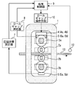
- FIG. FIG. 1 is a configuration diagram of a rolling mill using a plant control apparatus according to Embodiment 1 of the present invention.
- the following description is given for a control device that controls the plate thickness by rolling.
- the idea described below can be applied to control other than the plate thickness in various plants.
- the idea can be applied to control of the plate width, plate crown, flatness, and the like.
- the rolling stand for hot sheet rolling is a 4Hi mill.
- the rolling stand includes a housing 1.
- the upper work roll 2a and the lower work roll 2b are provided inside the housing 1 as rolling rolls.
- One side of the shaft of the upper work roll 2a is connected to an electric motor (not shown).
- the other side periphery of the upper work roll 2a is a work area.
- One side of the shaft of the lower work roll 2b is connected to an electric motor (not shown).
- the other side periphery of the lower work roll 2b is a work area.
- the upper backup roll 3a is provided above the upper work roll 2a as a rolling roll.
- the upper backup roll 3a supports the upper work roll 2a.
- the upper backup roll 3 a is supported on the upper part of the housing 1.
- the lower periphery of one side of the upper backup roll 3a becomes an existence area on one side of the axis of the upper work roll 2a and one side of the axis of the lower work roll 2b.
- the other side periphery of the upper backup roll 3a is a work area.
- the lower backup roll 3b is provided below the lower work roll 2b as a rolling roll.
- the lower backup roll 3b supports the lower work roll 2b.
- the lower backup roll 3 b is supported at the lower part of the housing 1.
- the lower backup roll 3b is provided below the floor surface.
- Above the lower backup roll 3b is a work area.
- the upper periphery of one side of the lower backup roll 3b becomes a region existing on one side of the axis of the upper work roll 2a and one side of the axis of the lower work roll 2b.
- the other side periphery of the lower backup roll 3b is a work area.
- the reduction device 4 is provided above the upper backup roll 3a.
- the reduction device 4 is an electric reduction device.
- the reduction device 4 is a hydraulic reduction device that is driven by hydraulic pressure.
- the hydraulic reduction device can be controlled at high speed.
- the reduction device 4 includes a one-side reduction device 4a and another-side reduction device 4b.
- the one side reduction device 4a is provided on one side of the upper backup roll 3a.
- the other side reduction device 4b is provided on the other side of the upper backup roll 3a.
- the load detector 5 is provided below the lower backup roll 3b.
- the load detector 5 includes a one-side load detector 5a and an other-side load detector 5b.
- the one-side load detector 5a is provided on one side of the lower backup roll 3b.
- the other side load detector 5b is provided on the other side of the upper backup roll 3a.
- the roll gap detector 6 is provided below the reduction device 4.
- the roll gap detector 6 includes a one-side roll gap detector 6a and an other-side roll gap detector 6b.
- the one-side roll gap detector 6a is provided on one side of the upper backup roll 3a.
- the other side roll gap detector 6b is provided on the other side of the upper backup roll 3a.
- the input side of the rolling load measuring device 7 is connected to the output side of the load detector 5.
- the input side of the roll gap measuring device 8 is connected to the output side of the roll gap detector 6.
- the input side of the plate thickness controller 9 is connected to the output side of the rolling load measuring device 7.
- the input side of the plate thickness controller 9 is connected to the output side of the roll gap measuring device 8.
- the input side of the roll gap operating means 10 is connected to the output side of the plate thickness controller 9.
- the output side of the roll gap operating means 10 is connected to the input side of the reduction device 4.
- the thickness gauge 12 is provided on the exit side of the rolling stand as a sensor.
- the output side of the thickness gauge 12 is connected to the input side of the thickness controller 9.
- the rolled material 13 is made of metal.
- the rolled material 13 is formed of iron.
- the rolled material 13 is formed of aluminum.
- the rolled material 13 is formed of copper.
- Rolled material 13 is sandwiched between rotating upper work roll 2a and lower work roll 2b. As a result, the rolled material 13 extends thinly.
- the upper backup roll 3a suppresses the deflection in the width direction of the upper work roll 2a.
- the lower backup roll 3b suppresses the deflection in the width direction of the lower work roll 2b.
- the one side load detector 5a detects a load applied to one side of the lower backup roll 3b.
- the other side load detector 5b detects a load applied to the other side of the lower backup roll 3b.
- the rolling load measuring device 7 calculates the sum of the detected value of the one side load detector 5a and the detected value of the other side load detector 5b as a sum load.
- the rolling load measuring device 7 calculates the difference between the detected value of the one side load detector 5a and the detected value of the other side load detector 5b as a differential load.
- a roll bending apparatus not shown
- the rolling load measuring device 7 performs calculation when correcting the detection value of the load detector 5 with the roll bending force.
- the roll gap detector 6 does not directly detect the gap (roll gap) between the upper work roll 2a and the lower work roll 2b.
- the roll gap detector 6 detects the amount by which the reduction device 4 pushes down the upper backup roll 3a.
- the roll gap measuring device 8 calculates the roll gap based on the detection value of the roll gap detector 6. At this time, the roll gap measuring device 8 considers the positional relationship among the upper backup roll 3a, the upper work roll 2a, the lower work roll 2b, the lower backup roll 3b, and the like.
- the plate thickness controller 9 adjusts the set value of the roll gap based on the calculated value of the rolling load measuring device 7 and the calculated value of the roll gap measuring device 8. Here, the plate thickness controller 9 adjusts the setting value of the roll gap with the mill modulus M C and plastic coefficient Q C.
- the roll gap operating means 10 adjusts the roll gap based on the set value adjusted by the plate thickness controller 9. As a result, the rolled material 13 has a desired plate thickness.
- the plate thickness of the rolled material 13 is measured by a plate thickness meter 12.
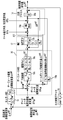
- FIG. 2 is a control block diagram for illustrating the plant control apparatus according to Embodiment 1 of the present invention.
- the rolling process 14 to be controlled is affected by the mill constant M and the plasticity factor Q.
- the rolling process 14 includes a first influence coefficient 14a and a second influence coefficient 14b.
- the first influence coefficient 14a corresponds to the influence of the roll gap on the rolling load.
- the first influence coefficient 14a is ⁇ MQ / (M + Q).
- the second influence coefficient 14b corresponds to the influence of the rolling load on the plate thickness.
- the second influence coefficient 14b is 1 / M.
- the rolling process 14 is considered the roll eccentricity disturbance [Delta] S D and the rolling load disturbance [Delta] P D is applied. Can not be detected roll eccentricity disturbance [Delta] S D directly. Rolling load disturbance [Delta] P D are included in the rolling load to be measured. Only the rolling load disturbance ⁇ P D cannot be measured separately.
- the plate thickness controller 9 implements a monitor AGC 15, a gauge meter AGC 16, an MMC (mill constant variable control) 17, etc. for the rolling process 14.
- the dead time block 18 is a sheet thickness meter from the center of the upper work roll 2a and the lower work roll 2b when the actual change amount ⁇ h ACT of the rolled material 13 rolled by the upper work roll 2a and the lower work roll 2b. 12 shows that the plate thickness meter 12 detects the change in plate thickness measurement value ⁇ h MES after the time TL transported to 12 has elapsed. Time TL is a dead time.
- the monitor AGC 15 calculates the gauge meter plate thickness target value change amount ⁇ h REF based on the deviation between the product plate thickness target value change amount ⁇ h X REF and the plate thickness measured value change amount ⁇ h MES .
- the first control block 16a is generally expressed using a mill modulus M C measured in actual.
- a coefficient ⁇ 1 for adjusting the response is added to the first control block 16a.
- the gauge meter plate thickness change amount ⁇ h GM is obtained.
- the gauge meter plate thickness target value change amount ⁇ h GM AIM and the gauge meter plate thickness target value change amount ⁇ h REF are added together.
- the plate thickness target value change amount ⁇ h GM REF is obtained.
- the deviation between the plate thickness target value change amount ⁇ h GM REF and the gauge meter plate thickness change amount ⁇ h GM is input to the PI controller 16b.
- the PI controller 16b is represented by a proportional gain KPG , an integral gain KIG, and a Laplace operator s.
- the roll gap symbol S is used with a subscript, ⁇ , and the like.
- the output of the PI controller 16b is input to the compensation gain 16c.
- the compensation gain 16c is represented by the identified mill constant M C , plastic coefficient Q C , and coefficients ⁇ 1 and ⁇ 2 for adjusting the response.
- plastic coefficient Q C is calculated separately off-line.
- plastic coefficient Q C is of values identified by the actual data.
- the compensation gain 16c calculates a roll gap command value ⁇ S SET . At this time, the compensation gain 16c normalizes the operation output. In this case, adjustment of the PI controller 16b is not necessary even if the mill constant M, plastic coefficient Q, and coefficients ⁇ 1 and ⁇ 2 to be controlled change.
- the MMC 17 requests the reduction device 4 for a high-speed response. For this reason, the MMC 17 is not applied when the reduction device 4 is not a hydraulic reduction device that can realize a high-speed response.
- second control block 17a is represented using mill modulus M C identified.
- MMC17 by adjusting the coefficient alpha 2 of the second control block 17a, may adjust the response. For example, by increasing the coefficient alpha 2, the response becomes faster.
- the hydraulic pressure reduction response 17b corresponds to the response of the hydraulic pressure reduction device.
- the hydraulic pressure reduction response 17b is determined based on a value obtained by superimposing the output of the compensation gain 16c and the output of the second control block 17a. As a result, the roll gap is adjusted.
- FIG. 3 is a simplified control block diagram for explaining the outline of the plant control apparatus according to Embodiment 1 of the present invention.
- the monitor AGC 15 is represented by one block.
- the gauge meter AGC 16 is represented by one block.
- the MMC 17 is represented by one block.
- the dead time block 18 is represented by one block.
- FIG. 4 is a diagram for explaining the overall configuration of the plant control apparatus according to Embodiment 1 of the present invention.
- the control device is represented by a dead time corresponding correction repeat controller 20, a round transfer function 21, and a control block diagram 22.
- the control deviation e is represented by the difference between the target value or the command value r and the feedback control amount value y 2.
- the control deviation e is input to the dead time corresponding correction repeat controller 20.
- Dead time corresponding modified repetitive controller 20 calculates the operation amount u 1.
- the manipulated variable u 1 is input to the round transfer function 21.
- the round transfer function 21 corresponds to a block obtained by combining the gauge meters AGC 16 and MMC 17 and the rolling process 14 of FIG.
- the round transfer function 21 is a system that does not include dead time.
- the round transfer function 21 outputs a signal y 1 to be controlled.
- Signal y 1 is input to control block diagram 22.
- the control block diagram 22 corresponds to the dead time block 18 of FIG.
- the control block diagram 22 represents the dead time.
- Control block diagram 22 outputs a signal y 2.
- the signal y 2 is delayed by a dead time with respect to the signal y 1 .
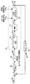
- FIG. 5 is a control block diagram using the plant control apparatus according to Embodiment 1 of the present invention.
- FIG. 5 is a diagram in which the rolling process 14, the gauge meters AGC 16, and the MMC 17 of FIG. 3 are applied to the circular transfer function 21 of FIG. 4.
- the control block diagram 22 of FIG. 4 is replaced by the dead time block 18 of FIG. If the block of FIG. 2 is used, it can expand
- the dead time corresponding correction repeat controller 20 is inserted between the control deviation e and the monitor AGC 15 with respect to the existing control system.
- the transmission coefficient of the monitor AGC 15 in FIG. 3 is set to “1”.
- the function of the monitor AGC 15 is not used.
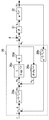
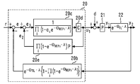
- FIG. 6 is a control block diagram of the main part of the plant control apparatus according to Embodiment 1 of the present invention.
- the dead time corresponding correction repeat controller 20 includes a block 20a, a block 20b, a block 20c, a block 20d, and a block 20e.
- Block 20c is a block in which repetitive controllers are collected.
- q is a low pass filter.
- the low-pass filter q is described by a first-order lag system.
- Block 20d is a stabilization compensator C.
- the block 20d is represented by a gain or the like.
- Block 20e is a dead time compensator that compensates for the dead time.
- the block 20e is a Smith compensator.
- the block 20e sets the period L [s] of the disturbance as a dead time. That is, the block 20e adds and outputs the signal delayed by L [s] when the signal is input and the signal as it is without delaying the input signal.
- L [s] is known.
- the dead time L [s] can be specified.
- the period of the roll eccentric disturbance synchronized with the rotation of the rolling roll can be calculated based on the roll diameter and the roll rotation speed.
- the block 20a is an operation delay device.
- Block 20a is a time delay L-T L [s] only control deviation e, and outputs a signal e 1.
- Signal e 1 is added to the signal e 2 side out of the block 20e.
- the signal e 3 is produced.
- the block 20a can be equivalently arranged at the position of the block 20b. For this reason, in actual control, one of the block 20a and the block 20b is used. At this time, the transfer function of the unused block is set to “1”.
- a round transfer function L 1 (s) from the signal e 1 to the manipulated variable u 1 is expressed by the following equation (1).
- the closed loop transfer function G CL1 (s) is expressed by the following equation (2) using the equation (1). In the following, the development of expressions in the middle is omitted as appropriate.
- the low-pass filter q is set to be approximately 1 in the frequency band of the disturbance d.
- the low-pass filter q has the same value every period L. Therefore, the following expressions (3) and (4) are established.
- the expression (5) means that the influence from the disturbance d to the control amount y 2 is almost zero. That is, the dead time corresponding correction repeat controller 20 effectively exhibits a disturbance suppressing force.
- the transfer function G CL2 (s) from the target value r to the control amount y 2 will be described.
- the transfer function G CL2 (s) is expressed by the following equation (6).
- Equation (7) means that the influence from the target value r to the control amount y 2 is almost 1. In other words, the dead time corresponding modified repetitive controller 20 causes the controlled variable y 2 follow well the target value r.
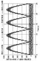
- FIG. 7 is a diagram for explaining functions of the plant control apparatus according to Embodiment 1 of the present invention.
- the upper part of FIG. 7 shows the plate thickness actual variation ⁇ h ACT (solid line) and the plate thickness measured value variation ⁇ h MES (broken line) when the rolling speed is constant.
- the sheet thickness actual variation ⁇ h ACT is conveyed from the rolling stand to the sheet thickness meter 12.
- the plate thickness meter 12 measures the plate thickness measurement value change amount ⁇ h MES .
- the signal of the actual thickness change amount ⁇ h ACT corresponding to the phenomenon occurring immediately below the rolling stand at that time is changed.
- the timing of the operation amount by the control device is shifted by the amount of the dead time TL from the timing of the change in sheet thickness that occurs immediately below the rolling stand. For this reason, good control cannot be performed.
- the control unit delays the signal having a thickness measurement variation ⁇ h MES L-T L [s ] only.
- the signal timing of the plate thickness measurement value change amount ⁇ h MES matches the signal timing of the plate thickness actual change amount ⁇ h ACT .
- the lower part of FIG. 7 shows a plate thickness actual change amount ⁇ h ACT (solid line) and a plate thickness measured value change amount ⁇ h MES (broken line) when the rolling speed increases.
- control according to changes in the period of the disturbance and the dead time is performed.
- the signal timing of the plate thickness measurement value change amount ⁇ h MES matches the signal timing of the plate thickness actual change amount ⁇ h ACT .
- the input of the operation amount to the operation end is delayed by the time obtained by subtracting the dead time from the time for one period of the disturbance. For this reason, when a periodic disturbance is added to the controlled object of the plant including the dead time, the influence of the disturbance can be suppressed and high control performance can be obtained.
- board thickness of the rolling material 13 can be controlled accurately.
- the dead time is compensated by the dead time compensator. For this reason, even when the dead time changes, the influence of the disturbance can be suppressed and high control performance can be obtained.
- FIG. 8 is a diagram for explaining a modification of the plant control apparatus according to Embodiment 1 of the present invention.
- eccentricity disturbance [Delta] S D is a disturbance which depends on the rotation and the rotation of the lower backup roll 3b of the upper backup roll 3a.
- the rolling load disturbance ⁇ P D is a temperature disturbance at a constant distance interval based on a skid mark applied to the rolled material inside the heating furnace.
- Rolling load disturbance [Delta] P D is conceivable as a disturbance having a distance of a multiple of the circumference of the outer and lower backup roll 3b of the upper backup roll 3a. For this reason, control based on the angle ⁇ of the rotating body, that is, the upper backup roll 3a and the lower backup roll is performed.
- the control based on the angle ⁇ of the rotating body is realized by describing the Laplace transform expressed by the following equation (8) by the conversion expressed by the equation (9).
- t time.
- s is a Laplace operator.
- ⁇ is an operator in an angle region corresponding to the Laplace operator s.
- FIG. 8 is a representation of FIG. 1 with the transformation of equation (9).
- the block 20a of FIG. 1 is omitted.
- one of the block 20a and the block 20b is used.
- the transfer function of the unused block is set to “1”.
- i is a disturbance number to be controlled. i is represented by 1, 2,.
- ⁇ REP is obtained by converting the period of disturbance into an area based on an angle.
- exp ( ⁇ REP ⁇ ⁇ ) is a dead time expressed in angle.
- ⁇ TL is obtained by converting the dead time from the rolling stand to the plate thickness meter 12 into a region based on the angle.
- exp ( ⁇ TL ⁇ ⁇ ) is a dead time expressed in angle.
- ⁇ is a mathematical symbol that means multiplying the elements inside. Specifically, ⁇ is expressed by the following equation (10).
- the cyclic controller learns the eccentricity amount by associating the periodic position of the upper backup roll 3a or the periodic position of the lower backup roll 3b with the eccentricity amount. As a result, the roll eccentricity disturbance [Delta] S D is appropriately controlled.
- FIG. 9 is a diagram for explaining roll eccentric disturbance and rolling load disturbance applied to the plant control apparatus according to Embodiment 1 of the present invention.
- a roll eccentricity disturbance [Delta] S D and the rolling load disturbance [Delta] P D may be considered periodic disturbances.
- the roll eccentricity mainly depends on the eccentricity of the upper backup roll 3a and the eccentricity of the lower backup roll 3b. For this reason, roll eccentricity occurs according to the rotation cycle of the upper backup roll 3a and the rotation cycle of the lower backup roll 3b.
- Rolling load disturbance ⁇ P D is based on the skid marks.
- the skid mark is given to the rolled material by supporting the rolled material with skids arranged at substantially constant intervals in the heating furnace.
- the skid is a column whose interior is water-cooled. For this reason, the temperature of the rolling material is lower than the other positions at the position of the skid mark. As a result, the rolled material is harder than the other positions at the skid mark position. At this time, if the roll gap is constant, the rolled material is thicker at the skid mark position than at other positions.
- Rolling load disturbance [Delta] P D shaped like a full wave of rolling load wave of FIG. 9 is obtained.
- the frequency of roll eccentricity disturbance [Delta] S D is higher than the frequency of the rolling load disturbance [Delta] P D.
- the shape of the roll eccentric wave of FIG. 7 is obtained.
- the superimposed waveform of FIG. 7 is obtained.
- the disturbance d of FIG. 6 and FIG. 8 dates back to the gauge meter AGC16 via MMC17 from rolling process 14 from the roll eccentricity disturbance [Delta] S D and the rolling load disturbance [Delta] P D of FIGS. 2 and 3 and 5 Is obtained.
- control based on the angle of the rotating body may be performed as in the modified example. In this case, even if the period of the disturbance and the dead time are changed by changing the speed of the rolled material, the influence of the disturbance can be suppressed and high control performance can be easily obtained.
- the control can be easily performed.
- FIG. 10 is a hardware configuration diagram of the plant control apparatus according to Embodiment 1 of the present invention.
- Each function of the control device can be realized by a processing circuit.
- the processing circuit includes at least one processor 23a and at least one memory 23b.
- the processing circuit comprises at least one dedicated hardware 24.
- each function of the control device is realized by software, firmware, or a combination of software and firmware. At least one of software and firmware is described as a program. At least one of software and firmware is stored in at least one memory 23b. At least one processor 23a implements each function of the control device by reading and executing a program stored in at least one memory 23b.
- the at least one processor 23a is also referred to as a CPU (Central Processing Unit), a central processing unit, a processing unit, an arithmetic unit, a microprocessor, a microcomputer, and a DSP.
- the at least one memory 23b is a nonvolatile or volatile semiconductor memory such as a RAM, a ROM, a flash memory, an EPROM, or an EEPROM, a magnetic disk, a flexible disk, an optical disk, a compact disk, a mini disk, a DVD, or the like.
- a nonvolatile or volatile semiconductor memory such as a RAM, a ROM, a flash memory, an EPROM, or an EEPROM, a magnetic disk, a flexible disk, an optical disk, a compact disk, a mini disk, a DVD, or the like.
- the processing circuit comprises at least one dedicated hardware 24, the processing circuit is, for example, a single circuit, a composite circuit, a programmed processor, a parallel programmed processor, an ASIC, an FPGA, or a combination thereof. is there.
- each function of the control device is realized by a processing circuit.
- each function of the control device is collectively realized by a processing circuit.
- control device may be realized by dedicated hardware 24, and the other part may be realized by software or firmware.
- the function of the dead time corresponding correction repeat controller 20 is realized by a processing circuit as dedicated hardware 24, and at least one processor 23a has at least one memory for functions other than the dead time correction repeat controller 20. You may implement
- the processing circuit realizes each function of the control device by the hardware 24, software, firmware, or a combination thereof.
- FIG. FIG. 11 is a control block diagram for illustrating a plant control apparatus according to Embodiment 2 of the present invention.
- symbol is attached
- the control block diagram of FIG. 11 is obtained by adding a changeover switch 25 to the control block diagram of FIG.
- One of the input sides of the changeover switch 25 is connected to the output side of the monitor AGC 15.
- the other input side of the changeover switch 25 is connected to the output side of the dead time corresponding correction repeat controller 20.
- the operation end is corrected via the time delay correcting correction controller 20. Whether or not to input an operation amount can be immediately selected. As a result, a flexible control system can be obtained. For example, it is possible to easily compare the control performance depending on the presence / absence of the dead time corresponding correction repeat controller 20. When it becomes inconvenient due to the addition of the dead time correction correction repeat controller 20, the dead time correction correction repeat controller 20 can be immediately disconnected.
- Embodiment 1 and Embodiment 2 may apply the control apparatus of Embodiment 1 and Embodiment 2 to mills other than 4Hi mill.
- the dead time corresponding correction repeat controller 20 may be applied to a plant control device other than the rolling mill. Also in this case, when a periodic disturbance is applied to the plant control apparatus including the dead time, the influence of the disturbance can be suppressed and high control performance can be obtained.
- the plant control apparatus can be used for a system that suppresses the influence of the disturbance and obtains high control performance when a periodic disturbance is applied to the plant control apparatus including dead time. .
Landscapes
- Engineering & Computer Science (AREA)
- Mechanical Engineering (AREA)
- Software Systems (AREA)
- Computer Vision & Pattern Recognition (AREA)
- Evolutionary Computation (AREA)
- Medical Informatics (AREA)
- Health & Medical Sciences (AREA)
- Physics & Mathematics (AREA)
- General Physics & Mathematics (AREA)
- Automation & Control Theory (AREA)
- Artificial Intelligence (AREA)
- Control Of Metal Rolling (AREA)
- Feedback Control In General (AREA)
Abstract
Description
図1はこの発明の実施の形態1におけるプラントの制御装置を利用した圧延機の構成図である。以下の説明は、圧延による板厚を制御する制御装置を対象に行われる。以下の説明による考えは、各種プラントにおいて、板厚以外の制御に対しても適用できる。例えば、当該考えは、板幅、板クラウン、平坦度等の制御に対しても適用できる。
図2はこの発明の実施の形態1におけるプラントの制御装置を説明するための制御ブロック図である。
図3はこの発明の実施の形態1におけるプラントの制御装置の概要を説明するための制御ブロック図を簡略化した図である。
図4はこの発明の実施の形態1におけるプラントの制御装置の全体構成を説明するための図である。
図5はこの発明の実施の形態1におけるプラントの制御装置を利用した制御ブロック図である。
図6はこの発明の実施の形態1におけるプラントの制御装置の要部の制御ブロック図である。

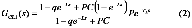
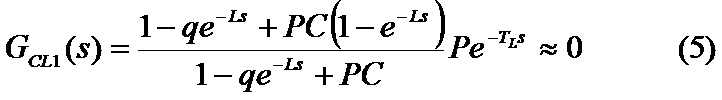


図7はこの発明の実施の形態1におけるプラントの制御装置の機能を説明するための図である。
図8はこの発明の実施の形態1におけるプラントの制御装置の変形例を説明するための図である。
図9はこの発明の実施の形態1におけるプラントの制御装置に加わるロール偏芯外乱と圧延荷重外乱を説明するための図である。
図10はこの発明の実施の形態1におけるプラントの制御装置のハードウェア構成図である。
図11はこの発明の実施の形態2におけるプラントの制御装置を説明するための制御ブロック図である。なお、実施の形態1と同一又は相当部分には同一符号を付して説明を省略する。
Claims (5)
- 周期的な外乱が加わるプラントの制御量に対する目標値が与えられ、センサで測定される制御量を前記目標値とするための操作端の操作量の変更結果が前記センサで測定されるまでにむだ時間が生じる場合に、外乱の周期およびむだ時間の変化に応じて外乱の1周期分の時間からむだ時間を差し引いた時間だけ前記操作端への前記操作量の入力を遅らせるむだ時間対応修正繰返し制御器、
を備えたプラントの制御装置。 - 前記むだ時間対応修正繰返し制御器は、
外乱の周期およびむだ時間の変化に応じて外乱の1周期分の時間からむだ時間を差し引いた時間だけ前記操作端への操作量への入力を遅らせる操作遅延器と、
外乱の周期およびむだ時間の変化に応じてむだ時間を補償するむだ時間補償器と、
を備えた請求項1に記載のプラントの制御装置。 - 前記むだ時間対応修正繰返し制御器は、外乱の周期が前記プラントに設けられた回転体の周期の定数倍の周期に応じて変化する場合に前記回転体の角度を規準とした制御を行う請求項1または請求項2に記載のプラントの制御装置。
- 前記むだ時間対応修正繰返し制御器は、前記定数倍がNを整数として1/N倍またはN倍の場合に前記回転体の角度を規準とした制御を行う請求項3に記載のプラントの制御装置。
- 前記むだ時間対応修正繰返し制御器を介して前記操作端への操作量の入力を行うか否かを選択し得るように設けられた切り替えスイッチ、
を備えた請求項1から請求項4のいずれか一項に記載のプラントの制御装置。
Priority Applications (5)
| Application Number | Priority Date | Filing Date | Title |
|---|---|---|---|
| JP2018501425A JP6597877B2 (ja) | 2016-02-22 | 2016-02-22 | プラントの制御装置 |
| CN201680059213.9A CN108136461B (zh) | 2016-02-22 | 2016-02-22 | 工厂设备的控制装置 |
| PCT/JP2016/055061 WO2017145236A1 (ja) | 2016-02-22 | 2016-02-22 | プラントの制御装置 |
| KR1020187009107A KR102049682B1 (ko) | 2016-02-22 | 2016-02-22 | 플랜트의 제어 장치 |
| TW105111789A TWI591462B (zh) | 2016-02-22 | 2016-04-15 | 工廠之控制裝置 |
Applications Claiming Priority (1)
| Application Number | Priority Date | Filing Date | Title |
|---|---|---|---|
| PCT/JP2016/055061 WO2017145236A1 (ja) | 2016-02-22 | 2016-02-22 | プラントの制御装置 |
Publications (1)
| Publication Number | Publication Date |
|---|---|
| WO2017145236A1 true WO2017145236A1 (ja) | 2017-08-31 |
Family
ID=59684945
Family Applications (1)
| Application Number | Title | Priority Date | Filing Date |
|---|---|---|---|
| PCT/JP2016/055061 Ceased WO2017145236A1 (ja) | 2016-02-22 | 2016-02-22 | プラントの制御装置 |
Country Status (5)
| Country | Link |
|---|---|
| JP (1) | JP6597877B2 (ja) |
| KR (1) | KR102049682B1 (ja) |
| CN (1) | CN108136461B (ja) |
| TW (1) | TWI591462B (ja) |
| WO (1) | WO2017145236A1 (ja) |
Cited By (2)
| Publication number | Priority date | Publication date | Assignee | Title |
|---|---|---|---|---|
| CN110716430A (zh) * | 2019-09-27 | 2020-01-21 | 浙江工业大学 | 一种采用等效扰动补偿的伺服系统快速吸引重复控制方法 |
| CN116360273A (zh) * | 2023-05-06 | 2023-06-30 | 山东金都工程设计咨询有限公司 | 一种锂辉石选矿重介质液密度史密斯补偿控制方法 |
Families Citing this family (5)
| Publication number | Priority date | Publication date | Assignee | Title |
|---|---|---|---|---|
| JP2019040437A (ja) * | 2017-08-25 | 2019-03-14 | アズビル株式会社 | 調節計および劣化位置検出方法 |
| JP6943683B2 (ja) * | 2017-08-25 | 2021-10-06 | アズビル株式会社 | 調節計および劣化位置検出方法 |
| TWI670124B (zh) * | 2018-11-12 | 2019-09-01 | 中國鋼鐵股份有限公司 | 鋼帶厚度控制方法 |
| JP6683270B1 (ja) * | 2019-02-04 | 2020-04-15 | オムロン株式会社 | 外乱抑制装置、外乱抑制方法、およびプログラム |
| KR102536442B1 (ko) * | 2020-01-15 | 2023-05-26 | 도시바 미쓰비시덴키 산교시스템 가부시키가이샤 | 압연 제어 시스템 및 압연 제어 방법 |
Citations (4)
| Publication number | Priority date | Publication date | Assignee | Title |
|---|---|---|---|---|
| JPS6227884B2 (ja) * | 1982-11-15 | 1987-06-17 | Nitsushin Seiko Kk | |
| JPH0538176A (ja) * | 1991-07-24 | 1993-02-12 | Mitsubishi Electric Corp | 電動機速度制御装置 |
| JPH1177128A (ja) * | 1997-09-05 | 1999-03-23 | Toshiba Corp | 圧延機の板厚制御装置 |
| JP2002358125A (ja) * | 2001-06-04 | 2002-12-13 | Nec Corp | 位置決め制御装置及び位置決め制御方法 |
Family Cites Families (2)
| Publication number | Priority date | Publication date | Assignee | Title |
|---|---|---|---|---|
| WO2009136435A1 (ja) * | 2008-05-07 | 2009-11-12 | 東芝三菱電機産業システム株式会社 | 圧延機の板厚制御装置 |
| JP5817130B2 (ja) | 2011-01-27 | 2015-11-18 | Jfeスチール株式会社 | 熱間圧延ラインにおけるロール制御方法 |
-
2016
- 2016-02-22 KR KR1020187009107A patent/KR102049682B1/ko active Active
- 2016-02-22 CN CN201680059213.9A patent/CN108136461B/zh active Active
- 2016-02-22 JP JP2018501425A patent/JP6597877B2/ja active Active
- 2016-02-22 WO PCT/JP2016/055061 patent/WO2017145236A1/ja not_active Ceased
- 2016-04-15 TW TW105111789A patent/TWI591462B/zh active
Patent Citations (4)
| Publication number | Priority date | Publication date | Assignee | Title |
|---|---|---|---|---|
| JPS6227884B2 (ja) * | 1982-11-15 | 1987-06-17 | Nitsushin Seiko Kk | |
| JPH0538176A (ja) * | 1991-07-24 | 1993-02-12 | Mitsubishi Electric Corp | 電動機速度制御装置 |
| JPH1177128A (ja) * | 1997-09-05 | 1999-03-23 | Toshiba Corp | 圧延機の板厚制御装置 |
| JP2002358125A (ja) * | 2001-06-04 | 2002-12-13 | Nec Corp | 位置決め制御装置及び位置決め制御方法 |
Cited By (3)
| Publication number | Priority date | Publication date | Assignee | Title |
|---|---|---|---|---|
| CN110716430A (zh) * | 2019-09-27 | 2020-01-21 | 浙江工业大学 | 一种采用等效扰动补偿的伺服系统快速吸引重复控制方法 |
| CN110716430B (zh) * | 2019-09-27 | 2022-05-03 | 浙江工业大学 | 一种采用等效扰动补偿的伺服系统快速吸引重复控制方法 |
| CN116360273A (zh) * | 2023-05-06 | 2023-06-30 | 山东金都工程设计咨询有限公司 | 一种锂辉石选矿重介质液密度史密斯补偿控制方法 |
Also Published As
| Publication number | Publication date |
|---|---|
| CN108136461B (zh) | 2019-10-01 |
| TW201730703A (zh) | 2017-09-01 |
| KR20180048915A (ko) | 2018-05-10 |
| JP6597877B2 (ja) | 2019-10-30 |
| TWI591462B (zh) | 2017-07-11 |
| CN108136461A (zh) | 2018-06-08 |
| JPWO2017145236A1 (ja) | 2018-09-20 |
| KR102049682B1 (ko) | 2019-11-28 |
Similar Documents
| Publication | Publication Date | Title |
|---|---|---|
| JP6597877B2 (ja) | プラントの制御装置 | |
| CN105492133B (zh) | 轧机的板厚控制装置 | |
| KR101639145B1 (ko) | 금속 판재의 압연 장치 | |
| US20210394245A1 (en) | Plate thickness control device and plate thickness control method | |
| JP7765517B2 (ja) | 冷間圧延機のための拡張カルマンフィルタ状態推定を使用する動的ロール偏心識別及び制御アップグレード | |
| JP6296168B2 (ja) | プラントの制御装置 | |
| CN108568454A (zh) | 轧制控制装置以及轧制控制方法 | |
| CN104722584B (zh) | 用于多机架轧机的宽度控制装置和方法 | |
| JP2017070954A (ja) | 蛇行制御装置、圧延システムおよび蛇行制御方法 | |
| KR102367345B1 (ko) | 플랜트 제어 장치 및 플랜트 제어 방법 | |
| JP5557726B2 (ja) | 圧延機の板厚制御方法及び板厚制御装置 | |
| JPH02137607A (ja) | 熱間連続圧延機のルーパー制御方法 | |
| JP4256827B2 (ja) | 金属板材の圧延方法および圧延装置 | |
| JP6299682B2 (ja) | 金属ストリップの蛇行制御方法及び蛇行制御装置 | |
| CN112154382B (zh) | 钢铁设备控制装置 | |
| JP2023533739A (ja) | 周波数挙動を考慮に入れた圧延 | |
| JPH0413408A (ja) | 板厚制御方法 | |
| JPH01293913A (ja) | 板圧延形状制御方法 | |
| JPH06114427A (ja) | 圧延機の自動板厚制御方法 | |
| JPS63123512A (ja) | 圧延機の制御方法 |
Legal Events
| Date | Code | Title | Description |
|---|---|---|---|
| ENP | Entry into the national phase |
Ref document number: 20187009107 Country of ref document: KR Kind code of ref document: A |
|
| ENP | Entry into the national phase |
Ref document number: 2018501425 Country of ref document: JP Kind code of ref document: A |
|
| NENP | Non-entry into the national phase |
Ref country code: DE |
|
| 121 | Ep: the epo has been informed by wipo that ep was designated in this application |
Ref document number: 16891395 Country of ref document: EP Kind code of ref document: A1 |
|
| 122 | Ep: pct application non-entry in european phase |
Ref document number: 16891395 Country of ref document: EP Kind code of ref document: A1 |