WO2017145257A1 - Dispositif d'antenne réseau et son procédé d'étalonnage - Google Patents
Dispositif d'antenne réseau et son procédé d'étalonnage Download PDFInfo
- Publication number
- WO2017145257A1 WO2017145257A1 PCT/JP2016/055212 JP2016055212W WO2017145257A1 WO 2017145257 A1 WO2017145257 A1 WO 2017145257A1 JP 2016055212 W JP2016055212 W JP 2016055212W WO 2017145257 A1 WO2017145257 A1 WO 2017145257A1
- Authority
- WO
- WIPO (PCT)
- Prior art keywords
- transmission
- reception
- signal
- circuit
- calibration
- Prior art date
- Legal status (The legal status is an assumption and is not a legal conclusion. Google has not performed a legal analysis and makes no representation as to the accuracy of the status listed.)
- Ceased
Links
Images


Classifications
-
- H—ELECTRICITY
- H01—ELECTRIC ELEMENTS
- H01Q—ANTENNAS, i.e. RADIO AERIALS
- H01Q3/00—Arrangements for changing or varying the orientation or the shape of the directional pattern of the waves radiated from an antenna or antenna system
- H01Q3/26—Arrangements for changing or varying the orientation or the shape of the directional pattern of the waves radiated from an antenna or antenna system varying the relative phase or relative amplitude of energisation between two or more active radiating elements; varying the distribution of energy across a radiating aperture
- H01Q3/267—Phased-array testing or checking devices
-
- H—ELECTRICITY
- H04—ELECTRIC COMMUNICATION TECHNIQUE
- H04B—TRANSMISSION
- H04B1/00—Details of transmission systems, not covered by a single one of groups H04B3/00 - H04B13/00; Details of transmission systems not characterised by the medium used for transmission
- H04B1/38—Transceivers, i.e. devices in which transmitter and receiver form a structural unit and in which at least one part is used for functions of transmitting and receiving
- H04B1/40—Circuits
- H04B1/44—Transmit/receive switching
-
- G—PHYSICS
- G01—MEASURING; TESTING
- G01S—RADIO DIRECTION-FINDING; RADIO NAVIGATION; DETERMINING DISTANCE OR VELOCITY BY USE OF RADIO WAVES; LOCATING OR PRESENCE-DETECTING BY USE OF THE REFLECTION OR RERADIATION OF RADIO WAVES; ANALOGOUS ARRANGEMENTS USING OTHER WAVES
- G01S7/00—Details of systems according to groups G01S13/00, G01S15/00, G01S17/00
- G01S7/02—Details of systems according to groups G01S13/00, G01S15/00, G01S17/00 of systems according to group G01S13/00
- G01S7/40—Means for monitoring or calibrating
- G01S7/4004—Means for monitoring or calibrating of parts of a radar system
-
- H—ELECTRICITY
- H01—ELECTRIC ELEMENTS
- H01Q—ANTENNAS, i.e. RADIO AERIALS
- H01Q21/00—Antenna arrays or systems
- H01Q21/0006—Particular feeding systems
- H01Q21/0025—Modular arrays
-
- H—ELECTRICITY
- H01—ELECTRIC ELEMENTS
- H01Q—ANTENNAS, i.e. RADIO AERIALS
- H01Q3/00—Arrangements for changing or varying the orientation or the shape of the directional pattern of the waves radiated from an antenna or antenna system
- H01Q3/26—Arrangements for changing or varying the orientation or the shape of the directional pattern of the waves radiated from an antenna or antenna system varying the relative phase or relative amplitude of energisation between two or more active radiating elements; varying the distribution of energy across a radiating aperture
-
- H—ELECTRICITY
- H04—ELECTRIC COMMUNICATION TECHNIQUE
- H04B—TRANSMISSION
- H04B17/00—Monitoring; Testing
- H04B17/10—Monitoring; Testing of transmitters
- H04B17/11—Monitoring; Testing of transmitters for calibration
- H04B17/12—Monitoring; Testing of transmitters for calibration of transmit antennas, e.g. of the amplitude or phase
-
- H—ELECTRICITY
- H04—ELECTRIC COMMUNICATION TECHNIQUE
- H04B—TRANSMISSION
- H04B17/00—Monitoring; Testing
- H04B17/20—Monitoring; Testing of receivers
- H04B17/21—Monitoring; Testing of receivers for calibration; for correcting measurements
- H04B17/22—Monitoring; Testing of receivers for calibration; for correcting measurements for calibration of the receiver components
- H04B17/221—Monitoring; Testing of receivers for calibration; for correcting measurements for calibration of the receiver components of receiver antennas, e.g. as to amplitude or phase
-
- H—ELECTRICITY
- H04—ELECTRIC COMMUNICATION TECHNIQUE
- H04B—TRANSMISSION
- H04B7/00—Radio transmission systems, i.e. using radiation field
- H04B7/02—Diversity systems; Multi-antenna system, i.e. transmission or reception using multiple antennas
- H04B7/04—Diversity systems; Multi-antenna system, i.e. transmission or reception using multiple antennas using two or more spaced independent antennas
- H04B7/06—Diversity systems; Multi-antenna system, i.e. transmission or reception using multiple antennas using two or more spaced independent antennas at the transmitting station
- H04B7/0686—Hybrid systems, i.e. switching and simultaneous transmission
- H04B7/0691—Hybrid systems, i.e. switching and simultaneous transmission using subgroups of transmit antennas
Definitions
- the present invention relates to an array antenna apparatus used for applications such as radar and wireless communication, and a calibration method thereof.
- the phased array antenna can scan the beam electronically with the array antenna device physically fixed, that is, by electrical control of the element antenna, it is possible to perform high-speed beam control and multi-beam formation. Therefore, it is used for applications such as radar and wireless communication.
- it is important to calibrate the initial variation of the transmission circuit and the reception circuit provided for each element antenna.
- the calibration of the array antenna device is usually performed using a measuring instrument in a test site such as an anechoic chamber.
- a calibration antenna is installed at a position away from the array antenna device by a predetermined distance so as to face the array antenna device.
- the array antenna device and the calibration antenna are connected to a measuring instrument.
- signals transmitted from the respective element antennas constituting the array antenna apparatus are sequentially received by the calibration antenna.
- the arithmetic unit calculates the variation between the signals, and calibration is performed to compensate for the variation.
- equipment for an anechoic chamber is usually large and measuring instruments are generally expensive, so capital investment is costly.
- a dedicated antenna is required because a calibration antenna is installed separately from the linear array antenna for calibration.
- the receiving linear array antenna is equipped with a receiving calibration antenna and the receiving linear array antenna is equipped with a transmitting calibration antenna, the calibration linear array antenna is limited to transmission only or reception only. Not applicable to array antennas.
- the array antenna array is limited to a linear shape, and cannot be applied to, for example, a planar array antenna generally used in radar, wireless communication, and the like.
- Patent Document 1 only the phase theoretically calculated from the wavelength and distance is corrected for the difference in distance between each element antenna of the linear array antenna and the calibration antenna, and the amplitude correction is taken into consideration. It has not been. Also, in the planar array antenna, the array of element antennas is various, such as the electric field surface direction, the magnetic field surface direction, and the oblique direction, so that there is a problem that appropriate phase correction cannot be performed with values theoretically calculated from the wavelength and distance. Arise.
- the present invention has been made to solve the above-described problems, and in an array antenna apparatus that includes an array antenna and a transmission / reception circuit and performs calibration by the array antenna apparatus itself, appropriately corrects amplitude and phase. It is an object of the present invention to obtain an array antenna device and a calibration method thereof.
- the present invention includes a plurality of element antennas, a transmission / reception module provided in each of the plurality of element antennas, having a transmission circuit, a reception circuit, and a transmission / reception switching unit, and a signal transmitter for generating a signal for transmission
- a distributor for distributing a signal output from the signal transmitter to the transmission circuits, a synthesizer for synthesizing signals received by the reception circuits, and a signal synthesized by the synthesizer
- a receiver having a signal detection unit for detecting the amplitude and phase of the received signal; and control and transmission / reception of the amplitude and phase of the signal passing through the transmission circuit and the reception circuit of each transmission / reception module according to a desired control signal
- a detection signal from the signal detection unit is transmitted between the element antennas of the transmission / reception module.
- a reception control unit that performs calibration of amplitude and phase of the receiving circuit and the transmitting circuit according to the calibration values
- the present invention can provide an array antenna apparatus and a calibration method thereof that can appropriately correct amplitude and phase in an array antenna apparatus that includes an array antenna and a transmission / reception circuit and performs calibration by the array antenna apparatus itself.
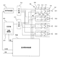
- FIG. 1 and 2 are diagrams schematically showing a configuration of an array antenna apparatus according to Embodiment 1 of the present invention.
- a transmission / reception module 200 is connected to each element antenna 100.
- a transmission amplification unit 211 with variable gain, a transmission phase shift unit 212, and a transmission operation switching switch 213 that is an operation switching unit that switches between operation and non-operation constitute a transmission circuit TC.
- the reception amplification unit 221 with variable gain, the reception phase shift unit 222, and the reception operation switching switch 223 that is an operation switching unit that switches between operation and non-operation constitute a reception circuit RC.
- a transmission / reception switching switch 231 that is a transmission / reception switching unit is provided between the element antenna 100 and the transmission circuit TC and the reception circuit RC.
- the signal from the signal transmitter 300 is distributed and supplied to each transmission / reception module 200 via the distributor 310.
- the reception signals of the respective transmission / reception modules 200 are combined by the combiner 410 and sent to the receiver 400.
- the element antenna 100, the transmission / reception module 200, the signal transmitter 300, the distributor 310, the receiver 400, and the combiner 410 represent the state of high-frequency signal exchange in the array antenna apparatus.
- the arrangement of the element antennas 100 is schematically drawn in a straight line, but the same applies to the case where the element antennas are arranged in a plane.
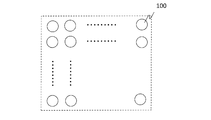
- FIG. 6 and 7 are front views, for example, viewed from the right side of FIG. 1, for illustrating an example of the arrangement of the element antennas 100.
- FIG. 6 shows a linear shape of the element antenna 100 as shown in FIG. 7 shows a case where the element antennas 100 are arranged vertically and horizontally in a planar shape.
- the case where the number of element antennas is four will be described below.
- the number of element antennas is not limited to this. It is sufficient that a plurality of element antennas are arranged.
- the receiver 400 includes a signal detector 420 that detects the amplitude and phase of the signal received by the array antenna apparatus.
- the detection result of the signal detection unit 420 is input to the transmission / reception control device 500 as a detection signal.
- the transmission / reception control apparatus 500 is a control unit of the array antenna apparatus
- FIG. 8 is a schematic functional block diagram of the transmission / reception control apparatus 500.
- 8 includes a transmission / reception control unit 510, a calibration signal calculation unit 520, and a storage unit 530.
- FIG. 9 is a diagram illustrating an example of a hardware configuration when the transmission / reception control device 500 is configured by a computer, for example.
- a transmission / reception control device 500 configured as a computer 500a inputs / outputs signals such as data to / from the signal transmitter 300, the receiver 400, each transmission / reception module 200, and other devices (not shown) via the interface 11.
- the memory 13 stores a program of functions shown in each functional block shown in FIG. 8 and data used for control processing.
- the data used for the control processing is the mutual coupling amplitude phase information 531 stored in the storage unit 530 shown in FIG.
- the processor 12 performs arithmetic processing on a signal input from the outside via the interface 11 according to the program and data stored in the memory 13, and outputs the arithmetic processing result via the interface 11.
- the human interface (HI) 14 includes a data input device and a display for the worker. Data is input from the HI 14 as necessary, or the state of the array antenna device is monitored by a display.
- the memory 13 corresponds to the storage unit 530 in FIG. Note that the transmission / reception control device 500 may be configured by a digital circuit for each functional block shown in FIG. 8, for example.
- the detection signal DS from the signal detection unit 420 is input to the calibration signal calculation unit 520.
- the calibration value CV which is the calculation result in the calibration signal calculation unit 520, is sent to the transmission / reception control unit 510.
- the calibration signal calculation unit 520 transmits and receives the detection signal of the signal detection unit 420 during the calibration operation among the mutual coupling amplitude phase information 531 stored in the storage unit 530 in advance. Correction is performed according to the mutual coupling amplitude phase information corresponding to the antennas 100. Further, a calibration value CV for compensating the corrected value with respect to the set value is obtained.
- the transmission / reception control unit 510 calibrates the amplitude and phase of the transmission circuit TC and the reception circuit RC according to the calibration value CV obtained by the calibration signal calculation unit 520.
- the transmission / reception control unit 510 or the calibration signal calculation unit 520 may output a calibration signal command CAS to the signal transmitter 300 and generate a signal dedicated to calibration from the signal transmitter 300.
- the transmission / reception control unit 510 performs transmission and reception of the transmission circuit TC of each transmission / reception module 200 and the amplification units 211 and 221 of the reception circuit RC according to a desired control signal CS for controlling the array antenna apparatus.
- the phase sections 212 and 222 and the operation switching switches 213 and 223 are controlled to control the amplitude and phase of signals passing through the transmission circuit TC and the reception circuit RC, and to switch transmission / reception to perform transmission / reception control. Further, switching between the transmission circuit TC and reception circuit RC of each transmission / reception module 200 and the element antenna 100 controls the transmission / reception switching switch 231.
- the control signal CS at the normal time is actually obtained from the received signal at the receiver 400 and other signals.
- the calibration of the array antenna apparatus is such that the reference amplitude value and phase value of the transmission circuit TC and the reception circuit RC of each transmission / reception module 200 are adjusted and matched so as to have desired set values.
- calibration is performed based on a detection signal DS obtained by receiving a signal transmitted from the element antenna 100 through one transmission circuit TC and passing through one reception circuit RC by the element antenna 100. Done.
- the obtained detection signal DS includes characteristics that the signal receives in the space between the transmitted element antenna and the received element antenna.
- the characteristics received by signals in the space between individual element antennas are obtained in advance and stored in the storage unit 530 as mutual coupling amplitude phase information. Then, calibration is performed by correcting the detection signal DS obtained at the time of calibration with the mutual coupling amplitude phase information.
- each transmission / reception module 200 connected to the element antennas E01, E02, E04 has the transmission / reception switching switch 231 connected to the transmission circuit TC side, and the transmission / reception module 200 connected to the element antenna E03 has the transmission / reception switching switch 231 received by the reception circuit. Connected to the RC side.
- the signal transmitter 300 outputs the routes E01 ⁇ E03, E02 ⁇ E03, E04 ⁇ E03 by sequentially switching the transmission operation switching switches 213 of the element antennas E01, E02, and E04 that are transmitting antennas.
- the signal information at the receiver 400 of the received signal can be obtained.
- the signal information is detected by the signal detection unit 420.
- each signal path usually has initial variations.
- the signal information obtained by the signal detection unit 420 includes variations in amplitude and phase.
- the physical distance between the element antennas is different, so that the space propagation conditions are also different, and a characteristic difference due to the influence is added.
- the arrangement direction is different in the electric field surface direction, magnetic field surface direction, diagonal direction, etc. Conditions are different.
- the mutual coupling amplitude phase information between the element antennas 100 is acquired in advance, and the detection signal DS having the signal information respectively obtained by the signal detection unit 420 is corrected with the mutual coupling amplitude phase information, respectively.
- the detection signal DS having the signal information respectively obtained by the signal detection unit 420 is corrected with the mutual coupling amplitude phase information, respectively.
- the mutual coupling amplitude phase information 531 between the element antennas 100 is stored in the storage unit 530 in advance.
- the calibration signal calculation unit 520 performs correction by dividing the detection signal DS obtained by the signal detection unit 420 by the mutual coupling amplitude phase information 531 between the element antennas 100 stored in the storage unit 530. Subsequently, a variation from the signal system of each signal path during calibration, more specifically, variation from the input side of the distributor 310 to the element antenna 100 is calculated, and a calibration value CV for compensating the variation is calculated.
- the transmission / reception controller 510 calibrates the array antenna by controlling each transmission / reception module 200 according to the calibration value CV.
- the signal S (t) Aexp (j ⁇ ) S (t): Signal A: Amplitude ⁇ : Phase
- the division is performed by the detection signal DS which is complex number information indicating the amplitude A and the phase ⁇ and the mutual coupling amplitude phase information.
- the mutual coupling amplitude and phase information between the element antennas 100 is a measuring instrument such as a vector network analyzer represented by FIG. 1 in which only the element antennas 100 are separated and mutual coupling between the feeding points of the element antennas 100 is separately prepared. It can be obtained by testing at 10. If the above test is difficult, similar data can be obtained by calculation by electromagnetic field simulation or the like by a computer (not shown).
- the characteristic variation on the transmission circuit TC side of the element antennas E01, E02, and E04 is calibrated. It was.
- the transmission / reception modules 200 connected to the element antennas E01, E02, and E04 are switched between transmission and reception.
- the transmission / reception switching switch 231 is connected to the transmission circuit TC side of the transmission / reception module 200 connected to the reception circuit RC side and the element antenna E03.
- the reception antennas are also used for the routes E03 ⁇ E01, E03 ⁇ E02, and E03 ⁇ E04 in the same manner as described above. It is possible to calibrate the characteristic variation on the receiving circuit RC side of E01, E02, and E04.
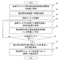
- FIG. 10 is a schematic operation flowchart showing an example of the operation at the time of calibration of the transmission circuit TC of the array antenna apparatus according to the present invention.
- mutual coupling amplitude phase information between the element antennas 100 is acquired in advance by a simulation by the measuring instrument 10 or a computer (step S1).
- the mutual coupling amplitude phase information 531 is recorded in the storage unit 530 of the transmission / reception control device 500 (step S2).
- the transmission / reception control unit 510 of the transmission / reception control device 500 selects an element antenna to be a reception antenna according to a schedule stored in advance in the storage unit 530 or an operator input from the IH 14 (step S3). Then, a calibration signal command CAS is sent to the signal transmitter 300 to generate a calibration signal, each transmission / reception module 200 is controlled, a signal is transmitted by switching the element antenna to be a transmission antenna, and the signal detector 420 receives the signal. (Step S4).
- the calibration signal calculation unit 520 uses the detection signal DS indicating the reception signal obtained by the signal detection unit 420 as the mutual coupling amplitude phase information stored in the storage unit 530 between the element antennas 100 that have transmitted and received signals. Correction is performed by dividing by the combined amplitude phase information (step S5). The correction is continued until correction is performed for all transmission antennas (step S6).
- the calibration signal calculation unit 520 calculates the variation between the elements of the corrected signal, and calculates the calibration value CV for the transmission circuit TC of each transmission antenna (step S7).
- the calibration value CV is composed of amplitude and phase values for compensating for variations in each corrected signal.
- the transmission / reception control unit 510 sets the amplitude and phase according to the calibration value CV in the transmission circuit TC of the transmission / reception module 200 of each transmission antenna (step S8).
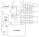
- FIG. 3 and 4 are diagrams schematically showing a configuration of an array antenna apparatus according to Embodiment 2 of the present invention.
- the transmission operation switching switch 213 and the reception operation switching switch 223 constituting the operation switching unit are used for switching the operations of the transmission circuit TC and the reception circuit RC in the transmission / reception module 200.
- a transmission variable attenuator 214 and a reception variable attenuator 224 may be used.
- the transmission / reception control unit 510 of the transmission / reception control device 500 can also switch the operation of the transmission circuit TC and the reception circuit RC by adjusting these attenuation amounts.
- a transmission variable amplifier 215 and a reception variable amplifier 225 may be used.
- the operation of the transmission circuit TC and the reception circuit RC can also be switched by adjusting the amplification factors of these amplifiers.
- FIG. FIG. 5 is a diagram schematically showing a configuration of an array antenna apparatus according to Embodiment 3 of the present invention.
- the connection between the transmission circuit TC and the reception circuit RC of the transmission / reception module 200 and the element antenna 100 is switched by the transmission / reception switching switch 231 that constitutes the transmission / reception switching unit.
- the transmission / reception switching switch 231 that constitutes the transmission / reception switching unit.
- a circulator 232 may be used instead of the changeover switch 231.
- the transmission circuit TC of the element antenna (E03) itself that receives the calibration signal is not a calibration target. That is, the transmission circuit TC in the connected transmission / reception module 200 cannot be transmitted and received by the reception circuit RC by one element antenna. Therefore, the circulator 232 is provided, and the transmission operation switching switch 213 and the reception operation switching switch 223 of the element antenna (E03) are set in the operation state, so that the signal transmitted by the element antenna (E03) ) Can be calibrated with the transmission circuit TC of another element antenna in the same manner as the procedure described in the first embodiment. The same applies to the receiving circuit RC. In this case, the self-coupled amplitude phase information about the space until the signal transmitted from the element antenna (E03) is received by the element antenna (E03) is the mutual coupling amplitude phase information.
- the present invention provides a plurality of element antennas (100), a transmission circuit (TC), a reception circuit (RC), and a transmission / reception switching unit (231-2) provided in each of the plurality of element antennas.
- a receiver (400) having a signal detector (420) for receiving the signal synthesized by the synthesizer and detecting the amplitude and phase of the received signal, and each transmission / reception according to a desired control signal (CS) Control of the amplitude and phase of the signal passing through the transmission circuit (TC) and the reception circuit (RC) of the module and switching of transmission / reception are performed to perform transmission / reception control, and at the time of calibration of the transmission / reception
- Each of the transceiver modules (200) includes an amplifying unit (211, 221) for amplifying a signal, a phase shifting unit (212, 222) for changing the phase, and an operation switching unit (213-5, 223-5) for switching operation / non-operation.
- the transmission / reception control device (500) performs transmission / reception control by controlling and switching the amplitude and phase of each transmission / reception module, and a storage unit (530) storing the mutual coupling amplitude / phase information.
- a calibration signal calculation unit (520) During calibration of the transmission / reception module, the transmission / reception control unit (510) operates the transmission circuit to transmit a signal to be received by the reception circuit, and the calibration signal calculation unit (520) is configured to transmit the signal detection unit (420).
- the transmission / reception control unit (510) determines the transmission circuit and the transmitter according to the calibration value.
- the operation switching units (213-5, 223-5) of the transmission / reception modules (200) include switching switches (213, 223). Further, each operation switching unit (213-5, 223-5) of each transmission / reception module (200) includes a variable attenuator (214, 224). The operation switching units (213-5, 223-5) of the transmission / reception modules (200) are variable amplifiers (215, 225). Each transmission / reception switching unit (231-2) includes a switching switch (231). Each transmission / reception switching unit (231-2) includes a circulator (232).
- the transmission / reception controller (510) operates one of the transmission circuits to transmit a signal, operates one of the reception circuits to receive a signal,
- the calibration signal calculation unit (520) uses the detection signal detected by the signal detection unit (420) and the corresponding mutual coupling amplitude phase information from the storage unit (530) as complex numbers, and converts the detection signal into the detection signal. The correction is performed by dividing by the mutual coupling amplitude phase information.
- the transmission / reception control unit (510) performs calibration between the plurality of transmission circuits by operating one of the reception circuits and transmitting a signal by sequentially operating the plurality of transmission circuits. .
- the transmission / reception control unit (510) performs calibration between the plurality of reception circuits by operating one of the transmission circuits and sequentially operating the plurality of reception circuits to receive signals.
- a transmission / reception module (200) having a transmission circuit (TC), a reception circuit (RC), and a transmission / reception switching unit (231-2) is connected to each of the plurality of element antennas (100).
- the signal transmitter (300) while controlling the amplitude and phase of the signal passing through the transmission circuit (TC) and the reception circuit (RC) of each transmission / reception module (200) and switching the transmission / reception.
- a signal to be transmitted from is distributed to each transmission circuit (TC) by a distributor (310) and transmitted, and a signal received from each reception circuit (RC) is synthesized by a synthesizer (410).
- a detection signal obtained by detecting the amplitude and phase of the signal received by the receiver (400) was obtained by correcting the mutual coupling amplitude phase information in the space between the element antennas. It consists of a calibration method for an array antenna apparatus that performs calibration according to calibration values.
- the present invention is not limited to the above embodiments, and includes all possible combinations thereof.
- the present invention can be applied to array antenna devices in various fields.
Landscapes
- Engineering & Computer Science (AREA)
- Computer Networks & Wireless Communication (AREA)
- Signal Processing (AREA)
- Physics & Mathematics (AREA)
- Electromagnetism (AREA)
- Radar, Positioning & Navigation (AREA)
- Remote Sensing (AREA)
- General Physics & Mathematics (AREA)
- Variable-Direction Aerials And Aerial Arrays (AREA)
- Radio Transmission System (AREA)
Abstract
Un dispositif d'antenne réseau, dans lequel des modules de transmission/réception comprenant chacun un circuit de transmission, un circuit de réception, et une unité de commutation de transmission/réception, sont connectés respectivement à une pluralité d'antennes d'élément, amène un distributeur à distribuer et à transmettre un signal à transmettre à partir d'un générateur de signaux aux circuits de transmission respectifs, amène un synthétiseur à synthétiser les signaux reçus en provenance des circuits de réception respectifs, et amène un récepteur à recevoir un signal synthétisé, tout en amenant un dispositif de commande de transmission/réception à effectuer une commande en commandant les amplitudes et les phases des signaux traversant les circuits de transmission et les circuits de réception des différents modules de transmission/réception et en commutant entre la transmission et la réception. Lorsque chacun des modules de transmission/réception est étalonné, l'étalonnage est effectué en fonction d'une valeur d'étalonnage obtenue par correction d'un signal de détection, obtenu en détectant l'amplitude et la phase du signal reçu par le récepteur, à l'aide d'informations d'amplitude/phase mutuellement couplées dans des espaces entre les antennes d'élément respectives.
Priority Applications (6)
| Application Number | Priority Date | Filing Date | Title |
|---|---|---|---|
| PCT/JP2016/055212 WO2017145257A1 (fr) | 2016-02-23 | 2016-02-23 | Dispositif d'antenne réseau et son procédé d'étalonnage |
| US16/076,787 US10355740B2 (en) | 2016-02-23 | 2017-02-21 | Array antenna device and calibration method therefor |
| JP2018501690A JP6775571B2 (ja) | 2016-02-23 | 2017-02-21 | アレーアンテナ装置およびその校正方法 |
| CN201780011739.4A CN108701899B (zh) | 2016-02-23 | 2017-02-21 | 阵列天线装置及其校正方法 |
| EP17756458.0A EP3422478B1 (fr) | 2016-02-23 | 2017-02-21 | Dispositif à antenne réseau et procédé d'étalonnage associé |
| PCT/JP2017/006293 WO2017146020A1 (fr) | 2016-02-23 | 2017-02-21 | Dispositif à antenne réseau et procédé d'étalonnage associé |
Applications Claiming Priority (1)
| Application Number | Priority Date | Filing Date | Title |
|---|---|---|---|
| PCT/JP2016/055212 WO2017145257A1 (fr) | 2016-02-23 | 2016-02-23 | Dispositif d'antenne réseau et son procédé d'étalonnage |
Publications (1)
| Publication Number | Publication Date |
|---|---|
| WO2017145257A1 true WO2017145257A1 (fr) | 2017-08-31 |
Family
ID=59685968
Family Applications (2)
| Application Number | Title | Priority Date | Filing Date |
|---|---|---|---|
| PCT/JP2016/055212 Ceased WO2017145257A1 (fr) | 2016-02-23 | 2016-02-23 | Dispositif d'antenne réseau et son procédé d'étalonnage |
| PCT/JP2017/006293 Ceased WO2017146020A1 (fr) | 2016-02-23 | 2017-02-21 | Dispositif à antenne réseau et procédé d'étalonnage associé |
Family Applications After (1)
| Application Number | Title | Priority Date | Filing Date |
|---|---|---|---|
| PCT/JP2017/006293 Ceased WO2017146020A1 (fr) | 2016-02-23 | 2017-02-21 | Dispositif à antenne réseau et procédé d'étalonnage associé |
Country Status (5)
| Country | Link |
|---|---|
| US (1) | US10355740B2 (fr) |
| EP (1) | EP3422478B1 (fr) |
| JP (1) | JP6775571B2 (fr) |
| CN (1) | CN108701899B (fr) |
| WO (2) | WO2017145257A1 (fr) |
Cited By (1)
| Publication number | Priority date | Publication date | Assignee | Title |
|---|---|---|---|---|
| CN107390192A (zh) * | 2017-09-20 | 2017-11-24 | 雷象科技(北京)有限公司 | 相控阵天气雷达快速幅度、相位一致性测量方法 |
Families Citing this family (15)
| Publication number | Priority date | Publication date | Assignee | Title |
|---|---|---|---|---|
| CN106685495A (zh) * | 2015-11-05 | 2017-05-17 | 索尼公司 | 无线通信方法和无线通信设备 |
| DE102016212136A1 (de) * | 2016-07-04 | 2018-01-04 | Laird Bochum GmbH | Verfahren und Vorrichtung zur Bestimmung einer Distanz sowie Fahrzeug |
| EP3553885B1 (fr) * | 2016-12-29 | 2023-03-01 | Huawei Technologies Co., Ltd. | Antenne réseau et appareil de réseau |
| JP7124360B2 (ja) * | 2018-03-14 | 2022-08-24 | 日本電気株式会社 | 装置、装置による制御方法及びプログラム |
| JP2020016572A (ja) * | 2018-07-26 | 2020-01-30 | 日立オートモティブシステムズ株式会社 | レーダセンサ |
| CN109946662B (zh) * | 2019-05-06 | 2023-09-26 | 成都远望科技有限责任公司 | 一种相控阵天气雷达机内标校系统 |
| KR102060120B1 (ko) * | 2019-07-09 | 2019-12-27 | 국방과학연구소 | 능동 위상배열 안테나 장치 및 이의 송신채널 점검 방법 |
| KR102883635B1 (ko) * | 2019-10-11 | 2025-11-07 | 레오랩스, 인크. | 레이더 보정 및 우주 물체 추적 |
| JP7012918B2 (ja) * | 2019-12-10 | 2022-02-14 | 三菱電機株式会社 | アンテナ装置及び校正方法 |
| CN114640404A (zh) * | 2020-12-16 | 2022-06-17 | 深圳市中兴微电子技术有限公司 | 一种幅度相位校准方法、装置、存储介质及电子装置 |
| CN113824512B (zh) * | 2021-09-13 | 2023-10-10 | 中信科移动通信技术股份有限公司 | 大规模天线调测方法、测试设备及计算机设备 |
| TWI796828B (zh) * | 2021-11-10 | 2023-03-21 | 財團法人工業技術研究院 | 天線陣列校正裝置與其方法 |
| CN116418376A (zh) * | 2021-12-29 | 2023-07-11 | 中兴通讯股份有限公司 | 天线解耦方法、电子设备和计算机可读存储介质 |
| US12542584B2 (en) * | 2023-11-01 | 2026-02-03 | Novatel Inc. | Systems, methods, and media for estimating an auto-correlation matrix for a transceiver |
| EP4576616A1 (fr) * | 2023-11-01 | 2025-06-25 | Novatel, Inc. | Systèmes et procédés pour estimer une matrice d'auto-corrélation pour un émetteur-récepteur |
Citations (3)
| Publication number | Priority date | Publication date | Assignee | Title |
|---|---|---|---|---|
| JPH09148836A (ja) * | 1995-11-21 | 1997-06-06 | Mitsubishi Electric Corp | アンテナ装置 |
| JP2010034937A (ja) * | 2008-07-30 | 2010-02-12 | Sony Corp | 無線通信装置及び無線通信方法、並びにコンピューター・プログラム |
| JP2014505392A (ja) * | 2010-12-01 | 2014-02-27 | テレフオンアクチーボラゲット エル エム エリクソン(パブル) | 少なくとも1つのキャリブレーションパラメータを取得するための方法、及び、アンテナアレイ |
Family Cites Families (14)
| Publication number | Priority date | Publication date | Assignee | Title |
|---|---|---|---|---|
| US6208287B1 (en) * | 1998-03-16 | 2001-03-27 | Raytheoncompany | Phased array antenna calibration system and method |
| ID27970A (id) * | 1998-08-05 | 2001-05-03 | Sanyo Electric Co | Radas radio dan metode kalibrasi untuk itu |
| JP2002135187A (ja) * | 2000-10-24 | 2002-05-10 | Sony Corp | 受信機 |
| KR100913883B1 (ko) * | 2002-04-19 | 2009-08-26 | 삼성전자주식회사 | 스마트 안테나의 출력 신호 왜곡 측정 및 보상 장치 및 방법 |
| US7031669B2 (en) * | 2002-09-10 | 2006-04-18 | Cognio, Inc. | Techniques for correcting for phase and amplitude offsets in a MIMO radio device |
| CN1176555C (zh) * | 2002-12-25 | 2004-11-17 | 大唐移动通信设备有限公司 | 一种对智能天线阵系统进行实时校准的方法 |
| JP4478606B2 (ja) | 2005-05-19 | 2010-06-09 | 富士通株式会社 | リニアアレイアンテナの校正装置及び校正方法 |
| US8754811B1 (en) * | 2011-04-08 | 2014-06-17 | Lockheed Martin Corporation | Digital beamforming phased array |
| CN102594426B (zh) * | 2012-02-21 | 2014-09-10 | 中兴通讯股份有限公司 | 一种有源天线多收发通道同步校准的装置和方法 |
| US9094254B2 (en) * | 2012-11-15 | 2015-07-28 | Telefonaktiebolaget L M Ericsson (Publ) | Method and apparatus for antenna array calibration using traffic signals |
| US9300408B2 (en) * | 2013-11-04 | 2016-03-29 | Alcatel-Lucent Shanghai Bell Co., Ltd | Methods and systems for calibrating LTE antenna systems |
| US9866336B2 (en) * | 2015-06-17 | 2018-01-09 | Google Llc | Phased array antenna self-calibration |
| US10103431B2 (en) * | 2016-04-21 | 2018-10-16 | Google Llc | Phased array antenna calibration |
| US10128894B1 (en) * | 2017-05-09 | 2018-11-13 | Analog Devices Global | Active antenna calibration |
-
2016
- 2016-02-23 WO PCT/JP2016/055212 patent/WO2017145257A1/fr not_active Ceased
-
2017
- 2017-02-21 JP JP2018501690A patent/JP6775571B2/ja active Active
- 2017-02-21 US US16/076,787 patent/US10355740B2/en active Active
- 2017-02-21 EP EP17756458.0A patent/EP3422478B1/fr active Active
- 2017-02-21 WO PCT/JP2017/006293 patent/WO2017146020A1/fr not_active Ceased
- 2017-02-21 CN CN201780011739.4A patent/CN108701899B/zh active Active
Patent Citations (3)
| Publication number | Priority date | Publication date | Assignee | Title |
|---|---|---|---|---|
| JPH09148836A (ja) * | 1995-11-21 | 1997-06-06 | Mitsubishi Electric Corp | アンテナ装置 |
| JP2010034937A (ja) * | 2008-07-30 | 2010-02-12 | Sony Corp | 無線通信装置及び無線通信方法、並びにコンピューター・プログラム |
| JP2014505392A (ja) * | 2010-12-01 | 2014-02-27 | テレフオンアクチーボラゲット エル エム エリクソン(パブル) | 少なくとも1つのキャリブレーションパラメータを取得するための方法、及び、アンテナアレイ |
Cited By (2)
| Publication number | Priority date | Publication date | Assignee | Title |
|---|---|---|---|---|
| CN107390192A (zh) * | 2017-09-20 | 2017-11-24 | 雷象科技(北京)有限公司 | 相控阵天气雷达快速幅度、相位一致性测量方法 |
| CN107390192B (zh) * | 2017-09-20 | 2020-04-10 | 雷象科技(北京)有限公司 | 相控阵天气雷达快速幅度、相位一致性测量方法 |
Also Published As
| Publication number | Publication date |
|---|---|
| US20190044568A1 (en) | 2019-02-07 |
| WO2017146020A1 (fr) | 2017-08-31 |
| US10355740B2 (en) | 2019-07-16 |
| CN108701899A (zh) | 2018-10-23 |
| EP3422478B1 (fr) | 2022-09-07 |
| CN108701899B (zh) | 2021-08-13 |
| JPWO2017146020A1 (ja) | 2018-12-20 |
| JP6775571B2 (ja) | 2020-10-28 |
| EP3422478A1 (fr) | 2019-01-02 |
| EP3422478A4 (fr) | 2019-10-09 |
Similar Documents
| Publication | Publication Date | Title |
|---|---|---|
| WO2017145257A1 (fr) | Dispositif d'antenne réseau et son procédé d'étalonnage | |
| US6133868A (en) | System and method for fully self-contained calibration of an antenna array | |
| US11973473B2 (en) | Phased array amplifier linearization | |
| KR100613740B1 (ko) | 페이즈드 어레이 안테나 교정 시스템 및 방법 | |
| EP0981836B1 (fr) | Procede et dispositif de calage d'antenne | |
| EP2273614A1 (fr) | Procédé et appareil pour le ré-étalonnage du champ d'une antenne de réseau phasé | |
| US6778147B2 (en) | Antenna apparatus | |
| KR101389837B1 (ko) | 커플링 라인을 이용한 레이더 시스템의 배열 안테나 보정 장치 및 그 방법 | |
| JP6234360B2 (ja) | アレイアンテナ装置及び校正方法 | |
| JP7012918B2 (ja) | アンテナ装置及び校正方法 | |
| KR102827818B1 (ko) | 위상배열 송수신 시스템의 위상 보정 제어 방법 및 그를 위한 장치 | |
| JP2017005647A (ja) | 位相制御装置及びアレーアンテナシステム | |
| JP4521440B2 (ja) | アレイアンテナ装置及びその送受信モジュール | |
| JPH11225014A (ja) | フェーズドアレイレーダ装置及びその位相校正方法 | |
| KR20200139001A (ko) | 모노펄스 시스템 및 이의 에러 각도 도출 방법 | |
| JP4121082B2 (ja) | アンテナ診断装置 | |
| JP2002246825A (ja) | アレーアンテナ装置 | |
| JPH0627800B2 (ja) | アンテナモジュール | |
| JP2023142491A (ja) | 無線通信装置及びキャリブレーション方法 | |
| JP2006093871A (ja) | アレイアンテナ受信装置、アレイアンテナ送信装置、アレイアンテナ通信装置及び校正方法 | |
| JPH01227977A (ja) | フェーズドアレイレーダ装置 | |
| WO2019221130A1 (fr) | Dispositif de communication en réseau et procédé de commande de celui-ci |
Legal Events
| Date | Code | Title | Description |
|---|---|---|---|
| NENP | Non-entry into the national phase |
Ref country code: DE |
|
| 121 | Ep: the epo has been informed by wipo that ep was designated in this application |
Ref document number: 16891416 Country of ref document: EP Kind code of ref document: A1 |
|
| 122 | Ep: pct application non-entry in european phase |
Ref document number: 16891416 Country of ref document: EP Kind code of ref document: A1 |
|
| NENP | Non-entry into the national phase |
Ref country code: JP |