WO2017145295A1 - Dispositif de mesure et testeur de matériau - Google Patents
Dispositif de mesure et testeur de matériau Download PDFInfo
- Publication number
- WO2017145295A1 WO2017145295A1 PCT/JP2016/055472 JP2016055472W WO2017145295A1 WO 2017145295 A1 WO2017145295 A1 WO 2017145295A1 JP 2016055472 W JP2016055472 W JP 2016055472W WO 2017145295 A1 WO2017145295 A1 WO 2017145295A1
- Authority
- WO
- WIPO (PCT)
- Prior art keywords
- detector
- amplifier
- calibration
- cable unit
- gain
- Prior art date
- Legal status (The legal status is an assumption and is not a legal conclusion. Google has not performed a legal analysis and makes no representation as to the accuracy of the status listed.)
- Ceased
Links
Images




Classifications
-
- G—PHYSICS
- G01—MEASURING; TESTING
- G01N—INVESTIGATING OR ANALYSING MATERIALS BY DETERMINING THEIR CHEMICAL OR PHYSICAL PROPERTIES
- G01N3/00—Investigating strength properties of solid materials by application of mechanical stress
- G01N3/02—Details
- G01N3/06—Special adaptations of indicating or recording means
- G01N3/066—Special adaptations of indicating or recording means with electrical indicating or recording means
-
- G—PHYSICS
- G01—MEASURING; TESTING
- G01N—INVESTIGATING OR ANALYSING MATERIALS BY DETERMINING THEIR CHEMICAL OR PHYSICAL PROPERTIES
- G01N3/00—Investigating strength properties of solid materials by application of mechanical stress
- G01N3/08—Investigating strength properties of solid materials by application of mechanical stress by applying steady tensile or compressive forces
-
- G—PHYSICS
- G01—MEASURING; TESTING
- G01N—INVESTIGATING OR ANALYSING MATERIALS BY DETERMINING THEIR CHEMICAL OR PHYSICAL PROPERTIES
- G01N3/00—Investigating strength properties of solid materials by application of mechanical stress
- G01N3/02—Details
- G01N3/06—Special adaptations of indicating or recording means
-
- G—PHYSICS
- G01—MEASURING; TESTING
- G01N—INVESTIGATING OR ANALYSING MATERIALS BY DETERMINING THEIR CHEMICAL OR PHYSICAL PROPERTIES
- G01N3/00—Investigating strength properties of solid materials by application of mechanical stress
- G01N3/62—Manufacturing, calibrating, or repairing devices used in investigations covered by the preceding subgroups
-
- H—ELECTRICITY
- H03—ELECTRONIC CIRCUITRY
- H03F—AMPLIFIERS
- H03F3/00—Amplifiers with only discharge tubes or only semiconductor devices as amplifying elements
- H03F3/45—Differential amplifiers
-
- G—PHYSICS
- G01—MEASURING; TESTING
- G01B—MEASURING LENGTH, THICKNESS OR SIMILAR LINEAR DIMENSIONS; MEASURING ANGLES; MEASURING AREAS; MEASURING IRREGULARITIES OF SURFACES OR CONTOURS
- G01B7/00—Measuring arrangements characterised by the use of electric or magnetic techniques
- G01B7/16—Measuring arrangements characterised by the use of electric or magnetic techniques for measuring the deformation in a solid, e.g. by resistance strain gauge
-
- H—ELECTRICITY
- H03—ELECTRONIC CIRCUITRY
- H03F—AMPLIFIERS
- H03F2200/00—Indexing scheme relating to amplifiers
- H03F2200/261—Amplifier which being suitable for instrumentation applications
Definitions
- the cable unit in the measurement apparatus according to the first aspect, includes an electrical calibration circuit having a calibration bridge and a calibration resistor, and a detector to the instrumentation amplifier. And a switch for switching the connection state between the electrical calibration circuit and the instrumentation amplifier.
- the electrical calibration circuit is provided in the cable unit, so-called shunt calibration can be executed regardless of which detector is connected. . That is, by providing an electrical calibration circuit in the cable unit, it is possible to perform electrical calibration even for detectors that could not be electrically calibrated conventionally. Furthermore, since the input from the detector side can be disconnected by the switch, it is not necessary to confirm the stationary state on the detector side as in the prior art when performing electrical calibration. For this reason, electrical calibration can be performed regardless of the state on the detector side. Therefore, the gain on the sensor amplifier side can be accurately adjusted.
- test force data and displacement amount data from the load cell 14 and the displacement meter 15 are taken in, and data processing is executed by the CPU. Further, in the control panel 40, feedback control of the rotational drive of the servo motor 31 is executed by using the test force and the displacement amount inputted as digital data by the operation of the control program stored in the digital circuit or ROM. Is done.
- the displacement meter 15, the cable unit 24, and the sensor amplifier 42 constitute a displacement measuring system for the test piece 10 and function as the measuring device of the present invention.
- the displacement meter 15 and the cable unit 24 can be detached from the tester main body 1.
- the load cell 14, the cable unit 24, and the sensor amplifier 41 constitute a test force measuring system applied to the test piece 10, and functions as a measuring apparatus of the present invention.
- the load cell 14 and the cable unit 24 can be detached from the tester main body 1.
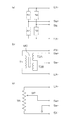
- the displacement meter 15 includes a strain gauge displacement meter, a differential transformer displacement meter, and a potentiometer displacement meter depending on the measurement method, and is selected according to the content of the test. Similar to the load cell 14, the strain gauge displacement meter includes a bridge circuit shown in FIG. As shown in FIG. 3B, the differential transformer displacement meter includes a primary coil T1, secondary coils T2A and T2B, and an iron core MC that moves in conjunction with the elongation of the test piece 10. A voltage output corresponding to the displacement is obtained by utilizing a difference depending on the position of the iron core MC between the induced voltage of the secondary coil T2A and the secondary coil T2B generated when the coil T1 is excited. It is a detector. As shown in FIG.
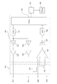
- the sensor amplifier-side connector 242 of the cable unit 24 When the sensor amplifier-side connector 242 of the cable unit 24 is connected to the sensor amplifier 42, information such as the detector type stored in the nonvolatile memory 25 of the substrate 244 is read into the FPGA 60.
- the cable unit 24 and the detector are used as a pair, and the resistance value of the gain resistor 26 is previously set so as to be an optimum size for the analog circuit in the sensor amplifier 42 according to the detector. It is a fixed value.
- the value of the indicator 48 at this time is the value indicated by the indicator 48 stored in the nonvolatile memory 25 in the calibration by the actual displacement, that is, the indicator 48 indicated when a load corresponding to the rated capacity is applied.
- the value multiplied by the gain multiplier 69 of the FPGA 60 is adjusted so as to match the value.
- the switches S3 to S6 are opened, and the switches S1 and S2 are closed. Then, the value subtracted from the signal input from the detection circuit 61 held at this time by the offset subtracter 68 is written back to the value (offset value) previously stored in the nonvolatile memory 25. Thereby, the electrical calibration by the shunt resistor is completed.
- the nonvolatile memory 25 of the cable unit 24 can store information necessary for identification of the detector, such as the type and specification of the detector.
- the gain resistor 26 of the cable unit 24 has the type of detector and the full scale. Therefore, the cable unit 24 can be used for any strain gauge type load cell, strain gauge type displacement meter, differential transformer type displacement meter, or potentiometer type displacement meter. Thus, it can be connected to the sensor amplifier, and the accuracy and resolution on the sensor amplifier side can be improved.
Landscapes
- Physics & Mathematics (AREA)
- Health & Medical Sciences (AREA)
- Life Sciences & Earth Sciences (AREA)
- Chemical & Material Sciences (AREA)
- Analytical Chemistry (AREA)
- Biochemistry (AREA)
- General Health & Medical Sciences (AREA)
- General Physics & Mathematics (AREA)
- Immunology (AREA)
- Pathology (AREA)
- Engineering & Computer Science (AREA)
- Power Engineering (AREA)
- Manufacturing & Machinery (AREA)
- Investigating Strength Of Materials By Application Of Mechanical Stress (AREA)
Abstract
Priority Applications (4)
| Application Number | Priority Date | Filing Date | Title |
|---|---|---|---|
| EP16891452.1A EP3421966B1 (fr) | 2016-02-24 | 2016-02-24 | Dispositif de mesure et testeur de matériau |
| PCT/JP2016/055472 WO2017145295A1 (fr) | 2016-02-24 | 2016-02-24 | Dispositif de mesure et testeur de matériau |
| US16/061,837 US10697872B2 (en) | 2016-02-24 | 2016-02-24 | Measurement device and material tester |
| JP2018501476A JP6477969B2 (ja) | 2016-02-24 | 2016-02-24 | 測定装置および材料試験機 |
Applications Claiming Priority (1)
| Application Number | Priority Date | Filing Date | Title |
|---|---|---|---|
| PCT/JP2016/055472 WO2017145295A1 (fr) | 2016-02-24 | 2016-02-24 | Dispositif de mesure et testeur de matériau |
Publications (1)
| Publication Number | Publication Date |
|---|---|
| WO2017145295A1 true WO2017145295A1 (fr) | 2017-08-31 |
Family
ID=59684894
Family Applications (1)
| Application Number | Title | Priority Date | Filing Date |
|---|---|---|---|
| PCT/JP2016/055472 Ceased WO2017145295A1 (fr) | 2016-02-24 | 2016-02-24 | Dispositif de mesure et testeur de matériau |
Country Status (4)
| Country | Link |
|---|---|
| US (1) | US10697872B2 (fr) |
| EP (1) | EP3421966B1 (fr) |
| JP (1) | JP6477969B2 (fr) |
| WO (1) | WO2017145295A1 (fr) |
Families Citing this family (3)
| Publication number | Priority date | Publication date | Assignee | Title |
|---|---|---|---|---|
| US10962623B1 (en) * | 2017-05-17 | 2021-03-30 | Heathkit Company, Inc. | Accurate and model-based measurement and management systems and methods |
| JP7472505B2 (ja) * | 2020-01-24 | 2024-04-23 | 株式会社島津製作所 | 材料試験機、及び材料試験機の制御方法 |
| CN114878335B (zh) * | 2022-07-11 | 2022-09-30 | 杭州应敏科技有限公司 | 一种电缆抗拉强度试验装置 |
Citations (6)
| Publication number | Priority date | Publication date | Assignee | Title |
|---|---|---|---|---|
| JPS6178076A (ja) * | 1984-09-25 | 1986-04-21 | 松下電工株式会社 | 信号線の接続構造 |
| JPH0333336U (fr) * | 1989-08-09 | 1991-04-02 | ||
| JPH08247863A (ja) * | 1995-03-10 | 1996-09-27 | A & D Co Ltd | ロードセル及び材料試験機 |
| JP2007078560A (ja) * | 2005-09-15 | 2007-03-29 | Shimadzu Corp | 材料試験機の制御装置 |
| JP2011169774A (ja) * | 2010-02-19 | 2011-09-01 | Shimadzu Corp | 変位計用アンプ装置 |
| JP4957645B2 (ja) * | 2008-05-12 | 2012-06-20 | 株式会社島津製作所 | 材料試験機 |
Family Cites Families (8)
| Publication number | Priority date | Publication date | Assignee | Title |
|---|---|---|---|---|
| US5606515A (en) * | 1993-02-03 | 1997-02-25 | Instron Corporation | Sensor conditioning circuitry for use with electrically excited transducers |
| EP0897110A3 (fr) * | 1997-08-13 | 2000-01-12 | Japan Tobacco Inc. | Dispositif d'essai de matériaux |
| JP4697433B2 (ja) | 2006-02-17 | 2011-06-08 | 株式会社島津製作所 | 材料試験機 |
| JP2009250678A (ja) * | 2008-04-02 | 2009-10-29 | Shimadzu Corp | 材料試験機 |
| JP6094463B2 (ja) * | 2013-12-09 | 2017-03-15 | 株式会社島津製作所 | 材料試験機 |
| US10168371B2 (en) * | 2017-04-04 | 2019-01-01 | Pa&E, Hermetic Solutions Group, Llc | System and methods for determining the impact of moisture on dielectric sealing material of downhole electrical feedthrough packages |
| WO2019070659A1 (fr) * | 2017-10-03 | 2019-04-11 | Waters Technologies Corporation | Estimation et correction de conformité de système automatique pour systèmes de test mécanique |
| AU2019215098A1 (en) * | 2018-02-05 | 2020-08-27 | Advanced Solutions Life Sciences, Llc | System and workstation for the design, fabrication and assembly of 3-dimensional constructs |
-
2016
- 2016-02-24 JP JP2018501476A patent/JP6477969B2/ja active Active
- 2016-02-24 US US16/061,837 patent/US10697872B2/en active Active
- 2016-02-24 EP EP16891452.1A patent/EP3421966B1/fr active Active
- 2016-02-24 WO PCT/JP2016/055472 patent/WO2017145295A1/fr not_active Ceased
Patent Citations (6)
| Publication number | Priority date | Publication date | Assignee | Title |
|---|---|---|---|---|
| JPS6178076A (ja) * | 1984-09-25 | 1986-04-21 | 松下電工株式会社 | 信号線の接続構造 |
| JPH0333336U (fr) * | 1989-08-09 | 1991-04-02 | ||
| JPH08247863A (ja) * | 1995-03-10 | 1996-09-27 | A & D Co Ltd | ロードセル及び材料試験機 |
| JP2007078560A (ja) * | 2005-09-15 | 2007-03-29 | Shimadzu Corp | 材料試験機の制御装置 |
| JP4957645B2 (ja) * | 2008-05-12 | 2012-06-20 | 株式会社島津製作所 | 材料試験機 |
| JP2011169774A (ja) * | 2010-02-19 | 2011-09-01 | Shimadzu Corp | 変位計用アンプ装置 |
Also Published As
| Publication number | Publication date |
|---|---|
| JPWO2017145295A1 (ja) | 2018-07-12 |
| US20180372602A1 (en) | 2018-12-27 |
| EP3421966A1 (fr) | 2019-01-02 |
| EP3421966B1 (fr) | 2020-11-25 |
| EP3421966A4 (fr) | 2019-09-04 |
| US10697872B2 (en) | 2020-06-30 |
| JP6477969B2 (ja) | 2019-03-06 |
Similar Documents
| Publication | Publication Date | Title |
|---|---|---|
| US3847017A (en) | Strain measuring system | |
| CN206057424U (zh) | 一种电流测量装置 | |
| CN106405460A (zh) | 电子仪表电压检测校准系统及校准方法 | |
| JP6477969B2 (ja) | 測定装置および材料試験機 | |
| EP4459295A1 (fr) | Capteur de courant à auto-étalonnage | |
| JP6947803B2 (ja) | 過負荷診断付き天秤 | |
| JP2020109402A5 (fr) | ||
| RU2417349C1 (ru) | Способ измерения относительных деформаций конструкций многоточечной тензометрической измерительной системой | |
| JP6516063B2 (ja) | 測定装置および材料試験機 | |
| JP2003315372A (ja) | 電流測定装置 | |
| JP2009250678A (ja) | 材料試験機 | |
| JP2923293B1 (ja) | ひずみ測定方法 | |
| JP2019207192A (ja) | 材料試験機 | |
| CN103154674B (zh) | 校准检测系统和方法 | |
| JP5240216B2 (ja) | 変位計用アンプ装置 | |
| JP2007132897A (ja) | 測定装置 | |
| JP2000235053A (ja) | 計測装置 | |
| JP5203798B2 (ja) | エアマイクロメーター | |
| JP2011169765A (ja) | アクティブ4ゲージ法を用いた測定装置の校正方法および測定装置並びに材料試験機 | |
| JP2007240378A (ja) | ひずみ・温度測定方法 | |
| CN115792765A (zh) | 一种动态信号测试分析系统的校准方法 | |
| JP5488329B2 (ja) | 材料試験機 | |
| JP3848661B2 (ja) | ひずみ測定方法及び多点ひずみ測定システム | |
| JP2923294B1 (ja) | ひずみ測定方法 | |
| JP5717344B2 (ja) | 測定装置および測定方法 |
Legal Events
| Date | Code | Title | Description |
|---|---|---|---|
| ENP | Entry into the national phase |
Ref document number: 2018501476 Country of ref document: JP Kind code of ref document: A |
|
| NENP | Non-entry into the national phase |
Ref country code: DE |
|
| WWE | Wipo information: entry into national phase |
Ref document number: 2016891452 Country of ref document: EP |
|
| ENP | Entry into the national phase |
Ref document number: 2016891452 Country of ref document: EP Effective date: 20180924 |
|
| 121 | Ep: the epo has been informed by wipo that ep was designated in this application |
Ref document number: 16891452 Country of ref document: EP Kind code of ref document: A1 |