WO2017145349A1 - Système de commande de bras de robot - Google Patents
Système de commande de bras de robot Download PDFInfo
- Publication number
- WO2017145349A1 WO2017145349A1 PCT/JP2016/055767 JP2016055767W WO2017145349A1 WO 2017145349 A1 WO2017145349 A1 WO 2017145349A1 JP 2016055767 W JP2016055767 W JP 2016055767W WO 2017145349 A1 WO2017145349 A1 WO 2017145349A1
- Authority
- WO
- WIPO (PCT)
- Prior art keywords
- jig plate
- workpiece
- robot arm
- screw
- work
- Prior art date
- Legal status (The legal status is an assumption and is not a legal conclusion. Google has not performed a legal analysis and makes no representation as to the accuracy of the status listed.)
- Ceased
Links
Images



Classifications
-
- B—PERFORMING OPERATIONS; TRANSPORTING
- B23—MACHINE TOOLS; METAL-WORKING NOT OTHERWISE PROVIDED FOR
- B23P—METAL-WORKING NOT OTHERWISE PROVIDED FOR; COMBINED OPERATIONS; UNIVERSAL MACHINE TOOLS
- B23P19/00—Machines for simply fitting together or separating metal parts or objects, or metal and non-metal parts, whether or not involving some deformation; Tools or devices therefor so far as not provided for in other classes
- B23P19/04—Machines for simply fitting together or separating metal parts or objects, or metal and non-metal parts, whether or not involving some deformation; Tools or devices therefor so far as not provided for in other classes for assembling or disassembling parts
-
- B—PERFORMING OPERATIONS; TRANSPORTING
- B23—MACHINE TOOLS; METAL-WORKING NOT OTHERWISE PROVIDED FOR
- B23P—METAL-WORKING NOT OTHERWISE PROVIDED FOR; COMBINED OPERATIONS; UNIVERSAL MACHINE TOOLS
- B23P19/00—Machines for simply fitting together or separating metal parts or objects, or metal and non-metal parts, whether or not involving some deformation; Tools or devices therefor so far as not provided for in other classes
- B23P19/04—Machines for simply fitting together or separating metal parts or objects, or metal and non-metal parts, whether or not involving some deformation; Tools or devices therefor so far as not provided for in other classes for assembling or disassembling parts
- B23P19/06—Screw or nut setting or loosening machines
-
- B—PERFORMING OPERATIONS; TRANSPORTING
- B23—MACHINE TOOLS; METAL-WORKING NOT OTHERWISE PROVIDED FOR
- B23P—METAL-WORKING NOT OTHERWISE PROVIDED FOR; COMBINED OPERATIONS; UNIVERSAL MACHINE TOOLS
- B23P19/00—Machines for simply fitting together or separating metal parts or objects, or metal and non-metal parts, whether or not involving some deformation; Tools or devices therefor so far as not provided for in other classes
- B23P19/10—Aligning parts to be fitted together
-
- B—PERFORMING OPERATIONS; TRANSPORTING
- B23—MACHINE TOOLS; METAL-WORKING NOT OTHERWISE PROVIDED FOR
- B23P—METAL-WORKING NOT OTHERWISE PROVIDED FOR; COMBINED OPERATIONS; UNIVERSAL MACHINE TOOLS
- B23P19/00—Machines for simply fitting together or separating metal parts or objects, or metal and non-metal parts, whether or not involving some deformation; Tools or devices therefor so far as not provided for in other classes
- B23P19/10—Aligning parts to be fitted together
- B23P19/12—Alignment of parts for insertion into bores
-
- B—PERFORMING OPERATIONS; TRANSPORTING
- B25—HAND TOOLS; PORTABLE POWER-DRIVEN TOOLS; MANIPULATORS
- B25J—MANIPULATORS; CHAMBERS PROVIDED WITH MANIPULATION DEVICES
- B25J13/00—Controls for manipulators
-
- B—PERFORMING OPERATIONS; TRANSPORTING
- B25—HAND TOOLS; PORTABLE POWER-DRIVEN TOOLS; MANIPULATORS
- B25J—MANIPULATORS; CHAMBERS PROVIDED WITH MANIPULATION DEVICES
- B25J19/00—Accessories fitted to manipulators, e.g. for monitoring, for viewing; Safety devices combined with or specially adapted for use in connection with manipulators
- B25J19/02—Sensing devices
-
- B—PERFORMING OPERATIONS; TRANSPORTING
- B25—HAND TOOLS; PORTABLE POWER-DRIVEN TOOLS; MANIPULATORS
- B25J—MANIPULATORS; CHAMBERS PROVIDED WITH MANIPULATION DEVICES
- B25J9/00—Program-controlled manipulators
- B25J9/16—Program controls
- B25J9/1679—Program controls characterised by the tasks executed
- B25J9/1682—Dual arm manipulator; Coordination of several manipulators
-
- B—PERFORMING OPERATIONS; TRANSPORTING
- B25—HAND TOOLS; PORTABLE POWER-DRIVEN TOOLS; MANIPULATORS
- B25J—MANIPULATORS; CHAMBERS PROVIDED WITH MANIPULATION DEVICES
- B25J9/00—Program-controlled manipulators
- B25J9/16—Program controls
- B25J9/1679—Program controls characterised by the tasks executed
- B25J9/1687—Assembly, peg and hole, palletising, straight line, weaving pattern movement
-
- G—PHYSICS
- G05—CONTROLLING; REGULATING
- G05B—CONTROL OR REGULATING SYSTEMS IN GENERAL; FUNCTIONAL ELEMENTS OF SUCH SYSTEMS; MONITORING OR TESTING ARRANGEMENTS FOR SUCH SYSTEMS OR ELEMENTS
- G05B2219/00—Program-control systems
- G05B2219/30—Nc systems
- G05B2219/39—Robotics, robotics to robotics hand
- G05B2219/39129—One manipulator holds one piece, other inserts, screws other piece, dexterity
Definitions
- the present invention relates to a robot arm control system.
- Patent Document 1 discloses an automatic screw tightening device that manufactures a liquid crystal module in which a frame-like bezel is fixed to a backlight unit of a liquid crystal panel with screws. Specifically, when the liquid crystal module before being screwed is conveyed from the previous process to the front of the automatic screwing device on the conveyor, the control unit of the automatic screwing device recognizes the position of the screw hole of the bezel, The screw tightening unit is controlled to automatically tighten the bezel.
- the present invention has been made in order to solve the above-described problems, and has as its main purpose to improve work efficiency when working with a variety of workpieces pressed by a jig plate.
- the robot arm control system of the present invention is First and second robot arms that perform work on a workpiece having a portion to be inserted at a predetermined position; Information reading means for reading information on the type of workpiece attached to the workpiece or the container on which the workpiece is placed; Jig plate accommodating means for accommodating a plurality of types of jig plates; Storage means for storing the correspondence between the workpiece type and the jig plate type; Control means for controlling the first and second robot arms; With The control means includes The first robot arm takes out a jig plate corresponding to the work type read by the information reading means from the jig plate accommodating means, and the position of the guide hole provided in the jig plate indicates the inserted portion of the work.
- the first robot arm is controlled so that the jig plate is placed on the workpiece so as to match the position and the workpiece is pressed by the jig plate.
- the second robot arm controls the second robot arm so that an insertion tool is inserted into the insertion portion using the guide hole of the jig plate pressing the workpiece.
- the first robot arm takes out the jig plate corresponding to the workpiece type from the jig plate accommodating means so that the position of the guide hole provided in the jig plate matches the position of the inserted portion of the workpiece. Place the jig plate on the workpiece and press the workpiece with the jig plate. Further, the second robot arm puts the insertion tool into the insertion portion using the guide hole of the jig plate that holds the workpiece. Therefore, even if there are many types of workpieces, the jig plate corresponding to the workpiece type can be automatically taken out.
- the workpiece can be prevented from being lifted by pressing the workpiece with a jig plate that matches the workpiece. Therefore, the work efficiency when working with holding various types of workpieces with the jig plate is increased.
- the control means controls the first robot arm
- the work type in which the current jig plate type held by the first robot arm is read by the information reading means.
- the first robot arm is controlled so that the jig plate corresponding to the workpiece type is taken out from the jig plate accommodating means after the current jig plate is returned to the jig plate accommodating means. May be. If it carries out like this, it can replace
- the workpiece includes a first member having a first fastening hole and a second member having a second fastening hole, and the second fastening hole is disposed immediately above the first fastening hole.
- the jig plate in which the second robot arm presses the work piece, and the control unit is a laminated body stacked so as to constitute the inserted portion.
- the second robot arm is configured to guide the fastener to the second fastening hole and the first fastening hole using the guide hole and to fasten the second member and the first member with the fastener. May be controlled. If it carries out like this, both can be fastened with a fastener in the state which piled up the 2nd member on the 1st member.
- the fastener is a screw
- the first fastening hole is a screw hole to be screwed with the screw
- the second fastening hole is inserted through the foot of the screw with play. It may be a screw insertion hole of a size that cannot be inserted through the head.
- the workpiece is transported to a work position of the first and second robot arms by a conveyor, and is worked by the first and second robot arms while being placed on the conveyor. It may be a thing. If it carries out like this, a workpiece
- work can be conveyed to a working position one by one by a conveyor. In addition, work efficiency is increased because there is no need to lift the workpiece.
- FIG. 1 is a schematic explanatory diagram of a robot arm control system 10.
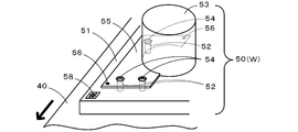
- FIG. The perspective view which shows a part of workpiece
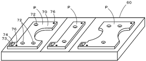
- FIG. The perspective view of the jig plate stand 60 in which the jig plate P was accommodated.
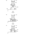
- FIG. 6 is a process diagram of an operation in which the jig plate gripping unit 22 grips the jig plate P.
- FIG. 1 is a schematic explanatory diagram of the robot arm control system 10
- FIG. 2 is a perspective view showing a part of a work 50 which is an example of the work W
- FIG. 3 is a perspective view of a jig plate base 60 in which the jig plate P is accommodated. is there.
- the robot arm control system 10 includes first and second robots 20 and 30, a workpiece transfer device 40, a jig plate base 60, and a system control unit 80.
- the first robot 20 includes a first arm 21, a jig plate holding unit 22, and a first camera 24.
- the first arm 21 is a multi-axis robot arm, and can turn horizontally and rotate vertically in the direction of the dashed-dotted arrow shown in FIG.
- the jig plate gripping unit 22 is attached to the tip of the first arm 21.
- the jig plate gripping unit 22 selects and grips one jig plate P from a plurality of types of jig plates P accommodated in the jig plate base 60, or holds the jig plate P being gripped by the jig plate base 60. Or return to a predetermined storage position.
- the jig plate gripping unit 22 includes a pair of fingers 23 and 23.
- the pair of fingers 23 and 23 are members extending in the vertical direction, and horizontally move in a direction approaching each other or horizontally moved away from each other by a finger actuator (not shown).
- the first camera 24 is disposed adjacent to the jig plate gripping unit 22 so as to be able to photograph the lower area of the arm tip. The operations of the first arm 21, the jig plate gripping unit 22, and the first camera 24 are controlled by the system control unit 80.
- the second robot 30 includes a second arm 31, a screw fastening unit 32, and a second camera 34.
- the second arm 31 is a multi-axis robot arm, and can be turned horizontally or vertically in the direction indicated by the dashed line in FIG.
- the screw tightening unit 32 is attached to the tip of the second arm 31.
- the screw tightening unit 32 is a unit that performs screw tightening on the work W that has been transported to the work position by the work transport device 40.
- the screw tightening unit 32 includes a driver 33.
- the driver 33 is attached so that the longitudinal direction of the driver 33 coincides with the vertical direction, and is rotated in the screw tightening direction by a driver actuator (not shown).
- the driver 33 can suck a screw at the tip by a vacuum method.
- the second camera 34 is installed adjacent to the screw tightening unit 32 so as to be able to photograph the lower area of the arm tip.
- the work transfer device 40 is a conveyor belt that carries the work W into the work position of the first and second robots 20 and 30 and carries out the work W that has been finished from the work position, and is perpendicular to the paper surface of FIG.
- the workpiece W is transported in any direction.
- the operation of the work transfer device 40 is controlled by the system control unit 80.
- a workpiece 50 which is an example of the workpiece W is shown in FIG.
- the work 50 includes a board 51 having a plurality of (here, three) screw holes 52 on the upper surface and a plate-like bracket having a plurality (here, three) screw insertion holes 54 penetrating in the vertical direction.
- 55 is a laminated body in which a cylindrical part 53 integrated with 55 is stacked up and down.
- the screw insertion hole 54 provided in the bracket 55 is disposed immediately above the screw hole 52 of the substrate 51.
- the component 53 is mounted on the substrate 51 by screwing a screw through a screw insertion hole 54 provided in the bracket 55 into the screw hole 52 of the substrate 51.
- the bracket 55 has reference marks 56 at two positions for alignment with the jig plate P.
- a two-dimensional barcode 58 is attached to a portion of the substrate 51 where the component 53 is not placed.
- the two-dimensional bar code 58 indicates a work type.
- the workpiece W is basically a laminated body in which components with brackets are stacked on a substrate, like the workpiece 50, and the shape of the bracket, the number and position of screw insertion holes, the shape of the component, the shape of the substrate, The number and position of screw holes are different for each type.
- the jig plate base 60 accommodates multiple types of jig plates P.
- FIG. 3 shows an example in which the jig plate base 60 accommodates three types of jig plates P.
- Each jig plate P is formed in a shape corresponding to the type of workpiece W.
- the jig plate 70 on the left side of FIG. 3 corresponding to the workpiece 50 of FIG. 2 will be described.
- the jig plate 70 is formed in the same shape as the bracket 55 of the workpiece 50, and is placed on the bracket 55 to press the bracket 55 against the substrate 51.
- the jig plate 70 has a guide hole 72 at a position matching the screw insertion hole 54 and the screw hole 52.
- the guide hole 72 is a tapered hole formed so that its diameter decreases downward.
- the lower diameter (small diameter) of the guide hole 72 is formed to be slightly larger than the diameter of the head of the screw to be used.
- the jig plate 70 serves to help the screw to be inserted into the screw hole 52 through the screw insertion hole 54 using the guide hole 72.
- the screw insertion hole 54 is designed to have a size that allows the foot portion of the screw to be inserted in a play but the head portion of the screw cannot be inserted.
- a tab 73 is provided at one corner of the jig plate 70, and the tab 73 is provided with a square hole 74 penetrating in the vertical direction.
- the jig plate gripping unit 22 of the first robot 20 grips the jig plate 70 using the square holes 74.
- Plural types of jig plates P are prepared corresponding to the types of workpieces W, but the shape and size of the square holes are made common.
- the position for accommodating each type of jig plate P is determined.
- the system control unit 80 is configured as a microprocessor centered on the CPU 81, and includes a ROM 82 for storing processing programs, an HDD 83 for storing various data, a RAM 84 used as a work area, and the like.
- the HDD 83 stores a correspondence table 83T that represents the correspondence between the work type and the jig plate type. For example, the workpiece type A corresponds to the jig plate type a, the workpiece type B corresponds to the jig plate type b, and so on.
- the system control unit 80 controls the first arm 21 to hold the jig plate directly above the square hole 74 of the jig plate 70 accommodated in the jig plate base 60.
- a pair of fingers 23 and 23 of the unit 22 are arranged. At this time, the pair of fingers 23 and 23 are close to each other, that is, in a closed state.
- FIG. 4A the system control unit 80 controls the first arm 21 to hold the jig plate directly above the square hole 74 of the jig plate 70 accommodated in the jig plate base 60.
- a pair of fingers 23 and 23 of the unit 22 are arranged. At this time, the pair of fingers 23 and 23 are close to each other, that is, in a closed state.
- the system control unit 80 controls the first arm 21 to insert the closed pair of fingers 23 and 23 into the square hole 74.
- the length of the finger 23 is the same as or slightly shorter than the depth of the square hole 74.
- the system control unit 80 controls the jig plate gripping unit 22 to horizontally move the pair of fingers 23 and 23 inserted into the square holes 74 away from each other. Let Then, the pair of fingers 23 and 23 are in an open state, and the outer surface of each finger 23 is pressed against the inner wall surface of the square hole 74.
- the jig plate 70 is gripped by the pair of fingers 23, 23, and the first arm 21 can grip the jig plate 70 and carry it to a predetermined position in the three-dimensional space.
- the system control unit 80 places the jig plate 70 in a predetermined accommodation position of the jig plate base 60, and then closes the pair of fingers 23, 23.
- the outer surface of 23 is separated from the inner wall surface of the square hole 74, and then the pair of fingers 23, 23 are raised and removed from the square hole 74.
- FIG. 5 is a flowchart of an automatic screw tightening processing routine.
- the CPU 81 of the system control unit 80 controls the work transfer device 40 to carry the work W into the work positions of the first and second robots 20 and 30 as shown in FIG. 1 (step S110). Subsequently, the CPU 81 reads the two-dimensional barcode attached to the work W (step S120). Specifically, the CPU 81 controls the first arm 21 to place the first camera 24 above the two-dimensional barcode of the work W, and causes the first camera 24 to image the two-dimensional barcode. Subsequently, the CPU 81 recognizes the jig plate type (step S130). Specifically, the CPU 81 recognizes the type of the workpiece W from the captured two-dimensional barcode image, and the correspondence table 83T (FIG.
- step S140 the CPU 81 acquires production related information corresponding to the jig plate type (step S140). Specifically, the CPU 81 reads and obtains production related information corresponding to the jig plate type recognized in step S130 from the correspondence table 83T.
- the CPU 81 determines whether or not the first arm 21 is currently gripping the jig plate P (step S150). If the first arm 21 is not gripping the jig plate P, the first arm 21 is determined. The jig plate P of this time is gripped (step S180). Specifically, the CPU 81 jigs the pair of fingers 23 and 23 of the first arm 21 based on various position coordinates on the jig plate base 60 of the current jig plate P from the production related information recognized in step S140. It arrange
- step S160 it is determined whether the jig plate P needs to be replaced. Specifically, the CPU 81 determines whether or not the type of the jig plate P currently gripped matches the type of the jig plate recognized in step S130. If they match, the CPU 81 does not need to be replaced and must match. It is determined that replacement is necessary. If it is necessary to replace the jig plate P in step S160, the CPU 81 returns the jig plate P held by the first arm 21 to the predetermined accommodation position on the jig plate base 60 (step S170), and then the step. Proceeding to S180, the first arm 21 is caused to grip the current jig plate P.
- step S180 the CPU 81 presses the workpiece W with the jig plate P gripped by the first arm 21 (step S190). Subsequently, the CPU 81 controls the second arm 31 and the screw tightening unit 32 to perform screw tightening of the workpiece W (step S200).
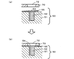
- steps S190 and S200 when the workpiece W is the workpiece 50 in FIG. 2 and the corresponding jig plate P is the jig plate 70 in FIG. 3 will be described below. These processes are executed in a state where the work 50 is left on the conveyor belt of the work transfer device 40. 6 and 7 are work process diagrams of these processes.
- the CPU 81 causes the second camera 34 of the second arm 31 to image the workpiece 50 from above the workpiece 50, and 2 provided on the bracket 55 of the workpiece 50 based on the image obtained by imaging. The positions of the two reference marks 56 and 56 are recognized.
- the CPU 81 controls the first arm 21 so that the two reference marks 76 and 76 of the jig plate 70 held by the first arm 21 coincide with the two reference marks 56 and 56 of the workpiece 50.
- the jig plate 70 is positioned. Thereby, the three guide holes 72 of the jig plate 70 are disposed immediately above the three screw insertion holes 54 of the bracket 55 of the workpiece 50 and the screw holes 52 of the substrate 51 (see FIG. 6A).
- the CPU 81 lowers the jig plate 70 and presses the bracket 55 of the workpiece 50 with the jig plate 70 (see FIG. 6B).
- bracket 55 is a thin plate, a part of the bracket 55 of the work 50 conveyed to the work position may be lifted from the substrate 51 (see FIG. 6A). Even in such a case, since the bracket 55 is pressed by the jig plate 70, the lifting is eliminated and the bracket 55 is in close contact with the substrate 51.
- step S ⁇ b> 200 the CPU 81 controls the second arm 31 to position the driver 33 of the screw tightening unit 32 at the screw supply position to which the type of screw 90 corresponding to the workpiece 50 is supplied.
- the head 92 of the screw 90 is adsorbed in a manner (see FIG. 7A).
- the coordinates of the screw supply position to which the screw 90 is supplied are those included in the production related information acquired in step S140.
- the CPU 81 controls the second arm 31 to position the foot portion 94 of the screw 90 attracted by the driver 33 so as to be coaxial with the guide hole 72 of the jig plate 70 (see FIG. 7B). ).
- the CPU 81 controls the second arm 31 to lower the driver 33.
- the foot portion 94 of the screw 90 attracted by the driver 33 passes through the guide hole 72 of the jig plate 70 and the screw insertion hole 54 of the bracket 55 and reaches the screw hole 52 of the substrate 51.
- the guide hole 72 is a tapered hole
- the foot portion 94 of the screw 90 is guided to the screw hole 52 while being guided by the side wall of the guide hole 72.
- the CPU 81 controls the second arm 31 and the screw tightening unit 32 to rotate the driver 33 and screw the foot portion 94 of the screw 90 into the screw hole 52 (see FIG. 7C).
- the bracket 55 of the workpiece 50 is fastened to the substrate 51 with the screws 90.
- the CPU 81 controls the screw tightening unit 32 to stop the rotation of the driver 33 and releases the suction of the screw 90 by the driver 33, and controls the second arm 31 to move the driver 33 upward. Evacuate. Further, the CPU 81 controls the first arm 21 to retract the jig plate 70 upward.
- step S200 the CPU 81 controls the work transfer device 40 to carry out the work W after the completion of the screw tightening from the work position (step S210). Thereafter, the CPU 81 determines whether or not all the screw tightening operations have been completed (step S220), and if the screw tightening operation still remains, the processing after S110 is executed again. On the other hand, if all screw tightening operations have been completed in step S220, the CPU 81 ends this routine.
- the robot arm control system 10 of this embodiment corresponds to the robot arm control system of the present invention
- the first and second arms 21 and 31 correspond to the first and second robot arms
- the first camera 24 and the CPU 81 are provided.
- the jig plate base 60 corresponds to the jig plate housing means
- the HDD 83 corresponds to the storage means
- the CPU 81 corresponds to the control means.
- the first arm 21 can automatically take out the jig plate P corresponding to the workpieces W from the jig plate base 60. . Further, even if the workpiece W may partially lift (for example, the workpiece 50 in FIG. 6A), the workpiece W can be prevented from being lifted by pressing the workpiece W with the jig plate P suitable for the workpiece W. . Therefore, the work efficiency when working with holding various types of workpieces W with the jig plate P is increased.
- the current jig plate P gripped by the first arm 21 does not correspond to the type of the workpiece W to be worked on, the current jig plate P is returned to the jig plate base 60. After that, the jig plate P corresponding to the type of the workpiece W to be worked on is taken out from the jig plate base 60. Therefore, the jig plate P corresponding to the work type can be automatically replaced.
- the component 53 with the bracket 55 having the screw insertion hole 54 can be automatically fastened to the board 51 having the screw hole 52 with a screw. Since the bracket 55 may float from the substrate 51, it is highly significant to apply the present invention.
- the workpiece W is transported to the work position of the first and second arms 21 and 31 by the conveyor belt of the workpiece transport device 40, and is left on the conveyor belt by the first and second arms 21 and 31. Work. Therefore, the workpieces W can be successively transferred to the work position by the conveyor belt. In addition, the work efficiency is increased because there is no need to lift the workpiece W.
- the square holes of the jig plate P and the pair of fingers 23 and 23 are used.
- the embodiment is not particularly limited thereto.
- a holder similar to the nozzle holder having an L-shaped notch disclosed in FIG. 6 of WO2015 / 111156 may be provided in the jig plate gripping unit 22.
- the jig plate P is provided with a round hole instead of a square hole, and a pair of pins protruding in the radial direction of the hole are provided so as to face each other, and the pair of pins are detachably held by the holder. May be.
- the jig plate holding unit 22 may detachably hold the jig plate P by utilizing excitation and demagnetization of the electromagnet.
- the workpiece W is conveyed to the conveyor belt of the workpiece conveying device 40.
- the workpiece W is conveyed by the conveyor belt of the workpiece conveying device 40 while being placed on the workpiece holding plate. May be.
- the two-dimensional barcode may be affixed to the workpiece W as described above, or may be affixed to the workpiece holding plate.
- a two-dimensional barcode is used, but a striped barcode or an RF tag in which ID information is embedded may be used.
- the workpiece W and the jig plate P are positioned using the reference mark, but may be mechanically positioned.
- an L-shaped wall may be provided so as to surround one corner of the workpiece W, and positioning may be performed by applying a corner of the jig plate P to the L-shaped wall.
- convex portions are provided at two or more locations on the upper surface of the workpiece W, concave portions that fit into the convex portions are provided on the lower surface of the jig plate P, and the concave portions of the jig plate P are fitted into the convex portions of the workpiece W. Positioning may be performed.
- the present invention is not particularly limited thereto.
- the present invention may be applied to an operation in which the first arm 21 presses a work having a female connector (inserted portion) with a jig plate and the second arm 31 inserts a male connector (insertion tool) into the female connector.
- the present invention may be applied to an operation in which the first arm 21 presses a work having a slot (inserted portion) with a jig plate and the second robot 20 fits a component (insertion tool) into the slot.
- the system control unit 80 directly controls the operation of the first and second arms 21 and 31, but is not particularly limited thereto.
- the first robot 20 includes a first control unit that controls operations of the first arm 21, the jig plate gripping unit 22, and the first camera 24, and the second robot 30 includes the second arm 31, the screw tightening unit 32, the first
- the system control unit 80 performs two-way communication with the first and second control units, and the first and second robots through the first and second control units. The operations of the arms 21 and 31 may be controlled.
- the present invention can be used for a device that automatically tightens screws or a device that automatically inserts a male connector into a female connector.
- 10 robot arm control system 20 1st robot, 21 1st arm, 22 jig plate gripping unit, 23 fingers, 24 1st camera, 30 2nd robot, 31 2nd arm, 32 screw tightening unit, 33 driver, 34th 2 cameras, 40 workpiece transfer devices, 50 workpieces, 51 substrates, 52 screw holes, 53 parts, 54 screw insertion holes, 55 brackets, 56 fiducial marks, 58 two-dimensional barcode, 60 jig plate base, 70 jig plates, 72 guides Hole, 73 tab, 74 square hole, 76 fiducial mark, 80 system control unit, 81 CPU, 82 ROM, 83 HDD, 83T correspondence table, 84 RAM, 90 screws, 92 head, 94 foot, P jig plate, W work.
Landscapes
- Engineering & Computer Science (AREA)
- Mechanical Engineering (AREA)
- Robotics (AREA)
- Automatic Assembly (AREA)
- Manipulator (AREA)
Abstract
Priority Applications (4)
| Application Number | Priority Date | Filing Date | Title |
|---|---|---|---|
| CN201680081864.8A CN108698178B (zh) | 2016-02-26 | 2016-02-26 | 机器人手臂控制系统 |
| PCT/JP2016/055767 WO2017145349A1 (fr) | 2016-02-26 | 2016-02-26 | Système de commande de bras de robot |
| JP2018501518A JP6674529B2 (ja) | 2016-02-26 | 2016-02-26 | ロボットアーム制御システム |
| EP16891506.4A EP3421172B1 (fr) | 2016-02-26 | 2016-02-26 | Système de commande de bras de robot |
Applications Claiming Priority (1)
| Application Number | Priority Date | Filing Date | Title |
|---|---|---|---|
| PCT/JP2016/055767 WO2017145349A1 (fr) | 2016-02-26 | 2016-02-26 | Système de commande de bras de robot |
Publications (1)
| Publication Number | Publication Date |
|---|---|
| WO2017145349A1 true WO2017145349A1 (fr) | 2017-08-31 |
Family
ID=59685969
Family Applications (1)
| Application Number | Title | Priority Date | Filing Date |
|---|---|---|---|
| PCT/JP2016/055767 Ceased WO2017145349A1 (fr) | 2016-02-26 | 2016-02-26 | Système de commande de bras de robot |
Country Status (4)
| Country | Link |
|---|---|
| EP (1) | EP3421172B1 (fr) |
| JP (1) | JP6674529B2 (fr) |
| CN (1) | CN108698178B (fr) |
| WO (1) | WO2017145349A1 (fr) |
Cited By (14)
| Publication number | Priority date | Publication date | Assignee | Title |
|---|---|---|---|---|
| CN107856022A (zh) * | 2017-11-29 | 2018-03-30 | 苏州弘瀚自动化科技有限公司 | 一种取料机械臂 |
| CN108857376A (zh) * | 2018-06-04 | 2018-11-23 | 中车青岛四方机车车辆股份有限公司 | 一种零件的自动装配装置 |
| CN109614830A (zh) * | 2017-10-04 | 2019-04-12 | 发那科株式会社 | 识别代码读取装置以及机器学习装置 |
| JP2019119005A (ja) * | 2018-01-05 | 2019-07-22 | 株式会社Fdkエンジニアリング | 部品組付装置の較正方法 |
| CN110561415A (zh) * | 2019-07-30 | 2019-12-13 | 苏州紫金港智能制造装备有限公司 | 一种基于机器视觉补偿的双机器人协同装配系统及方法 |
| WO2020104354A1 (fr) * | 2018-11-21 | 2020-05-28 | Siemens Aktiengesellschaft | Dispositif de liaison par complémentarité de formes et/ou à force et procédé |
| WO2020241900A1 (fr) * | 2019-05-31 | 2020-12-03 | 川崎重工業株式会社 | Dispositif d'assemblage de cartes, et procédé d'assemblage de cartes |
| JP2021045824A (ja) * | 2019-09-19 | 2021-03-25 | 株式会社安川電機 | 搬送システム、搬送方法、ロボット |
| JP6935570B1 (ja) * | 2020-10-29 | 2021-09-15 | 株式会社北川鉄工所 | 治具自動交換システム |
| CN114102113A (zh) * | 2020-08-28 | 2022-03-01 | 杰瑞姆株式会社 | 使用双臂水平关节型机器人的自动螺栓紧固装置 |
| CN114929429A (zh) * | 2020-02-17 | 2022-08-19 | 川崎重工业株式会社 | 插入良好度判定器、插入良好度判定装置、机器人系统以及插入良好度判定方法 |
| CN115255905A (zh) * | 2022-06-22 | 2022-11-01 | 日照市越疆智能科技有限公司 | 工业机器人关节的自动预装设备、方法及存储介质 |
| CN115648281A (zh) * | 2022-10-28 | 2023-01-31 | 东风汽车有限公司东风日产乘用车公司 | 一种缸体包装生产线 |
| CN119175694A (zh) * | 2024-11-25 | 2024-12-24 | 香港科技大学(广州) | 一种ebl协作机械手 |
Families Citing this family (8)
| Publication number | Priority date | Publication date | Assignee | Title |
|---|---|---|---|---|
| CN111251336B (zh) * | 2019-06-29 | 2022-01-28 | 浙江大学 | 一种基于视觉定位的双臂协同智能装配系统 |
| DE102019123245B4 (de) * | 2019-08-29 | 2021-06-24 | Rittal Gmbh & Co. Kg | Verfahren für die Bestückung einer Montageplatte mit Bestückungskomponenten einer Schalt- und/oder Steuerungsanlage |
| CN110524228B (zh) * | 2019-10-30 | 2020-03-10 | 广东博智林机器人有限公司 | 销钉安装机器人 |
| US11888262B2 (en) * | 2020-01-03 | 2024-01-30 | Aptiv Technologies Limited | Automotive electrical connector features for robotic installation |
| CN111251292B (zh) * | 2020-01-13 | 2021-08-10 | 佛山缔乐视觉科技有限公司 | 基于视觉定位的工件装配方法、装置和存储介质 |
| CN113714243A (zh) * | 2020-05-25 | 2021-11-30 | 北京恒驰智能科技有限公司 | 一种智能电能表自动拆解线 |
| CN112192569A (zh) * | 2020-10-09 | 2021-01-08 | 常熟云开智能科技有限公司 | 一种打磨机器人自动识别工件、自动更换夹具的控制方法 |
| KR102925398B1 (ko) | 2021-06-23 | 2026-02-10 | 현대모비스 주식회사 | 협동로봇을 이용하는 부품 체결시스템 및 이의 체결방법 |
Citations (2)
| Publication number | Priority date | Publication date | Assignee | Title |
|---|---|---|---|---|
| JPH01321185A (ja) * | 1988-06-22 | 1989-12-27 | Fujitsu Ltd | 視覚情報を用いた2腕協調ロボットによるプリンタヘッドの組立システム |
| JP2012071400A (ja) * | 2010-09-29 | 2012-04-12 | Yaskawa Electric Corp | 部品組み付け装置及び機械部品の製造方法 |
Family Cites Families (7)
| Publication number | Priority date | Publication date | Assignee | Title |
|---|---|---|---|---|
| JPS6056830A (ja) * | 1983-09-05 | 1985-04-02 | Hitachi Ltd | ロボツトを用いた組立装置 |
| JPH09141577A (ja) * | 1995-11-20 | 1997-06-03 | Tokico Ltd | マスキング装置 |
| JP2010125553A (ja) * | 2008-11-27 | 2010-06-10 | Sharp Corp | 自動ネジ締め装置 |
| JP6000579B2 (ja) * | 2012-03-09 | 2016-09-28 | キヤノン株式会社 | 情報処理装置、情報処理方法 |
| JP5741617B2 (ja) * | 2013-03-19 | 2015-07-01 | 株式会社安川電機 | ロボット装置 |
| CN203471298U (zh) * | 2013-08-02 | 2014-03-12 | 昌硕科技(上海)有限公司 | 自动锁螺钉机 |
| CN104608128A (zh) * | 2013-11-01 | 2015-05-13 | 精工爱普生株式会社 | 机器人、控制装置、机器人系统、以及机器人控制方法 |
-
2016
- 2016-02-26 JP JP2018501518A patent/JP6674529B2/ja active Active
- 2016-02-26 EP EP16891506.4A patent/EP3421172B1/fr active Active
- 2016-02-26 WO PCT/JP2016/055767 patent/WO2017145349A1/fr not_active Ceased
- 2016-02-26 CN CN201680081864.8A patent/CN108698178B/zh active Active
Patent Citations (2)
| Publication number | Priority date | Publication date | Assignee | Title |
|---|---|---|---|---|
| JPH01321185A (ja) * | 1988-06-22 | 1989-12-27 | Fujitsu Ltd | 視覚情報を用いた2腕協調ロボットによるプリンタヘッドの組立システム |
| JP2012071400A (ja) * | 2010-09-29 | 2012-04-12 | Yaskawa Electric Corp | 部品組み付け装置及び機械部品の製造方法 |
Cited By (26)
| Publication number | Priority date | Publication date | Assignee | Title |
|---|---|---|---|---|
| CN109614830A (zh) * | 2017-10-04 | 2019-04-12 | 发那科株式会社 | 识别代码读取装置以及机器学习装置 |
| US10960550B2 (en) | 2017-10-04 | 2021-03-30 | Fanuc Corporation | Identification code reading apparatus and machine learning device |
| CN107856022A (zh) * | 2017-11-29 | 2018-03-30 | 苏州弘瀚自动化科技有限公司 | 一种取料机械臂 |
| JP2019119005A (ja) * | 2018-01-05 | 2019-07-22 | 株式会社Fdkエンジニアリング | 部品組付装置の較正方法 |
| JP7064884B2 (ja) | 2018-01-05 | 2022-05-11 | 株式会社Fdkエンジニアリング | 部品組付装置の較正方法 |
| CN108857376A (zh) * | 2018-06-04 | 2018-11-23 | 中车青岛四方机车车辆股份有限公司 | 一种零件的自动装配装置 |
| WO2020104354A1 (fr) * | 2018-11-21 | 2020-05-28 | Siemens Aktiengesellschaft | Dispositif de liaison par complémentarité de formes et/ou à force et procédé |
| US11668331B2 (en) | 2018-11-21 | 2023-06-06 | Siemens Aktiengesellschaft | Device for interlocking and/or frictional connection, and method |
| CN113165165A (zh) * | 2018-11-21 | 2021-07-23 | 西门子股份公司 | 用于形状配合和/或力配合的连接的装置和方法 |
| JP7200046B2 (ja) | 2019-05-31 | 2023-01-06 | 川崎重工業株式会社 | 基板組立装置及び基板組立方法 |
| WO2020241900A1 (fr) * | 2019-05-31 | 2020-12-03 | 川崎重工業株式会社 | Dispositif d'assemblage de cartes, et procédé d'assemblage de cartes |
| JP2020196069A (ja) * | 2019-05-31 | 2020-12-10 | 川崎重工業株式会社 | 基板組立装置及び基板組立方法 |
| CN110561415A (zh) * | 2019-07-30 | 2019-12-13 | 苏州紫金港智能制造装备有限公司 | 一种基于机器视觉补偿的双机器人协同装配系统及方法 |
| JP2021045824A (ja) * | 2019-09-19 | 2021-03-25 | 株式会社安川電機 | 搬送システム、搬送方法、ロボット |
| US11786997B2 (en) * | 2020-02-17 | 2023-10-17 | Kawasaki Jukogyo Kabushiki Kaisha | Insertion quality determinator, insertion quality determining device, robot system, and method of determining insertion quality |
| CN114929429B (zh) * | 2020-02-17 | 2024-04-05 | 川崎重工业株式会社 | 插入良好度判定器、插入良好度判定装置、机器人系统以及插入良好度判定方法 |
| CN114929429A (zh) * | 2020-02-17 | 2022-08-19 | 川崎重工业株式会社 | 插入良好度判定器、插入良好度判定装置、机器人系统以及插入良好度判定方法 |
| US20230109560A1 (en) * | 2020-02-17 | 2023-04-06 | Kawasaki Jukogyo Kabushiki Kaisha | Insertion quality determinator, insertion quality determining device, robot system, and method of determining insertion quality |
| CN114102113A (zh) * | 2020-08-28 | 2022-03-01 | 杰瑞姆株式会社 | 使用双臂水平关节型机器人的自动螺栓紧固装置 |
| CN114102113B (zh) * | 2020-08-28 | 2024-03-08 | 杰瑞姆株式会社 | 使用双臂水平关节型机器人的自动螺栓紧固装置 |
| WO2022091994A1 (fr) * | 2020-10-29 | 2022-05-05 | 株式会社北川鉄工所 | Système de remplacement automatique de gabarit |
| JP6935570B1 (ja) * | 2020-10-29 | 2021-09-15 | 株式会社北川鉄工所 | 治具自動交換システム |
| US12544873B2 (en) | 2020-10-29 | 2026-02-10 | Kitagawa Iron Works Co., Ltd. | Automatic jig replacement system |
| CN115255905A (zh) * | 2022-06-22 | 2022-11-01 | 日照市越疆智能科技有限公司 | 工业机器人关节的自动预装设备、方法及存储介质 |
| CN115648281A (zh) * | 2022-10-28 | 2023-01-31 | 东风汽车有限公司东风日产乘用车公司 | 一种缸体包装生产线 |
| CN119175694A (zh) * | 2024-11-25 | 2024-12-24 | 香港科技大学(广州) | 一种ebl协作机械手 |
Also Published As
| Publication number | Publication date |
|---|---|
| CN108698178B (zh) | 2020-12-15 |
| CN108698178A (zh) | 2018-10-23 |
| EP3421172B1 (fr) | 2020-02-19 |
| JPWO2017145349A1 (ja) | 2018-12-13 |
| EP3421172A4 (fr) | 2019-02-27 |
| EP3421172A1 (fr) | 2019-01-02 |
| JP6674529B2 (ja) | 2020-04-01 |
Similar Documents
| Publication | Publication Date | Title |
|---|---|---|
| JP6674529B2 (ja) | ロボットアーム制御システム | |
| JP5885230B2 (ja) | ダイ位置判定システム。 | |
| CN119175694B (zh) | 一种ebl协作机械手 | |
| WO2015052753A1 (fr) | Mandrin et dispositif de montage de pièces | |
| WO2016092658A1 (fr) | Élément de logement de composant, et procédé de logement de composant | |
| US10005186B2 (en) | Workpiece conveying device having positioning structure | |
| WO2016181437A1 (fr) | Machine de montage de composants, et procédé de distribution de composants pour machine de montage de composants | |
| CN109792859B (zh) | 元件安装机 | |
| JP2018098311A (ja) | 部品取出し方法および部品取出し装置ならびに部品実装装置 | |
| JP7664936B2 (ja) | 表示装置、および干渉確認方法 | |
| JP2655516B2 (ja) | ワーク加工装置及びワーク加工方法 | |
| US20200015397A1 (en) | Data creation device and data creation method | |
| JP7070494B2 (ja) | 生産システム及び制御装置 | |
| JP3163881B2 (ja) | ダイボンディング装置およびダイボンディング方法 | |
| US11992957B2 (en) | Mounting-related device and rail device | |
| JP3230695B2 (ja) | ワークの切断・搬出装置 | |
| JP7365650B2 (ja) | スクリーン印刷機 | |
| JP5878082B2 (ja) | クリンチ装置、部品取付装置 | |
| JP6847214B2 (ja) | 部品判定システム、および部品判定方法 | |
| CN120941005B (zh) | 汽车滤芯自动化装配工作站及其装配方法 | |
| JP6603318B2 (ja) | 部品実装装置 | |
| JP7390642B2 (ja) | 搬送装置 | |
| JP4925762B2 (ja) | 部品実装装置 | |
| JP2008218554A (ja) | バックアッププレート | |
| JP2009010084A (ja) | 樹脂封止装置 |
Legal Events
| Date | Code | Title | Description |
|---|---|---|---|
| ENP | Entry into the national phase |
Ref document number: 2018501518 Country of ref document: JP Kind code of ref document: A |
|
| NENP | Non-entry into the national phase |
Ref country code: DE |
|
| WWE | Wipo information: entry into national phase |
Ref document number: 2016891506 Country of ref document: EP |
|
| ENP | Entry into the national phase |
Ref document number: 2016891506 Country of ref document: EP Effective date: 20180926 |
|
| 121 | Ep: the epo has been informed by wipo that ep was designated in this application |
Ref document number: 16891506 Country of ref document: EP Kind code of ref document: A1 |