WO2017145456A1 - 電力取引マッチングシステム、電力取引マッチング方法および電力取引マッチングプログラム - Google Patents
電力取引マッチングシステム、電力取引マッチング方法および電力取引マッチングプログラム Download PDFInfo
- Publication number
- WO2017145456A1 WO2017145456A1 PCT/JP2016/083959 JP2016083959W WO2017145456A1 WO 2017145456 A1 WO2017145456 A1 WO 2017145456A1 JP 2016083959 W JP2016083959 W JP 2016083959W WO 2017145456 A1 WO2017145456 A1 WO 2017145456A1
- Authority
- WO
- WIPO (PCT)
- Prior art keywords
- power
- consumer
- amount
- surplus
- information
- Prior art date
- Legal status (The legal status is an assumption and is not a legal conclusion. Google has not performed a legal analysis and makes no representation as to the accuracy of the status listed.)
- Ceased
Links
Images


Classifications
-
- G—PHYSICS
- G06—COMPUTING OR CALCULATING; COUNTING
- G06Q—INFORMATION AND COMMUNICATION TECHNOLOGY [ICT] SPECIALLY ADAPTED FOR ADMINISTRATIVE, COMMERCIAL, FINANCIAL, MANAGERIAL OR SUPERVISORY PURPOSES; SYSTEMS OR METHODS SPECIALLY ADAPTED FOR ADMINISTRATIVE, COMMERCIAL, FINANCIAL, MANAGERIAL OR SUPERVISORY PURPOSES, NOT OTHERWISE PROVIDED FOR
- G06Q50/00—Information and communication technology [ICT] specially adapted for implementation of business processes of specific business sectors, e.g. utilities or tourism
- G06Q50/06—Energy or water supply
-
- G—PHYSICS
- G06—COMPUTING OR CALCULATING; COUNTING
- G06Q—INFORMATION AND COMMUNICATION TECHNOLOGY [ICT] SPECIALLY ADAPTED FOR ADMINISTRATIVE, COMMERCIAL, FINANCIAL, MANAGERIAL OR SUPERVISORY PURPOSES; SYSTEMS OR METHODS SPECIALLY ADAPTED FOR ADMINISTRATIVE, COMMERCIAL, FINANCIAL, MANAGERIAL OR SUPERVISORY PURPOSES, NOT OTHERWISE PROVIDED FOR
- G06Q40/00—Finance; Insurance; Tax strategies; Processing of corporate or income taxes
- G06Q40/04—Trading; Exchange, e.g. stocks, commodities, derivatives or currency exchange
-
- H—ELECTRICITY
- H02—GENERATION; CONVERSION OR DISTRIBUTION OF ELECTRIC POWER
- H02J—ELECTRIC POWER NETWORKS; CIRCUIT ARRANGEMENTS OR SYSTEMS FOR SUPPLYING OR DISTRIBUTING ELECTRIC POWER; SYSTEMS FOR STORING ELECTRIC ENERGY
- H02J13/00—Circuit arrangements for providing remote monitoring or remote control of equipment in a power distribution network
- H02J13/12—Monitoring network conditions, e.g. electrical magnitudes or operational status
-
- H—ELECTRICITY
- H02—GENERATION; CONVERSION OR DISTRIBUTION OF ELECTRIC POWER
- H02J—ELECTRIC POWER NETWORKS; CIRCUIT ARRANGEMENTS OR SYSTEMS FOR SUPPLYING OR DISTRIBUTING ELECTRIC POWER; SYSTEMS FOR STORING ELECTRIC ENERGY
- H02J3/00—Circuit arrangements for AC mains or AC distribution networks
- H02J3/008—Circuit arrangements for power supply or distribution technologies responsive to energy trading
-
- H—ELECTRICITY
- H02—GENERATION; CONVERSION OR DISTRIBUTION OF ELECTRIC POWER
- H02J—ELECTRIC POWER NETWORKS; CIRCUIT ARRANGEMENTS OR SYSTEMS FOR SUPPLYING OR DISTRIBUTING ELECTRIC POWER; SYSTEMS FOR STORING ELECTRIC ENERGY
- H02J3/00—Circuit arrangements for AC mains or AC distribution networks
- H02J3/28—Arrangements for balancing of the load in networks by storage of energy
- H02J3/32—Arrangements for balancing of the load in networks by storage of energy using batteries or super capacitors with converting means
-
- H—ELECTRICITY
- H02—GENERATION; CONVERSION OR DISTRIBUTION OF ELECTRIC POWER
- H02J—ELECTRIC POWER NETWORKS; CIRCUIT ARRANGEMENTS OR SYSTEMS FOR SUPPLYING OR DISTRIBUTING ELECTRIC POWER; SYSTEMS FOR STORING ELECTRIC ENERGY
- H02J3/00—Circuit arrangements for AC mains or AC distribution networks
- H02J3/38—Arrangements for feeding a single network from two or more generators or sources in parallel; Arrangements for feeding already energised networks from additional generators or sources in parallel
- H02J3/381—Dispersed generators
-
- H—ELECTRICITY
- H02—GENERATION; CONVERSION OR DISTRIBUTION OF ELECTRIC POWER
- H02J—ELECTRIC POWER NETWORKS; CIRCUIT ARRANGEMENTS OR SYSTEMS FOR SUPPLYING OR DISTRIBUTING ELECTRIC POWER; SYSTEMS FOR STORING ELECTRIC ENERGY
- H02J2101/00—Supply or distribution of decentralised, dispersed or local electric power generation
- H02J2101/20—Dispersed power generation using renewable energy sources
- H02J2101/22—Solar energy
- H02J2101/24—Photovoltaics
-
- Y—GENERAL TAGGING OF NEW TECHNOLOGICAL DEVELOPMENTS; GENERAL TAGGING OF CROSS-SECTIONAL TECHNOLOGIES SPANNING OVER SEVERAL SECTIONS OF THE IPC; TECHNICAL SUBJECTS COVERED BY FORMER USPC CROSS-REFERENCE ART COLLECTIONS [XRACs] AND DIGESTS
- Y02—TECHNOLOGIES OR APPLICATIONS FOR MITIGATION OR ADAPTATION AGAINST CLIMATE CHANGE
- Y02E—REDUCTION OF GREENHOUSE GAS [GHG] EMISSIONS, RELATED TO ENERGY GENERATION, TRANSMISSION OR DISTRIBUTION
- Y02E10/00—Energy generation through renewable energy sources
- Y02E10/50—Photovoltaic [PV] energy
- Y02E10/56—Power conversion systems, e.g. maximum power point trackers
-
- Y—GENERAL TAGGING OF NEW TECHNOLOGICAL DEVELOPMENTS; GENERAL TAGGING OF CROSS-SECTIONAL TECHNOLOGIES SPANNING OVER SEVERAL SECTIONS OF THE IPC; TECHNICAL SUBJECTS COVERED BY FORMER USPC CROSS-REFERENCE ART COLLECTIONS [XRACs] AND DIGESTS
- Y02—TECHNOLOGIES OR APPLICATIONS FOR MITIGATION OR ADAPTATION AGAINST CLIMATE CHANGE
- Y02E—REDUCTION OF GREENHOUSE GAS [GHG] EMISSIONS, RELATED TO ENERGY GENERATION, TRANSMISSION OR DISTRIBUTION
- Y02E40/00—Technologies for an efficient electrical power generation, transmission or distribution
- Y02E40/70—Smart grids as climate change mitigation technology in the energy generation sector
-
- Y—GENERAL TAGGING OF NEW TECHNOLOGICAL DEVELOPMENTS; GENERAL TAGGING OF CROSS-SECTIONAL TECHNOLOGIES SPANNING OVER SEVERAL SECTIONS OF THE IPC; TECHNICAL SUBJECTS COVERED BY FORMER USPC CROSS-REFERENCE ART COLLECTIONS [XRACs] AND DIGESTS
- Y02—TECHNOLOGIES OR APPLICATIONS FOR MITIGATION OR ADAPTATION AGAINST CLIMATE CHANGE
- Y02E—REDUCTION OF GREENHOUSE GAS [GHG] EMISSIONS, RELATED TO ENERGY GENERATION, TRANSMISSION OR DISTRIBUTION
- Y02E60/00—Enabling technologies; Technologies with a potential or indirect contribution to GHG emissions mitigation
-
- Y—GENERAL TAGGING OF NEW TECHNOLOGICAL DEVELOPMENTS; GENERAL TAGGING OF CROSS-SECTIONAL TECHNOLOGIES SPANNING OVER SEVERAL SECTIONS OF THE IPC; TECHNICAL SUBJECTS COVERED BY FORMER USPC CROSS-REFERENCE ART COLLECTIONS [XRACs] AND DIGESTS
- Y04—INFORMATION OR COMMUNICATION TECHNOLOGIES HAVING AN IMPACT ON OTHER TECHNOLOGY AREAS
- Y04S—SYSTEMS INTEGRATING TECHNOLOGIES RELATED TO POWER NETWORK OPERATION, COMMUNICATION OR INFORMATION TECHNOLOGIES FOR IMPROVING THE ELECTRICAL POWER GENERATION, TRANSMISSION, DISTRIBUTION, MANAGEMENT OR USAGE, i.e. SMART GRIDS
- Y04S10/00—Systems supporting electrical power generation, transmission or distribution
- Y04S10/12—Monitoring or controlling equipment for energy generation units, e.g. distributed energy generation [DER] or load-side generation
- Y04S10/123—Monitoring or controlling equipment for energy generation units, e.g. distributed energy generation [DER] or load-side generation the energy generation units being or involving renewable energy sources
-
- Y—GENERAL TAGGING OF NEW TECHNOLOGICAL DEVELOPMENTS; GENERAL TAGGING OF CROSS-SECTIONAL TECHNOLOGIES SPANNING OVER SEVERAL SECTIONS OF THE IPC; TECHNICAL SUBJECTS COVERED BY FORMER USPC CROSS-REFERENCE ART COLLECTIONS [XRACs] AND DIGESTS
- Y04—INFORMATION OR COMMUNICATION TECHNOLOGIES HAVING AN IMPACT ON OTHER TECHNOLOGY AREAS
- Y04S—SYSTEMS INTEGRATING TECHNOLOGIES RELATED TO POWER NETWORK OPERATION, COMMUNICATION OR INFORMATION TECHNOLOGIES FOR IMPROVING THE ELECTRICAL POWER GENERATION, TRANSMISSION, DISTRIBUTION, MANAGEMENT OR USAGE, i.e. SMART GRIDS
- Y04S10/00—Systems supporting electrical power generation, transmission or distribution
- Y04S10/14—Energy storage units
-
- Y—GENERAL TAGGING OF NEW TECHNOLOGICAL DEVELOPMENTS; GENERAL TAGGING OF CROSS-SECTIONAL TECHNOLOGIES SPANNING OVER SEVERAL SECTIONS OF THE IPC; TECHNICAL SUBJECTS COVERED BY FORMER USPC CROSS-REFERENCE ART COLLECTIONS [XRACs] AND DIGESTS
- Y04—INFORMATION OR COMMUNICATION TECHNOLOGIES HAVING AN IMPACT ON OTHER TECHNOLOGY AREAS
- Y04S—SYSTEMS INTEGRATING TECHNOLOGIES RELATED TO POWER NETWORK OPERATION, COMMUNICATION OR INFORMATION TECHNOLOGIES FOR IMPROVING THE ELECTRICAL POWER GENERATION, TRANSMISSION, DISTRIBUTION, MANAGEMENT OR USAGE, i.e. SMART GRIDS
- Y04S10/00—Systems supporting electrical power generation, transmission or distribution
- Y04S10/30—State monitoring, e.g. fault, temperature monitoring, insulator monitoring, corona discharge
-
- Y—GENERAL TAGGING OF NEW TECHNOLOGICAL DEVELOPMENTS; GENERAL TAGGING OF CROSS-SECTIONAL TECHNOLOGIES SPANNING OVER SEVERAL SECTIONS OF THE IPC; TECHNICAL SUBJECTS COVERED BY FORMER USPC CROSS-REFERENCE ART COLLECTIONS [XRACs] AND DIGESTS
- Y04—INFORMATION OR COMMUNICATION TECHNOLOGIES HAVING AN IMPACT ON OTHER TECHNOLOGY AREAS
- Y04S—SYSTEMS INTEGRATING TECHNOLOGIES RELATED TO POWER NETWORK OPERATION, COMMUNICATION OR INFORMATION TECHNOLOGIES FOR IMPROVING THE ELECTRICAL POWER GENERATION, TRANSMISSION, DISTRIBUTION, MANAGEMENT OR USAGE, i.e. SMART GRIDS
- Y04S10/00—Systems supporting electrical power generation, transmission or distribution
- Y04S10/50—Systems or methods supporting the power network operation or management, involving a certain degree of interaction with the load-side end user applications
-
- Y—GENERAL TAGGING OF NEW TECHNOLOGICAL DEVELOPMENTS; GENERAL TAGGING OF CROSS-SECTIONAL TECHNOLOGIES SPANNING OVER SEVERAL SECTIONS OF THE IPC; TECHNICAL SUBJECTS COVERED BY FORMER USPC CROSS-REFERENCE ART COLLECTIONS [XRACs] AND DIGESTS
- Y04—INFORMATION OR COMMUNICATION TECHNOLOGIES HAVING AN IMPACT ON OTHER TECHNOLOGY AREAS
- Y04S—SYSTEMS INTEGRATING TECHNOLOGIES RELATED TO POWER NETWORK OPERATION, COMMUNICATION OR INFORMATION TECHNOLOGIES FOR IMPROVING THE ELECTRICAL POWER GENERATION, TRANSMISSION, DISTRIBUTION, MANAGEMENT OR USAGE, i.e. SMART GRIDS
- Y04S50/00—Market activities related to the operation of systems integrating technologies related to power network operation or related to communication or information technologies
- Y04S50/10—Energy trading, including energy flowing from end-user application to grid
Definitions
- the present invention relates to a power transaction matching system, a power transaction matching method, and a power transaction matching program.
- a power generation apparatus for example, a solar power generation apparatus
- a surplus power purchase system has been established, so that electric power generated by a solar power generation device, a wind power generation device, or the like can be sold to an electric power company.
- the generated power may not be sold to the power company.
- output suppression a predetermined amount of power that can be purchased by an electric power company is exceeded (hereinafter referred to as output suppression). For this reason, a consumer may use a storage battery that can temporarily store power that could not be sold.
- the power generated by the power generation device may have to be discarded.
- information on the power amount, time zone, and price of the purchased power bid is matched with information on the power amount, time zone, and price of the sold power bid, and surpluses among a plurality of consumers.
- An electric power transaction mediation system that can exchange electric power is disclosed.
- the conventional power transaction mediation system has the following problems.
- the disadvantage of the bid of the power generation company is eliminated and the transaction volume is increased.
- An object of the present invention is to provide an electric power transaction matching system, an electric power transaction matching method, and an electric power transaction matching program that can efficiently exchange surplus power among a plurality of consumers who own a power generation device and a storage battery. There is.
- An electric power transaction matching system is an electric power transaction matching system for allowing mutual exchange of surplus electric power among a plurality of consumers who own a power generation device and a storage battery.
- the required power amount information acquisition unit acquires information related to the power amount required by the first consumer during a predetermined time period.
- a consumer information acquisition part acquires the information regarding the electric power generation apparatus and storage battery which a 2nd consumer owns, and the power consumption of a 2nd consumer.
- the surplus power estimation unit is configured to generate a second consumer based on information on the power generation amount of the power generation device, the storage amount of the storage battery, and the power consumption amount in the predetermined time period of the second consumer acquired by the customer information acquisition unit.
- the amount of surplus power that can be supplied is estimated.
- the matching unit collates the surplus power amount that can be supplied from the second consumer estimated by the surplus power estimation unit and the information on the necessary power amount of the first consumer acquired by the required power amount information acquiring unit. Then, a combination of the first consumer and the second consumer with whom the transaction is established is detected.
- a system is formed to allow each other's surplus power to be interchanged among a plurality of consumers who own the power generation device and the storage battery. Specifically, a first consumer who requires external power supply in a predetermined time zone, the amount of power generated by the power generation device in the predetermined time zone, the amount of power stored in the storage battery, the amount of power consumed The second customer who is assumed to generate surplus power based on the above is matched.
- the required power amount information acquired by the required power amount information acquisition unit may be directly input by the first consumer, such as the amount of power that needs to be supplied from the outside, and the supply date and time.
- the required power amount information may be automatically acquired based on past data such as the power generation amount of the power generation device of the first consumer, the storage amount of the storage battery, the life pattern and the transition of the power consumption amount.
- the customer information acquired by the customer information acquisition unit may be directly input as a supplyable condition from a second consumer that is assumed to generate surplus power.
- the consumer information may be automatically acquired as an estimated value of the power generation amount of the power generation device owned by the second consumer and the storage amount of the storage battery based on information such as a weather forecast in a predetermined time zone.
- the various information acquired in the required electric energy information acquisition part and the customer information acquisition part may be preserve
- the surplus power estimation unit estimates the amount of surplus power generated by the second consumer in a predetermined time zone based on various information acquired by the consumer information acquisition unit. Specifically, the surplus power estimation unit calculates the predicted power generation amount by the power generation device based on weather forecasts (sunshine hours, wind speed, etc.) in a predetermined time zone. Then, the surplus power estimation unit detects the current storage amount of the storage battery, and estimates the storage amount of the storage battery in a predetermined time zone. Further, the surplus output estimation unit subtracts the predicted power consumption in a predetermined time zone calculated based on the life pattern of the second consumer, past data, and the like from the predicted power generation amount and the storage amount of the storage battery. Thereby, a surplus power estimation part estimates the surplus power amount which generate
- the matching unit collates the demand condition acquired in the necessary power amount information acquisition unit with the surplus power amount in the second consumer estimated in the surplus power estimation unit and its supply condition, and the surplus in a predetermined time zone A combination of a first consumer who needs power and a second consumer that generates surplus power during the time period is detected.
- the combination of the 1st consumer and the 2nd consumer detected in a matching part may be one, and plural may be sufficient as it.
- surplus power when surplus power is generated in the second consumer in a predetermined time zone that requires power in the first consumer, the demand condition in the first consumer and the supply in the second consumer Appropriate combinations can be matched by checking possible conditions and the like. Therefore, surplus power that has been discarded by the second consumer in the past can be effectively utilized among a plurality of consumers. As a result, surplus power can be efficiently interchanged among a plurality of consumers who own the power generation device and the storage battery.
- the power transaction matching system is the power transaction matching system according to the first invention, and is supplied based on the combination of the first consumer and the second consumer detected in the matching unit.
- a power transmission control unit is further provided for transmitting surplus power from the original second consumer to the first customer of the supply destination.
- the power transmission control unit is a first consumer that is a supply destination from a second consumer that is a supply source. In contrast, surplus power is transmitted.
- the power transmission control unit includes, for example, the amount of power included in the supplyable condition of the second consumer.
- the optimal combination may be selected based on the consideration, loss generated during power transmission, and the like. Thereby, surplus electric power can be interchanged efficiently among several consumers who own a power generation device and a storage battery.
- the power transaction matching system is the power transaction matching system according to the first or second aspect of the present invention, the information acquired in the required power amount information acquiring unit, acquired in the customer information acquiring unit A storage unit for storing information is further provided.
- the information acquired in the required power amount information acquisition unit and the information acquired in the customer information acquisition unit are stored in a storage unit provided in the system. Thereby, for example, every time a predetermined time elapses, a combination of the first consumer and the second consumer is detected using various information stored in the storage unit, and matching of power interchange is performed. it can.
- a power transaction matching system is the power transaction matching system according to any one of the first to third aspects, wherein the surplus power estimator is based on the information on the weather forecast.
- the power generation amount of the power generation device in a predetermined time zone of the customer is estimated.
- the information regarding the weather forecast is used for the surplus power estimation by the surplus power estimation unit.
- the power generation device is a solar power generation device
- the amount of power generated by the solar power generation device can be predicted using the information on the daylight hours of the weather forecast.
- the power generation device is a wind power generation device
- the amount of power generated by the wind power generation device can be predicted using the wind speed information in the weather forecast.
- a power transaction matching system is the power transaction matching system according to any one of the first to fourth aspects, wherein the surplus power estimation unit is a power consumption amount corresponding to a past life pattern. Based on the data recorded, the power consumption amount in the predetermined time zone of the second consumer is estimated. Here, the data which recorded the power consumption according to the lifestyle pattern of the 2nd consumer is used for estimation of the power consumption required for the estimation of the surplus power by a surplus power estimation part.
- the second consumer has a life pattern in which the amount of power consumed at night is greater than that during the day, the amount of power generated by the solar power generator is large and the amount of power consumed is low during the daytime. It can be seen that there is a high possibility of surplus power. Therefore, it is possible to detect the time zone in which surplus power is likely to be generated for each consumer, and improve the estimation accuracy of the power consumption.
- a power transaction matching system is the power transaction matching system according to any one of the first to fifth aspects, wherein the surplus power estimation unit obtains the current storage amount of the storage battery.
- the power storage amount of the storage battery in the predetermined time zone of the second consumer is estimated.
- the power storage amount of the current storage battery is used for the estimation of the surplus power by the surplus power estimation unit.
- the power generation amount of the power generation device of the second consumer in a predetermined time zone, the estimated value of the power consumption amount, and the current power storage amount of the storage battery are used for the first consumer in the predetermined time zone.
- a power transaction matching system is the power transaction matching system according to any one of the first to sixth aspects, wherein the required power amount information acquisition unit is input by the first consumer. Obtain information about the required power consumption.
- the required power amount acquisition unit acquires information on the required power amount input by the first consumer. Thereby, matching with the 2nd consumer which can supply surplus electric power can be performed using the information of the required electric energy directly input from the 1st consumer.
- the power transaction matching system is the power transaction matching system according to any one of the first to seventh aspects of the present invention, wherein the first consumer receives the required power amount information acquisition unit.
- Information including at least one of a desired power amount, a desired reception date and time, a time zone, a place, a unit price of power, and a price is acquired.
- the various types of information acquired by the required power amount information acquisition unit include the amount of power that the first consumer desires to receive, the desired reception date and time, the time zone, the location, the unit price of power ( ⁇ / wh), the consideration, etc. Contains information.
- the amount of power required by the first consumer but also the date and time of receiving surplus power from the second consumer, the time zone, the location of the second consumer, the unit price of surplus power, and the information about the consideration It is possible to perform matching with the optimal second consumer.
- a power transaction matching system is the power transaction matching system according to any one of the first to eighth aspects, wherein the customer information acquisition unit is input by the second consumer Information on the power generation device and the storage battery is acquired.
- information relating to the power generation device and the storage battery is input by the second consumer as information relating to surplus power.
- the input power generator information includes the type of power generator, power generation capacity, estimated power generation amount based on weather forecast, and the like.
- information of the input storage battery information such as the current storage amount of the storage battery and the full charge capacity of the storage battery is included. Thereby, surplus electric power can be estimated using the information of the electric power generating apparatus and storage battery directly input from the 2nd consumer.
- An electric power transaction matching system is the electric power transaction matching system according to any one of the first to ninth inventions, wherein the matching unit is a second in which a transaction is established with the first consumer.
- the matching unit is a second in which a transaction is established with the first consumer.
- a combination of the first consumer and the second consumer is selected based on the unit price of power transmitted from the second consumer to the first consumer.
- the unit price ( ⁇ / wh) for the supply of surplus power is used as a selection condition in the case where there are a plurality of second consumers who can establish a transaction with the first consumer.
- the unit price information may be input by a second consumer who supplies surplus power, or is automatically set based on the transition of surplus power in a plurality of second consumers. Information may be used. Thereby, for example, the second consumer who supplies the surplus power at the cheapest unit price is selected from the plurality of second consumers that can supply the necessary amount of power by the first consumer. Can be matched.
- An electric power transaction matching system is the electric power transaction matching system according to any one of the first to tenth aspects of the present invention, in which the matching unit is a second for establishing a transaction with the first consumer.
- the combination of the first consumer and the second consumer is determined based on the magnitude of the transmission loss when power is transmitted from the first consumer to the second consumer. select.
- the magnitude of loss that occurs during transmission of surplus power is used.
- the information regarding the loss which occurs at the time of surplus power transmission includes the distance from the second consumer on the side supplying surplus power to the first consumer, and the positions of the first consumer and the second consumer. Map information or the like may be used.
- the second demand that supplies surplus power with the least power transmission loss (distance is short) among the plurality of second consumers that can supply the necessary amount of power You can select and match a house. As a result, the first consumer can efficiently receive surplus power supplied from the second consumer.
- a power transaction matching method is a power transaction matching method for allowing mutual exchange of surplus power among a plurality of consumers who own a power generation device and a storage battery.
- the required power amount information acquisition step acquires information related to the amount of power required by the first consumer during a predetermined time period.
- the consumer information acquisition step acquires information regarding the power generation device and storage battery owned by the second consumer, and the power consumption of the second consumer.
- the surplus power estimation step is based on the second consumer based on the information on the power generation amount of the power generation device, the storage amount of the storage battery, and the power consumption amount in the predetermined time zone of the second consumer acquired in the consumer information acquisition step.
- the amount of surplus power that can be supplied is estimated.
- the matching step collates the surplus power amount that can be supplied from the second consumer estimated in the surplus power estimation step and the information on the necessary power amount of the first consumer acquired in the necessary power amount information acquisition step. Then, a combination of the first consumer and the second consumer with whom the transaction is established is detected.
- a method including a step for allowing each other's surplus power to be interchanged among a plurality of consumers who own the power generation device and the storage battery is configured. Specifically, a first consumer who requires external power supply in a predetermined time zone, the amount of power generated by the power generation device in the predetermined time zone, the amount of power stored in the storage battery, the amount of power consumed The second customer who is assumed to generate surplus power based on the above is matched.
- the number of second consumers supplying surplus power to the first consumer may be one or more.
- the first consumer may directly input a demand condition such as the amount of power that needs to be supplied from the outside and the supply date and time.
- the required power amount information may be automatically acquired based on past data such as the power generation amount of the power generation device of the first consumer, the storage amount of the storage battery, the life pattern and the transition of the power consumption amount.
- the customer information acquired in the customer information acquisition step may be directly input as a supplyable condition from a second customer that is assumed to generate surplus power.
- the consumer information may be automatically acquired as an estimated value of the power generation amount of the power generation device owned by the second consumer and the storage amount of the storage battery based on information such as a weather forecast in a predetermined time zone.
- the various information acquired in the required electric energy information acquisition step and the customer information acquisition step may be stored in a storage unit provided in the system, or may be stored in an external server or the like.
- the surplus power estimation step estimates the surplus power amount generated by the second consumer in a predetermined time zone based on various information acquired in the consumer information acquisition step. Specifically, the surplus power estimation step calculates the predicted power generation amount by the power generator based on weather forecasts (sunshine hours, wind speed, etc.) in a predetermined time zone. In the surplus power estimation step, the current storage amount of the storage battery is detected, and the storage amount of the storage battery in a predetermined time zone is estimated. Furthermore, the surplus output estimation step subtracts the predicted power consumption in a predetermined time zone calculated based on the life pattern of the second consumer, past data, and the like from the predicted power generation amount and the storage amount of the storage battery. Thereby, a surplus electric power estimation step estimates the surplus electric power amount which generate
- the matching step collates the demand condition acquired in the necessary power amount information acquisition step with the surplus power amount in the second consumer estimated in the surplus power estimation step and the supply condition thereof, and the like.
- zone is detected.
- the combination of the 1st consumer and the 2nd consumer detected in a matching step may be one, and plural may be sufficient as it.
- surplus power when surplus power is generated in the second consumer in a predetermined time zone that requires power in the first consumer, the demand condition in the first consumer and the supply in the second consumer Appropriate combinations can be matched by checking possible conditions and the like. Therefore, surplus power that has been discarded by the second consumer in the past can be effectively utilized among a plurality of consumers. As a result, surplus power can be efficiently interchanged among a plurality of consumers who own the power generation device and the storage battery.
- a power transaction matching program is a power transaction matching program for allowing mutual exchange of surplus power among a plurality of consumers who own a power generation device and a storage battery.
- a computer is caused to execute a power transaction matching method including a step, a customer information acquisition step, a surplus power estimation step, and a matching step.
- the required power amount information acquisition step acquires information related to the amount of power required by the first consumer during a predetermined time period.
- the consumer information acquisition step acquires information regarding the power generation device and storage battery owned by the second consumer, and the power consumption of the second consumer.
- the surplus power estimation step is based on the second consumer based on the information on the power generation amount of the power generation device, the storage amount of the storage battery, and the power consumption amount in the predetermined time zone of the second consumer acquired in the consumer information acquisition step.
- the amount of surplus power that can be supplied is estimated.
- the matching step collates the surplus power amount that can be supplied from the second consumer estimated in the surplus power estimation step and the information on the necessary power amount of the first consumer acquired in the necessary power amount information acquisition step. Then, a combination of the first consumer and the second consumer with whom the transaction is established is detected.
- a program is configured to cause a computer to execute a method including a step for accommodating each other's surplus power among a plurality of consumers who own a power generation device and a storage battery. Specifically, a first consumer who requires external power supply in a predetermined time zone, the amount of power generated by the power generation device in the predetermined time zone, the amount of power stored in the storage battery, the amount of power consumed The second customer who is assumed to generate surplus power based on the above is matched.
- the number of second consumers supplying surplus power to the first consumer may be one or more.
- the first consumer may directly input a demand condition such as the amount of power that needs to be supplied from the outside and the supply date and time.
- the required power amount information may be automatically acquired based on past data such as the power generation amount of the power generation device of the first consumer, the storage amount of the storage battery, the life pattern and the transition of the power consumption amount.
- the customer information acquired in the customer information acquisition step may be directly input as a supplyable condition from a second customer that is assumed to generate surplus power.
- the consumer information may be automatically acquired as an estimated value of the power generation amount of the power generation device owned by the second consumer and the storage amount of the storage battery based on information such as a weather forecast in a predetermined time zone.
- the various information acquired in the required electric energy information acquisition step and the customer information acquisition step may be stored in a storage unit provided in the system, or may be stored in an external server or the like.
- the surplus power estimation step estimates the surplus power amount generated by the second consumer in a predetermined time zone based on various information acquired in the consumer information acquisition step. Specifically, the surplus power estimation step calculates the predicted power generation amount by the power generator based on weather forecasts (sunshine hours, wind speed, etc.) in a predetermined time zone. In the surplus power estimation step, the current storage amount of the storage battery is detected, and the storage amount of the storage battery in a predetermined time zone is estimated. Furthermore, the surplus output estimation step subtracts the predicted power consumption in a predetermined time zone calculated based on the life pattern of the second consumer, past data, and the like from the predicted power generation amount and the storage amount of the storage battery. Thereby, a surplus electric power estimation step estimates the surplus electric power amount which generate
- the matching step collates the demand condition acquired in the necessary power amount information acquisition step with the surplus power amount in the second consumer estimated in the surplus power estimation step and the supply condition thereof, and the like.
- zone is detected.
- the combination of the 1st consumer and the 2nd consumer detected in a matching step may be one, and plural may be sufficient as it.
- the block diagram which shows the relationship between the electric power transaction matching system which concerns on one Embodiment of this invention, and several consumers.
- the flowchart which shows the flow from the matching between several consumers by the electric power transaction matching system of FIG. 1 to power transmission control.
- the flowchart which shows the flow of matching in the case of the matching between the some consumers by the electric power transaction matching system of FIG.
- the figure which shows the some consumer candidate selected according to the flowchart of FIG. The figure which shows the consumer selected by the electric power transaction matching system of FIG.
- produces by the power transaction matching system of FIG.
- the customer A first customer 20 and 120 appearing in the following description has a power generation device (solar panel 21) and a storage battery (power storage device 23), and power is supplied in a predetermined time zone.
- the customer B second customer 30 130 owns a power generation device (solar panel 31) and a storage battery (power storage device 33), and it is predicted that surplus power is generated in a predetermined time zone.
- the side which requires electric power, and the side which supplies surplus electric power may interchange.
- a consumer is, for example, an individual, a corporation, an organization, or the like who has a contract with an electric power company and uses electric power supplied from the electric power company via the grid 50 (see FIG. 1).
- General households detached houses, condominiums), companies (business establishments, factories, facilities, etc.), local governments, national institutions, etc. are included.
- the consumer includes a consumer who provides power by self-power generation and a consumer who realizes ZEB (Zero Energy Building).
- the combination of the consumer A20 and the consumer B30 is not limited to 1: 1, and there are a plurality of consumers B30 that can supply surplus power to one consumer A20. It may be.
- the system 40 means an electric power system that supplies electric power supplied from an electric power company to each consumer.
- the smart meters 28 and 38 are installed in each consumer, measure the amount of power generation, the amount of electricity stored, and the amount of power consumption, and communicate functions. Means a measuring device that transmits a measurement result to an electric power company or the like.
- the loads 24 and 34 are, for example, an air conditioner, a refrigerator, a power range, an IH cooking heater, a television, etc. when the consumer is a general household.
- a consumer when a consumer is a company (a factory or the like), it means power consumers such as various facilities and air conditioning equipment installed in the factory.
- EMS Electronicgy Management System
- 26 and 36 are installed in each consumer, and the power consumption in each consumer is reduced. It means the system provided to do.
- EMS26, 36 is connected with the power transaction matching system 10 via the network.
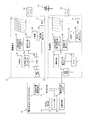
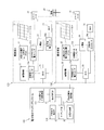
- the power transaction matching system 10 is a system that interchanges surplus power between a plurality of consumers who own a power generation device and a storage battery. As shown in FIG. Excess power is interchanged between the (first customer) 20 and the customer B (second customer) 30.
- the power transaction matching system 10 is configured to generate a plurality of demands for generating surplus power based on required power amount information input from a consumer A20 who needs to be supplied with power from outside during a predetermined time period.
- the optimal customer is matched from house B30.
- the power transaction matching system 10 performs power transmission control between the matched consumers (specifically, from the consumer B30 to the consumer A20) so that surplus power is supplied.
- the electronic terminals 27 and 37 are installed in the respective consumers A and B, respectively, and are PCs to which information on the required power amount and information on the surplus power amount are input.
- Personal computer personal computer
- tablet terminal smartphone
- mobile phone etc.
- the solid lines connecting the components shown in FIG. 1 indicate the flow of information such as data, and the alternate long and short dash lines indicate the flow of electricity.
- the configuration of the power transaction matching system 10 of the present embodiment will be described in detail later.
- the power transaction matching system 10 of the present embodiment is connected to an electronic terminal 27 owned by a consumer A20 who needs power in a predetermined time zone.
- the customer A20 inputs information related to the amount of electric power (necessary electric energy) expected to be required in a predetermined time zone to the electric power transaction matching system 10 via the electronic terminal 27.
- the consumer A 20 includes a solar panel (power generation device) 21, a solar power generation power conversion device (PCS) 22, a power generation power sensor 22 a, a power storage device (storage battery) 23, and stored power.
- Power sensor 23a load 24, load power sensor 24a, distribution board 25, EMS (Energy Management System) 26, electronic terminal 27, and smart meter 28.
- the solar panel (power generation device) 21 is a device that generates electricity using the photovoltaic effect using the light energy of sunlight, and is installed on the roof or the like of the consumer A20. And the electric power generation amount in the solar panel 21 can be estimated based on the information regarding the sunshine time of a weather forecast.
- a photovoltaic power generation converter (PCS (Power Conditioning System)) 22 is connected to a solar panel 21 and converts a direct current generated in the solar panel 21 into an alternating current.
- the generated power sensor 22 a is connected to the solar power converter 22 and measures the amount of power generated by the solar panel 21.
- the generated power sensor 22 a transmits the measurement result (power generation amount) to the EMS 26.
- the power storage device (storage battery) 23 is provided to temporarily store surplus power that cannot be consumed by the load 24 among the power generated by the solar panel 21. Thereby, even when the amount of power consumed by the load 24 is small during the daytime when power is generated by the solar panel 21, it is possible to save the generated power by storing the surplus power in the power storage device 23. Can be eliminated.
- the stored power sensor 23 a is connected to the power storage device 23 and measures the amount of power stored in the power storage device 23. Then, the power sensor 23a for stored power transmits a measurement result (amount of stored power) to the EMS 26.
- the load 24 is a power consumer such as a home appliance such as an air conditioner or a refrigerator in a general home, equipment in a factory, an air conditioner, etc., and is generated by the power supplied from the system 40 or the solar panel 21. The electric power and the electric power stored in the power storage device 23 are consumed.
- the load power sensor 24 a is connected to the load 24 and measures the amount of power consumed by the load 24. Then, the load power sensor 24 a transmits the measurement result (power consumption amount) to the EMS 26.
- the distribution board 25 is connected to a power sensor for generated power 22 a, a power sensor for stored power 23 a, a power sensor for load 24 a, and a smart meter 28.
- the distribution board 25 supplies the power generated by the solar panel 21 and the power stored in the power storage device 23 to the load 24. Furthermore, the distribution board 25 supplies surplus power generated according to the time zone to the system 40 via the smart meter 28. Thereby, consumer A20 can sell surplus electric power to an electric power company.
- the EMS (Energy Management System) 26 is an energy management system provided to reduce power consumption in the consumer A20. As shown in FIG. 1, each sensor 22a, 23a, 24a is used. Connected with. The EMS 26 is connected to the electronic terminal 27. Furthermore, the EMS 26 efficiently supplies the load 24 with the power generated by the solar panel 21 and the amount of power stored in the power storage device 23 using the detection results received from the sensors 22a, 23a, and 24a. Thereby, the consumption of the electric power supplied from the system
- the electronic terminal 27 is a PC, a tablet terminal, a smartphone, or the like owned by the customer A20.
- zone is input into the electronic terminal 27 from consumer A20.
- the electronic terminal 27 is connected to the power transaction matching system 10 (required power amount information acquisition unit 11) via a communication line.
- the information regarding the required electric energy input via the electronic terminal 27 includes the electric energy (kwh) required by the customer A20 in a predetermined time zone, the date and time of the predetermined time zone, the location (address, etc.) of the customer A20. ), Information such as the desired price for the supplied power.
- the smart meter 28 measures the power generation amount of the solar panel 21 owned by the consumer A20, the power storage amount of the power storage device 23, and the power consumption amount of the load 24. And the smart meter 28 is connected with each sensor 22a, 23a, 24a via the distribution board 25, as shown in FIG. Furthermore, the smart meter 28 has a communication function, and transmits information on the amount of power generation, the amount of electricity stored, and the amount of power consumption in the consumer A20 to the power company.
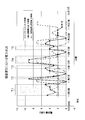
- the consumer A20 is described as a side that desires to supply surplus power from the outside during a predetermined time period. For this reason, in the consumer A20, it is assumed that the amount of power consumed by the load 24 is greater than the sum of the power generated by the solar panel 21 and the amount of power stored in the power storage device 23 in a predetermined time period. That is, in the customer A20, as shown in FIG. 2, it is predicted that the estimated values of the power generation amount (solid line), the storage amount (one-dot chain line), and the power consumption amount (dotted line) at a predetermined date and time will fluctuate.
- the horizontal axis indicates the date and time
- the vertical axis indicates the electric energy (kwh)
- the temporal transition of the electric energy consumption, the electric energy generation amount, and the electric energy storage amount of the power storage device in the consumer A20 is shown.
- the power generation amount (solid line) in the graph of FIG. 2 shows the transition of the estimated value of the power generation amount by the solar panel 21 using the information of the weather forecast (sunshine hours).
- the amount of electricity stored indicates the transition of the estimated value of the amount of electricity stored in the electricity storage device 23 using the current amount of electricity stored in the electricity storage device 23 and the estimated value of the power generation amount.
- power consumption (dotted line) has shown transition of the estimated value of power consumption in consumer A20 using transition information of past power consumption, such as a lifestyle pattern of consumer A20.
- the consumer A20 may input the demand condition via the electronic terminal 27 so that the surplus power is supplied from the other consumer B30 in these time periods t1 to t5.
- the power transaction matching system 10 of the present embodiment is connected to an electronic terminal 37 owned by a customer B30 that is estimated to generate surplus power in a predetermined time zone.
- the consumer B30 inputs information on the surplus power amount that is expected to be generated in a predetermined time zone to the power transaction matching system 10 via the electronic terminal 37.
- the consumer B 30 includes a solar panel (power generation device) 31, a solar power generation power conversion device (PCS) 32, a power generation power sensor 32 a, a power storage device (storage battery) 33, and stored power.
- the solar panel (power generation apparatus) 31 is an apparatus that generates electricity using the photovoltaic effect using the light energy of sunlight, and is a roof of the consumer B30. Etc. And the electric power generation amount in the solar panel 31 can be estimated based on the information regarding the sunshine time of a weather forecast.
- a photovoltaic power generation converter (PCS (Power Conditioning System)) 32 is connected to a solar panel 31 and converts a direct current generated in the solar panel 31 into an alternating current.
- PCS Power Conditioning System
- the generated power sensor 32 a is connected to the photovoltaic power converter 32 and measures the amount of power generated by the solar panel 31. Then, the generated power sensor 32a transmits the measurement result (power generation amount) to the EMS 36.
- the power storage device (storage battery) 33 is provided to temporarily store surplus power that cannot be consumed by the load 34 among the power generated by the solar panel 31. Thereby, even when the amount of power consumed by the load 34 is small during the daytime when power is generated by the solar panel 31, it is possible to save the generated power by storing the excess power in the power storage device 33. Can be eliminated.
- the stored power sensor 33 a is connected to the power storage device 33 and measures the amount of power stored in the power storage device 33. Then, the stored power sensor 33a transmits the measurement result (storage amount) to the EMS 36.
- the load 34 is a power consumer such as a home appliance such as an air conditioner or a refrigerator in a general household, equipment in a factory, an air conditioner, etc., and is generated by the power supplied from the system 40 and the solar panel 31. The electric power and the electric power stored in the power storage device 33 are consumed.
- the load power sensor 34 a is connected to the load 34 and measures the amount of power consumed by the load 34. Then, the load power sensor 34 a transmits a measurement result (power consumption amount) to the EMS 36.
- the distribution board 35 is connected to a power sensor 32a for generated power, a power sensor 33a for stored power, a power sensor 34a for load, and a smart meter 38.
- the distribution board 35 supplies the power generated in the solar panel 31 and the power stored in the power storage device 33 to the load 34. Further, the distribution board 35 supplies surplus power generated in the time zone to the system 40 via the smart meter 38. Thereby, consumer B30 can sell surplus power to the power company.
- the EMS (Energy Management System) 36 is an energy management system provided to reduce the power consumption in the customer B30. As shown in FIG. 1, each sensor 32a, 33a, 34a is used. Connected with. The EMS 36 is connected to the electronic terminal 37. Furthermore, the EMS 36 efficiently supplies the load 34 with the power generated by the solar panel 31 and the amount of power stored in the power storage device 33 using the detection results received from the sensors 32a, 33a, and 34a. Thereby, the consumption of the electric power supplied from the system
- the electronic terminal 37 is a PC, a tablet terminal, a smartphone, or the like owned by the customer B30.
- zone is input into the electronic terminal 37 from the consumer B30.
- the electronic terminal 37 is connected with the electric power transaction matching system 10 (customer information acquisition part 12) via the communication line.
- the information regarding the surplus power amount input via the electronic terminal 37 includes surplus power amount (kwh) estimated that the customer B30 can be supplied in a predetermined time zone, the date and time of the predetermined time zone, the customer B30's Information on location (address, etc.), desired price for supplied power, etc. is included.
- the smart meter 38 measures the power generation amount of the solar panel 31 owned by the customer B30, the power storage amount of the power storage device 33, and the power consumption amount of the load 34.
- the smart meter 38 is connected to the sensors 32a, 33a, and 34a via the distribution board 35 as shown in FIG.
- the smart meter 38 has a communication function, and transmits information on the amount of power generation, the amount of electricity stored, and the amount of power consumption in the customer B30 to the power company.
- the customer B30 is described as a side that supplies surplus power to the outside in a predetermined time zone. For this reason, in the consumer B30, the sum of the power generated by the solar panel 31 and the amount of power stored in the power storage device 33 is greater than the amount of power consumed by the load 34 in a predetermined time period. That is, in the customer B30, as shown in FIG. 3, it is predicted that the estimated values of the power generation amount (solid line), the storage amount (one-dot chain line), and the power consumption amount (dotted line) at a predetermined date and time will fluctuate.
- the horizontal axis indicates the date and time
- the vertical axis indicates the electric energy (kwh)
- the time transition of the electric energy consumption, the electric energy generation amount, and the electric energy storage amount of the power storage device in the customer B30 is shown.
- the power generation amount (solid line) in the graph of FIG. 3 shows the transition of the estimated value of the power generation amount by the solar panel 31 using the information on the weather forecast (sunshine hours).
- the amount of electricity stored indicates the transition of the estimated value of the amount of electricity stored in the electricity storage device 33 using the current amount of electricity stored in the electricity storage device 33 and the estimated value of the power generation amount.
- power consumption (dotted line) has shown transition of the estimated value of power consumption in consumer B30 using transition information of past power consumption, such as a lifestyle pattern of consumer B30.
- the consumer B30 may input the supply condition via the electronic terminal 37 so as to supply surplus power to the other consumer A20 in these time periods T1 to T5.
- the power transaction matching system 10 of this embodiment is a system for accommodating surplus power generated in the consumer B30 to the consumer A20 among a plurality of consumers.
- the power transaction matching system 10 includes a required power amount information acquisition unit 11, a customer information acquisition unit 12, a condition storage unit (storage unit) 13, a surplus power estimation unit 14, a matching unit 15, And a power transmission control unit 16.
- the required power amount information acquisition unit 11 acquires information about the required power amount from the consumer A 20 via the electronic terminal 27.
- the information on the required power amount input from the customer A20 is the amount of power (kwh) that the customer A20 needs in a predetermined time zone, the date and time of the predetermined time zone, the customer A20 Information such as the location (address, etc.) and the desired price for the supplied power is included (see FIG. 6). That is, the required power amount information acquisition unit 11 acquires the power demand condition required by the customer A20.
- the customer information acquisition unit 12 acquires information on the surplus power amount from the customer B 30 via the electronic terminal 37.
- the information on the surplus power input from the consumer B30 is the surplus power (kwh) estimated that the consumer B30 can be supplied in a predetermined time zone, the date and time of the predetermined time zone, Information such as the location (address, etc.) of the customer B30 and the desired price for the supplied power is included (see FIG. 7). That is, the consumer information acquisition unit 12 acquires the supply condition of surplus power that can be supplied by the consumer B30.
- the condition storage unit (storage unit) 13 is connected to the required power amount information acquisition unit 11 and the customer information acquisition unit 12. And the condition memory
- the surplus power estimation unit 14 is connected to the condition storage unit 13 as shown in FIG. The surplus power estimation unit 14 then generates surplus power in a predetermined time period based on the information on the power generation amount, power storage amount, and power consumption amount of the customer B30 included in the surplus power supply conditions stored in the condition storage unit 13. Estimate the amount.
- the surplus power estimation unit 14 obtains an estimated value of the surplus power from the surplus power supply condition input by the customer B30.
- the surplus power estimating unit 14 can use the input estimated value as it is.
- the matching unit 15 refers to the power demand condition of the consumer A20 and the surplus power supply condition of the consumer B30, and detects a combination that satisfies the mutual condition.
- the combination of the customer A20 and the customer B30 detected by the matching unit 15 is not limited to one set, and when there are a plurality of combinations that satisfy the condition, a combination of a plurality of consumers is detected as a candidate. May be. Then, when there are a plurality of combinations that satisfy the condition, the matching unit 15 narrows down the final combinations by adding conditions such as consideration for surplus power supply and loss during power transmission, for example.
- the power transmission control unit 16 transmits surplus power between a plurality of consumers based on the combination of the customer A20 and the customer B30 detected by the matching unit 15. Specifically, the power transmission control unit 16 supplies electric power to the consumer A20 that needs electric power from the consumer B30 in which surplus electric power is generated at a predetermined time period. Thereby, the consumer A does not need to buy electric power from the electric power company through the system 40 by receiving the supply of surplus power from the consumer B30 in the predetermined time zone. For this reason, the electricity bill of the consumer A20 can be reduced depending on the price of surplus power. And consumer B30 can utilize effectively the surplus electric power which was thrown away conventionally among a plurality of consumers.
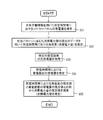
- step S11 demand information such as a required power amount, a required date and time, and a consideration for receiving supply of surplus power is input by the consumer A20 via the electronic terminal 27.
- step S11 demand information such as a required power amount, a required date and time, and a consideration for receiving supply of surplus power is input by the consumer A20 via the electronic terminal 27.
- the required power amount information acquisition unit 11 acquires the demand information input by the customer A20.
- the customer B30 inputs supply information regarding surplus power (the storage amount of the storage battery, the date and time when surplus power can be supplied, the desired price of surplus power, etc.) via the electronic terminal 37.
- the customer information acquisition unit 12 acquires supply information input by the customer B30.
- step S13 the demand condition and the supply condition that are input from the customer A20 and the customer B30 in step S11 and step S12 and acquired in the required power amount information acquisition unit 11 and the customer information acquisition unit 12 are the conditions. It is stored in the storage unit 13.
- step S14 the demand condition stored in the condition storage unit 13 is compared with the supply condition, and a combination of the consumer A20 and the consumer B30 that match (match) the conditions is detected. If there is a combination that matches the conditions, the process proceeds to step S15. On the other hand, if there is no combination that matches the condition, the process proceeds to step S16.
- step S15 surplus power is supplied from the consumer B30 to the consumer A20 at a predetermined time zone based on the matched combination.
- the supply of surplus power from the consumer B30 to the consumer A20 is performed via the smart meters 28 and 38.
- step S16 the information is updated by deleting the demand condition of the customer A20 and the supply condition of the customer B30 constituting the matched combination from the condition storage unit 13.
- the condition storage unit 13 is in a state where only the conditions of a plurality of customers for which matching has not yet been established are stored.
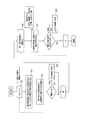
- step S21 the supply conditions of the plurality of consumers B30 stored in the condition storage unit 13 are sequentially checked from the first line with respect to the demand conditions input by the consumer A20.
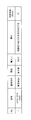
- the condition storage unit 13 stores the supply conditions of a plurality of consumers B shown in FIG. 7 together with the demand conditions of the consumer A20 shown in FIG.
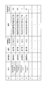
- the demand conditions of customer A shown in FIG. 6 include the required date and time of surplus power, the name of the registrant (name, company name, facility name, etc. of customer A), attribute (user side), required power (estimated value) ), Location (address, etc.), desired unit price (reward for surplus power), and the like.
- the supply conditions of the plurality of consumers B1 to B4 shown in FIG. 7 include the supply date and time of surplus power, the name of the registrant (name of the customer B, company name, facility name, etc.), attributes (lender side), surplus power Amount (estimated value), location (address, etc.), desired unit price (reward for surplus power), etc. are included.
- step S22 the supply conditions of the plurality of consumers B1 to B4 shown in FIG. 7 are read one by one.
- step S23 it is confirmed whether the read supply conditions of the consumers B1 to B4 are consistent with the demand conditions of the consumer A.
- step S24 if the conditions match, the process proceeds to step S25, and the supply conditions of the consumers B1 to B4 are added as transaction candidates (see FIG. 8). And the process after step S21 is repeatedly performed until it verifies whether it matches about all the conditions preserve
- step S24 the process returns to step S21 until it is verified whether or not all the conditions stored in the condition storage unit 13 match, and the supply conditions of the other consumers B1 to B4 Is read out to confirm whether it matches.
- the process returns to step S21 until it is verified whether or not all the conditions stored in the condition storage unit 13 match, and the supply conditions of the other consumers B1 to B4 Is read out to confirm whether it matches.
- the date and time (12:00) and surplus power (55.0 kwh) of customer B1 do not match.
- the address is different from the customer A in the X-chome, the Y-chome, and the Z-chome, it is assumed that the power transmission loss amount described below is also large.
- step S26 the supply conditions of the plurality of consumers B3 and B4 included in the list stored as transaction candidates shown in FIG.
- step S27 the supply condition of the transaction candidate is read, and profit is calculated when the Nth candidate is traded. Specifically, the profit on the customer B3, B4 side is calculated using the following profit calculation formula (1).
- Profit Unit price x (Transaction power amount-Transmission loss amount) (1)
- the unit price means a consideration when supplying surplus power set by the consumers B3 and B4.
- the consumer B3 is ⁇ 15 / kwh
- the consumer B4 is ⁇ 50 / kwh is set.
- the power transmission loss amount means a loss that occurs when surplus power is transmitted to the customer A. Mainly, the power transmission loss increases as the distance from the power transmission source to the power transmission destination increases. Therefore, the estimated value of the power transmission loss amount is calculated based on the distance to the consumer A. For this reason, from the location information included in the supply conditions, it is expected that the customers B1 and B2 that are far from the customer A shown in FIG.
- step S28 the consumers B3 and B4 on the supply side that match the conditions are compared with the calculated profit.
- step S29 the customer B4 having the largest calculated profit is set as the final candidate. That is, it is estimated that the consumers B3 and B4 in the same Z-chome have almost the same level of power transmission loss up to the customer A.
- the desired unit price is ⁇ 15 / kwh for the customer B3 and ⁇ 50 / kwh for the customer B4, but both are consistent with the desired unit price condition of the customer A.
- step S28 * S29 a comparison of the calculation profit is implemented about all the transaction candidates, and a process is complete
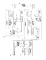
- the power transaction matching system 10 of the first embodiment is not provided on the side of the customer A120 and the customer B130. Is different. Since the basic configuration excluding the above points is the same as that of the first embodiment, the same reference numerals are given to the configurations having the same functions as those of the first embodiment, and detailed description thereof is omitted. .
- the required power amount information acquisition unit 111 automatically receives information on the required power amount (required power amount, date / time, location, consideration, etc.) from the EMS 26 on the customer A 120 side. Receive. And the consumer information acquisition part 112 receives automatically the information regarding surplus electric power supply conditions (excess electric energy, a date, a place, consideration, etc.) from EMS36 by the side of the consumer B130.
- the demand condition estimated in the EMS 26 is used instead of using the information regarding the required power amount input by the consumer A120.
- the supply condition estimated in the EMS 36 is used instead of using the information regarding the surplus power input by the consumer B130.
- EMS36 estimates the electric power generation amount by the solar panel 31 in a predetermined time slot
- the EMS 36 estimates the power storage amount of the power storage device 33 in a predetermined time zone using the current power storage amount of the power storage device 33 and the estimated value of the power generation amount.
- the EMS 36 estimates the power consumption that varies depending on the lifestyle pattern of the consumer B30.
- the surplus power estimation unit 114 uses the sum of the estimated value of the power generation amount of the solar panel 31 and the estimated value of the power storage amount of the power storage device 33 stored in the condition storage unit 13 to change the power consumption depending on the lifestyle pattern of the consumer B30.
- the surplus power amount in the consumer B is estimated by subtracting the estimated value of the amount.
- the surplus electric power estimation part 114 can estimate the surplus electric energy which can be supplied to the other consumer A20 from the consumer B30 in the predetermined time slot
- step S32 the amount of power consumption in a predetermined time zone is estimated using data on the amount of load (power consumption) that changes according to the past life pattern of the consumer B130.
- step S33 the current charge / discharge amount of the power storage device is acquired.
- step S34 the power storage amount of the power storage device in a predetermined time zone is designated based on the current charge / discharge amount information of the power storage device.
- step S35 the estimated value of the load amount (power consumption amount) is subtracted from the sum of the estimated power generation amount and the storage amount of the consumer B 130 in the predetermined time period. Thereby, the surplus electric energy in the predetermined time slot
- power demand information is input from the consumer A 20 via the electronic terminal 27, and surplus power supply information is automatically acquired from the EMS 36 from the consumer B 130. May be. That is, you may combine the structure of the consumer A20 of the said Embodiment 1, and the structure of the consumer B130 of the said Embodiment 2.
- FIG. 12 shows that is, you may combine the structure of the consumer A20 of the said Embodiment 1, and the structure of the consumer B130 of the said Embodiment 2.
- power demand information is automatically acquired from the consumer A120 from the EMS 26 and surplus power supply information is input from the consumer B30 via the electronic terminal 37. It may be. That is, the configuration of the customer B30 in the first embodiment and the configuration of the customer A120 in the second embodiment may be combined.
- the electronic terminals 27 and 37 acquire information on the power generation amount, the power storage amount, and the power consumption amount in the customer A20 and the customer B30 via the EMSs 26 and 36, respectively. And explained.
- the present invention is not limited to this.
- the electronic terminal may acquire information on the amount of power generation, the amount of electricity stored, and the amount of power consumption in the customer A and the customer B using the communication functions of the smart meters installed in the consumers A and B, respectively. .
- solar panels (solar power generation devices) 21 and 31 are used as power generation devices owned by a plurality of consumers A20, consumers B30, customers A120, and consumers B130.
- the example used was explained.
- the present invention is not limited to this.
- the power transaction matching system of the present invention has an effect that it is possible to efficiently exchange surplus power among a plurality of consumers who own a power generation device and a storage battery. It can be widely applied in communities including other consumers.
Landscapes
- Engineering & Computer Science (AREA)
- Business, Economics & Management (AREA)
- Power Engineering (AREA)
- Economics (AREA)
- Health & Medical Sciences (AREA)
- Finance (AREA)
- Physics & Mathematics (AREA)
- Accounting & Taxation (AREA)
- Theoretical Computer Science (AREA)
- Marketing (AREA)
- General Physics & Mathematics (AREA)
- Strategic Management (AREA)
- General Business, Economics & Management (AREA)
- Water Supply & Treatment (AREA)
- Tourism & Hospitality (AREA)
- Primary Health Care (AREA)
- Human Resources & Organizations (AREA)
- General Health & Medical Sciences (AREA)
- Public Health (AREA)
- Development Economics (AREA)
- Technology Law (AREA)
- Management, Administration, Business Operations System, And Electronic Commerce (AREA)
- Supply And Distribution Of Alternating Current (AREA)
- Remote Monitoring And Control Of Power-Distribution Networks (AREA)
- Charge And Discharge Circuits For Batteries Or The Like (AREA)
Abstract
電力取引マッチングシステム(10)は、必要電力量情報取得部(11)、需要家情報取得部(12)、余剰電力推定部(14)、マッチング部(15)を備えている。余剰電力推定部(14)は、需要家情報取得部(12)において取得された需要家B(30)の所定時間帯における発電量および蓄電量、消費電力量に基づいて、供給可能な余剰電力量を推定する。マッチング部(15)は、余剰電力推定部(14)において推定された需要家B(30)から供給可能な余剰電力量情報と、必要電力量情報取得部(11)において取得された需要家A(20)の必要電力量情報とを照合して、条件が整合する需要家同士の組合せを検出する。
Description
本発明は、電力取引マッチングシステム、電力取引マッチング方法および電力取引マッチングプログラムに関する。
近年、再生可能エネルギーを利用して発電する発電電力装置(例えば、太陽光発電装置)が活用されている。わが国においては、余剰電力買い取り制度が制定されているため、太陽光発電装置や風力発電電装置等で発電された電力を電力会社に売ることができる。
一方、発電した電力を電力会社に売ることができない場合がある。例えば、電力会社が買い取り可能な所定の電力量を超えた場合(以下:出力抑制と示す。)等である。このため、需要家は、売却できなかった電力を一時貯めることが可能な蓄電池を用いることがある。
一方、発電した電力を電力会社に売ることができない場合がある。例えば、電力会社が買い取り可能な所定の電力量を超えた場合(以下:出力抑制と示す。)等である。このため、需要家は、売却できなかった電力を一時貯めることが可能な蓄電池を用いることがある。
しかしながら、蓄電池の残電池容量に対して、発電装置で発電される電力量が多い場合には、発電装置において発電された電力を捨てなければならない場合がある。
例えば、特許文献1には、買い電力入札の電力量、時間帯および価格に関する情報と、売り電力入札の電力量、時間帯および価格に関する情報とをマッチングして、複数の需要家間において、余剰電力を融通し合うことが可能な電力取引仲介システムについて開示されている。
例えば、特許文献1には、買い電力入札の電力量、時間帯および価格に関する情報と、売り電力入札の電力量、時間帯および価格に関する情報とをマッチングして、複数の需要家間において、余剰電力を融通し合うことが可能な電力取引仲介システムについて開示されている。
しかしながら、上記従来の電力取引仲介システムでは、以下に示すような問題点を有している。
すなわち、上記公報に開示されたシステムでは、時間単位の長い電力入札に対して複数の電力入札の組合せをマッチングすることで、発電会社の入札の不利を解消して取引量を増やしている。
すなわち、上記公報に開示されたシステムでは、時間単位の長い電力入札に対して複数の電力入札の組合せをマッチングすることで、発電会社の入札の不利を解消して取引量を増やしている。
しかし、このシステムでは、太陽光発電等の自然エネルギーによって発電した電力をそのまま他の需要家へ融通する構成となっている。このため、需要家において、発電した電力のうちの余剰分(余剰電力)を蓄えることが可能な蓄電池を備えている場合について何ら考慮されていない。
本発明の課題は、発電装置と蓄電池とを所有する複数の需要家間において効率的に余剰電力を融通し合うことが可能な電力取引マッチングシステム、電力取引マッチング方法および電力取引マッチングプログラムを提供することにある。
本発明の課題は、発電装置と蓄電池とを所有する複数の需要家間において効率的に余剰電力を融通し合うことが可能な電力取引マッチングシステム、電力取引マッチング方法および電力取引マッチングプログラムを提供することにある。
(課題を解決するための手段)
第1の発明に係る電力取引マッチングシステムは、発電装置と蓄電池とを所有する複数の需要家間において、お互いの余剰電力を融通し合うための電力取引マッチングシステムであって、必要電力量情報取得部と、需要家情報取得部と、余剰電力推定部と、マッチング部と、を備えている。必要電力量情報取得部は、第1の需要家が所定時間帯に必要とする電力量に関する情報を取得する。需要家情報取得部は、第2の需要家が所有する発電装置および蓄電池、第2の需要家の消費電力量に関する情報を取得する。余剰電力推定部は、需要家情報取得部において取得された第2の需要家の所定時間帯における発電装置の発電量および蓄電池の蓄電量、消費電力量に関する情報に基づいて、第2の需要家において供給可能な余剰電力量を推定する。マッチング部は、余剰電力推定部において推定された第2の需要家から供給可能な余剰電力量と、必要電力量情報取得部において取得された第1の需要家の必要電力量に関する情報とを照合して、取引が成立する第1の需要家と第2の需要家の組合せを検出する。
第1の発明に係る電力取引マッチングシステムは、発電装置と蓄電池とを所有する複数の需要家間において、お互いの余剰電力を融通し合うための電力取引マッチングシステムであって、必要電力量情報取得部と、需要家情報取得部と、余剰電力推定部と、マッチング部と、を備えている。必要電力量情報取得部は、第1の需要家が所定時間帯に必要とする電力量に関する情報を取得する。需要家情報取得部は、第2の需要家が所有する発電装置および蓄電池、第2の需要家の消費電力量に関する情報を取得する。余剰電力推定部は、需要家情報取得部において取得された第2の需要家の所定時間帯における発電装置の発電量および蓄電池の蓄電量、消費電力量に関する情報に基づいて、第2の需要家において供給可能な余剰電力量を推定する。マッチング部は、余剰電力推定部において推定された第2の需要家から供給可能な余剰電力量と、必要電力量情報取得部において取得された第1の需要家の必要電力量に関する情報とを照合して、取引が成立する第1の需要家と第2の需要家の組合せを検出する。
ここでは、発電装置と蓄電池とを所有する複数の需要家間において、お互いの余剰電力を融通し合うためのシステムを構成している。具体的には、所定時間帯に外部からの電力供給を必要とする第1の需要家と、当該所定時間帯に発電装置によって発電された電力量、蓄電池に蓄えられた蓄電量、消費電力量に基づいて余剰電力が発生することが想定される第2の需要家とをマッチングする。
なお、第1の需要家および第2の需要家が所有する発電装置としては、例えば、太陽光発電装置、風力発電装置、地熱発電装置等が含まれる。
また、第1の需要家に対して余剰電力を供給する第2の需要家は、単数であってもよいし複数であってもよい。
ここで、必要電力量情報取得部によって取得される必要電力量情報は、第1の需要家によって、外部から供給を必要とする電力量、供給日時等の需要条件が直接入力されてもよい。あるいは、必要電力量情報は、第1の需要家の発電装置の発電量、蓄電池の蓄電量、生活パターンや消費電力量の推移等の過去のデータに基づいて自動的に取得されてもよい。
また、第1の需要家に対して余剰電力を供給する第2の需要家は、単数であってもよいし複数であってもよい。
ここで、必要電力量情報取得部によって取得される必要電力量情報は、第1の需要家によって、外部から供給を必要とする電力量、供給日時等の需要条件が直接入力されてもよい。あるいは、必要電力量情報は、第1の需要家の発電装置の発電量、蓄電池の蓄電量、生活パターンや消費電力量の推移等の過去のデータに基づいて自動的に取得されてもよい。
また、需要家情報取得部によって取得される需要家情報は、余剰電力が発生することが想定される第2の需要家から供給可能条件として直接入力されてもよい。あるいは、需要家情報は、所定時間帯における天気予報等の情報に基づいて、第2の需要家が所有する発電装置の発電量、蓄電池の蓄電量の推定値として自動的に取得されてもよい。
なお、必要電力量情報取得部および需要家情報取得部において取得された各種情報は、システム内部に設けられた記憶部に保存されてもよいし、外部のサーバ等に保存されてもよい。
なお、必要電力量情報取得部および需要家情報取得部において取得された各種情報は、システム内部に設けられた記憶部に保存されてもよいし、外部のサーバ等に保存されてもよい。
余剰電力推定部は、需要家情報取得部において取得された各種情報に基づいて、所定時間帯における第2の需要家で発生する余剰電力量を推定する。具体的には、余剰電力推定部は、所定時間帯における天気予報(日照時間、風速等)等に基づいて、発電装置による予想発電量を算出する。そして、余剰電力推定部は、現在の蓄電池の蓄電量を検出して、所定時間帯における蓄電池の蓄電量を推定する。さらに、余剰出力推定部は、予想発電量、蓄電池の蓄電量から、第2の需要家の生活パターンや過去のデータ等に基づいて算出される所定時間帯における予想消費電力量を差し引く。これにより、余剰電力推定部は、第2の需要家において発生する余剰電力量を推定する。
マッチング部は、必要電力量情報取得部において取得された需要条件と、余剰電力推定部において推定された第2の需要家における余剰電力量とその供給条件等を照合して、所定時間帯において余剰電力を必要とする第1の需要家と、当該時間帯に余剰電力が発生する第2の需要家との組合せを検出する。
なお、マッチング部において検出される第1の需要家と第2の需要家の組み合わせは、1つであってもよいし、複数であってもよい。
なお、マッチング部において検出される第1の需要家と第2の需要家の組み合わせは、1つであってもよいし、複数であってもよい。
これにより、第1の需要家において電力を必要とする所定時間帯に、第2の需要家において余剰電力が発生する場合には、第1の需要家における需要条件と第2の需要家における供給可能条件等を照合して、適切な組合せをマッチングすることができる。
よって、従来は第2の需要家において廃棄されていた余剰電力を、複数の需要家間において有効に活用することができる。この結果、発電装置と蓄電池とを所有する複数の需要家間において効率的に余剰電力を融通し合うことができる。
よって、従来は第2の需要家において廃棄されていた余剰電力を、複数の需要家間において有効に活用することができる。この結果、発電装置と蓄電池とを所有する複数の需要家間において効率的に余剰電力を融通し合うことができる。
第2の発明に係る電力取引マッチングシステムは、第1の発明に係る電力取引マッチングシステムであって、マッチング部において検出された第1の需要家と第2の需要家の組合せに基づいて、供給元の第2の需要家から供給先の第1の需要家に対して、余剰電力を送電する送電制御部を、さらに備えている。
ここでは、送電制御部が、マッチング部において検出された第1の需要家と第2の需要家の組み合わせを基づいて、供給元となる第2の需要家から供給先となる第1の需要家に対して、余剰電力を送電する。
ここでは、送電制御部が、マッチング部において検出された第1の需要家と第2の需要家の組み合わせを基づいて、供給元となる第2の需要家から供給先となる第1の需要家に対して、余剰電力を送電する。
ここで、マッチング部において検出された第1の需要家と第2の需要家の組み合わせが複数ある場合には、送電制御部が、例えば、第2の需要家の供給可能条件に含まれる電力量、対価、送電時に生じるロス等に基づいて、最適な組み合わせを選択して、送電すればよい。
これにより、発電装置と蓄電池とを所有する複数の需要家間において効率的に余剰電力を融通し合うことができる。
これにより、発電装置と蓄電池とを所有する複数の需要家間において効率的に余剰電力を融通し合うことができる。
第3の発明に係る電力取引マッチングシステムは、第1または第2の発明に係る電力取引マッチングシステムであって、必要電力量情報取得部において取得された情報、需要家情報取得部において取得された情報を保存する記憶部を、さらに備えている。
ここでは、必要電力量情報取得部において取得された情報、需要家情報取得部において取得された情報を、システム内に設けられた記憶部に保存する。
これにより、例えば、所定時間経過ごとに、記憶部に保存された各種情報を用いて、第1の需要家と第2の需要家とを組み合わせを検出して、電力融通のマッチングを行うことができる。
ここでは、必要電力量情報取得部において取得された情報、需要家情報取得部において取得された情報を、システム内に設けられた記憶部に保存する。
これにより、例えば、所定時間経過ごとに、記憶部に保存された各種情報を用いて、第1の需要家と第2の需要家とを組み合わせを検出して、電力融通のマッチングを行うことができる。
第4の発明に係る電力取引マッチングシステムは、第1から第3の発明のいずれか1つに係る電力取引マッチングシステムであって、余剰電力推定部は、天気予報に関する情報に基づいて、第2の需要家の所定時間帯における発電装置の発電量を推定する。
ここでは、余剰電力推定部による余剰電力の推定に、天気予報に関する情報を用いる。
これにより、例えば、発電装置が太陽光発電装置の場合には、天気予報の日照時間の情報を用いて、太陽光発電装置による発電量を予測することができる。また、例えば、発電装置が風力発電装置の場合には、天気予報の風速の情報を用いて、風力発電装置による発電量を予測することができる。
ここでは、余剰電力推定部による余剰電力の推定に、天気予報に関する情報を用いる。
これにより、例えば、発電装置が太陽光発電装置の場合には、天気予報の日照時間の情報を用いて、太陽光発電装置による発電量を予測することができる。また、例えば、発電装置が風力発電装置の場合には、天気予報の風速の情報を用いて、風力発電装置による発電量を予測することができる。
第5の発明に係る電力取引マッチングシステムは、第1から第4の発明のいずれか1つに係る電力取引マッチングシステムであって、余剰電力推定部は、過去の生活パターンに応じた消費電力量を記録したデータに基づいて、第2の需要家の所定時間帯における消費電力量を推定する。
ここでは、余剰電力推定部による余剰電力の推定に必要な消費電力量の推定に、第2の需要家の生活パターンに応じた消費電力量を記録したデータを用いる。
ここでは、余剰電力推定部による余剰電力の推定に必要な消費電力量の推定に、第2の需要家の生活パターンに応じた消費電力量を記録したデータを用いる。
これにより、例えば、第2の需要家が日中よりも夜間の消費電力量が多い生活パターンの場合には、太陽光発電装置による発電量が多く、消費電力量が少ない日中の時間帯に余剰電力が生じる可能性が高いことが分かる。よって、需要家ごとに余剰電力が生じやすい時間帯を検出して、消費電力量の推定精度を向上させることができる。
第6の発明に係る電力取引マッチングシステムは、第1から第5の発明のいずれか1つに係る電力取引マッチングシステムであって、余剰電力推定部は、現時点の蓄電池の蓄電量を取得して、第2の需要家の所定時間帯における蓄電池の蓄電量を推定する。
ここでは、余剰電力推定部による余剰電力の推定に、現在の蓄電池の蓄電量を用いる。
これにより、例えば、所定時間帯における第2の需要家の発電装置の発電量、消費電力量の推定値とともに、現在の蓄電池の蓄電量を用いて、所定時間帯に第1の需要家に対して供給可能な余剰電力量の推定を行うことができる。
ここでは、余剰電力推定部による余剰電力の推定に、現在の蓄電池の蓄電量を用いる。
これにより、例えば、所定時間帯における第2の需要家の発電装置の発電量、消費電力量の推定値とともに、現在の蓄電池の蓄電量を用いて、所定時間帯に第1の需要家に対して供給可能な余剰電力量の推定を行うことができる。
第7の発明に係る電力取引マッチングシステムは、第1から第6の発明のいずれか1つに係る電力取引マッチングシステムであって、必要電力量情報取得部は、第1の需要家によって入力された必要電力量に関する情報を取得する。
ここでは、第1の需要家によって入力された必要電力量に関する情報を、必要電力量取得部が取得する。
これにより、第1の需要家から直接入力された必要電力量の情報を用いて、余剰電力を供給可能な第2の需要家とのマッチングを行うことができる。
ここでは、第1の需要家によって入力された必要電力量に関する情報を、必要電力量取得部が取得する。
これにより、第1の需要家から直接入力された必要電力量の情報を用いて、余剰電力を供給可能な第2の需要家とのマッチングを行うことができる。
第8の発明に係る電力取引マッチングシステムは、第1から第7の発明のいずれか1つに係る電力取引マッチングシステムであって、必要電力量情報取得部は、第1の需要家が受け取りを希望する電力量、受取希望日時、時間帯、場所、電力の単価、対価のうち少なくとも1つを含む情報を取得する。
ここでは、必要電力量情報取得部において取得される各種情報は、第1の需要家が受け取りを希望する電力量、受取希望日時、時間帯、場所、電力の単価(¥/wh)、対価等の情報を含む。
これにより、第1の需要家において必要な電力量だけでなく、第2の需要家から余剰電力を受け取る希望日時、時間帯、第2の需要家の場所、余剰電力の単価、対価に関する情報を用いて、最適な第2の需要家とのマッチングを行うことができる。
これにより、第1の需要家において必要な電力量だけでなく、第2の需要家から余剰電力を受け取る希望日時、時間帯、第2の需要家の場所、余剰電力の単価、対価に関する情報を用いて、最適な第2の需要家とのマッチングを行うことができる。
第9の発明に係る電力取引マッチングシステムは、第1から第8の発明のいずれか1つに係る電力取引マッチングシステムであって、需要家情報取得部は、第2の需要家によって入力された発電装置および蓄電池に関する情報を取得する。
ここでは、余剰電力に関する情報として、発電装置および蓄電池に関する情報が、第2の需要家によって入力される。
ここでは、余剰電力に関する情報として、発電装置および蓄電池に関する情報が、第2の需要家によって入力される。
なお、入力される発電装置の情報としては、発電装置の種類、発電能力、天気予報に基づく推定発電量等が含まれる。また、入力される蓄電池の情報としては、現在の蓄電池の蓄電量、蓄電池の満充電容量等の情報が含まれる。
これにより、第2の需要家から直接入力された発電装置、蓄電池の情報を用いて、余剰電力の推定を行うことができる。
これにより、第2の需要家から直接入力された発電装置、蓄電池の情報を用いて、余剰電力の推定を行うことができる。
第10の発明に係る電力取引マッチングシステムは、第1から第9の発明のいずれか1つに係る電力取引マッチングシステムであって、マッチング部は、第1の需要家と取引が成立する第2の需要家が複数存在する場合には、第2の需要家から第1の需要家へ送電される電力の単価に基づいて、第1の需要家と第2の需要家の組合せを選択する。
ここでは、第1の需要家と取引が成立する第2の需要家が複数存在する場合の選択条件として、余剰電力の供給に対する単価(¥/wh)を用いる。
ここでは、第1の需要家と取引が成立する第2の需要家が複数存在する場合の選択条件として、余剰電力の供給に対する単価(¥/wh)を用いる。
なお、単価に関する情報は、余剰電力を供給する側の第2の需要家によって入力されてもよいし、複数の第2の需要家における余剰電力量の推移に基づいて自動的に設定された対価情報を用いてもよい。
これにより、例えば、第1の需要家が必要な電力量を供給可能な複数の第2の需要家のうち、最も安価な単価で余剰電力を供給してくれる第2の需要家を選択してマッチングすることができる。
これにより、例えば、第1の需要家が必要な電力量を供給可能な複数の第2の需要家のうち、最も安価な単価で余剰電力を供給してくれる第2の需要家を選択してマッチングすることができる。
第11の発明に係る電力取引マッチングシステムは、第1から第10の発明のいずれか1つに係る電力取引マッチングシステムであって、マッチング部は、第1の需要家と取引が成立する第2の需要家が複数存在する場合には、第1の需要家から第2の需要家へ送電する際の送電ロスの大きさに基づいて、第1の需要家と第2の需要家の組合せを選択する。
ここでは、第1の需要家と取引が成立する第2の需要家が複数存在する場合の選択条件として、余剰電力の送電時に生じるロスの大きさを用いる。
なお、余剰電力の送電時に生じるロスに関する情報は、余剰電力を供給する側の第2の需要家から第1の需要家までの距離、第1の需要家および第2の需要家の位置を含む地図情報等を用いてもよい。
これにより、例えば、第1の需要家が必要な電力量を供給可能な複数の第2の需要家のうち、最も送電ロスが少なく(距離が近い)余剰電力を供給してくれる第2の需要家を選択してマッチングすることができる。この結果、第2の需要家から供給される余剰電力を、第1の需要家が効率よく受け取ることができる。
なお、余剰電力の送電時に生じるロスに関する情報は、余剰電力を供給する側の第2の需要家から第1の需要家までの距離、第1の需要家および第2の需要家の位置を含む地図情報等を用いてもよい。
これにより、例えば、第1の需要家が必要な電力量を供給可能な複数の第2の需要家のうち、最も送電ロスが少なく(距離が近い)余剰電力を供給してくれる第2の需要家を選択してマッチングすることができる。この結果、第2の需要家から供給される余剰電力を、第1の需要家が効率よく受け取ることができる。
第12の発明に係る電力取引マッチング方法は、発電装置と蓄電池とを所有する複数の需要家間において、お互いの余剰電力を融通し合うための電力取引マッチング方法であって、必要電力量情報取得ステップと、需要家情報取得ステップと、余剰電力推定ステップと、マッチングステップと、を備えている。必要電力量情報取得ステップは、第1の需要家が所定時間帯に必要とする電力量に関する情報を取得する。需要家情報取得ステップは、第2の需要家が所有する発電装置および蓄電池、第2の需要家の消費電力量に関する情報を取得する。余剰電力推定ステップは、需要家情報取得ステップにおいて取得された第2の需要家の所定時間帯における発電装置の発電量および蓄電池の蓄電量、消費電力量に関する情報に基づいて、第2の需要家において供給可能な余剰電力量を推定する。マッチングステップは、余剰電力推定ステップにおいて推定された第2の需要家から供給可能な余剰電力量と、必要電力量情報取得ステップにおいて取得された第1の需要家の必要電力量に関する情報とを照合して、取引が成立する第1の需要家と第2の需要家の組合せを検出する。
ここでは、発電装置と蓄電池とを所有する複数の需要家間において、お互いの余剰電力を融通し合うためのステップを含む方法を構成している。具体的には、所定時間帯に外部からの電力供給を必要とする第1の需要家と、当該所定時間帯に発電装置によって発電された電力量、蓄電池に蓄えられた蓄電量、消費電力量に基づいて余剰電力が発生することが想定される第2の需要家とをマッチングする。
なお、第1の需要家および第2の需要家が所有する発電装置としては、例えば、太陽光発電装置、風力発電装置、地熱発電装置等が含まれる。
また、第1の需要家に対して余剰電力を供給する第2の需要家は、単数であってもよいし複数であってもよい。
ここで、必要電力量情報取得ステップによって取得される必要電力量情報は、第1の需要家によって、外部から供給を必要とする電力量、供給日時等の需要条件が直接入力されてもよい。あるいは、必要電力量情報は、第1の需要家の発電装置の発電量、蓄電池の蓄電量、生活パターンや消費電力量の推移等の過去のデータに基づいて自動的に取得されてもよい。
また、第1の需要家に対して余剰電力を供給する第2の需要家は、単数であってもよいし複数であってもよい。
ここで、必要電力量情報取得ステップによって取得される必要電力量情報は、第1の需要家によって、外部から供給を必要とする電力量、供給日時等の需要条件が直接入力されてもよい。あるいは、必要電力量情報は、第1の需要家の発電装置の発電量、蓄電池の蓄電量、生活パターンや消費電力量の推移等の過去のデータに基づいて自動的に取得されてもよい。
また、需要家情報取得ステップによって取得される需要家情報は、余剰電力が発生することが想定される第2の需要家から供給可能条件として直接入力されてもよい。あるいは、需要家情報は、所定時間帯における天気予報等の情報に基づいて、第2の需要家が所有する発電装置の発電量、蓄電池の蓄電量の推定値として自動的に取得されてもよい。
なお、必要電力量情報取得ステップおよび需要家情報取得ステップにおいて取得された各種情報は、システム内部に設けられた記憶部に保存されてもよいし、外部のサーバ等に保存されてもよい。
なお、必要電力量情報取得ステップおよび需要家情報取得ステップにおいて取得された各種情報は、システム内部に設けられた記憶部に保存されてもよいし、外部のサーバ等に保存されてもよい。
さらに、余剰電力推定ステップは、需要家情報取得ステップにおいて取得された各種情報に基づいて、所定時間帯における第2の需要家で発生する余剰電力量を推定する。具体的には、余剰電力推定ステップは、所定時間帯における天気予報(日照時間、風速等)等に基づいて、発電装置による予想発電量を算出する。そして、余剰電力推定ステップは、現在の蓄電池の蓄電量を検出して、所定時間帯における蓄電池の蓄電量を推定する。さらに、余剰出力推定ステップは、予想発電量、蓄電池の蓄電量から、第2の需要家の生活パターンや過去のデータ等に基づいて算出される所定時間帯における予想消費電力量を差し引く。これにより、余剰電力推定ステップは、第2の需要家において発生する余剰電力量を推定する。
そして、マッチングステップは、必要電力量情報取得ステップにおいて取得された需要条件と、余剰電力推定ステップにおいて推定された第2の需要家における余剰電力量とその供給条件等を照合して、所定時間帯において余剰電力を必要とする第1の需要家と、当該時間帯に余剰電力が発生する第2の需要家との組合せを検出する。
なお、マッチングステップにおいて検出される第1の需要家と第2の需要家の組み合わせは、1つであってもよいし、複数であってもよい。
なお、マッチングステップにおいて検出される第1の需要家と第2の需要家の組み合わせは、1つであってもよいし、複数であってもよい。
これにより、第1の需要家において電力を必要とする所定時間帯に、第2の需要家において余剰電力が発生する場合には、第1の需要家における需要条件と第2の需要家における供給可能条件等を照合して、適切な組合せをマッチングすることができる。
よって、従来は第2の需要家において廃棄されていた余剰電力を、複数の需要家間において有効に活用することができる。この結果、発電装置と蓄電池とを所有する複数の需要家間において効率的に余剰電力を融通し合うことができる。
よって、従来は第2の需要家において廃棄されていた余剰電力を、複数の需要家間において有効に活用することができる。この結果、発電装置と蓄電池とを所有する複数の需要家間において効率的に余剰電力を融通し合うことができる。
第13の発明に係る電力取引マッチングプログラムは、発電装置と蓄電池とを所有する複数の需要家間において、お互いの余剰電力を融通し合うための電力取引マッチングプログラムであって、必要電力量情報取得ステップと、需要家情報取得ステップと、余剰電力推定ステップと、マッチングステップと、を備えている電力取引マッチング方法をコンピュータに実行させる。必要電力量情報取得ステップは、第1の需要家が所定時間帯に必要とする電力量に関する情報を取得する。需要家情報取得ステップは、第2の需要家が所有する発電装置および蓄電池、第2の需要家の消費電力量に関する情報を取得する。余剰電力推定ステップは、需要家情報取得ステップにおいて取得された第2の需要家の所定時間帯における発電装置の発電量および蓄電池の蓄電量、消費電力量に関する情報に基づいて、第2の需要家において供給可能な余剰電力量を推定する。マッチングステップは、余剰電力推定ステップにおいて推定された第2の需要家から供給可能な余剰電力量と、必要電力量情報取得ステップにおいて取得された第1の需要家の必要電力量に関する情報とを照合して、取引が成立する第1の需要家と第2の需要家の組合せを検出する。
ここでは、発電装置と蓄電池とを所有する複数の需要家間において、お互いの余剰電力を融通し合うためのステップを含む方法をコンピュータに実行させるプログラムを構成している。具体的には、所定時間帯に外部からの電力供給を必要とする第1の需要家と、当該所定時間帯に発電装置によって発電された電力量、蓄電池に蓄えられた蓄電量、消費電力量に基づいて余剰電力が発生することが想定される第2の需要家とをマッチングする。
なお、第1の需要家および第2の需要家が所有する発電装置としては、例えば、太陽光発電装置、風力発電装置、地熱発電装置等が含まれる。
また、第1の需要家に対して余剰電力を供給する第2の需要家は、単数であってもよいし複数であってもよい。
ここで、必要電力量情報取得ステップによって取得される必要電力量情報は、第1の需要家によって、外部から供給を必要とする電力量、供給日時等の需要条件が直接入力されてもよい。あるいは、必要電力量情報は、第1の需要家の発電装置の発電量、蓄電池の蓄電量、生活パターンや消費電力量の推移等の過去のデータに基づいて自動的に取得されてもよい。
また、第1の需要家に対して余剰電力を供給する第2の需要家は、単数であってもよいし複数であってもよい。
ここで、必要電力量情報取得ステップによって取得される必要電力量情報は、第1の需要家によって、外部から供給を必要とする電力量、供給日時等の需要条件が直接入力されてもよい。あるいは、必要電力量情報は、第1の需要家の発電装置の発電量、蓄電池の蓄電量、生活パターンや消費電力量の推移等の過去のデータに基づいて自動的に取得されてもよい。
また、需要家情報取得ステップによって取得される需要家情報は、余剰電力が発生することが想定される第2の需要家から供給可能条件として直接入力されてもよい。あるいは、需要家情報は、所定時間帯における天気予報等の情報に基づいて、第2の需要家が所有する発電装置の発電量、蓄電池の蓄電量の推定値として自動的に取得されてもよい。
なお、必要電力量情報取得ステップおよび需要家情報取得ステップにおいて取得された各種情報は、システム内部に設けられた記憶部に保存されてもよいし、外部のサーバ等に保存されてもよい。
なお、必要電力量情報取得ステップおよび需要家情報取得ステップにおいて取得された各種情報は、システム内部に設けられた記憶部に保存されてもよいし、外部のサーバ等に保存されてもよい。
さらに、余剰電力推定ステップは、需要家情報取得ステップにおいて取得された各種情報に基づいて、所定時間帯における第2の需要家で発生する余剰電力量を推定する。具体的には、余剰電力推定ステップは、所定時間帯における天気予報(日照時間、風速等)等に基づいて、発電装置による予想発電量を算出する。そして、余剰電力推定ステップは、現在の蓄電池の蓄電量を検出して、所定時間帯における蓄電池の蓄電量を推定する。さらに、余剰出力推定ステップは、予想発電量、蓄電池の蓄電量から、第2の需要家の生活パターンや過去のデータ等に基づいて算出される所定時間帯における予想消費電力量を差し引く。これにより、余剰電力推定ステップは、第2の需要家において発生する余剰電力量を推定する。
そして、マッチングステップは、必要電力量情報取得ステップにおいて取得された需要条件と、余剰電力推定ステップにおいて推定された第2の需要家における余剰電力量とその供給条件等を照合して、所定時間帯において余剰電力を必要とする第1の需要家と、当該時間帯に余剰電力が発生する第2の需要家との組合せを検出する。
なお、マッチングステップにおいて検出される第1の需要家と第2の需要家の組み合わせは、1つであってもよいし、複数であってもよい。
なお、マッチングステップにおいて検出される第1の需要家と第2の需要家の組み合わせは、1つであってもよいし、複数であってもよい。
これにより、第1の需要家において電力を必要とする所定時間帯に、第2の需要家において余剰電力が発生する場合には、第1の需要家における需要条件と第2の需要家における供給可能条件等を照合して、適切な組合せをマッチングすることができる。
よって、従来は第2の需要家において廃棄されていた余剰電力を、複数の需要家間において有効に活用することができる。この結果、発電装置と蓄電池とを所有する複数の需要家間において効率的に余剰電力を融通し合うことができる。
(発明の効果)
本発明に係る電力取引マッチングシステムによれば、発電装置と蓄電池とを所有する複数の需要家間において効率的に余剰電力を融通し合うことができる。
よって、従来は第2の需要家において廃棄されていた余剰電力を、複数の需要家間において有効に活用することができる。この結果、発電装置と蓄電池とを所有する複数の需要家間において効率的に余剰電力を融通し合うことができる。
(発明の効果)
本発明に係る電力取引マッチングシステムによれば、発電装置と蓄電池とを所有する複数の需要家間において効率的に余剰電力を融通し合うことができる。
本発明の一実施形態に係る電力取引マッチングシステム、電力取引マッチング方法および電力取引マッチングプログラムについて、図1~図9を用いて説明すれば以下の通りである。
ここで、以下の説明において登場する需要家A(第1の需要家)20,120は、発電装置(ソーラーパネル21)と蓄電池(蓄電装置23)とを所有しており、所定時間帯に電力が不足するために外部からの電力供給を必要とする需要家を意味している。また、需要家B(第2の需要家)30,130は、発電装置(ソーラーパネル31)と蓄電池(蓄電装置33)とを所有しており、所定時間帯に余剰電力が発生することが予測される需要家を意味している。なお、これらの需要家A,Bは、電力を必要とする側と余剰電力を供給する側とが入れ替わってもよい。
ここで、以下の説明において登場する需要家A(第1の需要家)20,120は、発電装置(ソーラーパネル21)と蓄電池(蓄電装置23)とを所有しており、所定時間帯に電力が不足するために外部からの電力供給を必要とする需要家を意味している。また、需要家B(第2の需要家)30,130は、発電装置(ソーラーパネル31)と蓄電池(蓄電装置33)とを所有しており、所定時間帯に余剰電力が発生することが予測される需要家を意味している。なお、これらの需要家A,Bは、電力を必要とする側と余剰電力を供給する側とが入れ替わってもよい。
また、需要家とは、例えば、電力会社と契約を結んでおり、電力会社から系統50(図1参照)を介して供給される電力を使用する個人、法人、団体等であって、例えば、一般家庭(戸建て、マンション)、企業(事業所、工場、設備等)、地方自治体、国の機関等が含まれる。なお、需要家には、自家発電によって電力をまかなう需要家、ZEB(Zero Energy Building)を実現した需要家も含まれる。
また、以下の実施形態1,2では、説明の便宜上、電力を必要とする側の需要家A20、余剰電力が発生する側の需要家B30を1つずつ挙げて説明している。しかし、本発明では、需要家A20と需要家B30の組合せは、1対1に限定されるものではなく、1つの需要家A20に対して余剰電力を供給可能な複数の需要家B30が存在していてもよい。
また、以下の実施形態1,2において、系統40(図1および図10参照)とは、電力会社から供給される電力を各需要家に対して供給する電力系統を意味している。
そして、以下の実施形態1,2において、スマートメータ28,38(図1および図10参照)とは、各需要家にそれぞれ設置され、発電量、蓄電量、消費電力量を計測し、通信機能を用いて、計測結果を電力会社等へ送信する計測機器を意味している。スマートメータ28,38を設置したことにより、電力会社は、各需要家A20,B30におけるリアルタイムの電力状況を正確に把握できるとともに、所定期間ごとに実施される検針業務を自動化することができる。
そして、以下の実施形態1,2において、スマートメータ28,38(図1および図10参照)とは、各需要家にそれぞれ設置され、発電量、蓄電量、消費電力量を計測し、通信機能を用いて、計測結果を電力会社等へ送信する計測機器を意味している。スマートメータ28,38を設置したことにより、電力会社は、各需要家A20,B30におけるリアルタイムの電力状況を正確に把握できるとともに、所定期間ごとに実施される検針業務を自動化することができる。
さらに、以下の実施形態1,2において、負荷24,34(図1および図10参照)とは、例えば、需要家が一般家庭の場合には、エアコン、冷蔵庫、電力レンジ、IHクッキングヒータ、テレビ等の電力消費体を意味している。また、例えば、需要家が企業(工場等)の場合には、工場内に設置された各種設備、空調設備等の電力消費体を意味している。
さらに、以下の実施形態1,2において、EMS(Energy Management System)26,36(図1および図10参照)とは、各需要家にそれぞれ設置されており、各需要家における消費電力量を削減するために設けられたシステムを意味している。そして、EMS26,36は、ネットワークを介して電力取引マッチングシステム10と接続されている。
さらに、以下の実施形態1,2において、EMS(Energy Management System)26,36(図1および図10参照)とは、各需要家にそれぞれ設置されており、各需要家における消費電力量を削減するために設けられたシステムを意味している。そして、EMS26,36は、ネットワークを介して電力取引マッチングシステム10と接続されている。
(実施形態1)
本実施形態に係る電力取引マッチングシステム10は、発電装置と蓄電池とを所有する複数の需要家間において、お互いの余剰電力を融通し合うシステムであって、図1に示すように、需要家A(第1の需要家)20および需要家B(第2の需要家)30との間において余剰電力の融通を行う。
本実施形態に係る電力取引マッチングシステム10は、発電装置と蓄電池とを所有する複数の需要家間において、お互いの余剰電力を融通し合うシステムであって、図1に示すように、需要家A(第1の需要家)20および需要家B(第2の需要家)30との間において余剰電力の融通を行う。
具体的には、電力取引マッチングシステム10は、所定の時間帯に電力を外部から供給される必要とする需要家A20から入力される必要電力量情報に基づいて、余剰電力が発生する複数の需要家B30の中から最適な需要家をマッチングする。そして、電力取引マッチングシステム10は、マッチングされた需要家間において(具体的には、需要家B30から需要家A20に対して)、余剰電力が供給されるように送電制御を行う。
なお、本実施形態において、電子端末27,37(図1参照)とは、各需要家A,Bにそれぞれ設置されており、必要電力量に関する情報、余剰電力量に関する情報が入力されるPC(Personal Computer)、タブレット端末、スマートフォン、携帯電話等を意味している。
そして、図1に示す各構成をつなぐ実線は、データ等の情報の流れを示しており、一点鎖線は電気の流れを示している。
また、本実施形態の電力取引マッチングシステム10の構成については、後段において詳述する。
そして、図1に示す各構成をつなぐ実線は、データ等の情報の流れを示しており、一点鎖線は電気の流れを示している。
また、本実施形態の電力取引マッチングシステム10の構成については、後段において詳述する。
(需要家A)
本実施形態の電力取引マッチングシステム10は、図1に示すように、所定の時間帯において電力を必要とする需要家A20が所有する電子端末27と接続されている。
本実施形態の電力取引マッチングシステム10は、図1に示すように、所定の時間帯において電力を必要とする需要家A20が所有する電子端末27と接続されている。
需要家A20は、電子端末27を介して、電力取引マッチングシステム10に対して、所定時間帯において必要となることが予想される電力量(必要電力量)に関する情報を入力する。そして、需要家A20は、図1に示すように、ソーラーパネル(発電装置)21、太陽光発電用電力変換装置(PCS)22、発電電力用電力センサ22a、蓄電装置(蓄電池)23、蓄電電力用電力センサ23a、負荷24、負荷用電力センサ24a、分電盤25、EMS(Energy Management System)26、電子端末27、およびスマートメータ28を備えている。
ソーラーパネル(発電装置)21は、太陽光の光エネルギーを用いた光起電力効果を利用して電気を発生させる装置であって、需要家A20の屋根等に設置されている。そして、ソーラーパネル21における発電量は、天気予報の日照時間に関する情報に基づいて予測することができる。
太陽光発電用電力変換装置(PCS(Power Conditioning System))22は、図1に示すように、ソーラーパネル21と接続されており、ソーラーパネル21において発生した直流電流を交流電流に変換する。
太陽光発電用電力変換装置(PCS(Power Conditioning System))22は、図1に示すように、ソーラーパネル21と接続されており、ソーラーパネル21において発生した直流電流を交流電流に変換する。
発電電力用電力センサ22aは、図1に示すように、太陽光発電用電力変換装置22に接続されており、ソーラーパネル21において発電した電力量を測定する。そして、発電電力用電力センサ22aは、EMS26に対して測定結果(発電量)を送信する。
蓄電装置(蓄電池)23は、ソーラーパネル21において発電した電力のうち、負荷24によって消費しきれなかった余剰電力を一時的に蓄えるために設けられている。これにより、ソーラーパネル21によって発電する日中の時間帯において、負荷24による消費電力量が少ない場合でも、余った電力を蓄電装置23へ蓄えておくことで、発電した電力を捨ててしまう無駄を排除できる。
蓄電装置(蓄電池)23は、ソーラーパネル21において発電した電力のうち、負荷24によって消費しきれなかった余剰電力を一時的に蓄えるために設けられている。これにより、ソーラーパネル21によって発電する日中の時間帯において、負荷24による消費電力量が少ない場合でも、余った電力を蓄電装置23へ蓄えておくことで、発電した電力を捨ててしまう無駄を排除できる。
蓄電電力用電力センサ23aは、図1に示すように、蓄電装置23に接続されており、蓄電装置23において蓄えられている電力量を測定する。そして、蓄電電力用電力センサ23aは、EMS26に対して測定結果(蓄電量)を送信する。
負荷24は、上述したように、一般家庭におけるエアコンや冷蔵庫等の家電製品、工場等における設備、空調装置等の電力消費体であって、系統40から供給される電力、ソーラーパネル21によって発生した電力、蓄電装置23において蓄えられた電力を消費する。
負荷24は、上述したように、一般家庭におけるエアコンや冷蔵庫等の家電製品、工場等における設備、空調装置等の電力消費体であって、系統40から供給される電力、ソーラーパネル21によって発生した電力、蓄電装置23において蓄えられた電力を消費する。
負荷用電力センサ24aは、図1に示すように、負荷24に接続されており、負荷24によって消費される電力量を測定する。そして、負荷用電力センサ24aは、EMS26に対して測定結果(消費電力量)を送信する。
分電盤25は、図1に示すように、発電電力用電力センサ22a、蓄電電力用電力センサ23a、負荷用電力センサ24a、およびスマートメータ28と接続されている。そして、分電盤25は、ソーラーパネル21において発電した電力、蓄電装置23に蓄えられた電力を、負荷24に対して供給する。さらに、分電盤25は、時間帯によって発生した余剰電力を、スマートメータ28を介して系統40へと供給する。これにより、需要家A20は、電力会社に余剰電力を売電することができる。
分電盤25は、図1に示すように、発電電力用電力センサ22a、蓄電電力用電力センサ23a、負荷用電力センサ24a、およびスマートメータ28と接続されている。そして、分電盤25は、ソーラーパネル21において発電した電力、蓄電装置23に蓄えられた電力を、負荷24に対して供給する。さらに、分電盤25は、時間帯によって発生した余剰電力を、スマートメータ28を介して系統40へと供給する。これにより、需要家A20は、電力会社に余剰電力を売電することができる。
EMS(Energy Management System)26は、上述したように、需要家A20における消費電力量を削減するために設けられたエネルギー管理システムであって、図1に示すように、各センサ22a,23a,24aと接続されている。また、EMS26は、電子端末27と接続されている。さらに、EMS26は、各センサ22a,23a,24aから受信した検出結果を用いて、ソーラーパネル21による発電電力、蓄電装置23における蓄電量を効率よく負荷24に対して供給する。これにより、系統40から供給される電力の消費量を抑制して、需要家A20における電力コストを効果的に削減することができる。
電子端末27は、上述したように、需要家A20が所有するPCやタブレット端末、スマートフォン等である。本実施形態では、電子端末27には、需要家A20から、所定時間帯における必要電力量に関する情報が入力される。そして、電子端末27は、図1に示すように、通信回線を介して、電力取引マッチングシステム10(必要電力量情報取得部11)と接続されている。
なお、電子端末27を介して入力される必要電力量に関する情報には、需要家A20が所定時間帯に必要とする電力量(kwh)、所定時間帯の日時、需要家A20の場所(住所等)、供給電力に対する希望対価等の情報が含まれる。
スマートメータ28は、上述したように、需要家A20が所有するソーラーパネル21の発電量、蓄電装置23の蓄電量、および負荷24の消費電力量を計測する。そして、スマートメータ28は、図1に示すように、分電盤25を介して各センサ22a,23a,24aと接続されている。さらに、スマートメータ28は、通信機能を有しており、電力会社に対して、需要家A20における発電量、蓄電量、消費電力量に関する情報を送信する。
スマートメータ28は、上述したように、需要家A20が所有するソーラーパネル21の発電量、蓄電装置23の蓄電量、および負荷24の消費電力量を計測する。そして、スマートメータ28は、図1に示すように、分電盤25を介して各センサ22a,23a,24aと接続されている。さらに、スマートメータ28は、通信機能を有しており、電力会社に対して、需要家A20における発電量、蓄電量、消費電力量に関する情報を送信する。
本実施形態では、需要家A20は、所定時間帯において外部から余剰電力の供給を希望する側として説明される。このため、需要家A20においては、所定時間帯において、ソーラーパネル21による発電電力と、蓄電装置23における蓄電量との和よりも、負荷24による消費電力量の方が多いものとする。
すなわち、需要家A20では、図2に示すように、所定日時における発電量(実線)、蓄電量(一点鎖線)、消費電力量(点線)の推定値が変動することが予測される。
すなわち、需要家A20では、図2に示すように、所定日時における発電量(実線)、蓄電量(一点鎖線)、消費電力量(点線)の推定値が変動することが予測される。
ここで、図2のグラフは、横軸に日時、縦軸に電力量(kwh)を示しており、需要家A20における消費電力量、発電電力量、蓄電装置の蓄電量の時間的な推移を示している。
具体的には、図2のグラフにおける発電量(実線)は、天気予報(日照時間)の情報を用いて、ソーラーパネル21による発電量の推定値の推移を示している。そして、蓄電量(一点鎖線)は、現在の蓄電装置23の蓄電量と上記発電量の推定値とを用いて、蓄電装置23の蓄電量の推定値の推移を示している。そして、消費電力量(点線)は、需要家A20の生活パターン等の過去の消費電力量の推移情報を用いて、需要家A20における消費電力量の推定値の推移を示している。
具体的には、図2のグラフにおける発電量(実線)は、天気予報(日照時間)の情報を用いて、ソーラーパネル21による発電量の推定値の推移を示している。そして、蓄電量(一点鎖線)は、現在の蓄電装置23の蓄電量と上記発電量の推定値とを用いて、蓄電装置23の蓄電量の推定値の推移を示している。そして、消費電力量(点線)は、需要家A20の生活パターン等の過去の消費電力量の推移情報を用いて、需要家A20における消費電力量の推定値の推移を示している。
この結果、需要家A20では、図2に示すように、時間帯t1,t2,t3,t4,t5において、発電電力量と蓄電池の蓄電量の和よりも負荷消費電力量が上回るため、外部から電力供給が必要な状況となると推定される。よって、需要家A20は、これらの時間帯t1~t5において、他の需要家B30から余剰電力を供給してもらえるように、電子端末27を介して、需要条件を入力すればよい。
(需要家B)
本実施形態の電力取引マッチングシステム10は、図1に示すように、所定の時間帯において余剰電力が発生することが推定される需要家B30が所有する電子端末37と接続されている。
需要家B30は、電子端末37を介して、電力取引マッチングシステム10に対して、所定時間帯において発生することが予想される余剰電力量に関する情報を入力する。そして、需要家B30は、図1に示すように、ソーラーパネル(発電装置)31、太陽光発電用電力変換装置(PCS)32、発電電力用電力センサ32a、蓄電装置(蓄電池)33、蓄電電力用電力センサ33a、負荷34、負荷用電力センサ34a、分電盤35、EMS(Energy Management System)36、電子端末37、およびスマートメータ38を備えている。
ソーラーパネル(発電装置)31は、需要家A20のソーラーパネル21と同様に、太陽光の光エネルギーを用いた光起電力効果を利用して電気を発生させる装置であって、需要家B30の屋根等に設置されている。そして、ソーラーパネル31における発電量は、天気予報の日照時間に関する情報に基づいて予測することができる。
太陽光発電用電力変換装置(PCS(Power Conditioning System))32は、図1に示すように、ソーラーパネル31と接続されており、ソーラーパネル31において発生した直流電流を交流電流に変換する。
太陽光発電用電力変換装置(PCS(Power Conditioning System))32は、図1に示すように、ソーラーパネル31と接続されており、ソーラーパネル31において発生した直流電流を交流電流に変換する。
発電電力用電力センサ32aは、図1に示すように、太陽光発電用電力変換装置32に接続されており、ソーラーパネル31において発電した電力量を測定する。そして、発電電力用電力センサ32aは、EMS36に対して測定結果(発電量)を送信する。
蓄電装置(蓄電池)33は、ソーラーパネル31において発電した電力のうち、負荷34によって消費しきれなかった余剰電力を一時的に蓄えるために設けられている。これにより、ソーラーパネル31によって発電する日中の時間帯において、負荷34による消費電力量が少ない場合でも、余った電力を蓄電装置33へ蓄えておくことで、発電した電力を捨ててしまう無駄を排除できる。
蓄電装置(蓄電池)33は、ソーラーパネル31において発電した電力のうち、負荷34によって消費しきれなかった余剰電力を一時的に蓄えるために設けられている。これにより、ソーラーパネル31によって発電する日中の時間帯において、負荷34による消費電力量が少ない場合でも、余った電力を蓄電装置33へ蓄えておくことで、発電した電力を捨ててしまう無駄を排除できる。
蓄電電力用電力センサ33aは、図1に示すように、蓄電装置33に接続されており、蓄電装置33において蓄えられている電力量を測定する。そして、蓄電電力用電力センサ33aは、EMS36に対して測定結果(蓄電量)を送信する。
負荷34は、上述したように、一般家庭におけるエアコンや冷蔵庫等の家電製品、工場等における設備、空調装置等の電力消費体であって、系統40から供給される電力、ソーラーパネル31によって発生した電力、蓄電装置33において蓄えられた電力を消費する。
負荷34は、上述したように、一般家庭におけるエアコンや冷蔵庫等の家電製品、工場等における設備、空調装置等の電力消費体であって、系統40から供給される電力、ソーラーパネル31によって発生した電力、蓄電装置33において蓄えられた電力を消費する。
負荷用電力センサ34aは、図1に示すように、負荷34に接続されており、負荷34によって消費される電力量を測定する。そして、負荷用電力センサ34aは、EMS36に対して測定結果(消費電力量)を送信する。
分電盤35は、図1に示すように、発電電力用電力センサ32a、蓄電電力用電力センサ33a、負荷用電力センサ34a、およびスマートメータ38と接続されている。そして、分電盤35は、ソーラーパネル31において発電した電力、蓄電装置33に蓄えられた電力を、負荷34に対して供給する。さらに、分電盤35は、時間帯によって発生した余剰電力を、スマートメータ38を介して系統40へと供給する。これにより、需要家B30は、電力会社に余剰電力を売電することができる。
分電盤35は、図1に示すように、発電電力用電力センサ32a、蓄電電力用電力センサ33a、負荷用電力センサ34a、およびスマートメータ38と接続されている。そして、分電盤35は、ソーラーパネル31において発電した電力、蓄電装置33に蓄えられた電力を、負荷34に対して供給する。さらに、分電盤35は、時間帯によって発生した余剰電力を、スマートメータ38を介して系統40へと供給する。これにより、需要家B30は、電力会社に余剰電力を売電することができる。
EMS(Energy Management System)36は、上述したように、需要家B30における消費電力量を削減するために設けられたエネルギー管理システムであって、図1に示すように、各センサ32a,33a,34aと接続されている。また、EMS36は、電子端末37と接続されている。さらに、EMS36は、各センサ32a,33a,34aから受信した検出結果を用いて、ソーラーパネル31による発電電力、蓄電装置33における蓄電量を効率よく負荷34に対して供給する。これにより、系統40から供給される電力の消費量を抑制して、需要家B30における電力コストを効果的に削減することができる。
電子端末37は、上述したように、需要家B30が所有するPCやタブレット端末、スマートフォン等である。本実施形態では、電子端末37には、需要家B30から、所定時間帯における余剰電力量に関する情報が入力される。そして、電子端末37は、図1に示すように、通信回線を介して、電力取引マッチングシステム10(需要家情報取得部12)と接続されている。
なお、電子端末37を介して入力される余剰電力量に関する情報には、需要家B30が所定時間帯に供給可能と推定される余剰電力量(kwh)、所定時間帯の日時、需要家B30の場所(住所等)、供給電力に対する希望対価等の情報が含まれる。
スマートメータ38は、上述したように、需要家B30が所有するソーラーパネル31の発電量、蓄電装置33の蓄電量、および負荷34の消費電力量を計測する。そして、スマートメータ38は、図1に示すように、分電盤35を介して各センサ32a,33a,34aと接続されている。さらに、スマートメータ38は、通信機能を有しており、電力会社に対して、需要家B30における発電量、蓄電量、消費電力量に関する情報を送信する。
スマートメータ38は、上述したように、需要家B30が所有するソーラーパネル31の発電量、蓄電装置33の蓄電量、および負荷34の消費電力量を計測する。そして、スマートメータ38は、図1に示すように、分電盤35を介して各センサ32a,33a,34aと接続されている。さらに、スマートメータ38は、通信機能を有しており、電力会社に対して、需要家B30における発電量、蓄電量、消費電力量に関する情報を送信する。
本実施形態では、需要家B30は、所定時間帯において外部へ余剰電力の供給する側として説明される。このため、需要家B30においては、所定時間帯において、ソーラーパネル31による発電電力と、蓄電装置33における蓄電量との和が、負荷34による消費電力量よりも多いものとする。
すなわち、需要家B30では、図3に示すように、所定日時における発電量(実線)、蓄電量(一点鎖線)、消費電力量(点線)の推定値が変動することが予測される。
すなわち、需要家B30では、図3に示すように、所定日時における発電量(実線)、蓄電量(一点鎖線)、消費電力量(点線)の推定値が変動することが予測される。
ここで、図3のグラフは、横軸に日時、縦軸に電力量(kwh)を示しており、需要家B30における消費電力量、発電電力量、蓄電装置の蓄電量の時間的な推移を示している。
具体的には、図3のグラフにおける発電量(実線)は、天気予報(日照時間)の情報を用いて、ソーラーパネル31による発電量の推定値の推移を示している。そして、蓄電量(一点鎖線)は、現在の蓄電装置33の蓄電量と上記発電量の推定値とを用いて、蓄電装置33の蓄電量の推定値の推移を示している。そして、消費電力量(点線)は、需要家B30の生活パターン等の過去の消費電力量の推移情報を用いて、需要家B30における消費電力量の推定値の推移を示している。
具体的には、図3のグラフにおける発電量(実線)は、天気予報(日照時間)の情報を用いて、ソーラーパネル31による発電量の推定値の推移を示している。そして、蓄電量(一点鎖線)は、現在の蓄電装置33の蓄電量と上記発電量の推定値とを用いて、蓄電装置33の蓄電量の推定値の推移を示している。そして、消費電力量(点線)は、需要家B30の生活パターン等の過去の消費電力量の推移情報を用いて、需要家B30における消費電力量の推定値の推移を示している。
この結果、需要家B30では、図3に示すように、時間帯T,T2,T3,T4,T5において、発電電力量と蓄電池の蓄電量の和が負荷消費電力量を上回るため、外部へ余剰電力を供給可能な状況となると推定される。よって、需要家B30は、これらの時間帯T1~T5において、他の需要家A20に対して余剰電力を供給するように、電子端末37を介して、供給条件を入力すればよい。
(電力取引マッチングシステム10の構成)
本実施形態の電力取引マッチングシステム10は、複数の需要家間において、需要家B30において発生した余剰電力を需要家A20に対して融通するためのシステムである。そして、電力取引マッチングシステム10は、図1に示すように、必要電力量情報取得部11、需要家情報取得部12、条件記憶部(記憶部)13、余剰電力推定部14、マッチング部15、および送電制御部16を備えている。
本実施形態の電力取引マッチングシステム10は、複数の需要家間において、需要家B30において発生した余剰電力を需要家A20に対して融通するためのシステムである。そして、電力取引マッチングシステム10は、図1に示すように、必要電力量情報取得部11、需要家情報取得部12、条件記憶部(記憶部)13、余剰電力推定部14、マッチング部15、および送電制御部16を備えている。
必要電力量情報取得部11は、図1に示すように、電子端末27を介して、需要家A20から必要電力量に関する情報が取得される。
ここで、需要家A20から入力される必要電力量に関する情報とは、上述したように、需要家A20が所定時間帯に必要とする電力量(kwh)、所定時間帯の日時、需要家A20の場所(住所等)、供給電力に対する希望対価等の情報が含まれる(図6参照)。つまり、必要電力量情報取得部11には、需要家A20において必要とされる電力の需要条件が取得される。
ここで、需要家A20から入力される必要電力量に関する情報とは、上述したように、需要家A20が所定時間帯に必要とする電力量(kwh)、所定時間帯の日時、需要家A20の場所(住所等)、供給電力に対する希望対価等の情報が含まれる(図6参照)。つまり、必要電力量情報取得部11には、需要家A20において必要とされる電力の需要条件が取得される。
需要家情報取得部12は、図1に示すように、電子端末37を介して、需要家B30から余剰電力量に関する情報が取得される。
ここで、需要家B30から入力される余剰電力量に関する情報とは、上述したように、需要家B30が所定時間帯に供給可能と推定される余剰電力量(kwh)、所定時間帯の日時、需要家B30の場所(住所等)、供給電力に対する希望対価等の情報が含まれる(図7参照)。つまり、需要家情報取得部12には、需要家B30において供給可能な余剰電力の供給条件が取得される。
ここで、需要家B30から入力される余剰電力量に関する情報とは、上述したように、需要家B30が所定時間帯に供給可能と推定される余剰電力量(kwh)、所定時間帯の日時、需要家B30の場所(住所等)、供給電力に対する希望対価等の情報が含まれる(図7参照)。つまり、需要家情報取得部12には、需要家B30において供給可能な余剰電力の供給条件が取得される。
条件記憶部(記憶部)13は、図1に示すように、必要電力量情報取得部11および需要家情報取得部12と接続されている。そして、条件記憶部13は、必要電力量情報取得部11において取得された需要家A20の電力の需要条件、需要家情報取得部12において取得された需要家B30の余剰電力の供給条件を保存する。
余剰電力推定部14は、図1に示すように、条件記憶部13と接続されている。そして、余剰電力推定部14は、条件記憶部13に保存された余剰電力の供給条件に含まれる需要家B30の発電量、蓄電量、消費電力量の情報に基づいて、所定時間帯における余剰電力量を推定する。
余剰電力推定部14は、図1に示すように、条件記憶部13と接続されている。そして、余剰電力推定部14は、条件記憶部13に保存された余剰電力の供給条件に含まれる需要家B30の発電量、蓄電量、消費電力量の情報に基づいて、所定時間帯における余剰電力量を推定する。
具体的には、余剰電力推定部14は、需要家B30によって入力された余剰電力の供給条件から、余剰電力量の推定値を求める。
なお、需要家B30によって、所定時間帯における余剰電力量の推定値が入力されている場合には、余剰電力推定部14では入力された推定値をそのまま用いることができる。
マッチング部15は、図1に示すように、需要家A20の電力の需要条件と、需要家B30の余剰電力の供給条件とを参照して、互いの条件を満たす組み合わせを検出する。
なお、需要家B30によって、所定時間帯における余剰電力量の推定値が入力されている場合には、余剰電力推定部14では入力された推定値をそのまま用いることができる。
マッチング部15は、図1に示すように、需要家A20の電力の需要条件と、需要家B30の余剰電力の供給条件とを参照して、互いの条件を満たす組み合わせを検出する。
ここで、マッチング部15によって検出される需要家A20と需要家B30との組み合わせは、1組に限らず、条件を満たす組み合わせが複数ある場合には、複数の需要家の組み合わせを候補として検出してもよい。
そして、マッチング部15は、条件を満たす組み合わせが複数ある場合には、例えば、余剰電力供給の対価、送電時のロス等の条件を加えて、最終的な組み合わせを絞り込んでいく。
そして、マッチング部15は、条件を満たす組み合わせが複数ある場合には、例えば、余剰電力供給の対価、送電時のロス等の条件を加えて、最終的な組み合わせを絞り込んでいく。
送電制御部16は、図1に示すように、マッチング部15において検出された需要家A20と需要家B30の組み合わせに基づいて、複数の需要家間において余剰電力を送電する。具体的には、送電制御部16は、所定時間帯になると、余剰電力が発生した需要家B30から、電力を必要としている需要家A20に対して電力を供給する。
これにより、需要家Aは、所定時間帯においては、需要家B30から余剰電力の供給を受けることで、系統40を介して電力会社から電力を買う必要がなくなる。このため、余剰電力の対価によっては、需要家A20の電気料金を削減することができる。そして、需要家B30は、従来は捨てていた余剰電力を、複数の需要家間において有効に活用することができる。
これにより、需要家Aは、所定時間帯においては、需要家B30から余剰電力の供給を受けることで、系統40を介して電力会社から電力を買う必要がなくなる。このため、余剰電力の対価によっては、需要家A20の電気料金を削減することができる。そして、需要家B30は、従来は捨てていた余剰電力を、複数の需要家間において有効に活用することができる。
<電力取引マッチング方法>
本実施形態の電力取引マッチングシステム10では、図4に示すフローチャートに従って、電力取引マッチング方法を実施する。
すなわち、ステップS11では、需要家A20によって、電子端末27を介して、所定時間帯における必要電力量、必要日時、余剰電力の供給を受けるための対価等の需要情報が入力される。電力取引マッチングシステム10では、必要電力量情報取得部11において、需要家A20によって入力された需要情報を取得する。
本実施形態の電力取引マッチングシステム10では、図4に示すフローチャートに従って、電力取引マッチング方法を実施する。
すなわち、ステップS11では、需要家A20によって、電子端末27を介して、所定時間帯における必要電力量、必要日時、余剰電力の供給を受けるための対価等の需要情報が入力される。電力取引マッチングシステム10では、必要電力量情報取得部11において、需要家A20によって入力された需要情報を取得する。
一方、ステップS12では、需要家B30によって、電子端末37を介して、余剰電力に関する供給情報(蓄電池の蓄電量、余剰電力を供給可能となる日時、余剰電力の希望対価等)が入力される。電力取引マッチングシステム10では、需要家情報取得部12において、需要家B30によって入力された供給情報を取得する。
次に、ステップS13では、ステップS11およびステップS12において需要家A20と需要家B30から入力され、必要電力量情報取得部11および需要家情報取得部12において取得された需要条件、供給条件が、条件記憶部13に保存される。
次に、ステップS13では、ステップS11およびステップS12において需要家A20と需要家B30から入力され、必要電力量情報取得部11および需要家情報取得部12において取得された需要条件、供給条件が、条件記憶部13に保存される。
なお、本実施形態では、需要家B30から直接、余剰電力に関する情報が入力されるため、余剰電力の推定値は、入力された情報をそのまま使用することができる。
次に、ステップS14では、条件記憶部13に保存された需要条件と供給条件とを照らし合わせて、条件が合致する(マッチングする)需要家A20と需要家B30の組合せを検出する。ここで、条件が合致する組合せが存在する場合には、ステップS15へ進む。一方、条件が合致する組合せが存在しない場合には、ステップS16へ進む。
次に、ステップS14では、条件記憶部13に保存された需要条件と供給条件とを照らし合わせて、条件が合致する(マッチングする)需要家A20と需要家B30の組合せを検出する。ここで、条件が合致する組合せが存在する場合には、ステップS15へ進む。一方、条件が合致する組合せが存在しない場合には、ステップS16へ進む。
次に、ステップS15では、マッチングされた組合せに基づいて、所定時間帯になると、需要家B30から需要家A20に対して、余剰電力が供給される。
なお、需要家B30から需要家A20に対する余剰電力の供給は、スマートメータ28,38を介して行われる。
次に、ステップS16では、マッチングした組合せを構成する需要家A20の需要条件と需要家B30の供給条件とを、条件記憶部13から削除することで、情報を更新する。
これにより、条件記憶部13には、まだマッチングが成立していない複数の需要家の条件だけが保存された状態となる。
なお、需要家B30から需要家A20に対する余剰電力の供給は、スマートメータ28,38を介して行われる。
次に、ステップS16では、マッチングした組合せを構成する需要家A20の需要条件と需要家B30の供給条件とを、条件記憶部13から削除することで、情報を更新する。
これにより、条件記憶部13には、まだマッチングが成立していない複数の需要家の条件だけが保存された状態となる。
<需要家B30の絞り込み>
ここで、上記需要条件と供給条件に基づくマッチングの結果、需要家A20に対して供給可能な需要家B30が複数存在する場合には、図5に示すフローチャートに従って、複数の需要家B30を1つに絞るための方法を実施する。
ここで、上記需要条件と供給条件に基づくマッチングの結果、需要家A20に対して供給可能な需要家B30が複数存在する場合には、図5に示すフローチャートに従って、複数の需要家B30を1つに絞るための方法を実施する。
ここでは、需要家Aにおける需要条件として、京都府木津川市木津川台Z丁目に、2015/10/14の12:01以降に、100kwhの電力を、単価¥60/kwhで供給して欲しい場合について説明する。
すなわち、ステップS21では、需要家A20によって入力された需要条件に対して、条件記憶部13に保存された複数の需要家B30の供給条件を1行目から順に確認していく。
すなわち、ステップS21では、需要家A20によって入力された需要条件に対して、条件記憶部13に保存された複数の需要家B30の供給条件を1行目から順に確認していく。
具体的には、条件記憶部13には、図6に示す需要家A20の需要条件とともに、図7に示す複数の需要家Bの供給条件が保存されている。
図6に示す需要家Aの需要条件には、余剰電力の必要日時、登録者名(需要家Aの氏名、会社名、施設名等)、属性(利用者側)、必要電力量(推定値)、場所(住所等)、希望単価(余剰電力の対価)等が含まれる。
図6に示す需要家Aの需要条件には、余剰電力の必要日時、登録者名(需要家Aの氏名、会社名、施設名等)、属性(利用者側)、必要電力量(推定値)、場所(住所等)、希望単価(余剰電力の対価)等が含まれる。
図7に示す複数の需要家B1~B4の供給条件には、余剰電力の供給可能日時、登録者名(需要家Bの氏名、会社名、施設名等)、属性(貸す側)、余剰電力量(推定値)、場所(住所等)、希望単価(余剰電力の対価)等が含まれる。
次に、ステップS22では、図7に示す複数の需要家B1~B4の供給条件を1つずつ読み出す。
次に、ステップS22では、図7に示す複数の需要家B1~B4の供給条件を1つずつ読み出す。
次に、ステップS23では、読み出した需要家B1~B4の供給条件が、需要家Aの需要条件と整合するかを確認する。
次に、ステップS24では、条件が整合する場合には、ステップS25へ進み、その需要家B1~B4の供給条件を、取引候補として追加する(図8参照)。そして、条件記憶部13に保存された全ての条件について整合するか否かを検証するまで、ステップS21以降の処理を繰り返し行う。
次に、ステップS24では、条件が整合する場合には、ステップS25へ進み、その需要家B1~B4の供給条件を、取引候補として追加する(図8参照)。そして、条件記憶部13に保存された全ての条件について整合するか否かを検証するまで、ステップS21以降の処理を繰り返し行う。
一方、ステップS24において条件が整合しない場合には、条件記憶部13に保存された全ての条件について整合するか否かを検証するまで、ステップS21へ戻り、別の需要家B1~B4の供給条件の内容を読み出して整合するか否かを確認する。
具体的には、図7に示す需要家B1~B4の条件では、まず、需要家B1の日時(12:00)、余剰電力量(55.0kwh)の条件が整合しない。また、住所がX丁目、Y丁目と、Z丁目の需要家Aとは異なるために、以下で説明する送電ロス量も大きいと想定される。
具体的には、図7に示す需要家B1~B4の条件では、まず、需要家B1の日時(12:00)、余剰電力量(55.0kwh)の条件が整合しない。また、住所がX丁目、Y丁目と、Z丁目の需要家Aとは異なるために、以下で説明する送電ロス量も大きいと想定される。
次に、ステップS26では、図8に示す取引候補として保存されたリストに含まれる複数の需要家B3,B4の供給条件を1行ずつ最終行まで読み出す。
次に、ステップS27では、取引候補の供給条件を読み出して、N番目の候補と取引した場合の利益算出を行う。
具体的には、以下の利益算出式(1)を用いて、需要家B3,B4側の利益を算出する。
次に、ステップS27では、取引候補の供給条件を読み出して、N番目の候補と取引した場合の利益算出を行う。
具体的には、以下の利益算出式(1)を用いて、需要家B3,B4側の利益を算出する。
利益=単価×(取引電力量-送電ロス量) ・・・・・(1)
ここで、単価とは、需要家B3,B4が設定した余剰電力を供給する際の対価を意味しており、図8に示す例では、需要家B3は¥15/kwh、需要家B4は¥50/kwhに設定している。
そして、送電ロス量とは、需要家Aに対して余剰電力を送電する際に生じるロスを意味しており、主に、送電元から送電先までの距離が大きくなると送電ロスも大きくなる。よって、送電ロス量の推定値は、需要家Aまでの距離に基づいて算出される。このため、供給条件に含まれる場所の情報から、図7に示す需要家Aから距離が遠い需要家B1,B2は、送電ロス量が大きいことが予想される。
ここで、単価とは、需要家B3,B4が設定した余剰電力を供給する際の対価を意味しており、図8に示す例では、需要家B3は¥15/kwh、需要家B4は¥50/kwhに設定している。
そして、送電ロス量とは、需要家Aに対して余剰電力を送電する際に生じるロスを意味しており、主に、送電元から送電先までの距離が大きくなると送電ロスも大きくなる。よって、送電ロス量の推定値は、需要家Aまでの距離に基づいて算出される。このため、供給条件に含まれる場所の情報から、図7に示す需要家Aから距離が遠い需要家B1,B2は、送電ロス量が大きいことが予想される。
次に、ステップS28では、条件が整合する供給側の需要家B3,B4を、算出された利益の大小で比較する。その結果、ステップS29では、算出利益が最も多くなる需要家B4を最終候補として設定する。
つまり、同じZ丁目にある需要家B3,B4は、需要家Aまでの送電ロスはほとんど同じレベルであると推定される。そして、希望単価は、需要家B3は¥15/kwh、需要家B4は¥50/kwhとなっているが、双方ともに、需要家Aの希望単価の条件には整合している。
つまり、同じZ丁目にある需要家B3,B4は、需要家Aまでの送電ロスはほとんど同じレベルであると推定される。そして、希望単価は、需要家B3は¥15/kwh、需要家B4は¥50/kwhとなっているが、双方ともに、需要家Aの希望単価の条件には整合している。
このため、電力取引マッチングシステム10では、需要側である需要家A側の条件を満たすとともに、供給側である需要家B側の利益が最大になる組合せとして、図9に示すように、需要家B4を最終的に選択する。これにより、需要側、供給側の条件を満足させることができる。
そして、ステップS28・S29の処理の後、全ての取引候補について算出利益の比較を実施して、処理を終了する。
なお、複数の需要家B側の絞り込みに際しては、需要家A側の支払い金額が最も少なくなるような組み合わせを選択してもよい。
そして、ステップS28・S29の処理の後、全ての取引候補について算出利益の比較を実施して、処理を終了する。
なお、複数の需要家B側の絞り込みに際しては、需要家A側の支払い金額が最も少なくなるような組み合わせを選択してもよい。
(実施形態2)
本実施形態に係る電力取引マッチングシステム100は、図10および図11を用いて説明すれば以下の通りである。
本実施形態に係る電力取引マッチングシステム100は、図10および図11を用いて説明すれば以下の通りである。
すなわち、本実施形態の電力取引マッチングシステム100では、図10に示すように、需要家A120および需要家B130側に、電子端末が設けられていない点で、上記実施形態1の電力取引マッチングシステム10とは異なっている。
なお、上記の点を除く基本的な構成は、上記実施形態1と同様であることから、上記実施形態1と同じ機能を有する構成については、同じ符号を付し、その詳細な説明は省略する。
なお、上記の点を除く基本的な構成は、上記実施形態1と同様であることから、上記実施形態1と同じ機能を有する構成については、同じ符号を付し、その詳細な説明は省略する。
具体的には、電力取引マッチングシステム100では、必要電力量情報取得部111は、需要家A120側のEMS26から、必要電力量に関する情報(必要電力量、日時、場所、対価等)を自動的に受信する。
そして、需要家情報取得部112は、需要家B130側のEMS36から、余剰電力の供給条件に関する情報(余剰電力量、日時、場所、対価等)を自動的に受信する。
そして、需要家情報取得部112は、需要家B130側のEMS36から、余剰電力の供給条件に関する情報(余剰電力量、日時、場所、対価等)を自動的に受信する。
つまり、本実施形態の電力取引マッチングシステム100では、需要家A120によって入力される必要電力量に関する情報を用いるのではなく、EMS26において推定された需要条件を用いる。同様に、需要家B130によって入力される余剰電力量に関する情報を用いるのではなく、EMS36において推定された供給条件を用いる。
このため、本実施形態では、EMS36は、天気予報(日照時間)の情報を用いて、所定時間帯におけるソーラーパネル31による発電量を推定する。次に、EMS36は、現在の蓄電装置33の蓄電量と、上記発電量の推定値とを用いて、所定時間帯における蓄電装置33の蓄電量を推定する。さらに、EMS36は、需要家B30の生活パターンによって変化する消費電力量を推定する。
このため、本実施形態では、EMS36は、天気予報(日照時間)の情報を用いて、所定時間帯におけるソーラーパネル31による発電量を推定する。次に、EMS36は、現在の蓄電装置33の蓄電量と、上記発電量の推定値とを用いて、所定時間帯における蓄電装置33の蓄電量を推定する。さらに、EMS36は、需要家B30の生活パターンによって変化する消費電力量を推定する。
そして、EMS36において推定された所定時間帯における発電量、蓄電量の推定値は、需要家情報取得部112に送信され、条件記憶部13に保存される。
余剰電力推定部114は、条件記憶部13に保存されたソーラーパネル31の発電量の推定値と蓄電装置33の蓄電量の推定値との和から、需要家B30の生活パターンによって変化する消費電力量の推定値を減算して、需要家Bにおける余剰電力量を推定する。
余剰電力推定部114は、条件記憶部13に保存されたソーラーパネル31の発電量の推定値と蓄電装置33の蓄電量の推定値との和から、需要家B30の生活パターンによって変化する消費電力量の推定値を減算して、需要家Bにおける余剰電力量を推定する。
これにより、余剰電力推定部114は、所定時間帯における需要家B30から他の需要家A20に供給可能な余剰電力量を推定することができる。
より詳細には、図11に示すフローチャートに従って、余剰電力量の推定が行われる。
すなわち、ステップS31では、天気予報(日照時間)の情報を用いて、需要家B130が所有するソーラーパネル31の所定時間帯における発電量を推定する。
より詳細には、図11に示すフローチャートに従って、余剰電力量の推定が行われる。
すなわち、ステップS31では、天気予報(日照時間)の情報を用いて、需要家B130が所有するソーラーパネル31の所定時間帯における発電量を推定する。
次に、ステップS32では、需要家B130の過去の生活パターンに応じて変化する負荷量(消費電力量)のデータを用いて、所定時間帯における消費電力量を推定する。
次に、ステップS33では、現在の蓄電装置の充放電量を取得する。
次に、ステップS34では、現在の蓄電装置の充放電量の情報に基づいて、所定時間帯における蓄電装置の蓄電量を指定する。
次に、ステップS35では、所定時間帯における需要家B130の発電量、蓄電量の推定値の和から、負荷量(消費電力量)の推定値を減算する。
これにより、需要家B130の所定時間帯における余剰電力量を推定することができる。
次に、ステップS33では、現在の蓄電装置の充放電量を取得する。
次に、ステップS34では、現在の蓄電装置の充放電量の情報に基づいて、所定時間帯における蓄電装置の蓄電量を指定する。
次に、ステップS35では、所定時間帯における需要家B130の発電量、蓄電量の推定値の和から、負荷量(消費電力量)の推定値を減算する。
これにより、需要家B130の所定時間帯における余剰電力量を推定することができる。
[他の実施形態]
以上、本発明の一実施形態について説明したが、本発明は上記実施形態に限定されるものではなく、発明の要旨を逸脱しない範囲で種々の変更が可能である。
以上、本発明の一実施形態について説明したが、本発明は上記実施形態に限定されるものではなく、発明の要旨を逸脱しない範囲で種々の変更が可能である。
(A)
上記実施形態1,2では、本発明に係る電力取引マッチング方法として、図2および図3、図4、図5および図11に示すフローチャートに従って、電力取引マッチングを実施する例を挙げて説明した。しかし、本発明はこれに限定されるものではない。
例えば、図4および図5、図11に示すフローチャートに従って実施される電力取引マッチング方法をコンピュータに実行させる電力取引マッチングプログラムとして、本発明を実現してもよい。
また、この電力取引マッチングプログラムを格納した記録媒体として、本発明を実現してもよい。
上記実施形態1,2では、本発明に係る電力取引マッチング方法として、図2および図3、図4、図5および図11に示すフローチャートに従って、電力取引マッチングを実施する例を挙げて説明した。しかし、本発明はこれに限定されるものではない。
例えば、図4および図5、図11に示すフローチャートに従って実施される電力取引マッチング方法をコンピュータに実行させる電力取引マッチングプログラムとして、本発明を実現してもよい。
また、この電力取引マッチングプログラムを格納した記録媒体として、本発明を実現してもよい。
(B)
上記実施形態1では、図1に示すように、需要家A20から電力の需要情報が、需要家B30から余剰電力の供給情報が、電子端末27,37を介してそれぞれ入力される例を挙げて説明した。一方、上記実施形態2では、図10に示すように、需要家A120の電力の需要情報がEMS26から、需要家B130の余剰電力の供給情報がEMS36から自動的に取得される例を挙げて説明した。しかし、本発明はこれに限定されるものではない。
上記実施形態1では、図1に示すように、需要家A20から電力の需要情報が、需要家B30から余剰電力の供給情報が、電子端末27,37を介してそれぞれ入力される例を挙げて説明した。一方、上記実施形態2では、図10に示すように、需要家A120の電力の需要情報がEMS26から、需要家B130の余剰電力の供給情報がEMS36から自動的に取得される例を挙げて説明した。しかし、本発明はこれに限定されるものではない。
例えば、図12に示すように、需要家A20から電力の需要情報が電子端末27を介して入力されるとともに、需要家B130から余剰電力の供給情報がEMS36から自動的に取得される構成であってもよい。
つまり、上記実施形態1の需要家A20の構成と、上記実施形態2の需要家B130の構成とを組み合わせてもよい。
つまり、上記実施形態1の需要家A20の構成と、上記実施形態2の需要家B130の構成とを組み合わせてもよい。
あるいは、例えば、図13に示すように、需要家A120から電力の需要情報がEMS26から自動的に取得されるとともに、需要家B30から余剰電力の供給情報が電子端末37を介して入力される構成であってもよい。
つまり、上記実施形態1の需要家B30の構成と、上記実施形態2の需要家A120の構成とを組み合わせてもよい。
つまり、上記実施形態1の需要家B30の構成と、上記実施形態2の需要家A120の構成とを組み合わせてもよい。
(C)
上記実施形態1,2では、1つの需要家A20,120に対して、1つの需要家B30,130を組み合わせて、余剰電力の融通を行う例を挙げて説明した。しかし、本発明はこれに限定されるものではない。
例えば、需要家Bにおいて発生する余剰電力量が、需要家Aの必要電力量に対して大きい場合には、1つの需要家Bに対して、複数の需要家Aを組み合わせてもよい。
この場合には、余剰電力が大量に発生する需要家Bから、複数の需要家Aに対して余剰電力の供給を行うことができる。よって、さらに効率よく、余剰電力を複数の需要家間において融通し合うことができる。
上記実施形態1,2では、1つの需要家A20,120に対して、1つの需要家B30,130を組み合わせて、余剰電力の融通を行う例を挙げて説明した。しかし、本発明はこれに限定されるものではない。
例えば、需要家Bにおいて発生する余剰電力量が、需要家Aの必要電力量に対して大きい場合には、1つの需要家Bに対して、複数の需要家Aを組み合わせてもよい。
この場合には、余剰電力が大量に発生する需要家Bから、複数の需要家Aに対して余剰電力の供給を行うことができる。よって、さらに効率よく、余剰電力を複数の需要家間において融通し合うことができる。
(D)
上記実施形態1では、図1に示すように、電子端末27,37が、EMS26,36を介して、需要家A20および需要家B30における発電量、蓄電量、消費電力量の情報を取得する例を挙げて説明した。しかし、本発明はこれに限定されるものではない。
例えば、需要家A,Bにそれぞれ設置されたスマートメータの通信機能を用いて、電子端末が、需要家Aおよび需要家Bにおける発電量、蓄電量、消費電力量の情報を取得してもよい。
上記実施形態1では、図1に示すように、電子端末27,37が、EMS26,36を介して、需要家A20および需要家B30における発電量、蓄電量、消費電力量の情報を取得する例を挙げて説明した。しかし、本発明はこれに限定されるものではない。
例えば、需要家A,Bにそれぞれ設置されたスマートメータの通信機能を用いて、電子端末が、需要家Aおよび需要家Bにおける発電量、蓄電量、消費電力量の情報を取得してもよい。
(E)
上記実施形態1,2では、電力取引マッチングシステムにおいて、複数の需要家A20、需要家B30、需要家A120、需要家B130が所有する発電装置として、ソーラーパネル(太陽光発電装置)21,31を用いた例を挙げて説明した。しかし、本発明はこれに限定されるものではない。
例えば、複数の需要家が所有する発電装置として、風力発電装置、地熱発電装置等の他の発電装置を用いてもよい。
上記実施形態1,2では、電力取引マッチングシステムにおいて、複数の需要家A20、需要家B30、需要家A120、需要家B130が所有する発電装置として、ソーラーパネル(太陽光発電装置)21,31を用いた例を挙げて説明した。しかし、本発明はこれに限定されるものではない。
例えば、複数の需要家が所有する発電装置として、風力発電装置、地熱発電装置等の他の発電装置を用いてもよい。
(F)
上記実施形態では、必要電力量情報および需要家情報等の各種情報を、電力取引マッチングシステム10内に設けられた条件記憶部13に保存する例を挙げて説明した。しかし、本発明はこれに限定されるものではない。
例えば、上記各種情報を、システム外部に設けられたサーバやクラウドサービスを利用して保存してもよい。
上記実施形態では、必要電力量情報および需要家情報等の各種情報を、電力取引マッチングシステム10内に設けられた条件記憶部13に保存する例を挙げて説明した。しかし、本発明はこれに限定されるものではない。
例えば、上記各種情報を、システム外部に設けられたサーバやクラウドサービスを利用して保存してもよい。
本発明の電力取引マッチングシステムは、発電装置と蓄電池とを所有する複数の需要家間において効率的に余剰電力を融通し合うことができるという効果を奏することから、発電装置と蓄電池を所有する複数の需要家を含むコミュニティ等において広く適用可能である。
10 電力取引マッチングシステム
11 必要電力量情報取得部
12 需要家情報取得部
13 条件記憶部(記憶部)
14 余剰電力推定部
15 マッチング部
16 送電制御部
20 需要家A(第1の需要家)
21 ソーラーパネル(発電装置)
22 太陽光発電用電力変換装置(PCS)
22a 発電電力用電力センサ
23 蓄電装置(蓄電池)
23a 蓄電電力用電力センサ
24 負荷
24a 負荷用電力センサ
25 分電盤
26 EMS
27 電子端末
28 スマートメータ
30 需要家B(第2の需要家)
31 ソーラーパネル(発電装置)
32 太陽光発電用電力変換装置(PCS)
32a 発電電力用電力センサ
33 蓄電装置(蓄電池)
33a 蓄電電力用電力センサ
34 負荷
34a 負荷用電力センサ
35 分電盤
36 EMS
37 電子端末
38 スマートメータ
40 系統
100 電力取引マッチングシステム
111 必要電力量情報取得部
112 需要家情報取得部
114 余剰電力推定部
120 需要家A(第1の需要家)
130 需要家B(第2の需要家)
t1~t5 時間帯(需要家A側)
T1~T5 時間帯(需要家B側)
Claims (13)
- 発電装置と蓄電池とを所有する複数の需要家間において、お互いの余剰電力を融通し合うための電力取引マッチングシステムであって、
第1の需要家が所定時間帯に必要とする電力量に関する情報を取得する必要電力量情報取得部と、
第2の需要家が所有する前記発電装置および前記蓄電池、前記第2の需要家の消費電力量に関する情報を取得する需要家情報取得部と、
前記需要家情報取得部において取得された前記第2の需要家の所定時間帯における前記発電装置の発電量および前記蓄電池の蓄電量、消費電力量に関する情報に基づいて、前記第2の需要家において供給可能な余剰電力量を推定する余剰電力推定部と、
前記余剰電力推定部において推定された前記第2の需要家から供給可能な余剰電力量と、前記必要電力量情報取得部において取得された前記第1の需要家の必要電力量に関する情報とを照合して、取引が成立する前記第1の需要家と前記第2の需要家の組合せを検出するマッチング部と、
を備えている電力取引マッチングシステム。 - 前記マッチング部において検出された前記第1の需要家と前記第2の需要家の組合せに基づいて、供給元の前記第2の需要家から供給先の前記第1の需要家に対して、余剰電力を送電する送電制御部を、さらに備えている、
請求項1に記載の電力取引マッチングシステム。 - 前記必要電力量情報取得部において取得された情報、前記需要家情報取得部において取得された情報を保存する記憶部を、さらに備えている、
請求項1または2に記載の電力取引マッチングシステム。 - 前記余剰電力推定部は、天気予報に関する情報に基づいて、前記第2の需要家の所定時間帯における前記発電装置の発電量を推定する、
請求項1から3のいずれか1項に記載の電力取引マッチングシステム。 - 前記余剰電力推定部は、過去の生活パターンに応じた消費電力量を記録したデータに基づいて、前記第2の需要家の所定時間帯における消費電力量を推定する、
請求項1から4のいずれか1項に記載の電力取引マッチングシステム。 - 前記余剰電力推定部は、現時点の前記蓄電池の蓄電量を取得して、前記第2の需要家の所定時間帯における前記蓄電池の蓄電量を推定する、
請求項1から5のいずれか1項に記載の電力取引マッチングシステム。 - 前記必要電力量情報取得部は、前記第1の需要家によって入力された必要電力量に関する情報を取得する、
請求項1から6のいずれか1項に記載の電力取引マッチングシステム。 - 前記必要電力量情報取得部は、前記第1の需要家が受け取りを希望する電力量、受取希望日時、時間帯、場所、電力の単価、対価のうち少なくとも1つを含む情報を取得する、
請求項1から7のいずれか1項に記載の電力取引マッチングシステム。 - 前記需要家情報取得部は、前記第2の需要家によって入力された前記発電装置および前記蓄電池に関する情報を取得する、
請求項1から8のいずれか1項に記載の電力取引マッチングシステム。 - 前記マッチング部は、前記第1の需要家と取引が成立する前記第2の需要家が複数存在する場合には、前記第2の需要家から前記第1の需要家へ送電される電力の単価に基づいて、前記第1の需要家と前記第2の需要家の組合せを選択する、
請求項1から9のいずれか1項に記載の電力取引マッチングシステム。 - 前記マッチング部は、前記第1の需要家と取引が成立する前記第2の需要家が複数存在する場合には、前記第2の需要家から前記第1の需要家へ送電する際の送電ロスの大きさに基づいて、前記第1の需要家と前記第2の需要家の組合せを選択する、
請求項1から10のいずれか1項に記載の電力取引マッチングシステム。 - 発電装置と蓄電池とを所有する複数の需要家間において、お互いの余剰電力を融通し合うための電力取引マッチング方法であって、
第1の需要家が所定時間帯に必要とする電力量に関する情報を取得する必要電力量情報取得ステップと、
第2の需要家が所有する前記発電装置および前記蓄電池、前記第2の需要家の消費電力量に関する情報を取得する需要家情報取得ステップと、
前記需要家情報取得ステップにおいて取得された前記第2の需要家の所定時間帯における前記発電装置の発電量および前記蓄電池の蓄電量、消費電力量に関する情報に基づいて、前記第2の需要家において供給可能な余剰電力量を推定する余剰電力推定ステップと、
前記余剰電力推定ステップにおいて推定された前記第2の需要家から供給可能な余剰電力量と、前記必要電力量情報取得ステップにおいて取得された前記第1の需要家の必要電力量に関する情報とを照合して、取引が成立する前記第1の需要家と前記第2の需要家の組合せを検出するマッチングステップと、
を備えている電力取引マッチング方法。 - 発電装置と蓄電池とを所有する複数の需要家間において、お互いの余剰電力を融通し合うための電力取引マッチングプログラムであって、
第1の需要家が所定時間帯に必要とする電力量に関する情報を取得する必要電力量情報取得ステップと、
第2の需要家が所有する前記発電装置および前記蓄電池、前記第2の需要家の消費電力量に関する情報を取得する需要家情報取得ステップと、
前記需要家情報取得ステップにおいて取得された前記第2の需要家の所定時間帯における前記発電装置の発電量および前記蓄電池の蓄電量、消費電力量に関する情報に基づいて、前記第2の需要家において供給可能な余剰電力量を推定する余剰電力推定ステップと、
前記余剰電力推定ステップにおいて推定された前記第2の需要家から供給可能な余剰電力量と、前記必要電力量情報取得ステップにおいて取得された前記第1の需要家の必要電力量に関する情報とを照合して、取引が成立する前記第1の需要家と前記第2の需要家の組合せを検出するマッチングステップと、
を備えている電力取引マッチング方法をコンピュータに実行させる電力取引マッチングプログラム。
Priority Applications (3)
| Application Number | Priority Date | Filing Date | Title |
|---|---|---|---|
| US15/751,480 US20180240201A1 (en) | 2016-02-25 | 2016-11-16 | Power trading matching system, power trading matching method, and non-transitory storage medium |
| EP16891612.0A EP3422282A1 (en) | 2016-02-25 | 2016-11-16 | Power trading matching system, power trading matching method and power trading matching program |
| CN201680048272.6A CN107924540A (zh) | 2016-02-25 | 2016-11-16 | 电力交易匹配系统、电力交易匹配方法及电力交易匹配程序 |
Applications Claiming Priority (2)
| Application Number | Priority Date | Filing Date | Title |
|---|---|---|---|
| JP2016034078A JP2017153274A (ja) | 2016-02-25 | 2016-02-25 | 電力取引マッチングシステム、電力取引マッチング方法および電力取引マッチングプログラム |
| JP2016-034078 | 2016-02-25 |
Publications (1)
| Publication Number | Publication Date |
|---|---|
| WO2017145456A1 true WO2017145456A1 (ja) | 2017-08-31 |
Family
ID=59685064
Family Applications (1)
| Application Number | Title | Priority Date | Filing Date |
|---|---|---|---|
| PCT/JP2016/083959 Ceased WO2017145456A1 (ja) | 2016-02-25 | 2016-11-16 | 電力取引マッチングシステム、電力取引マッチング方法および電力取引マッチングプログラム |
Country Status (5)
| Country | Link |
|---|---|
| US (1) | US20180240201A1 (ja) |
| EP (1) | EP3422282A1 (ja) |
| JP (1) | JP2017153274A (ja) |
| CN (1) | CN107924540A (ja) |
| WO (1) | WO2017145456A1 (ja) |
Cited By (2)
| Publication number | Priority date | Publication date | Assignee | Title |
|---|---|---|---|---|
| JP2020035353A (ja) * | 2018-08-31 | 2020-03-05 | 株式会社東芝 | 余剰電力取引装置およびプログラム |
| JP2021047598A (ja) * | 2019-09-18 | 2021-03-25 | 三菱電機株式会社 | エネルギー管理システム、統括管理装置およびエネルギー管理方法 |
Families Citing this family (45)
| Publication number | Priority date | Publication date | Assignee | Title |
|---|---|---|---|---|
| KR101783252B1 (ko) * | 2016-08-03 | 2017-09-29 | 한국전력공사 | 마이크로그리드에서의 전기소비자 중 수요자원 모집을 지원하는 장치와 방법 |
| US11394573B2 (en) * | 2017-06-13 | 2022-07-19 | SynCells, Inc. | Energy virtualization layer with a universal smart gateway |
| KR101955504B1 (ko) * | 2017-11-20 | 2019-03-07 | 한전케이디엔주식회사 | 전력거래 시스템 및 방법 |
| JP7032248B2 (ja) * | 2017-11-22 | 2022-03-08 | 積水化学工業株式会社 | 電力管理装置及びプログラム |
| US10430898B2 (en) * | 2017-12-06 | 2019-10-01 | NAD Grid Corp | Method and system for facilitating electricity services |
| JP6653944B2 (ja) * | 2018-02-26 | 2020-02-26 | Neホールディングス株式会社 | ハイブリッド系統接続システム及び連系空き枠マッチングシステム |
| JP7157616B2 (ja) * | 2018-03-02 | 2022-10-20 | パナソニック インテレクチュアル プロパティ コーポレーション オブ アメリカ | 制御方法、コントローラ及び電力取引システム |
| JP2019164643A (ja) | 2018-03-20 | 2019-09-26 | 本田技研工業株式会社 | 情報提供装置、情報提供方法及びシステム |
| JP2019165584A (ja) * | 2018-03-20 | 2019-09-26 | 本田技研工業株式会社 | 情報提供装置、情報提供方法及びシステム |
| JP6616556B1 (ja) * | 2018-03-20 | 2019-12-04 | 本田技研工業株式会社 | 電力情報管理システム、管理方法、プログラム、電力情報管理サーバ、通信端末、及び、電力システム |
| JP2019205304A (ja) | 2018-05-24 | 2019-11-28 | 株式会社日立製作所 | 電力取引システムおよびその方法 |
| WO2020008623A1 (ja) | 2018-07-06 | 2020-01-09 | 株式会社日立製作所 | リソース融通支援システム、リソース融通支援方法、および、リソース融通支援装置 |
| CN109492824B (zh) * | 2018-11-28 | 2022-04-26 | 国网山东省电力公司电力科学研究院 | 考虑源-网-荷多方利益的分散式风储系统优化方法 |
| JP7249166B2 (ja) * | 2019-02-21 | 2023-03-30 | 積水化学工業株式会社 | 電力管理装置、電力管理方法及びプログラム |
| JP7173896B2 (ja) * | 2019-02-26 | 2022-11-16 | 三菱重工業株式会社 | 運転支援装置、運転支援方法、および運転支援プログラム |
| KR102280880B1 (ko) * | 2019-05-13 | 2021-07-22 | 재단법인 녹색에너지연구원 | 마이크로그리드의 전력 거래 방법 및 마이크로그리드 간 전력 거래 플랫폼 장치 |
| CA3144627A1 (en) | 2019-06-27 | 2020-12-27 | Eavor Technologies Inc. | Operational protocol for harvesting a thermally productive formation |
| KR102058039B1 (ko) | 2019-07-05 | 2019-12-20 | 정욱 | 수요반응 자원의 실시간 거래 관리 장치 및 방법 |
| WO2021053871A1 (ja) * | 2019-09-20 | 2021-03-25 | パナソニックIpマネジメント株式会社 | 制御システムおよび制御方法 |
| US12132320B2 (en) * | 2019-11-22 | 2024-10-29 | Nippon Telegraph And Telephone Corporation | Power management apparatus, power management method and program |
| JP6767561B1 (ja) * | 2019-11-26 | 2020-10-14 | 東北電力株式会社 | 電力取引支援システム、電力取引支援装置、およびプログラム |
| KR102215203B1 (ko) * | 2019-12-13 | 2021-02-10 | 정욱 | 수요반응 자원의 실시간 거래 관리 장치 및 방법 |
| KR102087419B1 (ko) * | 2019-12-13 | 2020-03-10 | 정욱 | 수요반응 자원의 실시간 거래 관리 장치 및 방법 |
| KR102095569B1 (ko) * | 2019-12-13 | 2020-03-31 | 정욱 | 수요반응 자원의 실시간 거래 관리 장치 및 방법 |
| KR102100322B1 (ko) * | 2019-12-13 | 2020-04-13 | 정욱 | 수요반응 자원의 실시간 거래 관리 장치 및 방법 |
| KR102095575B1 (ko) * | 2019-12-13 | 2020-03-31 | 정욱 | 수요반응 자원의 실시간 거래 관리 장치 및 방법 |
| KR102087421B1 (ko) * | 2019-12-13 | 2020-03-10 | 정욱 | 수요반응 자원의 실시간 거래 관리 장치 및 방법 |
| KR102095559B1 (ko) * | 2019-12-13 | 2020-03-31 | 정욱 | 수요반응 자원의 실시간 거래 관리 장치 및 방법 |
| KR102179131B1 (ko) * | 2019-12-13 | 2020-11-16 | 정욱 | 수요반응 자원의 실시간 거래 관리 장치 및 방법 |
| JP7337683B2 (ja) * | 2019-12-18 | 2023-09-04 | 東芝エネルギーシステムズ株式会社 | 電力取引管理システム |
| JP7467916B2 (ja) * | 2019-12-27 | 2024-04-16 | 株式会社レゾナック | 給電システム |
| CA3138740C (en) | 2020-01-25 | 2023-01-03 | Eavor Technologies Inc | Method for on demand power production utilizing geologic thermal recovery |
| JP7427458B2 (ja) | 2020-01-29 | 2024-02-05 | 株式会社日立製作所 | 電力取引管理装置および電力取引システム |
| JP7399478B2 (ja) * | 2020-06-04 | 2023-12-18 | ネクストエナジー・アンド・リソース株式会社 | 情報処理装置及び情報処理方法 |
| US11817704B2 (en) * | 2021-02-23 | 2023-11-14 | Distro Energy B.V. | Transparent customizable and transferrable intelligent trading agent |
| US20240087019A1 (en) * | 2021-02-23 | 2024-03-14 | Distro Energy B.V. | Transparent Customizable and Transferrable Intelligent Trading Agent |
| CN113344612B (zh) * | 2021-05-19 | 2023-04-07 | 广东电网有限责任公司 | 电力交易匹配方法、系统、智能电表、服务器和存储介质 |
| CN113628048A (zh) * | 2021-07-15 | 2021-11-09 | 重庆倍来电新能源有限公司 | 一种基于区块链的用于电力的溯源系统和方法 |
| US11983765B2 (en) * | 2022-02-25 | 2024-05-14 | Distro Energy B.V. | Distributed energy trading with blockchain settlement |
| JP7434396B2 (ja) * | 2022-03-28 | 2024-02-20 | 本田技研工業株式会社 | 電力取引システム、及び、電力取引方法 |
| US12283813B1 (en) * | 2022-03-30 | 2025-04-22 | United Services Automobile Association (Usaa) | Systems and methods for adjusting electric power distributed to consumers |
| US11817711B1 (en) | 2022-03-30 | 2023-11-14 | United Services Automobile Association (Usaa) | Systems and methods for adjusting electric power to devices |
| KR102600948B1 (ko) * | 2022-12-29 | 2023-11-10 | 조선대학교 산학협력단 | 태양광 발전 시스템들을 위한 전력 공유 시스템 |
| JP7756691B2 (ja) * | 2023-10-19 | 2025-10-20 | セトラスホールディングス株式会社 | 電力分配システム |
| US20250377711A1 (en) * | 2024-06-06 | 2025-12-11 | Dell Products L.P. | Minimizing power consumption for performing a workload |
Citations (6)
| Publication number | Priority date | Publication date | Assignee | Title |
|---|---|---|---|---|
| JP2006288162A (ja) * | 2005-04-05 | 2006-10-19 | Inst Of Research & Innovation | 電力システムの電力量融通制御方法 |
| JP2011101532A (ja) * | 2009-11-06 | 2011-05-19 | Panasonic Electric Works Co Ltd | 電力融通システム |
| WO2011086806A1 (ja) * | 2010-01-18 | 2011-07-21 | ローム株式会社 | 電力システム |
| JP2012235644A (ja) * | 2011-05-06 | 2012-11-29 | Ntt Data Corp | 電力シミュレーション装置、電力シミュレーション方法、電力シミュレーションプログラム |
| WO2014155575A1 (ja) * | 2013-03-27 | 2014-10-02 | 大和ハウス工業株式会社 | 試算装置及び試算方法 |
| JP2016010276A (ja) * | 2014-06-26 | 2016-01-18 | 三菱電機株式会社 | エネルギーマネジメントシステム |
Family Cites Families (11)
| Publication number | Priority date | Publication date | Assignee | Title |
|---|---|---|---|---|
| JP2004272441A (ja) * | 2003-03-06 | 2004-09-30 | Hitachi Ltd | 取引所システムの約定処理方法および約定処理装置 |
| JP2010074997A (ja) * | 2008-09-19 | 2010-04-02 | Toyota Motor Corp | 建物及び電力供給ルート選択方法 |
| JP5807171B2 (ja) * | 2009-09-30 | 2015-11-10 | パナソニックIpマネジメント株式会社 | エネルギーマネジメントシステムおよび給電制御装置 |
| JP5488047B2 (ja) * | 2010-02-25 | 2014-05-14 | ソニー株式会社 | 電力取引サーバ、グリーン市場管理サーバ、取引管理方法、及びグリーン取引管理方法 |
| JP5587641B2 (ja) * | 2010-03-10 | 2014-09-10 | パナソニック株式会社 | 電力供給システム |
| JP5899830B2 (ja) * | 2011-11-09 | 2016-04-06 | ソニー株式会社 | 電力管理装置、電力管理方法およびデマンド通知装置 |
| JP5857646B2 (ja) * | 2011-11-10 | 2016-02-10 | ソニー株式会社 | 電力管理装置、電力管理方法およびデマンド通知装置 |
| JP5875971B2 (ja) * | 2012-12-27 | 2016-03-02 | 株式会社東芝 | 電力取引システム、マーケット併設型サービスシステム |
| JP6268633B2 (ja) * | 2013-09-30 | 2018-01-31 | パナソニックIpマネジメント株式会社 | 電力管理装置、電力管理方法、プログラム |
| JP6160957B2 (ja) * | 2013-09-30 | 2017-07-12 | パナソニックIpマネジメント株式会社 | 電力管理装置、電力管理方法、プログラム |
| US10417719B2 (en) * | 2015-02-23 | 2019-09-17 | Nec Corporation | Electric energy adjustment apparatus, system, method and program |
-
2016
- 2016-02-25 JP JP2016034078A patent/JP2017153274A/ja active Pending
- 2016-11-16 CN CN201680048272.6A patent/CN107924540A/zh active Pending
- 2016-11-16 WO PCT/JP2016/083959 patent/WO2017145456A1/ja not_active Ceased
- 2016-11-16 US US15/751,480 patent/US20180240201A1/en not_active Abandoned
- 2016-11-16 EP EP16891612.0A patent/EP3422282A1/en not_active Withdrawn
Patent Citations (6)
| Publication number | Priority date | Publication date | Assignee | Title |
|---|---|---|---|---|
| JP2006288162A (ja) * | 2005-04-05 | 2006-10-19 | Inst Of Research & Innovation | 電力システムの電力量融通制御方法 |
| JP2011101532A (ja) * | 2009-11-06 | 2011-05-19 | Panasonic Electric Works Co Ltd | 電力融通システム |
| WO2011086806A1 (ja) * | 2010-01-18 | 2011-07-21 | ローム株式会社 | 電力システム |
| JP2012235644A (ja) * | 2011-05-06 | 2012-11-29 | Ntt Data Corp | 電力シミュレーション装置、電力シミュレーション方法、電力シミュレーションプログラム |
| WO2014155575A1 (ja) * | 2013-03-27 | 2014-10-02 | 大和ハウス工業株式会社 | 試算装置及び試算方法 |
| JP2016010276A (ja) * | 2014-06-26 | 2016-01-18 | 三菱電機株式会社 | エネルギーマネジメントシステム |
Cited By (4)
| Publication number | Priority date | Publication date | Assignee | Title |
|---|---|---|---|---|
| JP2020035353A (ja) * | 2018-08-31 | 2020-03-05 | 株式会社東芝 | 余剰電力取引装置およびプログラム |
| JP7013348B2 (ja) | 2018-08-31 | 2022-01-31 | 株式会社東芝 | 余剰電力取引装置およびプログラム |
| JP2021047598A (ja) * | 2019-09-18 | 2021-03-25 | 三菱電機株式会社 | エネルギー管理システム、統括管理装置およびエネルギー管理方法 |
| JP7403264B2 (ja) | 2019-09-18 | 2023-12-22 | 三菱電機株式会社 | エネルギー管理システム、統括管理装置およびエネルギー管理方法 |
Also Published As
| Publication number | Publication date |
|---|---|
| CN107924540A (zh) | 2018-04-17 |
| JP2017153274A (ja) | 2017-08-31 |
| EP3422282A1 (en) | 2019-01-02 |
| US20180240201A1 (en) | 2018-08-23 |
Similar Documents
| Publication | Publication Date | Title |
|---|---|---|
| WO2017145456A1 (ja) | 電力取引マッチングシステム、電力取引マッチング方法および電力取引マッチングプログラム | |
| US10365677B2 (en) | Power management system, power management method, and computer program | |
| US10461535B2 (en) | Power management system, power management method, and computer program | |
| JP6402731B2 (ja) | 電力需給予測システム、電力需給予測方法および電力需給予測プログラム | |
| JP4938750B2 (ja) | 消費電力予測装置、消費電力予測方法およびプログラム | |
| JP7297004B2 (ja) | 電力供給システム及び、電力管理方法 | |
| JP6384502B2 (ja) | 売電タイミング最適制御システム、売電タイミング最適制御方法および売電タイミング最適制御プログラム | |
| JP2015035917A (ja) | 電力調整装置、電力調整方法、プログラム | |
| US10453154B2 (en) | Power adjustment system, power adjustment method, and computer program | |
| JP2018169860A (ja) | 電力供給システム及び電力料金算出装置 | |
| JP2019096078A (ja) | 管理装置および算出方法 | |
| JP6672010B2 (ja) | 電力連携制御システム、電力連携制御方法および電力連携制御プログラム | |
| WO2017145458A1 (ja) | 電力供給制御システム、電力供給制御方法および電力供給制御プログラム | |
| JP6903867B2 (ja) | 電力供給経路制御システム、電力供給経路制御方法および電力供給経路制御プログラム | |
| JP2016157438A (ja) | 電気料金管理装置、電気料金管理方法及びプログラム | |
| JP6447536B2 (ja) | 逆潮流管理装置、逆潮流管理システム、逆潮流管理方法、および逆潮流管理プログラム | |
| WO2017145459A1 (ja) | 電力系統接続制御システム、電力系統接続制御方法および電力系統接続制御プログラム | |
| JP6903868B2 (ja) | 電源情報推定装置、電源情報推定方法および電源情報推定プログラム | |
| JP2012230441A (ja) | 電力管理サーバ及び電力管理システム | |
| JP2020140339A (ja) | 電力供給システム、電力供給方法及び電力供給プログラム | |
| JP2014106659A (ja) | 電力売買システム |
Legal Events
| Date | Code | Title | Description |
|---|---|---|---|
| WWE | Wipo information: entry into national phase |
Ref document number: 15751480 Country of ref document: US |
|
| NENP | Non-entry into the national phase |
Ref country code: DE |
|
| 121 | Ep: the epo has been informed by wipo that ep was designated in this application |
Ref document number: 16891612 Country of ref document: EP Kind code of ref document: A1 |