WO2017145491A1 - 砥粒工具 - Google Patents
砥粒工具 Download PDFInfo
- Publication number
- WO2017145491A1 WO2017145491A1 PCT/JP2016/086372 JP2016086372W WO2017145491A1 WO 2017145491 A1 WO2017145491 A1 WO 2017145491A1 JP 2016086372 W JP2016086372 W JP 2016086372W WO 2017145491 A1 WO2017145491 A1 WO 2017145491A1
- Authority
- WO
- WIPO (PCT)
- Prior art keywords
- abrasive
- abrasive grains
- hard
- abrasive tool
- layer
- Prior art date
- Legal status (The legal status is an assumption and is not a legal conclusion. Google has not performed a legal analysis and makes no representation as to the accuracy of the status listed.)
- Ceased
Links
Images


Classifications
-
- B—PERFORMING OPERATIONS; TRANSPORTING
- B24—GRINDING; POLISHING
- B24B—MACHINES, DEVICES, OR PROCESSES FOR GRINDING OR POLISHING; DRESSING OR CONDITIONING OF ABRADING SURFACES; FEEDING OF GRINDING, POLISHING, OR LAPPING AGENTS
- B24B53/00—Devices or means for dressing or conditioning abrasive surfaces
- B24B53/12—Dressing tools; Holders therefor
-
- B—PERFORMING OPERATIONS; TRANSPORTING
- B24—GRINDING; POLISHING
- B24B—MACHINES, DEVICES, OR PROCESSES FOR GRINDING OR POLISHING; DRESSING OR CONDITIONING OF ABRADING SURFACES; FEEDING OF GRINDING, POLISHING, OR LAPPING AGENTS
- B24B53/00—Devices or means for dressing or conditioning abrasive surfaces
- B24B53/06—Devices or means for dressing or conditioning abrasive surfaces of profiled abrasive wheels
- B24B53/075—Devices or means for dressing or conditioning abrasive surfaces of profiled abrasive wheels for workpieces having a grooved profile, e.g. gears, splined shafts, threads, worms
-
- B—PERFORMING OPERATIONS; TRANSPORTING
- B24—GRINDING; POLISHING
- B24D—TOOLS FOR GRINDING, BUFFING OR SHARPENING
- B24D3/00—Physical features of abrasive bodies, or sheets, e.g. abrasive surfaces of special nature; Abrasive bodies or sheets characterised by their constituents
-
- B—PERFORMING OPERATIONS; TRANSPORTING
- B24—GRINDING; POLISHING
- B24D—TOOLS FOR GRINDING, BUFFING OR SHARPENING
- B24D5/00—Bonded abrasive wheels, or wheels with inserted abrasive blocks, designed for acting only by their periphery; Bushings or mountings therefor
-
- B—PERFORMING OPERATIONS; TRANSPORTING
- B24—GRINDING; POLISHING
- B24D—TOOLS FOR GRINDING, BUFFING OR SHARPENING
- B24D5/00—Bonded abrasive wheels, or wheels with inserted abrasive blocks, designed for acting only by their periphery; Bushings or mountings therefor
- B24D5/02—Wheels in one piece
-
- B—PERFORMING OPERATIONS; TRANSPORTING
- B24—GRINDING; POLISHING
- B24D—TOOLS FOR GRINDING, BUFFING OR SHARPENING
- B24D2203/00—Tool surfaces formed with a pattern
-
- B—PERFORMING OPERATIONS; TRANSPORTING
- B24—GRINDING; POLISHING
- B24D—TOOLS FOR GRINDING, BUFFING OR SHARPENING
- B24D3/00—Physical features of abrasive bodies, or sheets, e.g. abrasive surfaces of special nature; Abrasive bodies or sheets characterised by their constituents
- B24D3/02—Physical features of abrasive bodies, or sheets, e.g. abrasive surfaces of special nature; Abrasive bodies or sheets characterised by their constituents the constituent being used as bonding agent
- B24D3/04—Physical features of abrasive bodies, or sheets, e.g. abrasive surfaces of special nature; Abrasive bodies or sheets characterised by their constituents the constituent being used as bonding agent and being essentially inorganic
- B24D3/06—Physical features of abrasive bodies, or sheets, e.g. abrasive surfaces of special nature; Abrasive bodies or sheets characterised by their constituents the constituent being used as bonding agent and being essentially inorganic metallic or mixture of metals with ceramic materials, e.g. hard metals, "cermets", cements
Definitions
- the present invention relates to an abrasive tool.
- This application claims priority based on Japanese Patent Application No. 2016-031032, which is a Japanese patent application filed on February 22, 2016. All the descriptions described in the Japanese patent application are incorporated herein by reference. More specifically, the present invention relates to an abrasive tool in which a plurality of abrasive grains are bonded by a bonding material.
- Non-patent Document 1 Japanese Patent Laid-Open No. 5-269666 (Patent Document 1), No. 10-58231 (Patent Document 2) and JP-A 2000-246636 (Patent Document 3).
- Patent Document 4 discloses a long-life diamond rotary dresser for gears.
- JP-A-5-269666 Japanese Patent Laid-Open No. 10-58231 JP 2000-246636 A International Publication No. 2007/000831
- An abrasive tool is an abrasive tool having an abrasive layer in which a plurality of hard abrasive grains are bonded by a binder, and each of the plurality of hard abrasive grains includes a workpiece and The contact surface is formed, and the ratio of the total area of the plurality of operation surfaces to the area of the virtual surface that gently connects the plurality of operation surfaces is 5% or more and 30% or less.
- FIG. 1 is a front view of a diamond rotary dresser for gears as an abrasive tool according to an embodiment of the present invention.
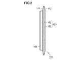
- FIG. 2 is a left side view of the gear wheel diamond rotary dresser viewed from the direction indicated by the arrow II in FIG. 3 is a cross-sectional view taken along line III-III in FIG.
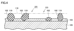
- FIG. 4 is a cross-sectional view showing the structure of the abrasive layer.
- the present invention has been made to solve the above-described problems, and an object thereof is to provide an abrasive tool such as a diamond rotary dresser that has a long life and exhibits a good sharpness.
- an abrasive tool such as a diamond rotary dresser that has a long life and exhibits a good sharpness.
- An abrasive tool is an abrasive tool having an abrasive layer in which a plurality of hard abrasive grains are bonded together by a binder, and each of the plurality of hard abrasive grains has a working surface in contact with a workpiece.
- the ratio of the total area of the plurality of working surfaces to the area of the virtual surface that smoothly connects the plurality of working surfaces is 5% or more and 30% or less.
- the area of the working surface of each hard abrasive grain existing per unit area of the virtual surface of the abrasive layer surface (the total area of the working surfaces of the hard abrasive grains / the area of the virtual surface) is calculated using a microscope. Irradiating light from the normal direction of the abrasive layer surface, removing scattered light from other than the working surface, analyzing and extracting only the reflected image from the working surface of the abrasive layer surface, and calculating the area ratio By the way.
- the area ratio is measured by observing in a field of view of 2 mm ⁇ 2 mm at any three locations on the virtual surface and measuring the area of the working surface by the above method.
- the total value of the surface is the area ratio.
- the abrasive grain area acting during processing is optimally controlled, so that there is little variation in sharpness and the life can be stably extended. If said ratio is less than 5%, since the area of the action surface which acts on a process is too small, the lifetime of an abrasive tool will become short. When said ratio exceeds 30%, the area of an action surface is too large and sharpness deteriorates.
- the ratio (maximum diameter / minimum diameter) of the particle diameters of the abrasive grains having the maximum diameter and the minimum diameter of the plurality of hard abrasive grains used in the abrasive tool is 1.2 or more and 10 or less. is there. If the said ratio is 1.2 or more, since the particle size of a hard abrasive grain can be kept large, favorable sharpness can be maintained. If the said ratio is 10 or less, the dispersion
- the method of measuring the particle size there is a method of removing hard abrasive grains from an abrasive tool and specifying image data of the hard abrasive grains.
- the equivalent circle diameter of the hard abrasive grains is used as the particle diameter.
- the maximum diameter and the minimum diameter of the hard abrasive grains are measured as follows.
- the equivalent circle diameter is the diameter of the hard abrasive grain measured and analyzed by the dry particle image analyzer based on the hard abrasive grain image, and represents the area of the image of each abrasive grain in a deformed shape that is not a circle.
- the diameter of the circle is the equivalent circle diameter, which is the particle diameter.
- the maximum diameter DMAX and the minimum diameter DMIN in the measured particle diameter data are calculated, and DMAX / DMIN is set as the maximum diameter / minimum diameter.
- the hard abrasive grains existing in the abrasive layer are not uniformly made to have a uniform particle size, but the wear speed and state of the individual hard abrasive grains can be varied by providing variation within a certain range. Therefore, the sharpness can be stabilized for a long time when viewed in the whole abrasive layer.
- the plurality of hard abrasive grains are distributed at a density of 50 to 1500 particles / cm 2 in the abrasive grain layer.
- the distribution density is measured as follows. The surface of the abrasive layer is observed with a microscope. The size of the visual field to be observed is set so that 20 to 50 hard abrasive grains can be seen in the visual field, and the number of hard abrasive grains is counted at any three locations. Then, the density of the hard abrasive grain distribution is calculated based on the size of the visual field and the number of hard abrasive grains.
- the Vickers hardness Hv of the plurality of hard abrasive grains is 1000 or more and 16000 or less.
- Typical examples of such hard abrasive grains having Vickers hardness include diamond, cubic boron nitride (cBN), SiC, and Al 2 O 3 .
- the hard abrasive grains may be either single crystal or polycrystal.
- the particle size of the plurality of hard abrasive grains is 91 or more and 1001 or less in the particle size defined in “1: Narrow range” of “Table 1 Types and indications of particle size” of JIS B 4130 (1998). Specifically, those shown in Table 1 below.
- This particle size measurement method is similar to the measurement method of the maximum and minimum diameters of hard abrasive grains. First, cut the abrasive tool in half, dissolve the abrasive layer of one of the abrasive tools, and remove the hard abrasive grains. Take out. And this taken-out abrasive grain is measured based on prescription
- the abrasive layer is a single layer.
- the binding material is nickel plating.
- the abrasive tool is a rotary dresser.
- the rotary dresser is a disk dresser.
- it is used for truing and / or dressing of gear processing wheels.
- the abrasive tool shown below is an abrasive tool that can realize a stable sharpness and long life by controlling the abrasive grains contacting the workpiece to an optimum state. That is, it is an abrasive tool in which the area of abrasive grains acting during processing, the grain size of abrasive grains, the particle size distribution, and the distribution density of abrasive grains are controlled to an optimum state.
- FIG. 1 is a front view of a diamond rotary dresser for gears as an abrasive tool according to an embodiment of the present invention.
- a gear diamond rotary dresser 101 according to an embodiment has a disk-shaped base metal 105, and a diamond layer extends in the circumferential direction on the outer periphery of the base metal 105.
- the abrasive grain layer 123 is composed of a binder 103 constituted by a nickel plating layer and hard abrasive grains 102 constituted by diamond exposed from the binder 103.
- a surface 112 acting on the workpiece appears, and another surface not shown in FIG.
- the width of the abrasive grain layer 123 in the radial direction is constant, but it is not always necessary to make the width constant.
- FIG. 2 is a left side view of the diamond rotary dresser for gears as viewed from the direction indicated by arrow II in FIG.
- the upper end portion and the lower end portion of the abrasive grain layer 123 are “V” -shaped, and the two surfaces 111 and 112 are tapered so as to form a predetermined angle.
- FIG. 3 is a cross-sectional view taken along line III-III in FIG.
- the tapered surfaces 111 and 112 are constituted by an abrasive layer 123 constituted by hard abrasive grains 102 and a binder 103.
- the abrasive layer 123 is fixed to the base metal 105.
- FIG. 4 is a cross-sectional view showing the structure of the abrasive layer.
- a diamond rotary dresser 101 for gears as an abrasive tool has an abrasive layer 123.
- the abrasive grain layer 123 is formed on the base metal 105.
- the abrasive grain layer 123 includes a plurality of hard abrasive grains 102 and a binder 103 for holding diamond abrasive grains.
- the binding material 103 is configured by single-layer nickel plating. A plurality of hard abrasive grains 102 are bonded by a bonding material 103.
- Each of the plurality of hard abrasive grains 102 is formed with a working surface 119 that comes into contact with the workpiece.
- the ratio of the total area of the plurality of working surfaces 119 to the area of the virtual surface 110 that smoothly connects the plurality of working surfaces 119 is 5% or more and 30% or less. Since this ratio is 5% or more and 30% or less, it is possible to provide a diamond rotary dresser 101 for a gear having a good sharpness and a long service life.
- the ratio of the maximum diameter to the minimum diameter (maximum diameter / minimum diameter) of the plurality of hard abrasive grains 102 is preferably 1.2 or more and 10 or less.
- the hard abrasive grains 102 are limited to those having the working surface 119.
- the plurality of hard abrasive grains 102 are preferably distributed in the abrasive grain layer 123 at a density of 50 to 1500 particles / cm 2 .
- the hard abrasive grains 102 are limited to those having the working surface 119. If it is this range, at least one of a sharpness and a lifetime will become very favorable among the performances of a superabrasive wheel.
- the Vickers hardness Hv of the plurality of hard abrasive grains 102 is preferably 1000 or more and 16000 or less. By using hard abrasive grains having such hardness, the sharpness and life of the wheel can be improved.
- the particle diameter of the hard abrasive grains 102 is preferably 91 or more and 1001 or less.
- the working surface 119 is obtained by grinding or polishing the surface of the hard abrasive grains 102 (equalizing the height of the hard abrasive grains 102).
- the ratio of the maximum area to the minimum area (maximum area / minimum area) of the plurality of working surfaces 119 is preferably 1.5 or more and 10 or less.
- Example 2 (Description of each sample) Various wheels shown in Table 2-4 were created. The wheel shape and size are the same for all wheels. The shape of the wheel is the shape shown in FIGS. 1 and 2, and the diameter is 110 mm. The structure of the abrasive layer is different for each sample.
- area ratio of working surfaces is the ratio (%) of the total area of the plurality of working surfaces 119 to the area of the virtual surface 110 that gently connects the plurality of working surfaces 119.
- “Abrasive grain size maximum / minimum ratio” in Table 2-4 is the ratio (maximum diameter / minimum diameter) between the maximum diameter and the minimum diameter of a plurality of hard abrasive grains 102 (limited to those having a working surface 119). means.
- “Abrasive grain distribution density” in Table 2-4 means the distribution density (pieces / cm 2 ) of a plurality of hard abrasive grains 102 (limited to those having a working surface 119).
- Table 2-4 shows the area ratio of the working surface, the maximum diameter / minimum ratio of the abrasive grain size, and the value of the abrasive grain distribution density of the various wheels thus prepared.
- the dressing conditions are shown below.
- Target of dressing grinding wheel for gear grinding (Material: A grinding wheel)
- Dressing conditions Grinding wheel speed: 60-80rpm
- the first dressing is roughing, and the subsequent dressing is finishing.
- the dressing results were evaluated according to the following criteria.
- the performance of the wheel of the present invention was evaluated based on the sharpness and life of the wheel of Comparative Example 2. Evaluation criteria were evaluated in three stages of A, B, and C as follows, with the load current value and life of Comparative Example 2 being 1.0.
- A The load current value was less than 0.6, and extremely stable dressing was possible.
- B The load current value was 0.6 or more and less than 0.8, and stable dressing was possible.
- A The dressing accuracy hardly changed and the lifetime was 2 or more.
- B Although the dressing accuracy gradually deteriorated and the workpiece was slightly burned, the life was 1.2 or more and less than 2.
- the present invention can be used in the field of abrasive tools, for example, superabrasive grinding wheels used to grind a workpiece into a total mold, and abrasive tools such as a diamond rotary dresser used for dressing a grindstone. More particularly, the present invention relates to a diamond rotary dresser for gears, which is used for dressing a grinding wheel for gear machining or dressing with truing.
- abrasive tools for example, superabrasive grinding wheels used to grind a workpiece into a total mold
- abrasive tools such as a diamond rotary dresser used for dressing a grindstone. More particularly, the present invention relates to a diamond rotary dresser for gears, which is used for dressing a grinding wheel for gear machining or dressing with truing.
Landscapes
- Engineering & Computer Science (AREA)
- Mechanical Engineering (AREA)
- Chemical & Material Sciences (AREA)
- Ceramic Engineering (AREA)
- Inorganic Chemistry (AREA)
- Polishing Bodies And Polishing Tools (AREA)
- Grinding-Machine Dressing And Accessory Apparatuses (AREA)
Priority Applications (7)
| Application Number | Priority Date | Filing Date | Title |
|---|---|---|---|
| EP16891647.6A EP3409422B1 (de) | 2016-02-22 | 2016-12-07 | Schleifwerkzeug |
| MX2018009428A MX2018009428A (es) | 2016-02-22 | 2016-12-07 | Herramienta abrasiva. |
| KR1020187026768A KR102221333B1 (ko) | 2016-02-22 | 2016-12-07 | 지립 공구 |
| PL16891647.6T PL3409422T3 (pl) | 2016-02-22 | 2016-12-07 | Narzędzie ścierne |
| CN201680082285.5A CN108698202B (zh) | 2016-02-22 | 2016-12-07 | 磨料工具 |
| US16/078,462 US11819979B2 (en) | 2016-02-22 | 2016-12-07 | Abrasive tool |
| JP2017513557A JP6165388B1 (ja) | 2016-02-22 | 2016-12-07 | 砥粒工具 |
Applications Claiming Priority (2)
| Application Number | Priority Date | Filing Date | Title |
|---|---|---|---|
| JP2016031032 | 2016-02-22 | ||
| JP2016-031032 | 2016-02-22 |
Publications (1)
| Publication Number | Publication Date |
|---|---|
| WO2017145491A1 true WO2017145491A1 (ja) | 2017-08-31 |
Family
ID=59686275
Family Applications (1)
| Application Number | Title | Priority Date | Filing Date |
|---|---|---|---|
| PCT/JP2016/086372 Ceased WO2017145491A1 (ja) | 2016-02-22 | 2016-12-07 | 砥粒工具 |
Country Status (8)
| Country | Link |
|---|---|
| US (1) | US11819979B2 (de) |
| EP (1) | EP3409422B1 (de) |
| JP (1) | JP6165388B1 (de) |
| KR (1) | KR102221333B1 (de) |
| CN (1) | CN108698202B (de) |
| MX (1) | MX2018009428A (de) |
| PL (1) | PL3409422T3 (de) |
| WO (1) | WO2017145491A1 (de) |
Cited By (1)
| Publication number | Priority date | Publication date | Assignee | Title |
|---|---|---|---|---|
| WO2023190008A1 (ja) * | 2022-03-28 | 2023-10-05 | 株式会社アライドマテリアル | ロータリードレッサおよびその製造方法 |
Families Citing this family (2)
| Publication number | Priority date | Publication date | Assignee | Title |
|---|---|---|---|---|
| EP3666462A1 (de) | 2016-04-11 | 2020-06-17 | 3M Innovative Properties Company | Ein grünkörper, eine schleifscheibe und ein verfahren zur herstellung mindestens eines grünkörpers |
| DE102023135290A1 (de) * | 2023-12-15 | 2025-06-18 | KOEPFER Holding GmbH | Schleifkörper mit Aufnahmeräumen für Fließspäne sowie Schleifverfahren |
Citations (5)
| Publication number | Priority date | Publication date | Assignee | Title |
|---|---|---|---|---|
| JP2002292570A (ja) * | 2001-03-29 | 2002-10-08 | Noritake Super Abrasive:Kk | 電着工具 |
| JP2004130475A (ja) * | 2002-10-11 | 2004-04-30 | Noritake Super Abrasive:Kk | Cmpパッドコンディショナー |
| JP2005161449A (ja) * | 2003-12-02 | 2005-06-23 | Allied Material Corp | 鏡面加工用カップ型超砥粒ホイール |
| JP2005279842A (ja) * | 2004-03-29 | 2005-10-13 | Noritake Super Abrasive:Kk | 電着リーマおよびその製造方法 |
| WO2007000831A1 (ja) * | 2005-06-27 | 2007-01-04 | A.L.M.T. Corp. | 歯車用ダイヤモンドロータリードレッサならびにそれを用いた歯車加工用砥石のツルーイングおよびドレッシング方法 |
Family Cites Families (32)
| Publication number | Priority date | Publication date | Assignee | Title |
|---|---|---|---|---|
| JP2679178B2 (ja) | 1988-11-22 | 1997-11-19 | 三菱マテリアル株式会社 | 電着砥石 |
| JPH05269666A (ja) | 1992-03-25 | 1993-10-19 | Toyoda Mach Works Ltd | 砥石の修正方法 |
| JPH06114739A (ja) | 1992-10-09 | 1994-04-26 | Mitsubishi Materials Corp | 電着砥石 |
| US5453312A (en) * | 1993-10-29 | 1995-09-26 | Minnesota Mining And Manufacturing Company | Abrasive article, a process for its manufacture, and a method of using it to reduce a workpiece surface |
| JPH07237128A (ja) | 1994-02-28 | 1995-09-12 | Nachi Fujikoshi Corp | 電着工具 |
| DE19624842C2 (de) | 1996-06-21 | 2000-08-10 | Reishauer Ag | Verfahren zum flexiblen Profilieren von Schleifschnecken, ein Profilierwerkzeug und eine Vorrichtung zur Durchführung des Verfahrens |
| US6368198B1 (en) * | 1999-11-22 | 2002-04-09 | Kinik Company | Diamond grid CMP pad dresser |
| JP3052896B2 (ja) | 1997-06-13 | 2000-06-19 | 日本電気株式会社 | 研磨布表面のドレス治具及びその製造方法 |
| DE19907363A1 (de) | 1999-02-20 | 2000-08-24 | Reishauer Ag | Topologisches Profilieren von Schleifschnecken für das kontinuierliche Wälzschleifen von Verzahnungen |
| US6319108B1 (en) * | 1999-07-09 | 2001-11-20 | 3M Innovative Properties Company | Metal bond abrasive article comprising porous ceramic abrasive composites and method of using same to abrade a workpiece |
| US6419574B1 (en) | 1999-09-01 | 2002-07-16 | Mitsubishi Materials Corporation | Abrasive tool with metal binder phase |
| US6544373B2 (en) | 2001-07-26 | 2003-04-08 | United Microelectronics Corp. | Polishing pad for a chemical mechanical polishing process |
| JP2003089064A (ja) | 2001-09-14 | 2003-03-25 | Asahi Diamond Industrial Co Ltd | ロータリツルーア及びその製造方法 |
| JP2003200352A (ja) | 2001-12-27 | 2003-07-15 | Noritake Super Abrasive:Kk | 電着工具 |
| JP2003260663A (ja) | 2002-03-07 | 2003-09-16 | Ebara Corp | ポリッシング装置及びポリッシング方法 |
| JP4215570B2 (ja) | 2003-06-09 | 2009-01-28 | 株式会社ノリタケスーパーアブレーシブ | ドレッサ |
| US20080041354A1 (en) | 2004-08-16 | 2008-02-21 | Toyoda Van Mopppes Ltd. | Rotary Diamond Dresser |
| KR101293461B1 (ko) | 2005-08-25 | 2013-08-07 | 이시즈카히로시 | 소결체 연마부가 구비된 공구 및 그 제조 방법 |
| JP5506141B2 (ja) * | 2006-04-18 | 2014-05-28 | 新日鐵住金株式会社 | 耐候性鋼のさび除去および素地調整に優れた回転研削工具およびその製造方法ならびにそれを用いた耐候性鋼の素地調整方法 |
| WO2007119886A1 (ja) | 2006-04-18 | 2007-10-25 | Nippon Steel Materials Co., Ltd. | さび除去および素地調整に優れた回転研削工具およびその製造方法ならびにそれを用いたさび除去および素地調整方法 |
| US20080271384A1 (en) * | 2006-09-22 | 2008-11-06 | Saint-Gobain Ceramics & Plastics, Inc. | Conditioning tools and techniques for chemical mechanical planarization |
| JP4354482B2 (ja) | 2006-12-26 | 2009-10-28 | 株式会社ノリタケスーパーアブレーシブ | ツルーイング工具 |
| US7517277B2 (en) | 2007-08-16 | 2009-04-14 | Rohm And Haas Electronic Materials Cmp Holdings, Inc. | Layered-filament lattice for chemical mechanical polishing |
| KR101251893B1 (ko) | 2007-08-23 | 2013-04-08 | 생-고벵 아브라시프 | 차세대 산화막/금속막 cmp를 위한 최적 cmp 컨디셔너 설계 |
| CN101508087B (zh) | 2009-03-25 | 2011-01-05 | 浙江工业大学 | 金刚石薄膜研磨方法及其触媒砂轮 |
| CA2773197A1 (en) * | 2012-03-27 | 2013-09-27 | Yundong Li | Electroplated super abrasive tools with the abrasive particles chemically bonded and deliberately placed, and methods for making the same |
| JP2014083673A (ja) * | 2012-10-26 | 2014-05-12 | Riken Corundum Co Ltd | 砥粒付ワイヤ工具 |
| JP2014205225A (ja) | 2013-04-15 | 2014-10-30 | 株式会社ノリタケカンパニーリミテド | 高硬度脆性材料の研削用砥石 |
| ES2756849T3 (es) | 2013-08-07 | 2020-04-27 | Reishauer Ag | Herramienta rectificadora y procedimiento para su fabricación |
| CN103846817B (zh) | 2014-01-29 | 2017-01-11 | 南京航空航天大学 | 磨料群与气孔三维可控排布cbn砂轮制造方法 |
| AU2015247741A1 (en) * | 2014-04-14 | 2016-11-10 | Saint-Gobain Ceramics & Plastics, Inc. | Abrasive article including shaped abrasive particles |
| CN107405755B (zh) * | 2015-12-10 | 2019-03-22 | 联合材料公司 | 超硬磨料砂轮 |
-
2016
- 2016-12-07 MX MX2018009428A patent/MX2018009428A/es unknown
- 2016-12-07 CN CN201680082285.5A patent/CN108698202B/zh active Active
- 2016-12-07 PL PL16891647.6T patent/PL3409422T3/pl unknown
- 2016-12-07 US US16/078,462 patent/US11819979B2/en active Active
- 2016-12-07 KR KR1020187026768A patent/KR102221333B1/ko active Active
- 2016-12-07 WO PCT/JP2016/086372 patent/WO2017145491A1/ja not_active Ceased
- 2016-12-07 JP JP2017513557A patent/JP6165388B1/ja active Active
- 2016-12-07 EP EP16891647.6A patent/EP3409422B1/de active Active
Patent Citations (5)
| Publication number | Priority date | Publication date | Assignee | Title |
|---|---|---|---|---|
| JP2002292570A (ja) * | 2001-03-29 | 2002-10-08 | Noritake Super Abrasive:Kk | 電着工具 |
| JP2004130475A (ja) * | 2002-10-11 | 2004-04-30 | Noritake Super Abrasive:Kk | Cmpパッドコンディショナー |
| JP2005161449A (ja) * | 2003-12-02 | 2005-06-23 | Allied Material Corp | 鏡面加工用カップ型超砥粒ホイール |
| JP2005279842A (ja) * | 2004-03-29 | 2005-10-13 | Noritake Super Abrasive:Kk | 電着リーマおよびその製造方法 |
| WO2007000831A1 (ja) * | 2005-06-27 | 2007-01-04 | A.L.M.T. Corp. | 歯車用ダイヤモンドロータリードレッサならびにそれを用いた歯車加工用砥石のツルーイングおよびドレッシング方法 |
Non-Patent Citations (1)
| Title |
|---|
| See also references of EP3409422A4 * |
Cited By (2)
| Publication number | Priority date | Publication date | Assignee | Title |
|---|---|---|---|---|
| WO2023190008A1 (ja) * | 2022-03-28 | 2023-10-05 | 株式会社アライドマテリアル | ロータリードレッサおよびその製造方法 |
| JP7441381B1 (ja) * | 2022-03-28 | 2024-02-29 | 株式会社アライドマテリアル | ロータリードレッサおよびその製造方法 |
Also Published As
| Publication number | Publication date |
|---|---|
| CN108698202B (zh) | 2021-06-04 |
| KR20180112032A (ko) | 2018-10-11 |
| EP3409422A4 (de) | 2019-08-14 |
| EP3409422A1 (de) | 2018-12-05 |
| CN108698202A (zh) | 2018-10-23 |
| US20190054592A1 (en) | 2019-02-21 |
| KR102221333B1 (ko) | 2021-03-02 |
| JPWO2017145491A1 (ja) | 2018-03-01 |
| PL3409422T3 (pl) | 2024-07-15 |
| JP6165388B1 (ja) | 2017-07-19 |
| US11819979B2 (en) | 2023-11-21 |
| MX2018009428A (es) | 2018-11-09 |
| EP3409422B1 (de) | 2024-05-22 |
Similar Documents
| Publication | Publication Date | Title |
|---|---|---|
| US9701043B2 (en) | Dicing blade | |
| JP4742845B2 (ja) | 半導体ウエーハの面取り部の加工方法及び砥石の溝形状の修正方法 | |
| JPH11267902A (ja) | 超微細切刃付き工具及び超微細切刃付き加工具 | |
| JP6165388B1 (ja) | 砥粒工具 | |
| CN113329846B (zh) | 高硬质脆性材料用金属结合剂磨石 | |
| JP6270796B2 (ja) | 固定砥粒ワイヤーソー及び固定砥粒ワイヤーのドレッシング方法 | |
| JP2008200780A (ja) | 混合砥粒砥石 | |
| JP2014205225A (ja) | 高硬度脆性材料の研削用砥石 | |
| JP2011251380A (ja) | 平面ホーニング加工用超砥粒ホイール | |
| JP4852892B2 (ja) | ツルーイング工具および研削砥石のツルーイング方法 | |
| KR20160000406A (ko) | 스크라이빙 휠 및 그의 제조 방법 | |
| JPH08243928A (ja) | セグメント型砥石車及びその製造方法 | |
| EP2790877B1 (de) | Verfahren zum abrichten einer schleifscheibe mit einem polykristallinen synthetischen cvd-diamant-abrichter und herstellungsverfahren dafür | |
| WO2017098764A9 (ja) | 超砥粒ホイール | |
| JP4354482B2 (ja) | ツルーイング工具 | |
| JP2005001020A (ja) | ドレッサ | |
| JP3690994B2 (ja) | 電着工具の製造方法 | |
| JP2021146464A (ja) | トリミング用ブレードおよびウェーハの製造方法 | |
| JP2021146465A (ja) | トリミング用ブレードのドレッシングプレート、およびトリミング用ブレードのドレッシング方法 | |
| JP5253254B2 (ja) | ドレッサ | |
| JP2026056275A (ja) | 加工工具 | |
| JPH11138446A (ja) | 多刃研削工具の製造方法 | |
| JP2002187071A (ja) | 電鋳薄刃砥石 | |
| JP2884030B2 (ja) | 内周形切断砥石及びその製造方法 | |
| JP5721877B2 (ja) | 薄刃ブレード |
Legal Events
| Date | Code | Title | Description |
|---|---|---|---|
| ENP | Entry into the national phase |
Ref document number: 2017513557 Country of ref document: JP Kind code of ref document: A |
|
| WWE | Wipo information: entry into national phase |
Ref document number: MX/A/2018/009428 Country of ref document: MX |
|
| NENP | Non-entry into the national phase |
Ref country code: DE |
|
| WWE | Wipo information: entry into national phase |
Ref document number: 2016891647 Country of ref document: EP |
|
| ENP | Entry into the national phase |
Ref document number: 2016891647 Country of ref document: EP Effective date: 20180830 |
|
| ENP | Entry into the national phase |
Ref document number: 20187026768 Country of ref document: KR Kind code of ref document: A |
|
| WWE | Wipo information: entry into national phase |
Ref document number: 1020187026768 Country of ref document: KR |
|
| 121 | Ep: the epo has been informed by wipo that ep was designated in this application |
Ref document number: 16891647 Country of ref document: EP Kind code of ref document: A1 |