WO2017145689A1 - Électrodes d'électroporation - Google Patents
Électrodes d'électroporation Download PDFInfo
- Publication number
- WO2017145689A1 WO2017145689A1 PCT/JP2017/003733 JP2017003733W WO2017145689A1 WO 2017145689 A1 WO2017145689 A1 WO 2017145689A1 JP 2017003733 W JP2017003733 W JP 2017003733W WO 2017145689 A1 WO2017145689 A1 WO 2017145689A1
- Authority
- WO
- WIPO (PCT)
- Prior art keywords
- electrode
- needle
- syringe
- polarity
- electroporation
- Prior art date
- Legal status (The legal status is an assumption and is not a legal conclusion. Google has not performed a legal analysis and makes no representation as to the accuracy of the status listed.)
- Ceased
Links
Images




Classifications
-
- A—HUMAN NECESSITIES
- A61—MEDICAL OR VETERINARY SCIENCE; HYGIENE
- A61N—ELECTROTHERAPY; MAGNETOTHERAPY; RADIATION THERAPY; ULTRASOUND THERAPY
- A61N1/00—Electrotherapy; Circuits therefor
- A61N1/02—Details
- A61N1/04—Electrodes
- A61N1/0404—Electrodes for external use
- A61N1/0408—Use-related aspects
- A61N1/0412—Specially adapted for transcutaneous electroporation, e.g. including drug reservoirs
-
- A—HUMAN NECESSITIES
- A61—MEDICAL OR VETERINARY SCIENCE; HYGIENE
- A61B—DIAGNOSIS; SURGERY; IDENTIFICATION
- A61B18/00—Surgical instruments, devices or methods for transferring non-mechanical forms of energy to or from the body
- A61B18/04—Surgical instruments, devices or methods for transferring non-mechanical forms of energy to or from the body by heating
- A61B18/12—Surgical instruments, devices or methods for transferring non-mechanical forms of energy to or from the body by heating by passing a current through the tissue to be heated, e.g. high-frequency current
- A61B18/14—Probes or electrodes therefor
- A61B18/1402—Probes for open surgery
-
- A—HUMAN NECESSITIES
- A61—MEDICAL OR VETERINARY SCIENCE; HYGIENE
- A61N—ELECTROTHERAPY; MAGNETOTHERAPY; RADIATION THERAPY; ULTRASOUND THERAPY
- A61N1/00—Electrotherapy; Circuits therefor
- A61N1/18—Applying electric currents by contact electrodes
- A61N1/32—Applying electric currents by contact electrodes alternating or intermittent currents
- A61N1/327—Applying electric currents by contact electrodes alternating or intermittent currents for enhancing the absorption properties of tissue, e.g. by electroporation
-
- A—HUMAN NECESSITIES
- A61—MEDICAL OR VETERINARY SCIENCE; HYGIENE
- A61B—DIAGNOSIS; SURGERY; IDENTIFICATION
- A61B18/00—Surgical instruments, devices or methods for transferring non-mechanical forms of energy to or from the body
- A61B2018/00315—Surgical instruments, devices or methods for transferring non-mechanical forms of energy to or from the body for treatment of particular body parts
- A61B2018/00452—Skin
-
- A—HUMAN NECESSITIES
- A61—MEDICAL OR VETERINARY SCIENCE; HYGIENE
- A61B—DIAGNOSIS; SURGERY; IDENTIFICATION
- A61B18/00—Surgical instruments, devices or methods for transferring non-mechanical forms of energy to or from the body
- A61B2018/00571—Surgical instruments, devices or methods for transferring non-mechanical forms of energy to or from the body for achieving a particular surgical effect
- A61B2018/00613—Irreversible electroporation
-
- A—HUMAN NECESSITIES
- A61—MEDICAL OR VETERINARY SCIENCE; HYGIENE
- A61B—DIAGNOSIS; SURGERY; IDENTIFICATION
- A61B18/00—Surgical instruments, devices or methods for transferring non-mechanical forms of energy to or from the body
- A61B18/04—Surgical instruments, devices or methods for transferring non-mechanical forms of energy to or from the body by heating
- A61B18/12—Surgical instruments, devices or methods for transferring non-mechanical forms of energy to or from the body by heating by passing a current through the tissue to be heated, e.g. high-frequency current
- A61B18/14—Probes or electrodes therefor
- A61B2018/1405—Electrodes having a specific shape
- A61B2018/1425—Needle
- A61B2018/143—Needle multiple needles
-
- A—HUMAN NECESSITIES
- A61—MEDICAL OR VETERINARY SCIENCE; HYGIENE
- A61N—ELECTROTHERAPY; MAGNETOTHERAPY; RADIATION THERAPY; ULTRASOUND THERAPY
- A61N1/00—Electrotherapy; Circuits therefor
- A61N1/02—Details
- A61N1/04—Electrodes
- A61N1/0404—Electrodes for external use
- A61N1/0408—Use-related aspects
- A61N1/0412—Specially adapted for transcutaneous electroporation, e.g. including drug reservoirs
- A61N1/0416—Anode and cathode
- A61N1/0424—Shape of the electrode
Definitions
- the present invention relates to an electrode for electroporation including a plurality of first polarity electrode needles, wherein the attached syringe needle can be used as a second polarity electrode needle.
- the electroporation method is a method for realizing a simple and efficient introduction of foreign substances into cells by opening micropores in the cell membrane of target cells by electrical stimulation. Since it is a highly versatile and simple method for introducing nucleic acids, drug components, and the like into cells, demand is increasing especially in research and development in the field of life sciences and in medical practice. However, with the spread of the electroporation method, further problems are recognized in specific fields. For example, in vivo electroporation is an important technique in the field of research into muscle tissue, skin tissue, etc., and it has been pointed out that the introduction efficiency of foreign substances is low, and improvement of its efficiency is required. ing.
- the main reason for the low efficiency of electroporation for introduction into muscular tissue, skin tissue, etc. by the in vivo method is that the experimenter or engineer needs to learn advanced handling techniques.
- an operation procedure for performing in vivo electroporation on muscle tissue, skin tissue or the like using a general needle-type electrode i) injection of a solution containing the introduced substance into the target tissue, and ii) injection Mark the area with a magic, etc., iii) remove the injection needle, iv) adjust the depth of needle insertion using the needle-type electrode, and v) accurately perform a series of operations such as applying an electrical pulse to the target tissue
- there is a method of performing it quickly is i) injection of a solution containing the introduced substance into the target tissue, and ii) injection Mark the area with a magic, etc., iii) remove the injection needle, iv) adjust the depth of needle insertion using the needle-type electrode, and v) accurately perform a series of operations such as applying an electrical pulse to the
- an electrode device for electroporation treatment for handheld including an electrode array including a plurality of electrode needles is disclosed (Patent Document 1). . Since the electrode device for handheld treatment according to Patent Document 1 is provided with a plurality of electrode needles, an increase in the electric field generation region can be expected. On the other hand, after injecting the introduction substance, the injection needle is pulled out and the electrode needle is removed. Since the above-described series of operations such as pricking and depth adjustment is essential, it is not possible to expect an essential improvement in the operability of the in vivo method. Therefore, when the electrode device described in Patent Document 1 is used, a great improvement cannot be expected in the stable improvement of the introduction efficiency by the in vivo method.
- Patent Document 2 a therapeutic electrode device in which one or more electrodes of an electrode array including a plurality of electrode needles are cannulated is disclosed (Patent Document 2).
- the part which comprises the electrode array in patent document 2 is a part of part of the electric device for handheld treatment, and a cannulated needle is only a part of an integrated structure with other electrode needles.
- the electrode device described in Patent Document 2 is a device in which a multi-electrode needle and an electrode system, a cannula needle and a liquid supply pipe system, a control system, and the like are completely integrated.
- the needle and the liquid supply pipe attached to the needle need to be replaced, and there are problems in the speed and simplicity of device assembly and sample filling in the pre-experiment preparation.
- a member dedicated to the apparatus of the liquid supply system such as a pipe member is reused, there are concerns about problems such as contamination and infection. Therefore, when the electrode array of the device described in Patent Document 2 is used, the device cannot be recognized as a device having a structure that can be used stably and simply at a research site or a treatment site.
- the device described in Patent Document 2 is a device that has a new technical problem that has not been found in other prior arts.
- the present invention has been made in view of the circumstances of the above-described prior art, and the subject of the present invention is a technique capable of stably improving the foreign substance introduction efficiency, without depending on the skill level of the operator.
- An object is to provide a technique that enables electroporation by an in vivo method by a quick and simple operation.
- the present inventors have intensively studied, and as a result, have conceived the technology using the structure including the first polarity electrode needle, the electrode needle holding portion, and the syringe holding portion as a member electrode.
- the electrode needle holding part is a structure including an outer frame support lower structure and a first polarity energization part, and the first polarity electrode needle is formed from the bottom surface of the outer frame support lower structure.
- the electrode for electroporation includes a syringe holding portion on which a syringe needle can be inserted by inserting a syringe needle on the opposite side of the electrode needle holding portion from the electroporation object side, and the syringe It was conceived of a member configuration that is a structure having a syringe needle insertion / extraction path provided with at least a part of the second polarity energization part, in which the holding part is made of a conductive material.
- the present inventors use the attached syringe needle as the second polarity electrode needle by attaching the existing syringe provided with the syringe needle to the syringe holding portion of the electrode structure having the plurality of first polarity electrode needles.
- the present inventors have conceived the idea of a member electrode having a structure that allows an existing disposable syringe to be attached and detached, and produced an electrode structure. And the effect was demonstrated by gene introduction experiment.
- the present inventors can stabilize a series of operations up to injection of a solution containing a foreign substance and voltage application in a very short time without depending on the skill level of the operator. And found that it was feasible.
- the present inventors have found that the introduction efficiency of electroporation by an in vivo method can be improved.
- the sample filling operation can be performed only by mounting the syringe, it is possible to perform the operation quickly and easily including preparation operations such as assembly of the electrode device and sample injection.
- sample exchange can be easily performed by syringe exchange, contamination and the risk of infection were reduced.
- Patent Documents 1 and 2 in the above-described prior art only disclose an integrated structure as an electrode device for handheld treatment, and the syringe needle is made detachable from an existing syringe and the second polarity electrode is used. There are no disclosures or suggestions regarding the idea of use as a needle and the specific means enabling it to be realized.
- An electroporation electrode having a plurality of electrode needles (A) having a structure including a first polarity electrode needle, an electrode needle holding portion, and a syringe holding portion; (B) The electrode needle holding portion is a structure including an outer frame support lower structure and a first polarity energization portion, and a syringe holding portion side on the bottom surface of the outer frame support lower structure; It has a syringe needle insertion hole that communicates, (C) It has a structure in which two or more first polar electrode needles protrude from the bottom surface of the outer frame support lower structure toward the electroporation object side, (D) (d-1) The electrode for electroporation includes a syringe holding portion on the side opposite to the electroporation object side of the electrode needle holding portion so that a syringe needle can be inserted and attached to the syringe.
- the syringe holding part is a structure having a syringe needle insertion / extraction path provided at least in part with a second polarity energization part made of a conductive material.
- An electrode for electroporation characterized by the above.
- the electroporation electrode is mounted on the syringe holding part, the syringe needle protruding from the syringe needle insertion / extraction hole through contact with the second polarity energization part is used as the second polarity electrode needle.
- the electrode for electroporation according to Item 1 which is a member electrode that enables the electrode.
- the first polarity electrode needle is Syringe needle insertion / extraction on a straight line or a substantially straight line connecting the tips of the first polarity electrode needles or a polygon formed with the tips of the first polarity electrode needles as apexes in the bottom view of the outer frame support lower structure It is arranged so that the hole is located, Item 3.
- the electrode for electroporation according to any one of Items 1 and 2.
- At least a part of the second polarity energization part in the syringe needle insertion / extraction path has a structure having a straight tube structure made of a conductive substance, and an inner diameter or an inner width that ensures contact with the syringe needle when the syringe needle is inserted.
- Item 4 The electrode for electroporation according to any one of Items 1 to 3, which comprises: [Section 5] Item 5.
- the electroporation according to any one of Items 1 to 4, wherein the first polarity electrode needle has a structure that passes through an outer frame support lower structure of the electrode needle holding portion and is connected to the first polarity energization portion. Electrode.
- the electrode for electroporation is (E) (e-1)
- the first polarity electrode needle has a structure that can be attached and detached at the connection portion with the first polarity energization portion, or (e-2) the first polarity energization portion is By having a structure with a separable connection part, it is possible to attach and detach the first polar electrode needle together with a part or all of the outer frame support lower structure.
- Item 6 The electrode for electroporation according to any one of Items 1 to 5.
- Item 8 The electroporation electrode according to any one of Items 1 to 7, wherein the number of the first polar electrode needles is 3 or more.
- the first polarity electrode needle is disposed in a range of 0.5 to 10 mm from the center of the syringe needle insertion / extraction hole in a bottom view of the outer frame support lower structure.
- the first polar electrode needles are arranged on a concentric circle or a substantially concentric circle centered on the syringe needle insertion / exit hole at a bottom view of the outer frame support lower structure at regular intervals or substantially regular intervals.
- Item 10 The electrode for electroporation according to any one of Items 1 to 9.
- Item 11 The electro of any one of Items 1 to 10, wherein the first polarity electrode needle is a fixed electrode needle having an electrode length of 1 to 10 mm protruding from the bottom surface of the outer frame support lower structure in the electrode needle holding portion. Electrode for poration.
- Electrode for poration [Claim 12] Item 12.
- the electrode for electroporation, wherein the protruding syringe needle via the pin functions as a second polarity electrode needle.
- the present invention is a technique capable of stably improving the efficiency of introducing foreign substances, and enables electroporation by an in vivo method by a quick and simple operation without depending on the skill level of the operator.
- Technology can be provided.
- it is possible to perform suitable electroporation by an in vivo method on muscle tissue, skin tissue, or the like that tends to have low introduction efficiency in the conventional method.
- FIG. 1A Perspective view from above.
- FIG. 1B is a perspective view from the bottom surface direction.
- FIG. 2A Perspective view from above.
- FIG. 2B is a perspective view from the bottom direction.
- FIG. 12A is a photographic image diagram from the bottom view on the outer frame support lower structure side.
- FIG. 12B is a photographic image from the top view, which is the syringe head mounting part side.
- FIG. 13A Photographic image from a side view.
- FIG. 13B A photographic image from a side view with the syringe mounted.
- FIG. 14A DNA injection amount 0 ⁇ g.
- FIG. 14B DNA injection volume 25 ⁇ g.
- FIG. 14C DNA injection volume 50 ⁇ g.
- FIG. 14D DNA injection volume 75 ⁇ g.
- FIG. 14E DNA injection volume 100 ⁇ g.
- the “electroporation method” is a method in which an electric pulse is applied to a cell, and a small hole through which the foreign substance can pass is temporarily formed in the cell membrane to incorporate the foreign substance into the cell. It is.
- This is a versatile foreign substance introduction method that can be applied to various biological species and various types of tissues and cells.
- in vivo means in vivo. It is a term contrasted with “in vitro” meaning in vitro.
- exogenous introduction substance hereinafter sometimes referred to as a foreign substance, an introduction substance, etc.
- a foreign substance, an introduction substance, etc. means a substance to be introduced into cells from the outside by electroporation.
- any substance that can be introduced by the electroporation method is included.
- various physiologically active substances, drugs, therapeutic agents, nucleic acid substances, peptides, proteins, etc. that cannot or cannot easily permeate the cell membrane under normal conditions are exemplified.
- examples of the nucleic acid substance include DNA and RNA.
- a DNA having a nucleic acid sequence to be introduced into the target cell is appropriately selected.
- a full-length gene sequence cDNA sequence, genomic sequence
- partial sequence e.g., regulatory region, spacer region, and a sequence with mutations added.
- DNA designed according to the purpose is used, it is not particularly limited to these.
- RNA examples include mRNA, siRNA and the like, but are not particularly limited thereto.
- first polarity and “second polarity” refer to the polarity of the other electrode (in this case, the negative polarity) when one electrode polarity (for example, positive polarity) of the applied voltage is the first polarity. ) As the second polarity.
- the first polarity and the second polarity can be arbitrary charges.
- the “syringe” is used as a term indicating the entire syringe (50) in a state where the syringe barrel (53), the plunger (54), and the injection needle (52: syringe needle) are assembled. It is.
- the syringe holding unit side is expressed as the upper side unless otherwise defined.
- the outer frame support lower structure side of the electrode needle holding portion is expressed as the lower side unless otherwise defined. It is.
- expressions relating to directions such as “upper”, “lower”, “upper”, “lower”, “bottom”, “horizontal”, “vertical” The terminology used for the description of the structure is not necessarily limited to such a usage mode in the actual usage mode of the electrode.
- a square or the like refers to a deformed figure having a rounded corner with respect to the target figure and a shape having a slightly distorted outer periphery.
- an array state such as a lattice
- deformation of a figure or the like formed by the array components is allowed.
- straight lines are allowed to contain distortions and curves with low curvature.
- the three-dimensional case can be defined in the same manner in the overall form and the cross-sectional form.
- Electroporation electrode having a plurality of electrode needles The present invention includes a plurality of electrode needles having a structure including a first polarity electrode needle (11), an electrode needle holding part (10), and a syringe holding part (20).
- the present invention relates to an electrode for electroporation. Specifically, it is an electrode for electroporation having a plurality of first polarity electrode needles, and the syringe needle (52) attached when the syringe (50) is in the attached state is used as the second polarity electrode needle.
- the present invention relates to an electrode for electroporation that makes it possible.
- Table which arranged the attribute of the structural member about the main member which comprises the electrode (1) for electroporation which concerns on this invention is shown below.
- Table 1 is a table in which attributes of each constituent member are arranged, and does not represent essential members. In this respect, the technical scope according to the present invention is not limited to an embodiment including all the members shown in Table 1.
- the electrode (1) for electroporation is an electrode comprising a first polarity electrode needle (11), an electrode needle holding portion (10) and the like as a structure relating to the first polarity.
- a structure regarding the first polarity a structure including a support member for increasing the strength of the outer frame support body, such as a wiring for connecting to a power source, a conductive wire, and / or a power cable can be used. .
- the first polar electrode needle (11) is disposed on the electroporation object side from the bottom surface of the outer frame support lower structure (12) constituting the electrode needle holding portion. It is an electrode which has the structure which protruded.
- the “first polarity electrode needle” (11) means a needle-like electrode indicating one electrode polarity of an applied voltage. It is preferable that the first polarity electrode needle is made of a conductive material.
- the material constituting the first polarity electrode needle (11) may be any material that can be used as a normal electrode. For example, materials of stainless steel, platinum, steel, copper, iron, titanium alloy, aluminum alloy, carbon and the like are suitable. In particular, a metallic material that is not easily rusted and does not have a concern about the influence on the living body is preferable as the material constituting the first polarity electrode needle (11). For example, a material such as stainless steel, platinum, titanium alloy or the like is suitable.
- the first polarity electrode needle (11) may have any shape as long as the tip is sharp and has a needle shape or a needle shape suitable for perforating a target biological tissue. If the tip is sharp, a shape having an angle or curvature such as a bent shape or a curved shape is allowed. Further, as the first polarity electrode needle (11), a branched shape, a shape branched into a plurality of needles in the distal direction, a shape in which a plurality of needles merged in the distal direction, and the like can be adopted. Moreover, the structure by which the base side of the electrode needle protruded from the bottom face of the outer frame support lower structure (12) is covered with an insulating member can be adopted.
- the base side protruding from the bottom surface of the outer frame support lower structure (12) has a structure such as a plane, a substantially flat surface, an annular shape, etc. arranged at a horizontal or shallow angle with the bottom surface direction of the outer frame support lower structure. And having a structure in which one or two or more needle-shaped or needle-shaped shapes protrude from the structure portion can be employed.
- the shape of the first polar electrode needle (11) is preferably a shape including a sharp straight bar shape or a straight tubular needle shape. More preferably, a sharp straight bar shape or a straight tubular shape used in medical treatment or acupuncture can be used.
- the needle examples include a scarlet needle shape, a hollow needle shape, an injection needle shape, a heel shape, and an acute angle cone shape.
- the cross section of the needle examples include a circular shape, a substantially circular shape, an oval shape, an elliptical shape, a circular shape, and a rectangular shape, and a circular shape or a substantially circular shape is particularly preferable.
- the outer diameter of the cross section of the first polar electrode needle (11) may be any diameter suitable for perforating a living tissue, for example, 0.5 mm or less, preferably 0.4 mm or less, more preferably 0.
- the lower limit is not particularly limited as long as the needle strength can be ensured, and examples thereof include 0.1 mm or more, preferably 0.15 mm or more.
- the first polarity electrode needle (11) is a fixed electrode needle.
- an electrode provided with a mechanism that allows the length of the first polarity electrode needle to be freely adjusted is also possible.
- the first polar electrode needle is a fixed electrode needle.
- the electrode needle length of the first polarity electrode needle (11) is 1 mm or longer, preferably 2 mm or longer, more preferably 2 mm or longer, with the electrode length protruding from the bottom surface of the outer frame support lower structure (12) of the electrode needle holder. It is suitable that it is 3 mm or more, more preferably 4 mm or more.
- the upper limit is preferably 10 mm or less, preferably 8 mm or less, more preferably 6 mm or less, and still more preferably 5 mm or less. That is, 1 to 10 mm, preferably 2 to 8 mm, more preferably 3 to 6 mm, and still more preferably 4 to 5 mm.
- the difference in electrode length between the first polar electrode needles is compared with the average needle length of the first polar electrode needles protruding from the bottom surface of the outer frame support lower structure (12) of the electrode needle holding portion.
- a range of -2 to +2 mm preferably a range of -1 to +1 mm, more preferably a range of -0.5 to +0.5 mm, and still more preferably a range of -0.2 to +0.2 mm.
- the base portion of the first polarity electrode needle (11) is embedded in the outer frame support lower structure (12) of the electrode needle holding portion and is not considered in the needle length. Therefore, the needle length of the embedded base portion is not particularly limited and can be employed. Further, the electrode needle length of the first polar electrode needle (11) is preferably a length representing the electrode length of a straight rod-like or straight tubular portion of the portion protruding from the bottom surface.
- the electrode (1) for electroporation according to the present invention has a structure including a fixed electrode needle having the above-mentioned predetermined electrode needle length, so that complicated operations such as depth adjustment are performed when the needle is inserted into muscle or skin. Is no longer necessary.
- the fixed electrode needle length within the range of the electrode length can realize an appropriate depth when electroporation is performed on muscles, skin, or the like. Therefore, the electrode for electroporation according to the present invention can be inserted into a depth appropriate for electroporation by a simple operation of pushing the electrode needle to the root.
- the first polarity electrode needle (11) is disposed at the first polarity electrode needle (11) in the bottom view of the outer frame support lower structure (12).
- the syringe needle insertion hole (46) is located on a straight line or a substantially straight line connecting the tips of the needles) or inside a polygon formed with the tip of the first polarity electrode needle (11) as a vertex.
- the bottom of the outer frame support lower structure (12) is a straight line or a substantially straight line connecting the bases of the first polar electrode needles (11) or the base of the first polar electrode needles (11) as a vertex.
- the syringe needle insertion / exit hole (46) is positioned inside the formed polygon. Further, the position where the first polarity electrode needle (11) is arranged is from the center of the syringe needle insertion / extraction hole (46) in the bottom view of the outer frame support lower structure (12) of the electrode needle holding portion. Arranged in the range of 0.5 to 10 mm, preferably in the range of 0.5 to 5 mm, more preferably in the range of 0.75 to 4 mm, still more preferably in the range of 1 to 3 mm, and particularly preferably in the range of 1 to 2 mm. It is suitable.
- the range is preferably a range that represents the distance between the tip of the electrode needle and the syringe needle insertion / extraction hole in a bottom view.
- V / cm electric field strength
- the range is preferably a range that represents the distance between the tip of the electrode needle and the syringe needle insertion / extraction hole in a bottom view.
- the position where the first polarity electrode needle (11) is arranged is a concentric circle centering on the syringe needle insertion hole (46) in the bottom view of the outer frame support lower structure (12) of the electrode needle holder. It is preferable that they are arranged on top or substantially concentric circles. Moreover, as a position where the 1st polarity electrode needle
- the first polar electrode needle (11) is formed as the apex in the bottom view of the outer frame support lower structure (12) of the electrode needle holding portion.
- the polygon to be formed is a position that becomes a regular polygon or a substantially regular polygon. The position preferably represents the position of the tip of the electrode needle and the syringe needle insertion / exit hole in a bottom view.
- each of the first polar electrode needle (11) and the syringe needle (52) (or the syringe needle insertion / exit hole (46)) as the second polar electrode needle.
- each electric field between the first polar electrode needles (11) is closer to the equidistant, so that a uniform electric field can be generated.
- the number of the first polar electrode needles (11) protruding from the bottom surface of the outer frame support lower structure (12) can be two or more. However, it is more preferable that the number is 3 or more.
- the number is 3 or more.
- a suitable number of the first polar electrode needle (11) is 2 to 8, preferably 3 to 7, more preferably 3 to 6, further preferably 3 to 5, particularly preferably 3 to 4. is there.
- the number of the first polar electrode needles (11) in principle, the larger the number, the larger the area of electroporation is preferable.
- the manufacturing efficiency and cost are greater than the effect of increasing the number of electrodes, and there is a risk of giving some pain to the subject and the target sample, which is not suitable. .
- the angle at which the first polarity electrode needle (11) protrudes from the bottom surface of the outer frame support lower structure (12) of the electrode needle holder is perpendicular to the bottom surface of the outer frame support lower structure and / or substantially the same. Those arranged and fixed so as to be vertical are preferable.
- substantially perpendicular refers to an angle in the range of 90 ⁇ 10 °, preferably 90 ⁇ 5 °, more preferably 90 ⁇ 2 ° with respect to the bottom surface of the outer frame support lower structure (12). Is preferred.
- the protrusion angle of the 1st polarity electrode needle (11) is not an angle of an appropriate range, the insertion and extraction of a needle
- it is arranged and fixed so as to be perpendicular to the bottom surface of the outer frame support lower structure.
- the shape of the first polar electrode needle (11) when the portion protruding from the bottom surface has an angle, the angle within the above range is set for the angle of the straight rod-like or straight tubular portion at the tip portion. It is preferable to adopt.
- the electrode for electroporation (1) includes a structure or means for physically holding the first polarity electrode needle (11) and applying a voltage to the first polarity electrode needle (11). It has an electrode needle holder (10).
- the structure of the electrode needle holding portion (10) allows the physical shape such as the electrode arrangement structure to be held, and functions such as voltage application to the electrodes to be exhibited.
- the electrode needle holding portion (10) is a member configured to include an outer frame support lower structure (12) and a first polarity energization portion (14) shown below.
- an outer frame support lower structure (12: housing of the embodiment) for holding the first polarity electrode needle (11) is used. Lower structure portion).
- the outer frame support lower structure (12) is a case-like member having a structure and a function for fixing the first polarity electrode needle (11).
- the “lower part” means the lower part in the overall structure of the electrode (1) according to the present invention, and is applicable even in the electrode configuration in which the outer frame support upper structure does not exist in the electrode (1) according to the present invention. It is a whole concept.
- the outer frame support lower structure (12) has a shape having a bottom surface on the electroporation side.
- a flat plane or a substantially planar shape is suitable, but various variations such as a curved shape and a three-dimensional shape are adopted. It is also possible to do.
- a dome shape, a cone shape, a pyramid shape, a truncated cone shape, a truncated pyramid shape, a rectangular shape, a polygonal column shape, a staircase pyramid shape, or the like may be employed.
- the shape of the bottom surface of the outer frame support lower structure (12) is most preferably a planar shape considering that the voltage during electroporation is uniformly applied to the target.
- the overall shape of the outer frame support lower structure (12) is preferably a structure having a certain thickness for physically holding the first polar electrode needle having the bottom shape. is there. Moreover, it is preferable that it is a container shape provided with the upper part or inner space for connecting and fixing the 1st polarity electricity supply part to upper part preferably. For example, a box shape, a cylindrical shape, or the like is preferable. Although there is no restriction
- the thickness of the bottom surface portion of the outer frame support lower structure (12) is not particularly limited as long as the first polar electrode needle can be physically held, but is, for example, 0.2 to 10 mm, preferably 0.5. -5 mm, more preferably about 0.7-2 mm.
- the outer width is about 4 to 50 mm, preferably about 6 to 30 mm, more preferably about 7 to 20 mm when viewed from the bottom. .
- the outer frame support lower structure (12) has a first polarity electrode needle through hole (13) for mounting and fixing the first polarity electrode needle (11) and a second polarity electrode needle. It is preferable that the shape is provided with a syringe needle insertion / extraction hole (46) that enables insertion and extraction of the syringe needle (52).
- the syringe needle insertion / extraction hole (46) may be any hole suitable for smooth insertion / extraction of the syringe needle (52).
- the inner diameter or inner width is 0.1 to 4 mm, preferably 0.
- a hole having a diameter of about 3 to 3 mm, more preferably about 0.4 to 2 mm, and still more preferably about 0.5 to 1.5 mm can be employed.
- the first polarity electrode needle (11) is formed so as to have the arrangement described in the above paragraph. is there. That is, it is formed on the bottom surface of the outer frame support lower structure (12) on the straight line or the substantially straight line connecting the first polar electrode needle through holes (13) or with the first polar electrode needle through hole (13) as a vertex. It is preferable that the structure has a syringe needle insertion / extraction hole (46) communicating with the syringe holding part side inside the polygon.
- the upper portion of the outer frame support lower structure (12) has a structure suitable for installation of the first polarity energization section (14).
- a structure suitable for installation of the first polarity energization section (14) For example, it is preferable to have a structure or means suitable for fitting, engagement, connection, or the like so that the first polarity energization section (14) can be fitted inside.
- the outer frame support lower structure (12) is preferably composed of an insulating member or an insulating material.
- the first polar electrode needle through hole (13) and the vicinity of the portion where the syringe needle insertion / exit hole (46) is formed are made of at least an insulating material. It will be.
- the entire outer frame support lower structure (12) is substantially made of an insulating material.
- the material is preferably one having durability as a housing.
- the material is more preferably heat resistant.
- the insulating material may be any material having hardness and durability, and examples thereof include materials such as resin, glass and ore.
- polystyrene polyethylene terephthalate (PET), polypropylene, polycarbonate, polymethylmethacrylate, polymethylpentene, ABS resin, acrylic resin, fluorocarbon resin (PTFE, PFA, FEP, etc.), polyether ether ketone resin (PEEK) ), Polyimide resin, ceramic (alumina, aluminum nitride, etc.) and the like.
- PET polyethylene terephthalate
- polypropylene polycarbonate
- polymethylmethacrylate polymethylpentene
- ABS resin acrylic resin
- fluorocarbon resin PTFE, PFA, FEP, etc.
- PEEK polyether ether ketone resin
- Polyimide resin ceramic (alumina, aluminum nitride, etc.) and the like.
- the outer frame support lower structure (12) is a member that is continuously arranged and / or connected to the syringe head mounting part (21) belonging to the syringe holding part (20). Further, depending on the embodiment, the outer frame support lower structure (12) and the outer side of the syringe head mounting portion (22: outer frame support upper structure) can be an integrated continuous member. . Further, the outer frame support lower structure (12) can be structured to be detachable at the connection portion with the syringe holding portion (20). In this aspect, the entire outer frame support lower structure (12) is detachable from the electrode body together with the first polarity electrode needle (11). Further, the outer frame support lower structure (12) itself can be separated into an upper structure and a lower structure. In this aspect, a part of the outer frame support lower structure (12) is detachable from the electrode body together with the first polarity electrode needle (11).
- the first polarity energization part (14) is included as a member constituting the first polarity energization part electrode needle holding part (10).
- the first polarity current-carrying part (14) is a member disposed on the upper side and / or the inner side of the outer frame support lower structure (12), and passes through the base material portion of the outer frame support lower structure. It is a structural member connected to the unipolar electrode needle (11). That is, in the structure relating to the first polarity electrode according to the present invention, the first polarity electrode needle (11) passes through the outer frame support lower structure (12) of the electrode needle holding portion, and the first polarity energization portion. The structure is connected to (14).
- the first polarity energization section (11) is a member that is arranged in a position and form that does not energize the member relating to the second polarity.
- the first polarity energization section (14) is a member that realizes applying a voltage to the first polarity electrode needle (11) by being connected to a power source via a wiring or the like.
- the shape of the first polarity energization section (14) is not particularly limited as long as it can be connected to the electrode needle constituting the first polarity electrode needle (11) and can ensure the function of energizing the electrode. .
- a flat plate having a certain thickness or a substantially flat plate shape can be mentioned.
- the cross-sectional shape can be a circular shape or a substantially circular shape.
- the first polarity energization section (14) has a shape including a connection section (16) with the first polarity electrode needle (11).
- a shape including a connection part (16) with all of the electrode needles constituting the first polarity electrode needle (11) is suitable.
- Examples of the connection fixing means between the first polarity energization section (14) and the first polarity electrode needle (11) include welding, but a detachable structure can also be employed.
- the shape of the first polarity energization section (14) is preferably a shape that can be disposed so as not to be in direct contact with the syringe needle introduction / extraction path (40).
- the first polarity current-carrying part (14) has a flat plate shape or the like, it has a shape with an opening (15) for making the shape not to contact the syringe needle insertion / extraction path (40).
- the first polarity energization part has a shape that does not include the opening (15)
- an annular, substantially annular, or angular ring shape that avoids the syringe needle insertion / extraction path (40) in advance can also be adopted.
- the structure for the first polarity is made by providing an insulating spacer portion (47) between the first polarity energization portion (14) and the second polarity energization portion (42). It can also be set as the structure where an electricity supply part (14) and the electricity supply part for 2nd polarity (42) do not contact. That is, it is possible to adopt a structure in which the first polarity energization section (14) does not contact the second polarity energization section (42) via the insulating spacer section (47).
- the opening (15) It is desirable to design the size of the opening (15) so that a sufficient distance can be secured between the inside of the needle and the syringe needle (52).
- the material of the first polarity energization section (14) is preferably made of a conductive material. Any material that can be used as an ordinary electrode may be used, but a metal material is preferable. For example, materials of stainless steel, platinum, steel, copper, iron, titanium alloy, aluminum alloy, carbon and the like are suitable. In particular, a material such as stainless steel, platinum, titanium alloy or the like that is not easily rusted and is not concerned about the influence on the living body is preferable.
- the first polarity energization section (14) may be a continuous member that is integrated with a wiring, a conductor, and / or a power cable.
- the first polarity electrode needle (11) has a structure that can be attached and detached at the connection portion (16) with the first polarity energization portion (14). Can be adopted. That is, the first polarity electrode needle (14) can be attached and detached at the connection portion (16) with the first polarity energization portion.
- adopt the aspect as a connection part which can isolate
- separate the 1st polarity electricity supply part (14) is employable.
- the first polar electrode needle can be attached and detached together with a part or all of the outer frame support lower structure (12).
- the first polarity electrode needle can be replaced like a cartridge, and the risk of contamination and the like can be further reduced.
- the electrode for electroporation (1) is an electrode including a syringe holding part (20) and the like as a structure relating to the second polarity.
- a structure including a support member for increasing the strength of the outer frame support such as a wiring for connecting to a power source, a conductive wire, and / or a power cable, may be used.
- the electrode for electroporation includes a syringe holder (20) that can be attached to a syringe by inserting a syringe needle (52) on the side opposite to the electroporation object side of the electrode needle holder (10). It has a structure provided with.
- the electrode (1) for electroporation physically holds the syringe (50) and holds the syringe, which is a structural means for applying a voltage to the syringe needle (52) serving as the second polarity electrode needle.
- Part (20) The syringe holding part (20) physically inserts and fixes the syringe by inserting the syringe needle (52) from the side opposite to the bottom surface of the outer frame support lower structure (12) of the electrode needle holding part. It is a member for making possible.
- the structure of the syringe holding part (20) allows the syringe (50) to be physically held and allows the syringe needle (52) to function as the second electrode electrode needle.
- the syringe holding part (20) is a member that includes a syringe head mounting part (21), a syringe needle insertion / extraction path (40), a second polarity energization part (42), and the like shown below. .
- a spacer part (47) may be included according to embodiment.
- the syringe head mounting part includes a syringe head mounting part (21) for holding the syringe body as a member constituting the syringe holding part (20).
- the syringe head mounting portion (21) is a member for mounting the syringe head and holding the syringe body. Therefore, as a shape of the syringe head mounting portion (21), for example, it is preferable that the outer frame exhibits a physical support function as an outer frame support and the inside is a hollow shape. A shape having an opening (27) suitable for mounting a syringe on the upper part is preferable. A cylindrical shape is more preferable.
- the inner part of the syringe head mounting part (21) to which the syringe head is mounted and the outer frame support part of the outer part are doubled.
- the shape can be combined.
- the syringe head mounting portion (21) is configured such that the inner portion of the syringe head mounting portion is the internal structure (24), and the outer portion of the syringe head mounting portion is the external structure (22: outer frame). Support superstructure).
- the size of the internal structure (24) of the syringe head mounting portion is desirably a shape having an internal space (25) suitable for directly mounting and fixing the syringe head. Moreover, it is suitable that the said internal space (25) is a size suitable for the syringe outer diameter. Moreover, it is preferable that the upper part of the internal structure (24) has an open cylindrical shape with an opening. Examples of the size of the internal structure (24) of the syringe head mounting portion include an inner diameter or an inner width of about 2 to 40 mm, preferably 3 to 20 mm, more preferably about 4 to 15 mm in a top view. it can.
- the vertical height of the internal structure (24) is, for example, 2 mm or more, preferably 3 mm or more, more preferably 5 mm or more. Although there is no restriction
- a material which comprises the internal structure (24) of a syringe head mounting part if it is a material provided with sufficient intensity
- An insulating material can also be employed.
- a material which comprises the internal structure (24) of a syringe head mounting part it is also possible to set it as a connection member or a continuous member with a syringe needle insertion path (40).
- the second needle electrode insertion / exit path is made of a conductive material, similarly to the second polarity electrode energization section (42).
- the internal structure (24) of the syringe head mounting portion is a conductive member that is continuous or connected to the second polarity energization portion (42)
- the internal structure (24) of the syringe head mounting portion includes wiring and the like. Structure. In this case, it is also possible to adopt a form of a continuous member that is integrated with a wiring, a conductive wire, and / or a power cable.
- the external structure (22) of the syringe head mounting portion any material having sufficient strength as a housing can be adopted without particular limitation. It is preferable to employ a sex material.
- the insulating material is preferably a material having hardness and durability, for example, as described above. It is preferable to use the same material as that of the outer frame support lower structure (12).
- the syringe head mounting part (21) is a continuous member and / or a member connected to the upper part of the outer frame support lower structure (12) belonging to the electrode needle holding part (10).
- the external structure (22) and the outer frame support lower structure (12) of the syringe head mounting portion can be an integrated continuous member.
- the internal structure (24) of the syringe head mounting portion is connected to the syringe needle insertion / exit hole (45), which is the upper end of the syringe needle insertion / extraction path (40), in a continuous structure, a close structure, and / or connected. It becomes a structure.
- the internal structure (24) of the syringe head mounting portion and the syringe needle insertion / extraction path (40) can be an integrated continuous member.
- the electroporation electrode (1) according to the present invention is such that the internal structure (24) of the syringe head mounting portion and the outer frame support lower structure (12) of the electrode needle holding portion are communicated or intermittent.
- a structure having a syringe needle insertion path (40) in communication is provided.
- the syringe needle insertion / extraction path (40) is preferably a tubular structure that allows insertion or withdrawal of the syringe needle (52) when the syringe is attached to the syringe head attachment portion (21) or an intermittent tubular structure. It is.
- the inner diameter or the inner width of the syringe needle (52) can be ensured when the syringe needle (52) is inserted to the end and can be smoothly inserted / extracted.
- a straight tubular insertion / extraction path is preferred. More preferably, a tubular one having a circular cross section is suitable. Moreover, even if it is a structure which has a space
- intermittent communication and “interrupted” means that the syringe needle insertion path (40) is divided into two or more, but the syringe needles (52 ) Indicates a state in which there is no substantial influence on insertion / extraction.
- the total length of the syringe needle insertion / extraction path (40) is such that when the syringe is mounted, the syringe needle protrudes from the syringe needle insertion / extraction hole (46) in the outer frame support lower structure (12) of the electrode needle holder.
- the length of the needle is a length that is appropriate for the distance from the first polar electrode needle (11).
- the electrode (1) for electroporation has a structure in which the syringe holding part (20) includes a second polarity energization part (42) made of a conductive material.
- the syringe holding part (20) has a structure including a syringe needle insertion / extraction path (40) provided at least in part with a second polarity energization part (42) made of a conductive material.
- the second polarity energization section (42) is a member provided so as to include the contact position with the syringe needle (52) in the syringe-mounted state, and by connecting to the power source via wiring or the like, It is a member that realizes applying a voltage to a shilling needle that is a second polarity electrode needle.
- the material of the second polarity energization section (42) is preferably made of a conductive material. Any material that can be used as a normal electrode may be used. For example, materials of stainless steel, platinum, steel, copper, iron, titanium alloy, aluminum alloy, carbon and the like are suitable.
- the second polarity energization section (42) may be a continuous member that is integrated with a wiring, a conductor, and / or a power cable.
- the shape of the second polarity energization section (42) of the syringe needle insertion / extraction path at least a part of the second polarity energization section (42) in the syringe needle insertion / extraction path has a straight tube structure made of a conductive substance. And it is suitable for it to have an internal diameter or inner width that ensures contact with the syringe needle (52) when the syringe needle is inserted.
- the shape of the second polarity energization section (42) is not particularly limited as long as it is a shape that can secure the energization function to the syringe needle (52) in the syringe mounted state. It is preferable to have a shape that ensures contact with the syringe needle (52) by adopting a possible fine insertion / extraction shape.
- the shape that realizes the shape can be realized by forming the portion itself of the syringe needle insertion path (40) with a substance made of a conductive material.
- the syringe needle insertion / extraction path (40) can be made to function as the second polarity energization section (42) by forming the inner side of the syringe needle insertion / extraction path (40) with a conductive material, or by coating or coating. It is.
- the shape of the second polarity energization part (42) of the syringe needle insertion / extraction path it is possible to ensure a reliable contact when the syringe needle is inserted to the end, and an inner diameter capable of smooth insertion.
- a straight tubular insertion / extraction path with an inner width is suitable.
- the narrowest portion has an inner diameter or inner width of 0.1 to 1 mm, preferably 0.2 to 0.8 mm, more preferably 0.3 to 0.7 mm, and still more preferably 0.35 to 0. .6 mm is preferable.
- the difference from the outer shape of the syringe needle is 0.01 to 1 mm, preferably 0.05 to 0.5 mm, more preferably 0.07 to 0.4 mm, More preferably, the size is as wide as about 0.1 to 0.3 mm from the viewpoint of ensuring both reliable contact and smooth insertion / extraction of the syringe needle and the second polarity energization section.
- the path length of the insertion / extraction path serving as the second polarity energization section (42) it is possible to ensure reliable contact when the syringe needle is inserted to the end, and to allow smooth insertion / extraction. It is preferable that The flow path length is preferably 0.1 to 10 mm, preferably 0.25 to 7.5 mm, and more preferably 0.5 to 5 mm from the viewpoint of ensuring reliable contact. .
- the second polarity energization part (42) in the syringe needle insertion / extraction path (40) it can be formed in the center and / or the lower part of the syringe needle insertion / extraction path (40). It is preferable to form at a position including the upper part on the mounting part side.
- the second polarity energization section (42) particularly when the internal structure (24) of the syringe head mounting section is formed of a conductive material the bottom of the syringe head mounting section internal structure.
- the shape is preferably continuous or connected to (26). In this case, the wiring, the conductive wire, and / or the power cable can be connected to the syringe head mounting portion (21).
- the diameter of the upper side which is the inlet for inserting the syringe needle (52)
- the diameter of the upper side is slightly larger and the diameter gradually decreases.
- smooth insertion is facilitated, and at the same time, the contact energization of the syringe needle (52) is easily ensured, which is preferable.
- the outer frame support lower structure side of the syringe needle insertion / extraction path (40) is an insertion / extraction path (44) formed of an insulating material.
- the outer frame support lower structure (12) of the electrode needle holding portion is a structural member having a syringe needle insertion hole (46) on the bottom surface thereof.
- As the inner diameter or inner width of the insertion / exit portion formed of the insulating material the same inner diameter or inner width as the syringe needle insertion / extraction hole (46) on the outer frame support lower structure side can be adopted.
- an inner diameter or an inner width that can ensure smooth insertion / removal of the syringe needle (52) is preferable.
- the length of the insertion / exit path of the portion formed of the insulating material is the length of the thickness portion of the outer frame support lower structure (12).
- the length of the syringe needle protruding from the bottom surface of the outer frame support lower structure (12) is particularly long enough to ensure a predetermined length. There is no limit.
- a part of the syringe needle insertion / extraction path (40) can be formed by a separate insulating spacer member (47).
- a tube structure formed of a spacer member may be a part of the syringe needle insertion path (40) that connects the outer frame support lower structure (12) and the second polarity energization section (42).
- the syringe needle insertion / extraction path (40) adopts a structure having safety even if it has a structure having a gap in the tube wall of the insertion / extraction path or an intermittent communication structure where the tube wall is not continuous. It is possible.
- the electrode for electroporation (1) according to the present invention can be configured to have a desired spacer part (47) according to the embodiment.
- examples of the use of the spacer portion (47) include various uses such as a use for physically supporting the arrangement configuration of the energization member and a protection use. The use used in order to prevent the direct contact with the member regarding 2nd polarity can be mentioned.
- the insulating material may be any material having hardness and durability, but for example, the same material as that of the outer frame support lower structure (12) described above is preferably used.
- the form which comprises a part of syringe needle insertion path (40) by a spacer part (47) can be mentioned, for example.
- the internal structure (24) of the syringe head mounting part is formed of a conductive member, by arranging a member such as a funnel shape or an inverted conical hollow shape as a spacer part, It becomes possible to prevent the internal structure (24) of the syringe head mounting part from coming into contact with the first polarity energization part (14).
- the electrode for electroporation (1) has a syringe needle insertion / extraction via contact with the second polarity energizing part when the syringe is attached to the syringe holding part (20).
- This is a member electrode having a function of enabling the syringe needle (52) protruding from the hole (46) to be used as the second polarity electrode needle (55). Therefore, in the embodiment of the working electrode equipped with the syringe (50) in the present invention, the syringe needle has a structure protruding from the syringe needle insertion / extraction hole, and the protruding syringe needle functions as a second polarity electrode needle. Electrode.
- the syringe barrel has a capacity of 0.5 to 50 mL, preferably 0.5 to 10 mL, more preferably about 0.5 to 5 mL.
- examples of the material of the syringe barrel and the plunger include those made of an ordinary resin such as polypropylene, but are not particularly limited.
- the electrode which concerns on this invention turns into an electrode for electroporation which the syringe needle itself functions as a 2nd polarity electrode needle through the contact with the electricity supply part for 2nd polarity by the syringe needle which protruded from the syringe needle insertion hole.
- the electrode according to the present invention is an electrode for electroporation in which the syringe needle functions as the second polarity electrode needle in the electrode configuration in which the syringe is mounted on the syringe holding portion (20).
- the “second polarity electrode needle” (55) refers to a syringe needle that has become a needle-like electrode having an electrode polarity opposite to the voltage applied to the first polarity electrode needle (11). Is.
- the syringe needle according to the present invention is preferably made of a conductive material.
- the material constituting the syringe needle may be any material that can be used as a normal electrode, but is preferably a metal material.
- a material such as stainless steel, titanium alloy, or platinum is preferable.
- the shape of the syringe needle may be any shape as long as it is a hollow needle shape, and examples thereof include a needle shape such as an injection needle shape.
- the outer diameter may be an outer diameter suitable for perforating a living tissue, for example, 0.08 mm (37 G) or more, preferably 0.1 mm (36 G) or more, more preferably 0.2 mm (34 G) or more, More preferably, 0.26 mm (32 G) or more can be suitably used.
- hook of 0.4 mm (27G) or less can be mentioned, for example.
- the length of the syringe needle may be any length suitable for perforating a living tissue.
- the syringe needle that has become the second polarity electrode needle has a length within a predetermined range. It is preferable that Specifically, the syringe needle that has become the second polarity electrode needle protrudes from the bottom surface of the outer frame support lower structure (12) in the electrode needle holding portion with the needle length protruding from the syringe needle insertion hole.
- the tip of the syringe needle in the mounted state is disposed so as to fall within the range, thereby improving the efficiency with respect to the site where foreign substances are accumulated by being injected several mm from the tip of the syringe needle.
- the above-described electroporation electrode (1) can be a product form of an electroporation electrode provided with a plurality of first polarity electrode needles.
- a syringe is attached to the syringe holding portion (20) and the syringe needle protrudes from the syringe needle insertion hole (46), and the protruded syringe needle functions as the second polarity electrode needle (55). It can also be a product in a usage form.
- an electroporation electrode assembly kit product comprising members constituting the first polar electrode needle (11), the electrode needle holding portion (10), and the syringe holding portion (20). It can be in the form. That is, in the present invention, it is possible to form an assembly kit including the members constituting them in a state where they can be assembled.
- the assembly kit according to the present invention includes a product form including the first polar electrode needle (11), the electrode needle holding part (10), and the syringe holding part (20) as independent components. can do.
- the assembly kit may be a kit including two constituent members of the constituent members connected or integrated.
- the first polar electrode needle (11) can be in a separated form.
- the assembly kit according to the present invention may be configured such that a part of the constituent members can be separated. Further, a part of the separated member may be connected to or integrated with another member. Examples of the form include the above-described electrode cartridge type.
- a kit including a syringe (50) as a constituent member in addition to the above constituent members can be provided.
- the member electrode (1) not mounted with the syringe is in an assembled state, and the syringe (50) is configured as a separate component member in the form of an assembly kit including these. Is also possible.
- Electroporation by in vivo method The electrode (1) for electroporation equipped with the syringe according to the present invention is an electrode that can be suitably used in the electroporation method by in vivo.
- in vivo electroporation to muscle tissue, skin tissue, etc., where it is difficult to stably introduce foreign substances it is possible to realize stable and highly efficient electroporation.
- the electrode for electroporation having the plurality of electrodes by using the electrode for electroporation having the plurality of electrodes, it is possible to stably perform a series of operations up to injection of a solution containing a foreign substance and voltage application in an extremely short time. Become. Specifically, due to the above structural characteristics, it becomes possible to easily energize only by inserting the syringe needle. Therefore, it is not necessary to connect an electrode using a hook etc., and it can be in a usable state. Further, in the present invention, since the electrode is a fixed electrode having a predetermined length, it can be directly injected into muscle tissue or the like without adjusting the needle depth or the like. And it becomes possible to give an electric pulse simultaneously or immediately with the injection of the foreign substance from the syringe.
- this operation can be performed without requiring skill in the technique.
- the sample filling operation can be performed only by mounting the syringe, it is possible to perform the operation quickly and easily including preparation operations such as assembly of the electrode device and sample injection. It can be used stably and simply at the site.
- sample exchange can be easily performed by syringe exchange, contamination and infection risk are reduced.
- the first polar electrode needle (11) can be easily sterilized such as ethanol sterilization or heat sterilization, and the first polar electrode needle (11) can be replaced and used as necessary.
- the electrode according to the present invention can be used in correspondence with any electric pulse generation pattern.
- the present invention can be applied to any electric pulse such as a damped wave, a rectangular wave, an damped rectangular wave, and a continuous wave.
- further improvement in gene transfer efficiency is expected by combination with a multi-stage electroporation method or the like that continuously provides a high voltage poreing pulse and a low voltage transfer pulse.
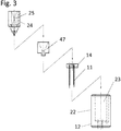
- Example 1 “Electroporation electrode having a plurality of electrode needles” As an embodiment of the electrode according to the present invention, an electrode for electroporation (1) shown in FIGS. 1 to 13 was produced. Hereinafter, the electrode for electroporation (1) manufactured in the present embodiment will be described with reference to exploded views and structural drawings.
- the electrode for electroporation includes a scarlet needle (diameter 0.26 mm, needle length 8.5 mm) made of stainless steel as the first polarity electrode needle (11), and the three electrode needles.
- a scarlet needle (diameter 0.26 mm, needle length 8.5 mm) made of stainless steel as the first polarity electrode needle (11), and the three electrode needles.
- the first polarity electrode needle (11) was inserted and fixed in a direction perpendicular to the bottom surface of the electrode needle through hole (13) formed in the bottom surface of the outer frame support lower structure (12) as a housing. It is a fixed electrode needle.
- the first polarity energization portion (14) is a substantially circular flat plate member having a thickness of about 1.5 mm and having a recessed connection portion (16) with a member constituting the first polarity electrode needle.
- a member made of stainless steel. The member is connected to a power source through wiring.
- An opening (15) for communicating with the syringe needle insertion / extraction path (40) is provided at the center of the first polarity energization section (14).
- the outer frame support lower structure (12) is a member that constitutes the outer frame body of the electrode according to the present embodiment, and is a member that is made of a polycarbonate resin that is an insulating material.
- the outer diameter of the outer frame support lower structure (12) is 10 mm as viewed from the bottom.
- the needle length of the first polar electrode needle (11) protruding from the bottom surface of the outer frame support lower structure (12) is the outer frame support lower structure. It is a fixed length of 5 mm from the bottom surface.
- the first polar electrode needles (11) are arranged at equal intervals on concentric circles in the bottom view of the outer frame support lower structure (12). Specifically, it is a structure arranged on a concentric circle having a radius of 1.5 mm (diameter 3 mm) from the center of the syringe needle insertion / extraction hole (46) which is the center of the concentric circle.
- the upper part of the outer frame support lower structure (12) is a member constituting the substantially cylindrical syringe head mounting part external structure (22) having an outer diameter of 10 mm.
- the internal structure of the portion is a structure that is hollowed out into a substantially cylindrical shape with an inner diameter of 6 mm.
- the syringe head mounting part internal structure (24) is embedded and held.
- the syringe head mounting portion internal structure (24) is a member made of stainless steel, and has a structure hollowed into a substantially cylindrical shape having an inner diameter of 4.4 mm and a height of 5.35 mm, and narrows downward.
- the structure is hollowed out into a substantially cylindrical shape having an inner diameter of 3.2 mm and a height of 1 mm.
- a syringe needle insertion hole (45) is formed at the center of the bottom surface of the internal structure (25).
- the syringe head mounting part internal structure (24) is a member connected to a power source via wiring.
- the lower side of the syringe mounting part internal structure (24) is connected and fixed to the outer frame support lower structure (12) via a spacer part (47) which is a collar.
- the spacer portion (47) is a member made of polycarbonate, which is an insulating material, and prevents the region energized in the second polarity from directly contacting the first polarity energizing portion (14). It functions as an insulating member.
- the electrode according to the present embodiment has a structure in which the syringe mounting portion internal structure (24) and the outer frame support lower structure (12) communicate with each other and a syringe needle insertion / extraction path (40) that is a tubular path structure is formed.
- a syringe needle insertion / exit flow path (40) is formed in the direction of the outer frame support lower structure (12) from the syringe needle insertion / extraction hole (45) in the bottom (26) of the syringe mounting portion internal structure.
- the syringe needle insertion / extraction flow path (40) forms a second polarity energization section (42) which is a straight pipe path having a tube length of 1.6 mm and a cross-sectional diameter of 0.5 mm.
- the spacer section (47) forms a tubular structure (43) so as to protect the outer wall, and the first polarity energization section (14) and The contact is prevented.
- the lower part of the syringe needle insertion / extraction path (40) is an insertion / extraction path (44) constituted by the base material of the outer frame support lower structure (12). A 1 mm syringe needle insertion hole (46) is formed.
- Example 2 “Electroporation electrode with syringe attached” An electrode for electroporation in which a commercially available syringe was attached to the electrode manufactured in the above example was assembled and manufactured.
- the syringe (50) attached a syringe for 0.5 mL insulin (manufactured by MyJector (registered trademark) Terumo Corporation) was used. Further, 29G (diameter 0.33 mm, needle length 13 mm) was used as the syringe needle (52).
- the needle length of the syringe needle (52) which is the second polar electrode needle protruding from the syringe needle insertion / extraction hole (46) of the outer frame support lower structure (12) is The fixed length was 4 mm from the bottom surface of the frame support lower structure (12). This was the needle length that was 1 mm shorter than the fixed length of 5 mm of the first polarity electrode needle (11).
- FIG. 13B shows a photographic image of the syringe-mounted electrode manufactured in this example.
- the syringe mounting can be executed only by a simple assembling operation for inserting a syringe needle.
- this electrode it is possible to apply a voltage with the first polarity and the second polarity as any one of + and ⁇ .
- Example 3 “Example of gene introduction into muscle tissue” A gene introduction test using an electrode for electroporation having an electrode needle produced in the above example was performed on muscle tissue.
- the operability of electroporation in vivo is dramatically improved, and it is also good for skeletal muscle that tends to have low introduction efficiency. It has been demonstrated that gene transfer is easily possible. Moreover, since the mounted syringe is a commercially available disposable syringe, sample filling is easy, and electroporation with reduced risk of contamination and infection was possible.
- the present invention is expected to be used in life science fields such as molecular biology, genetic engineering, and cell biology, medical fields such as medicine and drug discovery, and livestock fields such as livestock and poultry. In particular, it is expected to be effectively used in the technical field using electroporation in vivo.
- Electrode needle holder 11. First polarity electrode needle 12. Outer frame support lower structure 13. Electrode needle through hole 14. First polarity energization section 15. Opening 16. Connection unit 17. Wiring, cable 18. Wiring holder
- Syringe needle insertion path 41 Syringe needle insertion path (syringe head mounting part side) 42. Second polarity energization section 43. Syringe needle insertion path (spacer) 44. Syringe needle insertion path (outer frame support lower structure side) 45. Syringe needle insertion hole (Syringe head mounting part side) 46. Syringe needle insertion hole (outer frame support lower structure side) 47. Spacer part
Landscapes
- Health & Medical Sciences (AREA)
- Life Sciences & Earth Sciences (AREA)
- Engineering & Computer Science (AREA)
- Public Health (AREA)
- Biomedical Technology (AREA)
- Nuclear Medicine, Radiotherapy & Molecular Imaging (AREA)
- Animal Behavior & Ethology (AREA)
- General Health & Medical Sciences (AREA)
- Veterinary Medicine (AREA)
- Radiology & Medical Imaging (AREA)
- Biophysics (AREA)
- Bioinformatics & Cheminformatics (AREA)
- Surgery (AREA)
- Physics & Mathematics (AREA)
- Otolaryngology (AREA)
- Plasma & Fusion (AREA)
- Heart & Thoracic Surgery (AREA)
- Medical Informatics (AREA)
- Molecular Biology (AREA)
- Electrotherapy Devices (AREA)
- Accommodation For Nursing Or Treatment Tables (AREA)
- Infusion, Injection, And Reservoir Apparatuses (AREA)
Abstract
Priority Applications (4)
| Application Number | Priority Date | Filing Date | Title |
|---|---|---|---|
| JP2017539032A JP6292705B2 (ja) | 2016-02-22 | 2017-02-02 | エレクトロポレーション用電極 |
| CN201780011616.0A CN108778400B (zh) | 2016-02-22 | 2017-02-02 | 电穿孔用电极 |
| EP17756131.3A EP3421078B1 (fr) | 2016-02-22 | 2017-02-02 | Électrodes d'électroporation |
| US16/077,979 US11517741B2 (en) | 2016-02-22 | 2017-02-02 | Electrodes for electroporation |
Applications Claiming Priority (2)
| Application Number | Priority Date | Filing Date | Title |
|---|---|---|---|
| JP2016030984 | 2016-02-22 | ||
| JP2016-030984 | 2016-02-22 |
Publications (1)
| Publication Number | Publication Date |
|---|---|
| WO2017145689A1 true WO2017145689A1 (fr) | 2017-08-31 |
Family
ID=59685206
Family Applications (1)
| Application Number | Title | Priority Date | Filing Date |
|---|---|---|---|
| PCT/JP2017/003733 Ceased WO2017145689A1 (fr) | 2016-02-22 | 2017-02-02 | Électrodes d'électroporation |
Country Status (5)
| Country | Link |
|---|---|
| US (1) | US11517741B2 (fr) |
| EP (1) | EP3421078B1 (fr) |
| JP (2) | JP6292705B2 (fr) |
| CN (1) | CN108778400B (fr) |
| WO (1) | WO2017145689A1 (fr) |
Citations (7)
| Publication number | Priority date | Publication date | Assignee | Title |
|---|---|---|---|---|
| US4269174A (en) * | 1979-08-06 | 1981-05-26 | Medical Dynamics, Inc. | Transcutaneous vasectomy apparatus and method |
| JP2005518904A (ja) * | 2002-03-07 | 2005-06-30 | マーク アンド カンパニー インコーポレイテッド | 電気的刺激の側面を備えた臨床用注射器 |
| US20080058706A1 (en) * | 2004-06-30 | 2008-03-06 | Genetronics, Inc. | Modular electroporation device with disposable electrode and drug delivery components |
| US20090030364A1 (en) * | 2005-02-04 | 2009-01-29 | The Johns Hopkins University | Electroporation gene therapy gun system |
| JP2010051828A (ja) * | 2002-07-04 | 2010-03-11 | Inovio As | エレクトロポレーション装置及び注入装置 |
| JP2011509743A (ja) * | 2008-01-17 | 2011-03-31 | ジェネトロニクス,インコーポレイティド | 可変電流密度単一針電気穿孔システムおよび方法 |
| JP2015163230A (ja) * | 2004-06-24 | 2015-09-10 | スフェルゲン | 電気力を使用して分子を細胞に移動させるデバイス |
Family Cites Families (9)
| Publication number | Priority date | Publication date | Assignee | Title |
|---|---|---|---|---|
| US5993434A (en) | 1993-04-01 | 1999-11-30 | Genetronics, Inc. | Method of treatment using electroporation mediated delivery of drugs and genes |
| US5439440A (en) | 1993-04-01 | 1995-08-08 | Genetronics, Inc. | Electroporation system with voltage control feedback for clinical applications |
| US7171264B1 (en) * | 1999-05-10 | 2007-01-30 | Genetronics, Inc. | Intradermal delivery of active agents by needle-free injection and electroporation |
| US7245963B2 (en) * | 2002-03-07 | 2007-07-17 | Advisys, Inc. | Electrode assembly for constant-current electroporation and use |
| US6912417B1 (en) * | 2002-04-05 | 2005-06-28 | Ichor Medical Systmes, Inc. | Method and apparatus for delivery of therapeutic agents |
| US20060036210A1 (en) | 2004-06-30 | 2006-02-16 | Lei Zhang | Modular electroporation device with disposable electrode and drug delivery components |
| ITTO20110309A1 (it) | 2011-04-05 | 2012-10-06 | Igea S P A | Manipolo regolabile |
| CN103717249B (zh) | 2011-06-15 | 2017-03-22 | 克洛恩泰克制药股份公司 | 注射针和装置 |
| KR101587930B1 (ko) | 2013-12-18 | 2016-01-22 | 정헌 | 전기천공법용 전극침 일체형 침관장치 |
-
2017
- 2017-02-02 WO PCT/JP2017/003733 patent/WO2017145689A1/fr not_active Ceased
- 2017-02-02 JP JP2017539032A patent/JP6292705B2/ja active Active
- 2017-02-02 CN CN201780011616.0A patent/CN108778400B/zh active Active
- 2017-02-02 US US16/077,979 patent/US11517741B2/en active Active
- 2017-02-02 EP EP17756131.3A patent/EP3421078B1/fr active Active
-
2018
- 2018-02-06 JP JP2018018858A patent/JP6777905B2/ja active Active
Patent Citations (7)
| Publication number | Priority date | Publication date | Assignee | Title |
|---|---|---|---|---|
| US4269174A (en) * | 1979-08-06 | 1981-05-26 | Medical Dynamics, Inc. | Transcutaneous vasectomy apparatus and method |
| JP2005518904A (ja) * | 2002-03-07 | 2005-06-30 | マーク アンド カンパニー インコーポレイテッド | 電気的刺激の側面を備えた臨床用注射器 |
| JP2010051828A (ja) * | 2002-07-04 | 2010-03-11 | Inovio As | エレクトロポレーション装置及び注入装置 |
| JP2015163230A (ja) * | 2004-06-24 | 2015-09-10 | スフェルゲン | 電気力を使用して分子を細胞に移動させるデバイス |
| US20080058706A1 (en) * | 2004-06-30 | 2008-03-06 | Genetronics, Inc. | Modular electroporation device with disposable electrode and drug delivery components |
| US20090030364A1 (en) * | 2005-02-04 | 2009-01-29 | The Johns Hopkins University | Electroporation gene therapy gun system |
| JP2011509743A (ja) * | 2008-01-17 | 2011-03-31 | ジェネトロニクス,インコーポレイティド | 可変電流密度単一針電気穿孔システムおよび方法 |
Non-Patent Citations (1)
| Title |
|---|
| See also references of EP3421078A4 * |
Also Published As
| Publication number | Publication date |
|---|---|
| JP2018065038A (ja) | 2018-04-26 |
| EP3421078B1 (fr) | 2023-04-05 |
| EP3421078A4 (fr) | 2019-10-30 |
| JP6777905B2 (ja) | 2020-10-28 |
| JPWO2017145689A1 (ja) | 2018-03-08 |
| CN108778400B (zh) | 2022-02-25 |
| JP6292705B2 (ja) | 2018-03-14 |
| EP3421078A1 (fr) | 2019-01-02 |
| US11517741B2 (en) | 2022-12-06 |
| CN108778400A (zh) | 2018-11-09 |
| US20210187276A1 (en) | 2021-06-24 |
Similar Documents
| Publication | Publication Date | Title |
|---|---|---|
| US20230001190A1 (en) | Device and method for single-needle in vivo electroporation | |
| US8283171B2 (en) | Method and apparatus for avalanche-mediated transfer of agents into cells | |
| US11052245B2 (en) | Device and method for localized delivery and extraction of material | |
| JP2009527321A (ja) | 薬剤の細胞中へのアバランシェ媒介導入のための方法および装置 | |
| JP2012250044A (ja) | 電気力を使用して分子を細胞に移動させるデバイス | |
| KR102583350B1 (ko) | 지지부 및 바늘 전극을 구비하는 눈을 위한 전기 천공 기기 | |
| BR112021012548A2 (pt) | Dispositivo para eletrotransferência de tecido com o uso de um microelétrodo | |
| CA2686855C (fr) | Dispositif et procede pour electroporation in vivo a aiguille unique | |
| JP6292705B2 (ja) | エレクトロポレーション用電極 | |
| US11471674B2 (en) | Electroosmotic convection-enhanced delivery system | |
| CN117881449A (zh) | 用于电穿孔的侧端口注射装置以及相关的系统和方法 | |
| EP2319913A1 (fr) | Dispositif à réseau de champ électrique à force ultrafaible pour traitement de cellules | |
| CN214484729U (zh) | 一种动物用胸腔注射固定装置 | |
| Zou et al. | Targeted electroporation in embryonic, larval, and adult zebrafish | |
| Schmeer | Electroporative gene transfer | |
| Tang | Editorial (Hot Topic: Electroporation for Drug and Gene Delivery in Cancer Therapy) | |
| HK40111522A (zh) | 用於电穿孔的侧端口注射装置以及相关的系统和方法 |
Legal Events
| Date | Code | Title | Description |
|---|---|---|---|
| ENP | Entry into the national phase |
Ref document number: 2017539032 Country of ref document: JP Kind code of ref document: A |
|
| NENP | Non-entry into the national phase |
Ref country code: DE |
|
| WWE | Wipo information: entry into national phase |
Ref document number: 2017756131 Country of ref document: EP |
|
| ENP | Entry into the national phase |
Ref document number: 2017756131 Country of ref document: EP Effective date: 20180924 |
|
| 121 | Ep: the epo has been informed by wipo that ep was designated in this application |
Ref document number: 17756131 Country of ref document: EP Kind code of ref document: A1 |