WO2017146209A1 - Condenseur, et installation de turbine à vapeur doté dudit condenseur - Google Patents
Condenseur, et installation de turbine à vapeur doté dudit condenseur Download PDFInfo
- Publication number
- WO2017146209A1 WO2017146209A1 PCT/JP2017/007100 JP2017007100W WO2017146209A1 WO 2017146209 A1 WO2017146209 A1 WO 2017146209A1 JP 2017007100 W JP2017007100 W JP 2017007100W WO 2017146209 A1 WO2017146209 A1 WO 2017146209A1
- Authority
- WO
- WIPO (PCT)
- Prior art keywords
- steam
- heat transfer
- condenser
- intermediate cylinder
- transfer tube
- Prior art date
- Legal status (The legal status is an assumption and is not a legal conclusion. Google has not performed a legal analysis and makes no representation as to the accuracy of the status listed.)
- Ceased
Links
Images


Classifications
-
- F—MECHANICAL ENGINEERING; LIGHTING; HEATING; WEAPONS; BLASTING
- F01—MACHINES OR ENGINES IN GENERAL; ENGINE PLANTS IN GENERAL; STEAM ENGINES
- F01K—STEAM ENGINE PLANTS; STEAM ACCUMULATORS; ENGINE PLANTS NOT OTHERWISE PROVIDED FOR; ENGINES USING SPECIAL WORKING FLUIDS OR CYCLES
- F01K9/00—Plants characterised by condensers arranged or modified to co-operate with the engines
- F01K9/02—Arrangements or modifications of condensate or air pumps
-
- F—MECHANICAL ENGINEERING; LIGHTING; HEATING; WEAPONS; BLASTING
- F01—MACHINES OR ENGINES IN GENERAL; ENGINE PLANTS IN GENERAL; STEAM ENGINES
- F01D—NON-POSITIVE DISPLACEMENT MACHINES OR ENGINES, e.g. STEAM TURBINES
- F01D25/00—Component parts, details, or accessories, not provided for in, or of interest apart from, other groups
- F01D25/30—Exhaust heads, chambers, or the like
-
- F—MECHANICAL ENGINEERING; LIGHTING; HEATING; WEAPONS; BLASTING
- F01—MACHINES OR ENGINES IN GENERAL; ENGINE PLANTS IN GENERAL; STEAM ENGINES
- F01K—STEAM ENGINE PLANTS; STEAM ACCUMULATORS; ENGINE PLANTS NOT OTHERWISE PROVIDED FOR; ENGINES USING SPECIAL WORKING FLUIDS OR CYCLES
- F01K9/00—Plants characterised by condensers arranged or modified to co-operate with the engines
-
- F—MECHANICAL ENGINEERING; LIGHTING; HEATING; WEAPONS; BLASTING
- F28—HEAT EXCHANGE IN GENERAL
- F28B—STEAM OR VAPOUR CONDENSERS
- F28B1/00—Condensers in which the steam or vapour is separate from the cooling medium by walls, e.g. surface condenser
- F28B1/02—Condensers in which the steam or vapour is separate from the cooling medium by walls, e.g. surface condenser using water or other liquid as the cooling medium
-
- F—MECHANICAL ENGINEERING; LIGHTING; HEATING; WEAPONS; BLASTING
- F28—HEAT EXCHANGE IN GENERAL
- F28B—STEAM OR VAPOUR CONDENSERS
- F28B9/00—Auxiliary systems, arrangements, or devices
-
- F—MECHANICAL ENGINEERING; LIGHTING; HEATING; WEAPONS; BLASTING
- F28—HEAT EXCHANGE IN GENERAL
- F28B—STEAM OR VAPOUR CONDENSERS
- F28B9/00—Auxiliary systems, arrangements, or devices
- F28B9/02—Auxiliary systems, arrangements, or devices for feeding steam or vapour to condensers
Definitions
- the present invention relates to a condenser for condensing steam exhausted from a steam turbine, and a steam turbine plant including the same.
- This application claims priority based on Japanese Patent Application No. 2016-034231 filed in Japan on February 25, 2016, and PCT / JP2016 / 072623 filed internationally on August 2, 2016. The contents are incorporated herein.
- the steam turbine plant includes a steam turbine that is driven by steam, and a condenser that condenses the steam exhausted from the steam turbine and returns it to water.
- the steam turbine plant includes an axial exhaust steam turbine and a condenser that returns the steam exhausted from the steam turbine to water.
- the condenser includes a plurality of heat transfer tube groups, a main body cylinder that covers the plurality of heat transfer tube groups, and an intermediate cylinder that guides steam from the steam turbine into the main body cylinder.
- the intermediate cylinder is formed in a cylindrical shape around a substantially horizontal virtual axis.
- An intermediate cylinder inlet is formed at one end of the cylindrical intermediate cylinder, and an intermediate cylinder outlet is formed at the other end.
- Steam from the steam turbine flows into the intermediate cylinder from the intermediate cylinder inlet.
- the main body body includes a bottom plate, a plurality of side plates extending upward from an edge of the bottom plate, and a top plate.
- a main body cylinder inlet is formed in a side plate on the steam turbine side of the main body cylinder.
- the steam from the intermediate cylinder flows into the main body cylinder from the main body inlet. In other words, steam flows into the main body body from substantially the horizontal direction.
- a plurality of heat transfer tube groups arranged in the horizontal direction and a plurality of heat transfer tube groups arranged in the vertical direction are arranged in the main body trunk.
- the condenser described in Patent Document 1 has a plurality of heat transfer tube groups arranged in the vertical direction. For this reason, the cooling water pump that supplies the cooling water to the plurality of heat transfer tubes constituting the heat transfer tube group can supply the cooling water to the heat transfer tube arranged at the top of the heat transfer tube group in the uppermost direction.
- the technique described in Patent Document 1 requires a cooling water pump with a high head, which increases initial costs and running costs.
- an object of the present invention is to provide a condenser that can suppress initial costs and running costs, and a steam turbine plant including the same.
- a condenser as a first aspect according to the invention for achieving the above object includes a plurality of heat transfer tube groups configured of a plurality of heat transfer tubes through which cooling water that exchanges heat with steam passes, and a plurality of the heat transfer tubes.
- a main body cylinder that covers the heat pipe group; and an intermediate cylinder that is connected to the main body cylinder and guides steam into the main body cylinder.
- the intermediate cylinder is connected to the intermediate cylinder inlet that opens horizontally from the inside and into which steam flows, the intermediate cylinder outlet that opens downward from the inside and exhausts the steam, and the intermediate cylinder inlet and the intermediate cylinder outlet.
- the main body cylinder has a main body cylinder inlet that opens upward from the inside, is connected to the intermediate cylinder outlet, and into which steam from the intermediate cylinder flows.
- the plurality of heat transfer tube groups are arranged in the main body cylinder side by side in the horizontal direction.
- a near-side outlet edge which is the intermediate cylinder outlet and is an edge on the side close to the intermediate cylinder inlet in the horizontal direction, is positioned below the uppermost position in the plurality of heat transfer tube groups.
- the condenser since the plurality of heat transfer tube groups are arranged in the main body side by side in the horizontal direction, the cooling water supplied to the uppermost position and the heat transfer tube group among the plurality of heat transfer tube groups is arranged. The level difference from the water source can be reduced. Therefore, in the said condenser, the head of the cooling water pump which supplies the cooling water from a water source to a heat exchanger tube can be made low. For this reason, the said condenser can hold down the installation cost and running cost of a cooling water pump.
- the near side outlet edge of the middle trunk outlet is located below the uppermost position in the plurality of heat transfer tube groups. For this reason, in the said condenser, the installation position of the steam turbine connected to this condenser can be made low. Therefore, in the said condenser, the installation cost of a steam turbine can be held down.
- the condenser according to the second aspect is the inner surface of the intermediate cylinder forming the flow path of the intermediate cylinder in the condenser according to the first aspect, wherein the near inner surface including the near outlet edge is It is the surface which goes to the side which approaches the said intermediate body entrance, facing upwards from the said near side exit edge.
- the flow path area of the flow path on the outlet side of the intermediate cylinder can be increased in the flow path of the intermediate cylinder. For this reason, in the said condenser, it is thought that the average flow velocity of the steam which flows in into a heat exchanger tube group can be suppressed, and there exists a fixed effect in the erosion suppression of a heat exchanger tube.
- the condenser according to the third aspect is the condenser according to the first or second aspect, wherein the far-side outlet edge that is the edge on the side far from the middle-trunk inlet in the horizontal direction is the middle-trunk outlet, It is located above the uppermost position in the plurality of heat transfer tube groups.
- the middle trunk outlet edge is inclined from the far side outlet edge toward the near side outlet edge. Therefore, in the said condenser, the opening area of an intermediate body exit can be enlarged. For this reason, in the said condenser, it is thought that the average flow velocity of the steam which flows in into a heat exchanger tube group can be suppressed, and there exists a fixed effect in the erosion suppression of a heat exchanger tube.
- the condenser of the fourth aspect is the condenser according to any one of the first aspect to the third aspect, wherein a plurality of the heat transfer tube groups are disposed in the intermediate body inlet in the main body trunk. It is arranged at a position below the lower end.
- the condenser of a 5th aspect is located in the outermost part among the some heat exchanger tubes which comprise the said heat exchanger tube group in the condenser in any one of the said 1st aspect to the said 4th aspect.
- the vertical dimension of the outer shape of the tube group formed by a virtual surface circumscribing the plurality of heat transfer tubes is larger than the horizontal dimension of the outer shape of the tube group.
- the bottom surface of the outer shape of the tube group can be reduced. For this reason, in the said condenser, even if it arranges a some heat exchanger tube group in the main body trunk
- the condenser according to a sixth aspect is the condenser according to the fifth aspect, wherein the outer shape of the tube group has an upper surface facing upward and a bottom surface facing downward, and an upper portion including the upper surface in the outer shape of the tube group is The horizontal cross-sectional area gradually increases as it goes downward.
- the steam that has passed through the intermediate cylinder flows into the main body cylinder through the main body inlet. This steam flows mainly downward in the body trunk.
- the steam exchanges heat with the cooling water flowing in the plurality of heat transfer tubes constituting each heat transfer tube group in the process of flowing in the main body body.
- the efficiency of heat exchange between the steam and the cooling water in the heat transfer tubes constituting the heat transfer tube group increases as the area of the upper surface of the outer shape of the tube group facing this flow increases.
- the area of the upper surface can be made wider than when the entire upper surface is a horizontal surface. Therefore, in the condenser, the efficiency of heat exchange between the steam and the cooling water in the heat transfer tubes constituting the heat transfer tube group can be increased as compared with the case where all the upper surfaces of the tube group outer shapes are horizontal surfaces. .
- the condenser of the seventh aspect is the condenser of the sixth aspect, wherein the outer shape of the tube group of at least one of the heat transfer tube groups is the same as the center of the top surface of the uppermost surface. It is an eccentric outer shape located on the intermediate cylinder inlet side in the horizontal direction from the center of the bottom surface in the tube group outer shape.
- the steam and the cooling water in the heat transfer tube constituting the one heat transfer tube group even if the ratio of the horizontal direction component in the flow direction component of the steam flowing into the one heat transfer tube group is large.
- the efficiency of heat exchange can be increased.
- the condenser of the eighth aspect is the condenser of the seventh aspect, wherein the plurality of heat transfer tube groups are arranged in a horizontal direction and in a perspective direction with respect to the intermediate trunk inlet, and the plurality of heat transfer tube groups Of these, the outer shape of the tube group of the heat transfer tube group closest to the inlet of the intermediate body in the perspective direction is the eccentric outer shape.
- the ratio of the horizontal direction component of the steam flow direction component flowing into the heat transfer tube group closest to the middle cylinder inlet is larger than that of the steam flow direction component flowing into the other heat transfer tube group. Therefore, the efficiency of heat exchange with the cooling water in the heat transfer tubes constituting the heat transfer tube group can be increased by making the tube group outer shape of the heat transfer tube group closest to the intermediate body inlet in the perspective direction an eccentric shape. .
- the condenser according to the ninth aspect is the steam according to the fifth aspect or the sixth aspect, wherein the steam is disposed in the intermediate cylinder and gradually directs the direction of the flow of the steam flowing in from the inlet of the intermediate cylinder. Provide a guide.
- the lower component can be increased among the components in the flow direction of the steam flowing into the plurality of heat transfer tube groups. For this reason, in the said condenser, the efficiency of heat exchange with a cooling water in a heat exchanger tube which comprises steam and a heat exchanger tube group can be improved.
- a steam turbine plant as a tenth aspect according to the invention for achieving the above object includes the condenser according to any one of the first aspect to the ninth aspect, and exhausts steam into the condenser.
- the steam turbine plant of the eleventh aspect is the steam turbine plant of the tenth aspect, wherein the steam turbine is an axial exhaust steam turbine.
- the steam turbine plant of the twelfth aspect is the steam turbine plant of the tenth aspect, wherein the steam turbine is a side exhaust type steam turbine.
- the initial cost and running cost of a steam turbine plant can be suppressed.
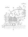
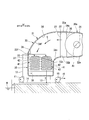
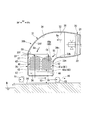
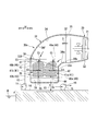
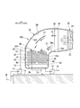
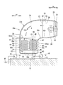
- FIG. 1 is a system diagram of a steam turbine plant in a first embodiment according to the present invention. It is typical sectional drawing of the steam turbine and condenser in 1st embodiment which concerns on this invention. It is difference explanatory drawing of the structure of the condenser in 1st embodiment which concerns on this invention, and the condenser of a comparative example. It is typical sectional drawing of the steam turbine and condenser in 2nd embodiment which concerns on this invention. It is typical sectional drawing of the condenser in the 1st modification which concerns on this invention. It is typical sectional drawing of the condenser in the 2nd modification which concerns on this invention. It is typical sectional drawing of the condenser in the 3rd modification which concerns on this invention. It is a typical sectional view of a condenser in the 4th modification concerning the present invention.
- the steam turbine plant of this embodiment includes a steam generator 17 such as a boiler, a steam turbine 20 driven by steam generated by the steam generator 17, and power generation generated by driving the steam turbine 20. , A condenser 30 for condensing the steam S exhausted from the steam turbine 20, a feed water pump 15 for returning the water in the condenser 30 to the steam generator 17, and the condenser 30 for steam cooling. A cooling water pump 11 for supplying cooling water.
- the steam generator 17 and the steam turbine 20 are connected by a main steam line 18.
- the steam generated by the steam generator 17 is supplied to the steam turbine 20 through the main steam line 18.
- the condenser 30 and the steam generator 17 are connected by a water supply line 16.
- the water supply pump 15 is provided in the water supply line 16.
- the water returned from the steam S to the liquid in the condenser 30 is supplied to the steam generator 17 through the water supply line 16.
- the steam turbine 20 includes a rotor 21 that rotates about the turbine axis At, a main body casing 22 that covers the rotor 21, and an exhaust casing 25 that exhausts steam from within the main body casing 22.
- the turbine axis At extends substantially in the horizontal direction.
- the direction in which the turbine axis At extends is defined as the axial direction Da
- one side of the axial direction Da is defined as the upstream axis Dau
- the other side is defined as the downstream axis Dad.
- the rotor 21 of the steam turbine 20 is connected to the rotor of the generator 19.
- the main casing 22 and the exhaust casing 25 are formed in a cylindrical shape around the turbine axis At.
- a steam inlet 23 is formed on the axial upstream side Dau of the cylindrical main body casing 22.
- a steam outlet 24 is formed at the end of the main body casing 22 on the downstream side of the axis Dad. The steam outlet 24 opens from the inside of the main body casing 22 toward the axial downstream side Dad.
- An exhaust steam inlet 26 is formed at an end of the exhaust casing 25 on the axial upstream side Dau. The exhaust steam inlet 26 opens from the exhaust casing 25 toward the axial upstream side Dau.
- the exhaust steam inlet 26 is connected to the steam outlet 24 of the main body casing 22.
- An exhaust steam outlet 27 is formed at the end of the exhaust casing 25 on the axial downstream side Dad.
- the exhaust steam outlet 27 opens from the exhaust casing 25 toward the axial downstream side Dad. Therefore, the steam turbine 20 is an axial exhaust type that exhausts in the axial direction Da.
- the condenser 30 includes a plurality of heat transfer tube groups 41, a main body cylinder 35 that covers the plurality of heat transfer tube groups 41, and an intermediate cylinder that guides the steam S from the steam turbine 20 into the main body cylinder 35. 31.
- the intermediate cylinder 31 includes an intermediate cylinder inlet 32 that opens in the horizontal direction from the inside and into which the steam S flows, an intermediate cylinder outlet 33 that opens downward from the inside and exhausts the steam S, and an intermediate cylinder.
- a flow path 34 that connects the inlet 32 and the intermediate trunk outlet 33 is formed.
- the flow path 34 in the intermediate cylinder 31 extends in a horizontal direction from the intermediate cylinder inlet 32 in a perspective direction Df with respect to the intermediate cylinder inlet 32, and gradually extends downward as the distance from the intermediate cylinder inlet 32 increases. It leads to the exit 33.
- the intermediate trunk inlet 32 is connected to the exhaust steam outlet 27 of the steam turbine 20. Therefore, the perspective direction Df with respect to the intermediate body inlet 32 coincides with the axial direction Da of the steam turbine 20.
- the main body body 35 includes a bottom plate 36b and side plates 36s extending upward from the edge of the bottom plate 36b. Although not shown in the figure, the main body body 35 is partitioned into a condensing chamber 37, a cooling water inlet chamber (not shown), and a cooling water outlet chamber (not shown).
- the upper part of the condensation chamber 37 is open. This opening forms a body trunk inlet 38. Therefore, the main body trunk inlet 38 opens upward from the condensation chamber 37.
- the main body trunk inlet 38 is connected to the intermediate trunk outlet 33.
- the lower part in the condensing chamber 37 constitutes a hot well 39 in which water that has become liquid by condensing the vapor S is accumulated.
- the plurality of heat transfer tube groups 41 are arranged in the condensing chamber 37 side by side in the horizontal direction. Among the plurality of heat transfer tube groups 41, any two or more heat transfer tube groups 41 are arranged in the perspective direction Df described above.
- Each of the plurality of heat transfer tube groups 41 includes a plurality of heat transfer tubes 42.
- Each heat transfer tube 42 extends in the horizontal direction.
- a three-dimensional shape formed by a virtual surface circumscribing the plurality of heat transfer tubes 42 located on the outermost side among the plurality of heat transfer tubes 42 constituting the heat transfer tube group 41 is referred to as a tube group outer shape 43.
- the tube group outer shape 43 has a bottom surface 44 facing downward, a side surface 45 extending upward from an edge of the bottom surface 44, and a top surface 46 facing upward.
- the vertical dimension of the tube group outline 43 is larger than the horizontal dimension of the tube group outline 43.
- the upper part including the upper surface 46 of the tube group outer shape 43 is gradually increased as the horizontal sectional area is directed downward. Therefore, the upper surface 46 has an inclined surface 47 that gradually decreases downward as the side surface 45 is approached.
- the center Ct of the top surface 48 that is a collection of points at the highest position in the upper surface 46 and the center Cb of the bottom surface 44 are aligned in the horizontal direction.
- the main body cylinder side in the perspective direction Df is referred to as the far side Dff
- the intermediate cylinder inlet side in the perspective direction Df is referred to as the near side Dfn.
- the near-side outlet edge 33n which is the intermediate body outlet 33 and the edge of the near side Dfn in the perspective direction Df, is located below the uppermost position in the plurality of heat transfer tube groups 41. More specifically, the near-side outlet edge 33n is located in the vicinity of the intermediate position of the heat transfer tube group 41 in the vertical direction.
- the far-side outlet edge 33f which is the intermediate body outlet 33 and the edge of the far side Dff in the perspective direction Df, is located above the uppermost position in the plurality of heat transfer tube groups 41. For this reason, the position of the edge of the intermediate body outlet 33 is gradually positioned downward from the far-side outlet edge 33f toward the near side Df.
- the uppermost position in the plurality of heat transfer tube groups 41 is the position of the top surface 48 of the tube group outer shape 43.
- the far inner surface 34f that is the inner surface of the intermediate cylinder 31 and that includes the far exit edge 33f is a surface that faces upward from the far exit edge 33f toward the near side Dfn in the perspective direction Df.
- the water supply line 16 is connected to the hot well 39 of the condenser 30.
- the cooling water pump 11 is connected to each heat transfer tube 42 constituting the plurality of heat transfer tube groups 41 via the cooling water line 12 via a cooling water inlet chamber (not shown) in the main body body 35.
- the cooling water pump 11 draws water from a water source W such as the sea or river, and supplies the water to the heat transfer tubes 42 constituting the plurality of heat transfer tube groups 41.
- Each of the heat transfer tubes 42 constituting the plurality of heat transfer tube groups 41 is connected to the drainage line 13 via a cooling water outlet chamber (not shown) in the main body body 35.
- the drain line 13 extends into the drain pit 14 or directly to the water source W.
- the drain pit 14 extends to the water source W described above, for example.
- the steam that has flowed into the main body casing 22 passes through the exhaust casing 25 and is exhausted from the exhaust steam outlet 27 of the exhaust casing 25 to the axial downstream side Dad.
- the steam S exhausted from the steam turbine 20 flows into the intermediate cylinder 31 of the condenser 30 from the intermediate cylinder inlet 32.
- the exhaust steam outlet 27 of the steam turbine 20 opens from the exhaust casing 25 in the horizontal direction (axial downstream side Dad).
- the intermediate cylinder inlet 32 connected to the exhaust steam outlet 27 opens from the intermediate cylinder 31 in the horizontal direction. Therefore, the flow direction component of the steam S flowing into the intermediate cylinder 31 has a large horizontal direction component.
- the lower component of the direction component of the flow of the steam S gradually increases.
- the steam S that has flowed into the intermediate cylinder 31 gradually flows downward in the intermediate cylinder 31 from the intermediate cylinder inlet 32 toward the intermediate cylinder outlet 33.
- the steam S that has passed through the intermediate cylinder 31 flows from the main body cylinder inlet 38 into the condensation chamber 37 of the main body cylinder 35.
- the steam S flows mainly downward in the condensation chamber 37.
- the steam S exchanges heat with the cooling water flowing in the plurality of heat transfer tubes 42 constituting each heat transfer tube group 41 in the process of flowing in the condensation chamber 37.
- the steam S is condensed by heat exchange with the cooling water flowing in the plurality of heat transfer tubes 42 constituting each heat transfer tube group 41 to be converted into water.
- This water accumulates in a hot well 39 below the condensing chamber 37.
- the water accumulated in the hot well 39 returns to the steam generator 17 through the water supply line 16 and the water supply pump 15.
- the plurality of heat transfer tube groups 41 are arranged in the horizontal direction in the main body trunk 35.
- the level difference between the heat transfer tube 42 at the highest position and the water surface of the water source W is relatively small as compared with the condenser in which the heat transfer tube group is arranged in the vertical direction. be able to. Therefore, in this embodiment, the head of the cooling water pump 11 can be lowered. For this reason, in this embodiment, the installation cost and running cost of the cooling water pump 11 can be suppressed.
- the initial cost and running cost of the steam turbine plant can be suppressed.
- the tube group outer shape 43 of the present embodiment has a horizontal dimension smaller than the vertical dimension. Therefore, in the present embodiment, the bottom surface 44 of the tube group outer shape 43 can be reduced. For this reason, in this embodiment, even if it arranges the some heat exchanger tube group 41 in the main body trunk
- the steam turbine plant of the comparative example also includes a steam turbine 20 indicated by a two-dot chain line in FIG. 3 and a condenser 30x that condenses the steam exhausted from the steam turbine 20.
- the steam turbine 20 of the comparative example is the same as the steam turbine 20 of the present embodiment.
- the condenser 30x of the comparative example is different from the condenser 30 of the present embodiment.
- the condenser 30x of the comparative example also includes a plurality of heat transfer tube groups 41, a main body cylinder 35x that covers the plurality of heat transfer pipe groups 41, and an intermediate cylinder 31x that guides the steam S from the steam turbine 20 into the main body cylinder 35x. Prepare.
- the intermediate cylinder 31x includes an intermediate cylinder inlet 32x that opens from the inside in the horizontal direction and into which the steam S flows, an intermediate cylinder outlet 33x that opens downward from the inside and exhausts the steam S, and an intermediate cylinder A flow path 34x that connects the inlet 32x and the intermediate trunk outlet 33x is formed.
- the flow path 34x in the intermediate cylinder 31x extends in a horizontal direction from the intermediate cylinder inlet 32x in a perspective direction Df with respect to the intermediate cylinder inlet 32x, and gradually extends downward as the distance from the intermediate cylinder inlet 32x increases. It leads to the exit 33x.
- the intermediate trunk inlet 32 x is connected to the exhaust steam outlet 27 of the steam turbine 20.
- the intermediate trunk outlet 33x is connected to the body trunk inlet 38x of the body trunk 35x.
- the above configuration relating to the intermediate cylinder 31x of the comparative example is the same as the configuration of the intermediate cylinder 31 of the present embodiment.
- the middle cylinder outlet 33x which is the edge of the near side Dfn in the perspective direction Df
- the near side outlet edge 33nx which is the middle cylinder outlet 33x
- the distance of the far side Dff in the perspective direction Df The position in the vertical direction is the same as that of the side outlet edge 33fx.
- the entire edge of the intermediate body outlet 33x is located above the uppermost position in the plurality of heat transfer tube groups 41. Note that the far-side exit edge 33fx of the comparative example and the far-side exit edge 33f of the present embodiment have the same vertical position.
- the vertical distance from the lower end 32bx of the intermediate cylinder inlet 32x of the comparative example to the near-side outlet edge 33nx of the intermediate cylinder outlet 33x is the lower side of the intermediate cylinder inlet 32 of the present embodiment to the near side of the intermediate cylinder outlet 33. It is assumed that the distance is the same as the vertical distance to the outlet edge 33n. In this case, since the near side outlet edge 33n of the present embodiment is positioned below the near side outlet edge 33nx of the comparative example in the vertical direction, the lower end 32b of the intermediate trunk inlet 32 of the present embodiment This is located below the lower end 32bx of the intermediate body inlet 32x of the comparative example.
- the steam turbine 20 connected to the intermediate cylinder inlet 32 is positioned below the steam turbine 20 connected to the intermediate cylinder inlet 32x in the comparative example. For this reason, in this embodiment, the installation cost of the steam turbine 20 can be held down rather than a comparative example. Therefore, in this embodiment, the initial cost of the steam turbine plant can be suppressed also from this viewpoint.
- the position of the edge of the intermediate body outlet 33 is gradually positioned downward as it goes from the far side outlet edge 33f toward the near side Df.
- the edge of the intermediate body outlet 33 is inclined from the far-side outlet edge 33f toward the near-side outlet edge 33n. Therefore, in this embodiment, the opening area of the intermediate trunk outlet 33 can be increased.
- the near-side outlet edge 33n of the intermediate cylinder outlet 33 is positioned below the uppermost position in the plurality of heat transfer tube groups 41, and the near-side inner surface 34n of the intermediate cylinder 31 is positioned on the near side. While facing upward from the outlet edge 33n, it faces the near side Dfn in the perspective direction Df.
- the flow path area of the flow path on the intermediate cylinder outlet 33 side in the flow path 34 in the intermediate cylinder 31 is increased.
- the average flow velocity of the steam flowing into the heat transfer tube group 41 can be suppressed as compared with the comparative example, and it is considered that there is a certain effect in suppressing the erosion of the heat transfer tube 42.
- the steam turbine plant of this embodiment also includes a steam turbine 20a and a condenser 30 as in the steam turbine plant of the first embodiment.
- the steam turbine 20a of the present embodiment also has a rotor 21 that rotates around the turbine axis At, a main body casing 22a that covers the rotor 21, and steam from within the main body casing 22a. And an exhaust casing 25a for exhausting.
- the main casing 22a is formed in a cylindrical shape around the turbine axis At.
- a steam inlet (not shown) is formed on the upstream side of the axial line of the cylindrical main body casing 22a.
- a steam outlet 24a is formed on the downstream side of the axial line of the cylindrical main body casing 22a.
- the steam outlet 24a is different from the steam outlet 24 of the first embodiment, and opens from the inside of the main body casing 22a to the side.
- the exhaust casing 25a is formed in a cylindrical shape around an axis that is perpendicular to the turbine axis At and faces in the horizontal direction.
- An exhaust steam inlet 26 is formed at one end of the exhaust casing 25a in the axial direction.
- An exhaust steam outlet 27 is formed at the other end in the axial direction of the exhaust casing 25a. Both the exhaust steam inlet 26 and the exhaust steam outlet 27 are open from the inside of the exhaust casing 25a in the horizontal direction.
- the exhaust steam inlet 26 is connected to the steam outlet 24a of the main body casing 22a.
- the steam turbine 20a of the present embodiment is a side exhaust type steam turbine that exhausts steam to a side perpendicular to the turbine axis At.
- the condenser 30 of the present embodiment includes a plurality of heat transfer tube groups 41, a main body trunk 35 that covers the plurality of heat transfer tube groups 41, and steam from the steam turbine 20a. And an intermediate cylinder 31 for guiding S into the main body cylinder 35.
- the plurality of heat transfer tube groups 41, the main body cylinder 35, and the intermediate cylinder 31 in the present embodiment are basically the same as the plurality of heat transfer tube groups 41, the main body cylinder 35, and the intermediate cylinder 31 in the first embodiment, respectively.
- the intermediate cylinder 31 of the present embodiment also has an intermediate cylinder inlet 32 that opens from the inside in the horizontal direction and into which the steam S flows, and an intermediate cylinder outlet that opens downward from the inside and discharges the steam S. 33 and a flow path 34 that connects the intermediate cylinder inlet 32 and the intermediate cylinder outlet 33 are formed.
- the flow path 34 in the intermediate cylinder 31 extends from the intermediate cylinder inlet 32 in the horizontal direction and in the perspective direction Df with respect to the intermediate cylinder inlet 32, and extends downward as the distance from the intermediate cylinder inlet 32 increases. 33.
- the intermediate trunk inlet 32 is connected to the exhaust steam outlet 27 of the steam turbine 20a. Therefore, the perspective direction Df with respect to the intermediate body inlet 32 is different from the first embodiment in the horizontal direction perpendicular to the turbine axis At.
- the condenser 30 of the present embodiment is the same as the condenser 30 of the first embodiment. Therefore, also in this embodiment, the initial cost and running cost of the steam turbine plant can be suppressed.
- the tube group outer shape 43 has a horizontal dimension smaller than the vertical dimension. Therefore, also in this embodiment, the increase in the occupation area of the condenser 30 can be suppressed.
- the tube group outer shape 43a of the heat transfer tube group 41a disposed on the closest side Dfn is deformed in the perspective direction Df with respect to the intermediate trunk inlet 32 among the plurality of heat transfer tube groups 41. ing.
- the center Ct of the top surface 48a of the tube group outer shape 43a of the heat transfer tube group 41a on the near side Dfn is positioned closer to the near side Dfn than the center Cb of the bottom surface 44 of the tube group outer shape 43a. Therefore, this tube group outer shape 43a becomes an eccentric outer shape.
- the lower component is the steam St flowing into the main body body 35 from the near side Dfn portion than the steam Sa flowing into the main body body 35 from the far side Dfn portion. Is also small.
- the horizontal direction component is the steam Sa flowing into the main body body 35 from the portion on the near side Dfn and flowing into the main body body 35 from the portion on the far side Dfn. Bigger than.
- the heat transfer tube group 41a disposed on the near side Dfn is closer to the main body from the portion on the near side Dfn than the steam St flowing into the main body body 35 from the portion on the far side Dfn.
- the amount of contact with the steam St that has flowed into the body 35 is large.
- the tube group outer shape 43a of the heat transfer tube group 41a disposed on the near side Dfn is made an eccentric outer shape as described above, so that the heat transfer tube group 41a constituting the heat transfer tube group 41a has The efficiency of heat exchange between the cooling water and the steam S is increased.
- this modification is a modification of 1st embodiment, you may comprise the heat exchanger tube group 41 of the near side Dfn of said 2nd embodiment similarly to this modification.
- the heat transfer tube group 41a on the closest side Dfn out of the plurality of heat transfer tube groups 41 has an eccentric outer shape.
- the far side Dfn heat transfer tube group 41b may also have an eccentric outer shape.
- the distance in the perspective direction Df from the center Cb of the bottom surface 44 in the tube group outer shape 43a of the heat transfer tube group 41a on the near side Dfn to the center Ct of the top surface 48a of the tube group outer shape 43a is defined as an eccentricity amount ⁇ a.
- the distance in the perspective direction Df from the center Cb of the bottom surface 44 of the tube group outer shape 43b of the heat transfer tube group 41b on the far side Dfn to the center Ct of the top surface 48b of the tube group outer shape 43b is defined as an eccentricity amount ⁇ b.
- the eccentric amount ⁇ b in the tube group outer shape 43b of the heat transfer tube group 41b is set to the tube group outer shape of the near side Dfn heat transfer tube group 41a. It may be smaller than the amount of eccentricity ⁇ a at 43a. In other words, the amount of eccentricity ⁇ a in the tube group outer shape 43a of the heat transfer tube group 41a on the near side Dfn may be larger than the amount of eccentricity ⁇ b in the tube group outer shape 43b of the heat transfer tube group 41b on the far side Dfn.
- this modification is a modification of 1st embodiment, you may comprise the some heat exchanger tube group 41 of said 2nd embodiment similarly to this modification.
- the condenser 30d of the present modification includes a steam guide 51 which is disposed in the intermediate cylinder 31 and gradually directs the flow direction of the steam S flowing from the intermediate cylinder inlet 32 downward.
- the steam guide 51 is gradually bent downward toward the far side Dfn in the perspective direction Df.
- the lower component of the components in the flow direction of the steam S flowing into the main body cylinder 35 from the main body inlet 38 can be made larger than the same component in the first embodiment. For this reason, in this modification, the efficiency of heat exchange between the cooling water and the steam S in the heat transfer tubes 42 constituting each heat transfer tube group 41 can be increased.
- this modification is a modification of 1st embodiment, you may comprise the condenser of said 2nd embodiment similarly to this modification.
- the uppermost position in the plurality of heat transfer tube groups 41 is above the lower end 32 b of the intermediate trunk inlet 32.
- the uppermost position in the plurality of heat transfer tube groups 41 is above the lower end 32 b of the intermediate trunk inlet 32.
- the plurality of heat transfer tube groups 41 are arranged at positions below the lower end 32 b of the intermediate body inlet 32.
- the position of the near side outlet edge 33ne of the intermediate body outlet 33 in the intermediate body 31e is set to the near side outlet of the intermediate body outlet 33 of the first embodiment. It is higher than the position of the edge 33n.
- the shape of the main body cylinder 35e of the present modification is also slightly different from the shape of the main body cylinder 35 of the first embodiment.
- the installation position of the steam turbine 20 is increased.
- the position of the far side outlet edge 33fe of the intermediate trunk outlet 33 is the same as the position of the far side outlet edge 33f of the intermediate trunk outlet 33 of the first embodiment in the vertical direction.
- the plurality of heat transfer tube groups 41 are disposed at positions below the lower end 32b of the intermediate body inlet 32, the steam that has traveled straight from the steam turbine 20 in the horizontal direction is directly transferred to the heat transfer tube group 41. It is considered that the occurrence of erosion of the heat transfer tube 42 can be suppressed as compared with the first embodiment.
- the installation position of the steam turbine 20 is increased. Therefore, whether the uppermost position in the plurality of heat transfer tube groups 41 is higher or lower than the lower end 32b of the intermediate trunk inlet 32 suppresses the occurrence of erosion of the heat transfer tubes 42 and the steam turbine 20. It should be decided by which one to place emphasis on lowering the installation position.
- the gas turbine combined cycle plant includes a steam turbine plant including a steam turbine and a condenser. Therefore, you may apply this invention to the condenser of a gas turbine combined cycle.
- the initial cost and running cost of a steam turbine plant can be suppressed.
- Cooling water pump 12 Cooling water line 13: Drainage line 14: Drainage pit 15: Water supply pump 16: Water supply line 17: Steam generator 18: Main steam line 19: Generator 20, 20a: Steam turbine 21: Rotor 22 22a: body casing 23: steam inlet 24, 24a: steam outlet 25, 25a: exhaust casing 26: exhaust steam inlet 27: exhaust steam outlets 30, 30a, 30b, 30c, 30d, 30e: condensers 31, 31e: Intermediate cylinder 32: Intermediate cylinder inlet 32b: Lower end 33: Intermediate cylinder outlet 33f, 33fe: Far side outlet edge 33n, 33ne: Near side outlet edge 34: Channel 34f: Far side inner surface 34n: Near side inner surface 35, 35e: Main body Cylinder 36b: Bottom plate 36s: Side plate 37: Condensing chamber 38: Body trunk inlet 39: Hot wells 41, 41a, 41b: Heat transfer tube group 42: Heat transfer tubes 43, 43 a, 43b: Tube group shape 44: Bottom surface 45: Side surface 46: Top surface 47: Hot well
Landscapes
- Engineering & Computer Science (AREA)
- Mechanical Engineering (AREA)
- General Engineering & Computer Science (AREA)
- Chemical & Material Sciences (AREA)
- Combustion & Propulsion (AREA)
- Engine Equipment That Uses Special Cycles (AREA)
Abstract
Priority Applications (5)
| Application Number | Priority Date | Filing Date | Title |
|---|---|---|---|
| US15/999,818 US10760452B2 (en) | 2016-02-25 | 2017-02-24 | Condenser and steam turbine plant provided with same |
| DE112017001010.1T DE112017001010T5 (de) | 2016-02-25 | 2017-02-24 | Kondensator und mit demselben versehene dampfturbinenanlage |
| CN201780012143.6A CN108700382B (zh) | 2016-02-25 | 2017-02-24 | 冷凝器以及具备该冷凝器的蒸汽涡轮设备 |
| KR1020187023812A KR102064153B1 (ko) | 2016-02-25 | 2017-02-24 | 복수기, 및 이것을 구비하는 증기 터빈 플랜트 |
| JP2018501793A JP6578609B2 (ja) | 2016-02-25 | 2017-02-24 | 復水器、及びこれを備える蒸気タービンプラント |
Applications Claiming Priority (4)
| Application Number | Priority Date | Filing Date | Title |
|---|---|---|---|
| JP2016-034231 | 2016-02-25 | ||
| JP2016034231 | 2016-02-25 | ||
| JPPCT/JP2016/072623 | 2016-08-02 | ||
| PCT/JP2016/072623 WO2017145404A1 (fr) | 2016-02-25 | 2016-08-02 | Condenseur et installation de turbine à vapeur pourvue de celui-ci |
Publications (1)
| Publication Number | Publication Date |
|---|---|
| WO2017146209A1 true WO2017146209A1 (fr) | 2017-08-31 |
Family
ID=59685009
Family Applications (2)
| Application Number | Title | Priority Date | Filing Date |
|---|---|---|---|
| PCT/JP2016/072623 Ceased WO2017145404A1 (fr) | 2016-02-25 | 2016-08-02 | Condenseur et installation de turbine à vapeur pourvue de celui-ci |
| PCT/JP2017/007100 Ceased WO2017146209A1 (fr) | 2016-02-25 | 2017-02-24 | Condenseur, et installation de turbine à vapeur doté dudit condenseur |
Family Applications Before (1)
| Application Number | Title | Priority Date | Filing Date |
|---|---|---|---|
| PCT/JP2016/072623 Ceased WO2017145404A1 (fr) | 2016-02-25 | 2016-08-02 | Condenseur et installation de turbine à vapeur pourvue de celui-ci |
Country Status (6)
| Country | Link |
|---|---|
| US (1) | US10760452B2 (fr) |
| JP (1) | JP6578609B2 (fr) |
| KR (1) | KR102064153B1 (fr) |
| CN (1) | CN108700382B (fr) |
| DE (1) | DE112017001010T5 (fr) |
| WO (2) | WO2017145404A1 (fr) |
Families Citing this family (1)
| Publication number | Priority date | Publication date | Assignee | Title |
|---|---|---|---|---|
| CN119630868A (zh) * | 2022-06-19 | 2025-03-14 | 曹一丁 | 空气-水热能发电厂 |
Citations (8)
| Publication number | Priority date | Publication date | Assignee | Title |
|---|---|---|---|---|
| JPS51137008A (en) * | 1975-05-21 | 1976-11-26 | Hitachi Ltd | A steam condenser |
| JPH09273875A (ja) * | 1996-04-02 | 1997-10-21 | Mitsubishi Heavy Ind Ltd | 蒸気タービンの復水装置 |
| JP2003302175A (ja) * | 2002-04-09 | 2003-10-24 | Mitsubishi Heavy Ind Ltd | 復水器及び蒸気タービン設備及びガスタービン設備及び原子力設備 |
| US20050109032A1 (en) * | 2003-11-07 | 2005-05-26 | Harpster Joseph W. | Condensers and their monitoring |
| JP2010276020A (ja) * | 2009-05-28 | 2010-12-09 | General Electric Co <Ge> | 蒸気タービン二流式低圧構成 |
| US8567177B1 (en) * | 2012-11-30 | 2013-10-29 | Yoganeck, LLC | Gas turbine engine system with water recycling feature |
| JP2014066390A (ja) * | 2012-09-25 | 2014-04-17 | Toshiba Corp | 軸流排気式復水器 |
| JP2014190590A (ja) * | 2013-03-27 | 2014-10-06 | Mitsubishi Heavy Ind Ltd | 復水器、及びこれを備える蒸気タービンプラント |
Family Cites Families (16)
| Publication number | Priority date | Publication date | Assignee | Title |
|---|---|---|---|---|
| GB190907321A (en) | 1909-03-26 | 1910-06-27 | Donald Barns Morison | Improvements in and connected with Apparatus for Condensing Steam. |
| GB215356A (en) | 1923-04-30 | 1925-07-29 | Luther Daniel Lovekin | Improvements in surface condensers |
| US2939685A (en) | 1955-12-14 | 1960-06-07 | Lummus Co | Condenser deaerator |
| DE1501339A1 (de) | 1966-04-02 | 1969-12-04 | Weser Ag | Dampfkondensator |
| IL88571A (en) * | 1988-12-02 | 1998-06-15 | Ormat Turbines 1965 Ltd | Method of and apparatus for producing power using steam |
| DE19642100B4 (de) * | 1996-10-12 | 2011-09-29 | Alstom | Dampfkondensator |
| US6276442B1 (en) * | 1998-06-02 | 2001-08-21 | Electric Boat Corporation | Combined condenser/heat exchanger |
| JP2000304464A (ja) * | 1999-04-15 | 2000-11-02 | Toshiba Corp | 復水器 |
| EP1126227A1 (fr) * | 2000-02-09 | 2001-08-22 | ALSTOM POWER (Schweiz) AG | Condenseur de vapeur |
| JP5403978B2 (ja) * | 2008-09-16 | 2014-01-29 | 三菱重工業株式会社 | 復水器 |
| KR20130057728A (ko) * | 2011-11-24 | 2013-06-03 | 주남식 | 응축 터빈을 이용한 발전 장치 |
| JP5978435B2 (ja) * | 2012-10-11 | 2016-08-24 | 三菱日立パワーシステムズ株式会社 | 復水器 |
| JP6092062B2 (ja) * | 2013-09-24 | 2017-03-08 | 株式会社東芝 | 蒸気弁装置及び発電設備 |
| WO2016046685A1 (fr) | 2014-09-26 | 2016-03-31 | Semiconductor Energy Laboratory Co., Ltd. | Dispositif d'imagerie |
| JP6419562B2 (ja) * | 2014-12-10 | 2018-11-07 | 株式会社東芝 | 水平流入型復水器 |
| JP6061014B2 (ja) | 2015-11-24 | 2017-01-18 | 日本電気株式会社 | 非接触型充電器 |
-
2016
- 2016-08-02 WO PCT/JP2016/072623 patent/WO2017145404A1/fr not_active Ceased
-
2017
- 2017-02-24 WO PCT/JP2017/007100 patent/WO2017146209A1/fr not_active Ceased
- 2017-02-24 DE DE112017001010.1T patent/DE112017001010T5/de not_active Ceased
- 2017-02-24 JP JP2018501793A patent/JP6578609B2/ja not_active Expired - Fee Related
- 2017-02-24 KR KR1020187023812A patent/KR102064153B1/ko not_active Expired - Fee Related
- 2017-02-24 US US15/999,818 patent/US10760452B2/en not_active Expired - Fee Related
- 2017-02-24 CN CN201780012143.6A patent/CN108700382B/zh not_active Expired - Fee Related
Patent Citations (8)
| Publication number | Priority date | Publication date | Assignee | Title |
|---|---|---|---|---|
| JPS51137008A (en) * | 1975-05-21 | 1976-11-26 | Hitachi Ltd | A steam condenser |
| JPH09273875A (ja) * | 1996-04-02 | 1997-10-21 | Mitsubishi Heavy Ind Ltd | 蒸気タービンの復水装置 |
| JP2003302175A (ja) * | 2002-04-09 | 2003-10-24 | Mitsubishi Heavy Ind Ltd | 復水器及び蒸気タービン設備及びガスタービン設備及び原子力設備 |
| US20050109032A1 (en) * | 2003-11-07 | 2005-05-26 | Harpster Joseph W. | Condensers and their monitoring |
| JP2010276020A (ja) * | 2009-05-28 | 2010-12-09 | General Electric Co <Ge> | 蒸気タービン二流式低圧構成 |
| JP2014066390A (ja) * | 2012-09-25 | 2014-04-17 | Toshiba Corp | 軸流排気式復水器 |
| US8567177B1 (en) * | 2012-11-30 | 2013-10-29 | Yoganeck, LLC | Gas turbine engine system with water recycling feature |
| JP2014190590A (ja) * | 2013-03-27 | 2014-10-06 | Mitsubishi Heavy Ind Ltd | 復水器、及びこれを備える蒸気タービンプラント |
Also Published As
| Publication number | Publication date |
|---|---|
| JPWO2017146209A1 (ja) | 2019-01-17 |
| CN108700382B (zh) | 2019-08-30 |
| US10760452B2 (en) | 2020-09-01 |
| CN108700382A (zh) | 2018-10-23 |
| DE112017001010T5 (de) | 2018-11-22 |
| KR20180100691A (ko) | 2018-09-11 |
| KR102064153B1 (ko) | 2020-01-08 |
| US20190331005A1 (en) | 2019-10-31 |
| WO2017145404A1 (fr) | 2017-08-31 |
| JP6578609B2 (ja) | 2019-09-25 |
Similar Documents
| Publication | Publication Date | Title |
|---|---|---|
| US20170059251A1 (en) | Deaerator | |
| JP6578609B2 (ja) | 復水器、及びこれを備える蒸気タービンプラント | |
| JP5984687B2 (ja) | 湿分分離加熱器、及びこれを備える湿分分離加熱設備 | |
| CN101326589A (zh) | 气水分离器 | |
| JP4796146B2 (ja) | 湿分分離器 | |
| CN101435348A (zh) | 内置除氧装置的空冷汽轮机排汽装置 | |
| CN101743437A (zh) | 蒸汽发生器 | |
| CN104279886A (zh) | 直接空冷凝结水集箱降温系统 | |
| JP5645538B2 (ja) | 脱気器 | |
| JP2013148296A (ja) | 復水器及び復水システム、並びに発電設備 | |
| KR101777524B1 (ko) | 공랭식 열교환기를 가지는 피동보조급수계통 | |
| JP2002081612A (ja) | 給水加熱器 | |
| KR101551822B1 (ko) | 증기발생기 및 이를 구비하는 원전 | |
| JP2008298326A (ja) | 熱交換器および温水装置 | |
| JP3944227B1 (ja) | 湿分分離加熱器 | |
| JP6589719B2 (ja) | 空冷式復水装置 | |
| JP6789855B2 (ja) | 復水器及び発電プラント用タービンシステム | |
| KR20170027021A (ko) | 탈기기 | |
| JP6081110B2 (ja) | 複合復水器 | |
| JP2013066841A (ja) | 多重効用造水装置における分割バンドルによる蒸気流制御システム | |
| CN210602344U (zh) | 一种用于超高温热泵机组的水冷冷凝器 | |
| JP2012063119A (ja) | 湿分分離加熱器 | |
| JP2008144716A (ja) | 湿分分離器 | |
| JP5802630B2 (ja) | 蒸気タービン設備 | |
| JP2024154908A (ja) | 熱交換器 |
Legal Events
| Date | Code | Title | Description |
|---|---|---|---|
| ENP | Entry into the national phase |
Ref document number: 20187023812 Country of ref document: KR Kind code of ref document: A |
|
| WWE | Wipo information: entry into national phase |
Ref document number: 1020187023812 Country of ref document: KR |
|
| WWE | Wipo information: entry into national phase |
Ref document number: 2018501793 Country of ref document: JP |
|
| 121 | Ep: the epo has been informed by wipo that ep was designated in this application |
Ref document number: 17756643 Country of ref document: EP Kind code of ref document: A1 |
|
| 122 | Ep: pct application non-entry in european phase |
Ref document number: 17756643 Country of ref document: EP Kind code of ref document: A1 |