WO2017154782A1 - Structure d'admission de moteur à combustion interne - Google Patents
Structure d'admission de moteur à combustion interne Download PDFInfo
- Publication number
- WO2017154782A1 WO2017154782A1 PCT/JP2017/008537 JP2017008537W WO2017154782A1 WO 2017154782 A1 WO2017154782 A1 WO 2017154782A1 JP 2017008537 W JP2017008537 W JP 2017008537W WO 2017154782 A1 WO2017154782 A1 WO 2017154782A1
- Authority
- WO
- WIPO (PCT)
- Prior art keywords
- intake
- inlet pipe
- partition plate
- cylinder head
- combustion engine
- Prior art date
- Legal status (The legal status is an assumption and is not a legal conclusion. Google has not performed a legal analysis and makes no representation as to the accuracy of the status listed.)
- Ceased
Links
Images




Classifications
-
- F—MECHANICAL ENGINEERING; LIGHTING; HEATING; WEAPONS; BLASTING
- F02—COMBUSTION ENGINES; HOT-GAS OR COMBUSTION-PRODUCT ENGINE PLANTS
- F02F—CYLINDERS, PISTONS OR CASINGS, FOR COMBUSTION ENGINES; ARRANGEMENTS OF SEALINGS IN COMBUSTION ENGINES
- F02F1/00—Cylinders; Cylinder heads
- F02F1/24—Cylinder heads
- F02F1/42—Shape or arrangement of intake or exhaust channels in cylinder heads
- F02F1/4235—Shape or arrangement of intake or exhaust channels in cylinder heads of intake channels
- F02F1/4242—Shape or arrangement of intake or exhaust channels in cylinder heads of intake channels with a partition wall inside the channel
-
- F—MECHANICAL ENGINEERING; LIGHTING; HEATING; WEAPONS; BLASTING
- F02—COMBUSTION ENGINES; HOT-GAS OR COMBUSTION-PRODUCT ENGINE PLANTS
- F02B—INTERNAL-COMBUSTION PISTON ENGINES; COMBUSTION ENGINES IN GENERAL
- F02B31/00—Modifying induction systems for imparting a rotation to the charge in the cylinder
- F02B31/04—Modifying induction systems for imparting a rotation to the charge in the cylinder by means within the induction channel, e.g. deflectors
-
- F—MECHANICAL ENGINEERING; LIGHTING; HEATING; WEAPONS; BLASTING
- F02—COMBUSTION ENGINES; HOT-GAS OR COMBUSTION-PRODUCT ENGINE PLANTS
- F02M—SUPPLYING COMBUSTION ENGINES IN GENERAL WITH COMBUSTIBLE MIXTURES OR CONSTITUENTS THEREOF
- F02M35/00—Combustion-air cleaners, air intakes, intake silencers, or induction systems specially adapted for, or arranged on, internal-combustion engines
- F02M35/10—Air intakes; Induction systems
- F02M35/10006—Air intakes; Induction systems characterised by the position of elements of the air intake system in direction of the air intake flow, i.e. between ambient air inlet and supply to the combustion chamber
- F02M35/10072—Intake runners
-
- F—MECHANICAL ENGINEERING; LIGHTING; HEATING; WEAPONS; BLASTING
- F02—COMBUSTION ENGINES; HOT-GAS OR COMBUSTION-PRODUCT ENGINE PLANTS
- F02M—SUPPLYING COMBUSTION ENGINES IN GENERAL WITH COMBUSTIBLE MIXTURES OR CONSTITUENTS THEREOF
- F02M35/00—Combustion-air cleaners, air intakes, intake silencers, or induction systems specially adapted for, or arranged on, internal-combustion engines
- F02M35/10—Air intakes; Induction systems
- F02M35/10006—Air intakes; Induction systems characterised by the position of elements of the air intake system in direction of the air intake flow, i.e. between ambient air inlet and supply to the combustion chamber
- F02M35/10078—Connections of intake systems to the engine
- F02M35/10085—Connections of intake systems to the engine having a connecting piece, e.g. a flange, between the engine and the air intake being foreseen with a throttle valve, fuel injector, mixture ducts or the like
-
- F—MECHANICAL ENGINEERING; LIGHTING; HEATING; WEAPONS; BLASTING
- F02—COMBUSTION ENGINES; HOT-GAS OR COMBUSTION-PRODUCT ENGINE PLANTS
- F02M—SUPPLYING COMBUSTION ENGINES IN GENERAL WITH COMBUSTIBLE MIXTURES OR CONSTITUENTS THEREOF
- F02M35/00—Combustion-air cleaners, air intakes, intake silencers, or induction systems specially adapted for, or arranged on, internal-combustion engines
- F02M35/10—Air intakes; Induction systems
- F02M35/10242—Devices or means connected to or integrated into air intakes; Air intakes combined with other engine or vehicle parts
- F02M35/10262—Flow guides, obstructions, deflectors or the like
-
- F—MECHANICAL ENGINEERING; LIGHTING; HEATING; WEAPONS; BLASTING
- F02—COMBUSTION ENGINES; HOT-GAS OR COMBUSTION-PRODUCT ENGINE PLANTS
- F02M—SUPPLYING COMBUSTION ENGINES IN GENERAL WITH COMBUSTIBLE MIXTURES OR CONSTITUENTS THEREOF
- F02M35/00—Combustion-air cleaners, air intakes, intake silencers, or induction systems specially adapted for, or arranged on, internal-combustion engines
- F02M35/16—Combustion-air cleaners, air intakes, intake silencers, or induction systems specially adapted for, or arranged on, internal-combustion engines characterised by use in vehicles
- F02M35/162—Motorcycles; All-terrain vehicles, e.g. quads, snowmobiles; Small vehicles, e.g. forklifts
-
- F—MECHANICAL ENGINEERING; LIGHTING; HEATING; WEAPONS; BLASTING
- F02—COMBUSTION ENGINES; HOT-GAS OR COMBUSTION-PRODUCT ENGINE PLANTS
- F02M—SUPPLYING COMBUSTION ENGINES IN GENERAL WITH COMBUSTIBLE MIXTURES OR CONSTITUENTS THEREOF
- F02M35/00—Combustion-air cleaners, air intakes, intake silencers, or induction systems specially adapted for, or arranged on, internal-combustion engines
- F02M35/10—Air intakes; Induction systems
- F02M35/1015—Air intakes; Induction systems characterised by the engine type
- F02M35/1017—Small engines, e.g. for handheld tools, or model engines; Single cylinder engines
-
- F—MECHANICAL ENGINEERING; LIGHTING; HEATING; WEAPONS; BLASTING
- F02—COMBUSTION ENGINES; HOT-GAS OR COMBUSTION-PRODUCT ENGINE PLANTS
- F02M—SUPPLYING COMBUSTION ENGINES IN GENERAL WITH COMBUSTIBLE MIXTURES OR CONSTITUENTS THEREOF
- F02M35/00—Combustion-air cleaners, air intakes, intake silencers, or induction systems specially adapted for, or arranged on, internal-combustion engines
- F02M35/10—Air intakes; Induction systems
- F02M35/10242—Devices or means connected to or integrated into air intakes; Air intakes combined with other engine or vehicle parts
- F02M35/10288—Air intakes combined with another engine part, e.g. cylinder head cover or being cast in one piece with the exhaust manifold, cylinder head or engine block
-
- Y—GENERAL TAGGING OF NEW TECHNOLOGICAL DEVELOPMENTS; GENERAL TAGGING OF CROSS-SECTIONAL TECHNOLOGIES SPANNING OVER SEVERAL SECTIONS OF THE IPC; TECHNICAL SUBJECTS COVERED BY FORMER USPC CROSS-REFERENCE ART COLLECTIONS [XRACs] AND DIGESTS
- Y02—TECHNOLOGIES OR APPLICATIONS FOR MITIGATION OR ADAPTATION AGAINST CLIMATE CHANGE
- Y02T—CLIMATE CHANGE MITIGATION TECHNOLOGIES RELATED TO TRANSPORTATION
- Y02T10/00—Road transport of goods or passengers
- Y02T10/10—Internal combustion engine [ICE] based vehicles
- Y02T10/12—Improving ICE efficiencies
Definitions
- the present invention relates to an intake structure for an internal combustion engine in which a partition plate portion is formed integrally with an intake port.
- an inlet pipe is connected to an intake port of a cylinder head to form a continuous intake passage.
- a partition plate portion is provided in the intake passage, the intake passage is divided into a tumble flow path and a main flow path, and is divided into two parts.
- the intake air from the open / close valve of the carburetor is guided to the tumble flow path at the time of low load of the internal combustion engine to promote the generation of the tumble flow, and the intake air is mainly guided to the main flow path at the time of high load, for example, the following patent It is shown in Document 1.
- the cylinder head and the inlet pipe may be made of different materials, and the partition plate portion of the intake passage is provided separately on the cylinder head side and the inlet pipe side. Therefore, the partition plate portion on the intake port side of the cylinder head may be cast integrally with the cylinder head.
- the partition plate portion and the inlet pipe mounting portion as in the prior art, there is a problem that the flowability of the hot water during casting deteriorates in the thin partition plate portion. there were.
- the mold for forming the above-mentioned space for removing the meat absorbs the heat of the molten metal that is about to flow to the partition plate portion, and the molten aluminum may be solidified before the molten metal flows to the partition plate portion. .
- the present invention has been made in view of the above prior art, and in a cylinder head in which a partition plate portion is formed integrally with an intake port, it is easy to maintain the heat of the molten metal at the time of casting and improve the flowability of the molten metal at the time of casting. It is an object of the present invention to provide an intake structure for an internal combustion engine.
- the inner surface of the combustion chamber ceiling wall of the cylinder head is opposed to the top surface of the piston that is slidably fitted in the cylinder bore of the cylinder block.
- a combustion chamber is formed between the intake valve port and the exhaust valve port that are opened on the inner surface of the combustion chamber ceiling wall of the cylinder head, and the intake port and the exhaust port are curved and extended in directions away from each other.
- An inlet pipe is connected to the intake port to form a continuous intake passage, and the intake passage is partitioned into a first intake passage and a second intake passage by a partition plate portion, and the partition plate portion in the intake port is
- the cylinder head has a connection surface portion with the inlet pipe, and the connection surface portion includes an inlet pipe.
- An inlet pipe mounting portion into which a mounting fastening member is screwed is formed, and the inlet pipe mounting portion and the partition plate portion of the intake port are integrally formed, and at least a part of the inlet pipe mounting portion is
- An intake structure for an internal combustion engine is provided in which an upstream end face of the intake port is located on an extension in a direction extending across the intake port.
- the inlet pipe mounting portion and the partition plate portion are integrally connected by the connecting portion.
- the connecting portion may be such that the partition plate portion is on an extension line extending in the left-right direction across the intake port.
- the cylinder head has a spark plug mounting portion on the outer surface side of the combustion chamber ceiling wall, and a hollow portion is provided in the vicinity of the spark plug mounting portion. Has an opening on the inlet pipe mounting portion side of the hollow portion, and the opening is offset from the inlet pipe mounting portion.
- the partition plate portion and the inlet pipe mounting portion can be brought close to each other so as to have a volume at the gathered place. This makes it easier to maintain the heat of the molten metal during casting and improves the flowability of the molten metal during casting.
- the structural continuity between the partition plate and the inlet pipe mounting portion allows the inlet pipe mounting portion to be maintained. The rigidity around is improved.
- the molten metal at the time of casting can be handed over to the partition plate portion via the connecting portion that connects the inlet pipe mounting portion and the partition plate portion, and the inlet pipe mounting portion and It is possible to prevent the heat of the molten metal from being absorbed by the mold for forming the lightening space as in the case where the lightening space is formed between the partition plate and the flow of hot water to the partition plate. Can be improved.
- the opening area of the opening of the hollow portion can be increased, and the cylinder head Cooling around the spark plug mounting portion can be performed satisfactorily.
- FIG. 1 is a right side view of a scooter type motorcycle equipped with a power unit having an intake structure for an internal combustion engine according to an embodiment of the present invention.
- FIG. 2 is a rear right side view of the scooter type motorcycle of FIG. 1 with a vehicle body cover removed.
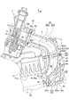
- FIG. 3 is a side cross-sectional view of the internal combustion engine portion of the power unit shown in FIG. 2 with the same orientation as shown in FIG. 2. It is a principal part enlarged view of FIG. It is a left view of the shell of a cylinder head, and the left side in the figure is the front of the vehicle.
- FIG. 6 is a top view of the shell of the cylinder head, taken along the line VI-VI in FIG. 5.
- FIG. 5 is a top view of the shell of the cylinder head, taken along the line VI-VI in FIG. 5.
- FIG. 6 is a plan cross-sectional view of the shell of the cylinder head as viewed in the direction of arrows VII-VII in FIG. 5.
- FIG. 6 is a top perspective view of a cylinder head shell as viewed in the direction of arrow VIII in FIG. 5.
- FIG. 8 is a front cross-sectional view of the shell of the Linda head, as viewed in the direction of arrows IX-IX in FIGS. 6 and 7.
- an intake structure for an internal combustion engine will be described with reference to the drawings.
- the directions such as front, rear, left, right, up, down, and the like are in accordance with the direction of the vehicle on which the internal combustion engine including the intake structure according to the present embodiment is mounted.
- the vehicle is a small vehicle, for example, a scooter type motorcycle.
- an arrow FR indicates the front of the vehicle
- LH indicates the left side of the vehicle
- RH indicates the right side of the vehicle
- UP indicates the upper side of the vehicle.
- FIG. 1 shows a right side surface of a scooter type motorcycle (hereinafter simply referred to as “motorcycle”) 1 equipped with a power unit composed of an internal combustion engine of the present embodiment.
- a vehicle body front portion 1A and a vehicle body rear portion 1B are connected via a low floor portion 1C, and a vehicle body frame 2 forming a skeleton of the vehicle body is generally composed of a down tube 21 and a main pipe 22 (see FIG. 2). ). That is, the down tube 21 extends downward from the head pipe 20 of the vehicle body front portion 1A, the down tube 21 is bent horizontally at the lower end and extends rearward below the floor portion 1C, and as shown in FIG.
- a pair of left and right main pipes 22 are connected via a connecting frame 23 arranged in the vehicle width direction at the end, and the main pipe 22 rises obliquely rearward from the connecting frame 23 and bends so that the inclination is loosened in the middle. Extending backwards.
- the main pipe 22 supports the occupant seat 11, a storage case below the occupant seat, a fuel tank, and the like, and the lower portion of the occupant seat 11 is covered with a vehicle body cover 12.
- a handle 13 is provided above and supported by the head pipe 20, a front fork 14 extends downward, and a front wheel 15 is supported at the lower end thereof.
- the power unit 3 is a single-cylinder four-stroke cycle air-cooled internal combustion engine (hereinafter simply referred to as “internal combustion engine”) 30, and the power unit 3 includes a crankshaft at the front of the power unit case 50 constituting the crankcase 50 a. 51 is arranged in the vehicle width direction and is rotatably supported, and the cylinder axis X is in a posture that is largely inclined forward to a substantially horizontal state. An end portion of the hanger arm 52 protruding forward from the lower end of the power unit case 50 is connected through a link member 25 attached to the bracket 24 of the main pipe 22.
- internal combustion engine internal combustion engine
- the power unit 3 has an internal combustion engine 30 that is largely inclined forward substantially horizontally at a front portion of the power unit case 50 constituting the crankcase portion 50a.
- a cylinder block 31, a cylinder head 32, and a cylinder head cover 33 constituting the internal combustion engine 30 are fastened so as to be stacked in order, and a power transmission case portion 55 having a belt type continuously variable transmission or the like from the crankcase portion 50a to the left rear is provided.
- a rear axle 56 that is an output shaft of the power unit 3 is provided at a rear portion thereof, and a rear wheel 16 is attached thereto.
- a rear cushion (not shown) is interposed between the power transmission case 55 at the rear of the power unit 3 and the rear of the main pipe 22.
- the inlet pipe 6 extends from the upper part of the cylinder head 32 inclined largely forward of the internal combustion engine 30, curves backward, and is connected to the inlet pipe 6. Is located above the cylinder block 31, and an air cleaner device (not shown) is disposed above the power transmission case 55 in the carburetor 7 via a connecting tube 37.
- the exhaust pipe 38 extending downward from the lower part of the cylinder head 32 is bent rearward, is biased to the right and extends rearward, and is connected to the muffler 39 on the right side of the rear wheel 16.
- FIG. 3 is a side sectional view of the front portion of the power unit 3, that is, the portion of the internal combustion engine 30, with the same orientation as shown in FIG.
- a connecting rod 35 connects a piston 34 that reciprocates in a cylinder bore 31 a of a cylinder block 31 and a crank pin 51 a of a crankshaft 51.
- a combustion chamber 36 is provided between the top surface 34a of the piston 34 slidably fitted in the cylinder bore 31a of the cylinder block 31 and the inner surface 32ai of the combustion chamber ceiling wall 32a of the cylinder head 32 opposed to the top surface 34a. Is configured.
- the internal combustion engine 30 employs an SOHC type two-valve system, and the valve mechanism 9 is provided in the cylinder head 32.
- the cylinder head 32 is covered with a cylinder head cover 33 so as to cover the valve mechanism 9.
- an endless cam chain (not shown) is provided on one side of the crankcase 50a, the cylinder block 31, and the cylinder head 32 in the direction of the crankshaft 51. Passing through the chamber 96 (see FIG. 9), the camshaft 91 is installed between the camshaft 91 and the crankshaft 51, and the camshaft 91 rotates in synchronization with the crankshaft 51 at a half rotational speed.
- a spark plug (not shown) is inserted into the spark plug mounting portion 32b (see FIG. 9) from the opposite side of the cam chain chamber 96 (the other side in the direction of the crankshaft 51) into the combustion chamber 36. ing.
- the intake valve port 40 and the exhaust valve port 41 opened on the inner surface 32ai of the combustion chamber ceiling wall 32 a are each inhaled.
- the port 42 and the exhaust port 43 are formed so as to extend while being curved away from each other in the vertical direction.
- An upstream end face 42 a of the intake port 42 is connected to the inlet pipe 6 toward the upper side of the cylinder head 32 to form a continuous intake passage 80, and the carburetor 7 is connected to the upstream side of the inlet pipe 6. .
- the downstream end of the exhaust port 43 is connected to the exhaust pipe 38 toward the lower side of the cylinder head 32.
- a cylindrical valve guide 44 is integrally fitted to the curved outer wall portion of the intake port 42 in the cylinder head 32, and the intake valve 46 slidably supported by the valve guide 44 faces the combustion chamber 36 of the intake port 42. Open and close the intake valve port 40.
- an exhaust valve 47 slidably supported by a valve guide 45 fitted integrally with the curved outer wall portion of the exhaust port 43 in the cylinder head 32 has an exhaust valve port 41 facing the combustion chamber 36 of the exhaust port 43. Open and close.
- the intake valve 46 and the exhaust valve 47 are biased upward by the valve spring 48 so that the umbrella portions 46a and 47a close the intake valve port 40 and the exhaust valve port 41 facing the combustion chamber 36, respectively.
- the valve 46 and the exhaust valve 47 are opened, and the intake port 42 and the combustion chamber 36 communicate with each other, and the exhaust port 43 and the combustion chamber 36 communicate with each other to perform intake and exhaust at a predetermined timing.
- the intake passage 80 is provided to give a tumble flow of the fuel / air mixture, that is, longitudinal rotation, in the combustion chamber 36 so as to obtain more preferable combustion in the combustion chamber 36. Is formed. That is, the intake passage 80 is divided into the first intake passage 80A and the second intake passage 80B by the partition plate portion 85 from the inlet pipe 6 to the intake port 42.
- the second intake passage 80B is a lower lower passage close to the lower end 71a when the on-off valve 71 of the carburetor 7 is closed, and serves as a tumble passage.
- the first intake passage 80A is an upper upper passage excluding the second intake passage 80B and serves as a main flow passage.
- the flow path 70 of the vaporizer 7 is connected to the connecting tube 37 on the upstream side, and the downstream end 70 a is connected to the upstream end of the inlet pipe 6 via the insulator 75. 6a, that is, connected to the upstream end 80a of the intake passage 80.
- an on-off valve 71 formed by a venturi piston of the venturi section 72 is provided in the middle of the flow path 70.
- the carburetor 7 is provided with a throttle valve 73 (FIG. 3) on the upstream side of the on-off valve 71 to constitute a negative pressure operation type carburetor.
- the on-off valve 71 is pressed against the lower end of the channel 70 to close the channel 70.
- the air is sucked out and becomes a mixture with the intake air, and is sent from the flow path 70 on the downstream side of the vaporizer 7 to the inlet pipe 6, that is, to the intake passage 80.
- a mixture of intake air and fuel (hereinafter simply referred to as “intake air”) flowing into the intake passage when the internal combustion engine is under low load is a lower end 71a of the gate valve 71 having a small opening and a bottom portion 70b of the flow path 70.
- intake air A mixture of intake air and fuel flowing into the intake passage when the internal combustion engine is under low load
- the air flows out in a fan shape along the bottom 70b from between the air and the intake passage 80.
- the intake air easily flows into the second intake passage 80B, and the second intake passage 80B has the intake air over the back side of the umbrella portion 46a of the opened intake valve 46.
- a tumble flow can be easily generated in the combustion chamber 36.
- the opening / closing valve 71 of the carburetor 7 increases, and most of the intake air flows through the first intake passage 80A, so that the flow rate flowing through the second intake passage 80B is reduced.
- the intake air flowing through the first intake passage 80A and the second intake passage 80B can be prevented from colliding downstream of the intake passage 80, that is, downstream of the intake port 42.
- the intake port 42 and the inlet pipe 6 are connected via an insulator 60.
- the partition plate portion 85 includes an inlet pipe side partition plate portion 85A, an intake port side partition plate portion 85B, and a partition plate portion 85C corresponding to the thickness of the insulator 60.
- the partition plate portion 85 in the intake port 42 of the present embodiment, that is, the intake port side partition plate portion 85B is formed integrally with the cylinder head 32.
- FIG. 5 is a left side view of the shell of the cylinder head when viewed from the side opposite to FIGS. 3 and 4 which are right side cross-sectional views, and the left side in the figure is the front of the vehicle.
- the cylinder head 32 is provided with a planar connection surface portion 100 for attaching the inlet pipe 6 with the insulator 60 interposed therebetween.
- FIG. 6 which is a top view of the shell of the cylinder head 32 as viewed in the direction of arrows VI-VI in FIG. 5, the surface of the connection surface portion 100 is formed in a flange shape of a pipe joint.
- an inlet pipe first mounting portion 101 is formed as an inlet pipe mounting portion on the left side of the connecting surface portion 100, and the inlet on the right side.
- a pipe second attachment portion 102 is formed.
- the inlet pipe first mounting portion 101 is provided with a left female screw hole 105 into which a fastening bolt 103 as a fastening member of the inlet pipe 6 is screwed, and the inlet pipe second mounting portion 102 is screwed with the fastening bolt 103.
- a right female screw hole 106 is provided.
- the right side portion 100b of the connecting surface portion 100 where the inlet pipe second mounting portion 102 is located is a top perspective view of the shell of the cylinder head 32 as viewed in the direction of arrow VIII in FIG.
- the shell body bulges and is formed by the shell body of the cylinder head 32 itself. Therefore, the inlet pipe second mounting portion 102 is a part of the shell body of the cylinder head 32, and the right female screw hole 106 is formed in the shell body of the cylinder head 32 from the right side portion 100 ⁇ / b> B of the connection surface portion 100.
- the left side portion 100A of the connection surface portion 100 where the inlet pipe first mounting portion 101 is located is integrally formed with the cylinder head 32 as shown in FIG. It is formed by a flange-like portion 104 extending from the outer surface of the shell body. Accordingly, the left female screw hole 105 into which the fastening bolt 103 is screwed is formed in a boss-like portion 107 that protrudes from the outer surface of the shell body of the cylinder head 32 and reaches the left side portion 100A of the connection surface portion 100.
- the inlet pipe first mounting portion 101 is integrally formed so as to protrude from the outer surface of the shell body of the cylinder head 32 to reach the left side portion 100A of the connection surface portion 100 and to integrate the cylinder head 32 and the left side portion 100A.
- a boss 107 is included.
- an upstream end face 42a of the intake port 42 opens substantially upward in the left and right center of the connection surface portion 100, and a first intake passage 80A is formed in the front portion (upper portion shown in FIG. 6).
- the second intake passage 80B is formed in the rear portion (lower portion in FIG. 6), and the partition plate portion 85 (85B) of the intake port 42 is formed therebetween.
- the inlet pipe first and second attachment portions 101 and 102 located on the left and right sides of the connection surface portion 100 are provided substantially symmetrically with respect to the center of the opening of the intake port 42.
- the inlet pipe first mounting portion 101 is closer to the second intake passage 80B side than the center of the opening of the intake port 42, and the partition plate portion 85 (85B)
- the front-rear position and the direction extending left and right across the intake port 42 are substantially the same.
- the inlet pipe first mounting portion 101 of the connection surface portion 100 and the partition plate portion 85 (85B) of the intake port 42 are integrally formed and the inlet pipe first mounting portion 101 (particularly, the region of the female screw hole 105). ) Is located on the upstream end face 42a of the intake port 42 on an extension in the direction in which the partition plate portion 85 (85B) extends across the intake port 42.
- the following effects can be obtained. That is, in the cylinder head 32 in which the partition plate portion 85 (85B) is integrally formed with the intake port 42, the volume of the partition plate portion 85 (85B) and the inlet pipe first mounting portion 101 can be increased.
- the increased volume makes it easier to maintain the heat of the molten metal during casting, improving the flowability of the molten metal during casting, and the structural continuity of the partition plate 85 (85B) and the inlet pipe first mounting portion 101. Therefore, the rigidity around the inlet pipe first mounting portion 101 is improved.
- the inlet pipe second mounting portion 102 is formed by a shell body that is formed by the shell body of the cylinder head 32 bulging, and the flowability and rigidity of the member during casting of the inlet pipe second mounting portion 102 are as follows. It is good.
- FIG. 7 which is a plan sectional view of the shell of the cylinder head 32 as viewed in the direction of arrows VII-VII in FIG. 5, the female screw hole 106 on the right side is a shell of the cylinder head 32 that becomes the inlet pipe second mounting portion 102. Although it is opened in the main body, the left female screw hole 105 is opened in a boss 107 that forms a part of the inlet pipe first mounting portion 101 behind the right female screw hole 106 (downward in FIG. 7). .
- the periphery of the boss-shaped portion 107 has been conventionally used as a space for lightening (reducing thickness to reduce weight) and formed away from the periphery of the intake port 42.
- the boss-like portion 107 forming a part of the inlet pipe first mounting portion 101 and the partition plate portion 85 (85B) are integrally connected at the shortest distance by the connecting portion 108. It is shaped as follows.
- the connecting portion 108 is on an extension line in the direction in which the partition plate portion 85B extends left and right across the intake port 42.
- the intermediate portion of the connecting portion 108 has a thickness substantially corresponding to the thickness of the partition plate portion 85 (85B).
- the connecting portion 108 By positioning the connecting portion 108 on the extension line in the direction in which the partition plate portion 85B extends to the left and right across the intake port 42, the volume of the entire portion including the boss 107 and the connecting portion 108 is maintained, and at the time of casting In addition, it is possible to ensure hot water flowing through the connecting portion 108.
- the molten metal at the time of casting the cylinder head body is transferred from the cylinder head body casting mold space to the communication part via the connecting part 108 that connects the inlet pipe first mounting part 101 and the partition plate part 85 (85B) at the shortest. It can be distributed to the partition plate portion 85 (85B) through the connecting portion 108 that acts as the above. Also, the heat of the molten metal is absorbed by the mold for forming the lightening space as in the case where the lightening space is formed between the inlet pipe first mounting portion 101 and the partition plate portion 85 (85B). The hot water flow to the partition plate portion 85 can be improved.
- FIG. 9 is a front sectional view of the shell of the Linda head 32 taken in the direction of arrows IX-IX in FIGS. 6 and 7 (orientation looking down from above the intake port 42 located above).
- the cylinder head 32 is provided with a cavity portion 32c in the vicinity of the spark plug mounting portion 32b on the outer surface 32ao side of the combustion chamber ceiling wall 32a.
- the hollow portion 32c is provided for air cooling of the cylinder head 32.
- the hollow portion 32c is formed on the right side of the spark plug mounting portion 32b, the upper intake port 42 opening side (lower side in FIG. 9), and the lower portion.
- An opening is provided on the opening side of the exhaust port 43 (upper side in FIG. 9) to promote the circulation of outside air.
- the opening on the opening side of the intake port 42 of the cavity 32c in the cylinder head 32, that is, the opening 32d on the inlet pipe first mounting portion 101 side is along the peripheral wall 42b of the intake port 42 as shown in FIGS. It opens to the front of the inlet pipe first mounting portion 101 (upper side of FIGS. 6 and 7).
- the boss 107 constituting the inlet pipe first mounting portion 101 is located rearward (downward in FIG. 7) from the center of the intake port 42 and is generally the partition plate portion 85 (85B). ) On the side.
- the opening 32d on the inlet pipe first mounting portion 101 side of the cavity portion 32c in the cylinder head 32 is offset from the inlet pipe first mounting portion 101, the opening area of the opening 32d of the cavity portion 32c is increased. Therefore, the circulation of the outside air becomes good, and the cooling around the spark plug mounting portion 32b of the cylinder head 32 can be performed well.
- the aspect of the present invention is not limited to the above-described embodiment, and it is needless to say that the present invention includes those implemented in various aspects within the scope of the gist of the present invention.
- the carburetor is disposed upstream of the inlet pipe, but the present invention is applied to an intake structure in which a throttle body is disposed upstream of the inlet pipe and a fuel injection valve is disposed downstream of the throttle body.
- the power unit having the internal combustion engine in which the cylinder axis X is tilted substantially horizontally and forward has been described with respect to the left and right arrangements shown in the figure.
- the vehicle, power unit, different types of the internal combustion engine, Even those having different left and right arrangements are included in the present invention within the scope of the gist of the invention.
- SYMBOLS 1 ... Motorcycle (scooter type motorcycle), 2 ... Body frame, 3 ... Power unit, 6 ... Inlet pipe, 30 ... Internal combustion engine (air-cooled internal combustion engine), 31 ... Cylinder block, 31a ... Cylinder bore, 32 ... Cylinder head, 32a ... Combustion chamber ceiling wall, 32ai ... inner surface, 32ao ... outer surface, 32b ... spark plug mounting portion, 32c ... hollow portion, 32d ... opening (on the inlet pipe first mounting portion 101 side of the hollow portion 32c), 34 ... piston, 34a ... Top surface, 36 ... Combustion chamber, 40 ... Intake valve port, 41 ... Exhaust valve port, 42 ...
Landscapes
- Engineering & Computer Science (AREA)
- Chemical & Material Sciences (AREA)
- Combustion & Propulsion (AREA)
- Mechanical Engineering (AREA)
- General Engineering & Computer Science (AREA)
- Cylinder Crankcases Of Internal Combustion Engines (AREA)
Abstract
Priority Applications (3)
| Application Number | Priority Date | Filing Date | Title |
|---|---|---|---|
| CN201780015703.3A CN108779736B (zh) | 2016-03-09 | 2017-03-03 | 内燃机的进气构造 |
| EP17763122.3A EP3428433B1 (fr) | 2016-03-09 | 2017-03-03 | Structure d'admission de moteur à combustion interne |
| JP2018504449A JP6574543B2 (ja) | 2016-03-09 | 2017-03-03 | 内燃機関の吸気構造 |
Applications Claiming Priority (2)
| Application Number | Priority Date | Filing Date | Title |
|---|---|---|---|
| JP2016-045800 | 2016-03-09 | ||
| JP2016045800 | 2016-03-09 |
Publications (1)
| Publication Number | Publication Date |
|---|---|
| WO2017154782A1 true WO2017154782A1 (fr) | 2017-09-14 |
Family
ID=59789301
Family Applications (1)
| Application Number | Title | Priority Date | Filing Date |
|---|---|---|---|
| PCT/JP2017/008537 Ceased WO2017154782A1 (fr) | 2016-03-09 | 2017-03-03 | Structure d'admission de moteur à combustion interne |
Country Status (4)
| Country | Link |
|---|---|
| EP (1) | EP3428433B1 (fr) |
| JP (1) | JP6574543B2 (fr) |
| CN (1) | CN108779736B (fr) |
| WO (1) | WO2017154782A1 (fr) |
Cited By (3)
| Publication number | Priority date | Publication date | Assignee | Title |
|---|---|---|---|---|
| WO2020179694A1 (fr) * | 2019-03-01 | 2020-09-10 | 本田技研工業株式会社 | Structure d'admission d'air pour moteur à combustion interne |
| JPWO2021186513A1 (fr) * | 2020-03-16 | 2021-09-23 | ||
| JPWO2023053378A1 (fr) * | 2021-09-30 | 2023-04-06 |
Families Citing this family (2)
| Publication number | Priority date | Publication date | Assignee | Title |
|---|---|---|---|---|
| EP3650679B1 (fr) * | 2017-07-05 | 2023-03-08 | Honda Motor Co., Ltd. | Structure d'admission d'air destinée à un moteur à combustion interne |
| WO2019009348A1 (fr) * | 2017-07-05 | 2019-01-10 | 本田技研工業株式会社 | Structure d'admission de moteur à combustion interne |
Citations (4)
| Publication number | Priority date | Publication date | Assignee | Title |
|---|---|---|---|---|
| JP2002501829A (ja) * | 1998-01-31 | 2002-01-22 | フオルクスワーゲン・アクチエンゲゼルシヤフト | 内燃機関のシリンダヘッドを製造する方法 |
| JP2003239750A (ja) * | 2002-02-13 | 2003-08-27 | Nissan Motor Co Ltd | 内燃機関の吸気装置 |
| JP2009180225A (ja) * | 2008-01-30 | 2009-08-13 | Andreas Stihl Ag & Co Kg | 弾性のあるコネクタを備えた内燃エンジンおよび弾性のあるコネクタを製造するための方法 |
| JP2015190373A (ja) * | 2014-03-28 | 2015-11-02 | 本田技研工業株式会社 | 内燃機関の吸気構造 |
Family Cites Families (4)
| Publication number | Priority date | Publication date | Assignee | Title |
|---|---|---|---|---|
| JPS58138255A (ja) * | 1982-02-13 | 1983-08-17 | Honda Motor Co Ltd | エンジンの吸気装置 |
| JP4657177B2 (ja) * | 2006-08-29 | 2011-03-23 | 本田技研工業株式会社 | 内燃機関 |
| CN101634270B (zh) * | 2008-07-24 | 2012-01-04 | 雅马哈发动机株式会社 | 车辆用发动机单元和具有该发动机单元的跨乘式车辆 |
| CN206860281U (zh) * | 2016-12-01 | 2018-01-09 | Tvs电机股份有限公司 | 稀燃式内燃发动机及其转接器 |
-
2017
- 2017-03-03 JP JP2018504449A patent/JP6574543B2/ja active Active
- 2017-03-03 EP EP17763122.3A patent/EP3428433B1/fr active Active
- 2017-03-03 WO PCT/JP2017/008537 patent/WO2017154782A1/fr not_active Ceased
- 2017-03-03 CN CN201780015703.3A patent/CN108779736B/zh active Active
Patent Citations (4)
| Publication number | Priority date | Publication date | Assignee | Title |
|---|---|---|---|---|
| JP2002501829A (ja) * | 1998-01-31 | 2002-01-22 | フオルクスワーゲン・アクチエンゲゼルシヤフト | 内燃機関のシリンダヘッドを製造する方法 |
| JP2003239750A (ja) * | 2002-02-13 | 2003-08-27 | Nissan Motor Co Ltd | 内燃機関の吸気装置 |
| JP2009180225A (ja) * | 2008-01-30 | 2009-08-13 | Andreas Stihl Ag & Co Kg | 弾性のあるコネクタを備えた内燃エンジンおよび弾性のあるコネクタを製造するための方法 |
| JP2015190373A (ja) * | 2014-03-28 | 2015-11-02 | 本田技研工業株式会社 | 内燃機関の吸気構造 |
Cited By (8)
| Publication number | Priority date | Publication date | Assignee | Title |
|---|---|---|---|---|
| WO2020179694A1 (fr) * | 2019-03-01 | 2020-09-10 | 本田技研工業株式会社 | Structure d'admission d'air pour moteur à combustion interne |
| JPWO2020179694A1 (fr) * | 2019-03-01 | 2020-09-10 | ||
| JP7229334B2 (ja) | 2019-03-01 | 2023-02-27 | 本田技研工業株式会社 | 内燃機関の吸気構造 |
| JPWO2021186513A1 (fr) * | 2020-03-16 | 2021-09-23 | ||
| JP7336587B2 (ja) | 2020-03-16 | 2023-08-31 | 本田技研工業株式会社 | 内燃機関の吸気構造 |
| JPWO2023053378A1 (fr) * | 2021-09-30 | 2023-04-06 | ||
| WO2023053378A1 (fr) * | 2021-09-30 | 2023-04-06 | 本田技研工業株式会社 | Structure d'admission d'air pour moteur à combustion interne |
| JP7575615B2 (ja) | 2021-09-30 | 2024-10-29 | 本田技研工業株式会社 | 内燃機関の吸気構造 |
Also Published As
| Publication number | Publication date |
|---|---|
| EP3428433A1 (fr) | 2019-01-16 |
| CN108779736B (zh) | 2020-10-27 |
| JPWO2017154782A1 (ja) | 2018-11-29 |
| CN108779736A (zh) | 2018-11-09 |
| EP3428433A4 (fr) | 2019-02-27 |
| JP6574543B2 (ja) | 2019-09-11 |
| EP3428433B1 (fr) | 2020-02-19 |
Similar Documents
| Publication | Publication Date | Title |
|---|---|---|
| JP3911950B2 (ja) | 自動二輪車 | |
| JP6574543B2 (ja) | 内燃機関の吸気構造 | |
| CN100582453C (zh) | 车辆用内燃机 | |
| JP6714764B2 (ja) | 内燃機関の吸気構造 | |
| US7163074B2 (en) | Motorcycle and engine for motorcycle | |
| JP2010159703A (ja) | シリンダヘッドの冷却構造 | |
| JPS6069256A (ja) | 自動二輪車の吸気装置 | |
| JP7336587B2 (ja) | 内燃機関の吸気構造 | |
| CN102278226B (zh) | 内燃机的气缸盖结构 | |
| JP6215807B2 (ja) | 内燃機関の吸気装置 | |
| JP4602235B2 (ja) | 内燃機関と自動二輪車 | |
| US7565897B2 (en) | Internal combustion engine | |
| JP6592391B2 (ja) | 空冷式内燃機関 | |
| JP7256924B2 (ja) | 鞍乗型車両用内燃機関の吸気制御装置 | |
| JP2004314679A (ja) | 自動二輪車の吸気装置 | |
| JPH0380963B2 (fr) | ||
| CN111608817B (zh) | 鞍乘型车辆用内燃机 | |
| JP3965888B2 (ja) | V型エンジンの二次空気供給装置 | |
| JP4549240B2 (ja) | 小型車両の内燃機関 | |
| WO2024202016A1 (fr) | Structure d'entrée d'air pour moteur à combustion interne | |
| JP6186299B2 (ja) | 鞍乗り型車両の吸気構造 | |
| JP2007120480A (ja) | 2次空気供給装置とブリーザ装置とを備える内燃機関 | |
| JPH0340230B2 (fr) | ||
| JP2020148184A (ja) | エアクリーナ内のファンネル構造 | |
| JP2001234810A (ja) | 水冷式4サイクル多気筒エンジンのシリンダヘッド |
Legal Events
| Date | Code | Title | Description |
|---|---|---|---|
| DPE1 | Request for preliminary examination filed after expiration of 19th month from priority date (pct application filed from 20040101) | ||
| WWE | Wipo information: entry into national phase |
Ref document number: 2018504449 Country of ref document: JP |
|
| NENP | Non-entry into the national phase |
Ref country code: DE |
|
| WWE | Wipo information: entry into national phase |
Ref document number: 2017763122 Country of ref document: EP |
|
| ENP | Entry into the national phase |
Ref document number: 2017763122 Country of ref document: EP Effective date: 20181009 |
|
| 121 | Ep: the epo has been informed by wipo that ep was designated in this application |
Ref document number: 17763122 Country of ref document: EP Kind code of ref document: A1 |