WO2017159574A1 - 心機能測定装置、心機能測定方法および心機能測定プログラム - Google Patents
心機能測定装置、心機能測定方法および心機能測定プログラム Download PDFInfo
- Publication number
- WO2017159574A1 WO2017159574A1 PCT/JP2017/009785 JP2017009785W WO2017159574A1 WO 2017159574 A1 WO2017159574 A1 WO 2017159574A1 JP 2017009785 W JP2017009785 W JP 2017009785W WO 2017159574 A1 WO2017159574 A1 WO 2017159574A1
- Authority
- WO
- WIPO (PCT)
- Prior art keywords
- cardiac function
- shape
- complexity
- unit
- jugular vein
- Prior art date
- Legal status (The legal status is an assumption and is not a legal conclusion. Google has not performed a legal analysis and makes no representation as to the accuracy of the status listed.)
- Ceased
Links
Images




Classifications
-
- A—HUMAN NECESSITIES
- A61—MEDICAL OR VETERINARY SCIENCE; HYGIENE
- A61B—DIAGNOSIS; SURGERY; IDENTIFICATION
- A61B5/00—Measuring for diagnostic purposes; Identification of persons
- A61B5/02—Detecting, measuring or recording for evaluating the cardiovascular system, e.g. pulse, heart rate, blood pressure or blood flow
- A61B5/02007—Evaluating blood vessel condition, e.g. elasticity, compliance
-
- A—HUMAN NECESSITIES
- A61—MEDICAL OR VETERINARY SCIENCE; HYGIENE
- A61B—DIAGNOSIS; SURGERY; IDENTIFICATION
- A61B5/00—Measuring for diagnostic purposes; Identification of persons
- A61B5/0059—Measuring for diagnostic purposes; Identification of persons using light, e.g. diagnosis by transillumination, diascopy, fluorescence
-
- A—HUMAN NECESSITIES
- A61—MEDICAL OR VETERINARY SCIENCE; HYGIENE
- A61B—DIAGNOSIS; SURGERY; IDENTIFICATION
- A61B5/00—Measuring for diagnostic purposes; Identification of persons
- A61B5/103—Measuring devices for testing the shape, pattern, colour, size or movement of the body or parts thereof, for diagnostic purposes
- A61B5/107—Measuring physical dimensions, e.g. size of the entire body or parts thereof
- A61B5/1079—Measuring physical dimensions, e.g. size of the entire body or parts thereof using optical or photographic means
-
- G—PHYSICS
- G06—COMPUTING OR CALCULATING; COUNTING
- G06T—IMAGE DATA PROCESSING OR GENERATION, IN GENERAL
- G06T7/00—Image analysis
- G06T7/60—Analysis of geometric attributes
-
- A—HUMAN NECESSITIES
- A61—MEDICAL OR VETERINARY SCIENCE; HYGIENE
- A61B—DIAGNOSIS; SURGERY; IDENTIFICATION
- A61B2576/00—Medical imaging apparatus involving image processing or analysis
- A61B2576/02—Medical imaging apparatus involving image processing or analysis specially adapted for a particular organ or body part
-
- A—HUMAN NECESSITIES
- A61—MEDICAL OR VETERINARY SCIENCE; HYGIENE
- A61B—DIAGNOSIS; SURGERY; IDENTIFICATION
- A61B5/00—Measuring for diagnostic purposes; Identification of persons
- A61B5/74—Details of notification to user or communication with user or patient; User input means
- A61B5/742—Details of notification to user or communication with user or patient; User input means using visual displays
-
- A—HUMAN NECESSITIES
- A61—MEDICAL OR VETERINARY SCIENCE; HYGIENE
- A61B—DIAGNOSIS; SURGERY; IDENTIFICATION
- A61B5/00—Measuring for diagnostic purposes; Identification of persons
- A61B5/74—Details of notification to user or communication with user or patient; User input means
- A61B5/746—Alarms related to a physiological condition, e.g. details of setting alarm thresholds or avoiding false alarms
-
- A—HUMAN NECESSITIES
- A61—MEDICAL OR VETERINARY SCIENCE; HYGIENE
- A61B—DIAGNOSIS; SURGERY; IDENTIFICATION
- A61B5/00—Measuring for diagnostic purposes; Identification of persons
- A61B5/74—Details of notification to user or communication with user or patient; User input means
- A61B5/7475—User input or interface means, e.g. keyboard, pointing device, joystick
-
- G—PHYSICS
- G06—COMPUTING OR CALCULATING; COUNTING
- G06T—IMAGE DATA PROCESSING OR GENERATION, IN GENERAL
- G06T2207/00—Indexing scheme for image analysis or image enhancement
- G06T2207/30—Subject of image; Context of image processing
- G06T2207/30004—Biomedical image processing
- G06T2207/30101—Blood vessel; Artery; Vein; Vascular
-
- G—PHYSICS
- G16—INFORMATION AND COMMUNICATION TECHNOLOGY [ICT] SPECIALLY ADAPTED FOR SPECIFIC APPLICATION FIELDS
- G16H—HEALTHCARE INFORMATICS, i.e. INFORMATION AND COMMUNICATION TECHNOLOGY [ICT] SPECIALLY ADAPTED FOR THE HANDLING OR PROCESSING OF MEDICAL OR HEALTHCARE DATA
- G16H30/00—ICT specially adapted for the handling or processing of medical images
- G16H30/40—ICT specially adapted for the handling or processing of medical images for processing medical images, e.g. editing
Definitions
- the present invention relates to a cardiac function measuring device, a cardiac function measuring method, and a cardiac function measuring program for measuring data for evaluating cardiac function.
- Heart failure is not the name of a disease, but refers to such a “body condition resulting from insufficient cardiac function”.
- Patent Literature 1 describes a device that detects heart failure by monitoring respiration with a cannula inserted into the nose or a mask attached to the mouth.
- Patent Document 1 since the apparatus described in Patent Document 1 is large, it is difficult to wear and measure it on a daily basis, and the burden on the measurement subject is large.
- the present invention has been made to solve the above-described problems, and provides a cardiac function measuring device, a cardiac function measuring method, and a cardiac function measuring program that can monitor the heart for a long period of time and have a small burden on a measurement subject.
- the purpose is to provide.
- a cardiac function measuring apparatus that achieves the above-mentioned object is a cardiac function measuring apparatus for measuring data for evaluating cardiac function, and includes an irradiation unit for irradiating light to the neck and image data of the neck. And a vein discriminating unit that discriminates the shape of the jugular vein in the acquired image data and calculates the shape complexity representing the complexity of the shape.
- a cardiac function measurement method that achieves the above object is a cardiac function measurement method for measuring data for evaluating cardiac function, comprising: irradiating light to a neck; and Acquiring image data, determining a shape of the jugular vein in the acquired image data, and calculating a shape complexity representing the complexity of the determined shape of the jugular vein.
- a cardiac function measurement program that achieves the above object is a cardiac function measurement program that is executed by a computer to measure data for evaluating cardiac function.
- the cardiac function measuring device, the cardiac function measuring method, and the cardiac function measuring program configured as described above use the image data of the cervix to determine the complexity of the shape of the jugular vein that serves as an index of the decrease in cardiac function, Can be monitored by shape complexity. Since the cardiac function measuring device can be configured compactly and can be easily measured, the burden on the measurement subject is small and long-term monitoring is possible.
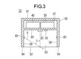
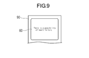
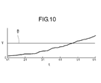
- FIG. 3 is a cross-sectional view taken along the line CC in FIG. 2. It is a top view which shows the state which made the measuring subject contact the cardiac function measuring apparatus. It is sectional drawing which shows the state which made the measuring subject contact the cardiac function measuring apparatus. It is a figure which shows the image data acquired by the imaging part. It is a figure which shows the outer diameter vein specified from the image data acquired by the imaging part. It is a flowchart which shows the flow of control of a cardiac function measuring apparatus. It is a top view which shows the display part on which the warning message was displayed. It is a graph which shows the change every day of the shape complexity computed by the cardiac function measuring device.
- the cardiac function measuring device 10 is a device that can observe the complexity of the shape of the jugular vein in the neck from the body surface.
- the jugular vein swells (hypertrophies) due to the reduced function of the right ventricle and becomes a complex shape.
- a complicated shape means the shape which has dispersion
- the jugular vein includes the external jugular vein and the internal jugular vein.
- the jugular vein observed by the cardiac function measuring device 10 may be the external jugular vein or the internal jugular vein.
- the cardiac function measuring device 10 is used on a daily basis by the measurement subject himself / herself and can monitor changes in the state of the heart over a long period of time. It can also be used for short-term monitoring applications in which the presence or absence of heart failure is determined by a doctor's instruction for a period of about 2 to 3 days, making it possible to make a diagnosis with higher accuracy than observing in a short time at the visit. .
- the cardiac function measuring apparatus 10 stores an image pickup unit 20 that picks up an image, a luminance detection unit 30 that detects luminance, an irradiation unit 80 that emits light, and various data. It has the memory
- the control unit 50 and the storage unit 40 constitute a computer for executing a program. Therefore, the operation of the cardiac function measuring apparatus 10 can be executed by a program.
- the housing 90 has an operation surface 91 on which the display unit 60 and the input unit 70 are arranged, and a measurement surface 92 on which the imaging unit 20, the luminance detection unit 30 and the irradiation unit 80 are arranged.
- the measurement surface 92 of the housing 90 has a recess 93, and the imaging unit 20, the luminance detection unit 30, and the irradiation unit 80 are disposed in the recess 93.
- a support portion 94 that contacts the neck portion during measurement and supports the housing 90 with respect to the neck portion is provided at the edge portion surrounding the recess 93.
- the recess 93 has a bottom surface 95 and a side surface 96 surrounding the bottom surface 95.
- a space 97 in which the storage unit 40 and the control unit 50 are accommodated is provided between the operation surface 91 and the bottom surface 95 of the housing 90.
- the imaging unit 20 is an image sensor that acquires cervical image data in order to observe the bulge of the jugular vein A in the cervical region from the body surface.
- the imaging unit 20 transmits the detected image data to the control unit 50.
- the imaging unit 20 is disposed at the center of the bottom surface 95 of the housing 90 and faces the opening direction of the recess 93.
- the imaging direction in which the imaging unit 20 faces is preferably perpendicular to the measurement surface 92 (the surface on which the support unit 94 exists) so as to be perpendicular to the body surface of the neck contacting the support unit 94.
- the distance from the imaging unit 20 to the measurement surface 92 (distance to the imaging target) is not particularly limited, but is, for example, 5 to 10 mm.
- the distance from the imaging unit 20 to the measurement surface 92 is preferably set based on the viewing angle of the imaging unit 20 and the size of the range to be captured.
- the luminance detection unit 30 is a luminance sensor that detects the luminance of the imaging environment.
- the luminance detection unit 30 transmits the detected luminance data to the control unit 50.
- the luminance detection unit 30 is disposed on the bottom surface 95 adjacent to the luminance detection unit 30.
- the position of the luminance detection unit 30 is not particularly limited as long as the luminance of the imaging environment can be detected.
- the irradiation unit 80 is a light source that emits light, for example, an LED.
- the irradiation unit 80 can be controlled by the control unit 50 to adjust the luminance.
- the irradiating unit 80 irradiates inclined light onto the imaging target on the extended surface of the measurement surface 92 and in front of the imaging unit 20.
- the irradiation unit 80 generates a shadow S (see FIG. 6) on the back side in the irradiation direction X with respect to the protruding part of the body surface. For this reason, the irradiation part 80 makes it easy to detect the jugular vein A by the imaging part 20.
- the irradiation direction X of the irradiation unit 80 is preferably substantially orthogonal to the jugular vein A as a measurement target so as to cause a shadow along the longitudinal direction of the jugular vein A.
- the angle ⁇ of the irradiation direction X with respect to the imaging direction (the direction in which the irradiation unit 80 is directed) is more than 0 degree and less than 90 degrees, preferably 0 to less than 90 degrees so that a shadow is formed on the protruding part of the body surface. It is 83 degrees, and more preferably 78 to 83 degrees.
- one irradiation unit 80 is disposed on each of the side surfaces 96 on both sides of the imaging unit 20.
- the angle ⁇ of each irradiation unit 80 may be the same or different.
- the number of the irradiation parts 80 is not limited, One may be sufficient and three or more may be sufficient.
- the storage unit 40 stores various operation programs such as a measurement program executed by the control unit 50 and various parameters (threshold value, etc.).
- the storage unit 40 further stores data detected by the imaging unit 20 and the luminance detection unit 30 and data calculated by the control unit 50.
- the control unit 50 includes a luminance adjustment unit 51, a vein determination unit 52, an irradiation switching unit 53, and a warning determination unit 54.
- the control unit 50 includes a CPU (Central Processing Unit) and an operation program.
- the control unit 50 includes an imaging unit 20, a luminance detection unit 30, a storage unit 40, a luminance adjustment unit 51, a vein determination unit 52, an irradiation switching unit 53, a warning determination unit 54, an input unit 70, an irradiation unit 80, and a display unit 60. Control the overall operation.
- the luminance adjusting unit 51 acquires luminance data from the luminance detecting unit 30.
- the luminance adjusting unit 51 also uses the acquired luminance data to calculate the condition (output) of the irradiation unit 80 where the luminance becomes a preset target value.
- the luminance adjustment unit 51 controls the irradiation unit 80 under the calculated conditions, and sets the luminance to a target value.
- the vein discriminating unit 52 acquires image data from the imaging unit 20.
- the vein discriminating unit 52 calculates a shape complexity V that is an index indicating the complexity of the shape of the jugular vein A from the image data by a preset method.
- the vein discrimination unit 52 classifies the gradation of each pixel from the acquired image data. For example, each of the three colors of red, green, and blue has 256 gradations.
- the vein discriminating unit 52 monochromeizes the image and further performs a posterization process.
- the vein discriminating unit 52 reads a preset threshold value in the storage unit 40 and performs a posterization process on two gradations to binarize into black and white. As a result, as shown in FIGS.
- a black shadow S appears in a predetermined range on the far side in the irradiation direction X with respect to the protrusion E protruding from the body surface due to the bulge of the jugular vein A.
- the vein determination unit 52 calculates a center line G passing through the center of the shadow S as shown in FIG.
- the vein determination unit 52 specifies the pixels P1 and P2 that are farthest from the specified shadow S.
- the vein discriminating unit 52 specifies an orthogonal line L2 that is orthogonal to the line L1 connecting the pixel P1 and the pixel P2.
- the vein determination unit 52 identifies the orthogonal lines L2 and the edge portions S1 and S2 extending from the pixel P1 to the pixel P2 along the edge of the shadow portion S. Subsequently, the vein discriminating unit 52 specifies the intersections P3 and P4 between the orthogonal line L2 and the edges S1 and S2. The vein discriminating unit 52 specifies an intermediate point P5 located between the intersection point P3 and the intersection point P4. The vein determination unit 52 moves the orthogonal line L2 between the pixel P1 and the pixel P2, and specifies and arranges the intermediate point P5 of each orthogonal line L2. Thereby, the vein discrimination
- the vein discriminating unit 52 calculates a regression curve of the center line G.
- the center line G is a smooth curve from which minute fluctuation components are removed.
- the vein discriminating unit 52 calculates the number of inflection points D of the regression curve.
- the vein discriminating unit 52 sets the inflection point D to a point at which the twice differential value of the regression curve becomes zero (a point at which the slope of the curve becomes zero), and sets the number of the inflection points D to the shape complexity V.
- the larger the shape complexity V the more complicated the shape of the jugular vein A.
- the vein discriminating unit 52 determines the number of inflection points D indicating the complexity of the meandering and the complexity of the shape of the outer diameter vein A.
- the shape complexity V can be set as V.
- the method for calculating the shape complexity V is not particularly limited as long as the shape complexity of the outer diameter vein A can be expressed.
- the shape complexity V may be the number of times the line L1 connecting the farthest pixel P1 and the pixel P2 intersects the center line G.
- the method for calculating the shape complexity V is obtained by dividing the length along the center line G between the farthest pixels P1 and P2 by the linear distance between the pixels P1 and P2 into the shape complexity.
- the degree V may be set.
- the shape complexity V is calculated using the shadow portion S in the method for calculating the shape complexity V.
- the shape complexity V may be calculated using a strong white range appearing on the near side.
- the shape complexity V can be calculated in the same manner as the method of calculating the white range by binarizing the image data and calculating from the shadow portion S described above.
- the method of calculating the shape complexity V specifies the shape of the outer diameter vein A from the shapes in the range where the colors of the acquired image data are different. You can also.
- the shape complexity V may be a change in the width W that is the distance between the intersection P3 and the intersection P4 between the orthogonal line L2 and the edges S1 and S2.
- the vein discriminating unit 52 calculates the width W at each point of a predetermined interval from the pixel P1 to the pixel P2.
- the vein discriminating unit 52 can set, for example, the degree of complexity of the plurality of widths W, the maximum value of the width W, the difference between the maximum value and the average value of the width W, and the like as the shape complexity V.
- the average value of the plurality of shape complexity V calculated using the plurality of irradiation units 80 can be set as the shape complexity V.
- the average value of the shape complexity V it becomes possible to identify the shape complexity with high accuracy. It is also possible to calculate a plurality of shape complexity V from a plurality of irradiation units 80 and select and use only the most favorable value instead of the average value.
- the irradiation switching unit 53 can select and switch the irradiation unit 80 that emits light from the two irradiation units 80.
- the irradiation switching unit 53 transmits a signal to one preset irradiation unit 80 to emit light.
- the irradiation switching unit 53 stops the light irradiation.
- the irradiation switching unit 53 causes the other irradiation units 80 to emit light after the irradiation by one irradiation unit 80 is completed.
- the irradiation switching unit 53 stops the irradiation after the irradiation by all the irradiation units 80 is completed.
- the warning determination unit 54 compares the shape complexity V with a threshold value.
- the threshold value is preset in the storage unit 40, input from the input unit 70, or calculated from past data.
- the warning determination unit 54 determines that the cardiac function is abnormal when the shape complexity V exceeds the threshold value.
- the warning determination part 54 determines with a cardiac function being normal, when the shape complexity V is below a threshold value.
- the warning determination unit 54 causes the display unit 60 to display the determination result.
- the threshold value of the warning determination unit 54 may be, for example, an upper limit value of an average value of a general person, or a value obtained by multiplying an average value for the past several months of a measurement target person by a coefficient. There may be.
- the input unit 70 is a part where the measurement subject performs an input operation.
- the input unit 70 includes, for example, a switch and a button.
- the input unit may be a touch panel, a keyboard, a mouse, or the like.
- the input unit 70 is used for inputting and resetting various parameters such as threshold values, starting and ending measurement, selecting measurement results and calculation results to be displayed, selecting graphs and tables to be displayed, and the like.
- the display unit 60 is a display device such as an LCD (Liquid Crystal Display) or an organic EL (Electro-Luminescence) display.
- the display unit 60 may be a touch panel that also serves as the input unit 70.
- the display unit 60 can display values, measurement results, calculation results, determination results, and the like input to the input unit 70 as characters, numerical values, tables, graphs, or the like.
- the measurement subject brings the support portion 94 of the measurement surface 92 of the cardiac function measuring device 10 into contact with the body surface near the jugular vein A.
- the jugular vein A is positioned in front of the imaging unit 20.
- the irradiation direction X of the irradiation part 80 is set to a direction orthogonal to the jugular vein A as much as possible.
- the position of the body surface with which the cardiac function measuring device 10 is brought into contact is the same position every time.
- the measurement subject operates the input unit 70 of the housing 90 to start measurement.
- the irradiation switching part 53 transmits an instruction
- the luminance adjusting unit 51 receives luminance data from the luminance detecting unit 30 (step 2).
- the luminance adjustment unit 51 calculates the condition (output) of the irradiation unit 80 from which the luminance becomes a preset target value from the received luminance data. Subsequently, the luminance adjustment unit 51 sends a signal to the irradiation unit 80 so as to satisfy the calculated condition, and sets the luminance to a target value (step 3). Thereby, the brightness of the imaging environment can be kept constant.
- the vein discriminating unit 52 receives image data from the imaging unit 20 (step 4). Next, the vein discriminating unit 52 identifies the shadow S of the protruding portion E of the body surface protruding by the jugular vein A as shown in FIG. 6 (step 5). Subsequently, the vein discriminating unit 52 calculates the shape complexity V from the information of the identified shadow part S (step 6).
- the vein discriminating unit 52 transmits information to that effect to the irradiation switching unit 53.
- the irradiation switching unit 53 that has received the information determines whether or not the irradiation unit 80 being irradiated is the last irradiation unit 80 (step 7).
- the irradiation switching unit 53 transmits an instruction to the irradiation unit 80 being irradiated to stop the light irradiation and transmits an instruction to the other irradiation units 80. (Step 8).
- Step 1 to Step 6 described above are repeated, and the second shape complexity V is calculated using the second irradiation unit 80.
- the vein discriminating unit 52 transmits information to that effect to the irradiation switching unit 53.
- the irradiation switching unit 53 that has received the information determines whether or not the irradiation unit 80 being irradiated is the last irradiation unit 80 (step 7).
- the irradiation switching unit 53 transmits an instruction to the irradiation unit 80 being irradiated to stop the light irradiation.
- the vein determination unit 52 calculates the average value of the shape complexity V calculated by each of the plurality of irradiation units 80 (step 9).
- the warning determination unit 54 compares the average value of the shape complexity V with a threshold value. Thereby, the warning determination part 54 determines whether the average value of the shape complexity V is normal (step 10). When the warning determination unit 54 determines that the average value of the shape complexity V is abnormal, the warning determination unit 54 displays a warning message on the display unit 60 as shown in FIG. 9 (step 11). The content of the warning message can be set as appropriate.
- the control unit 50 can cause the display unit 60 to display the change of the average value of the shape complexity V for each measurement together with the past data, with the horizontal axis as time t.
- the control unit 50 can display the upper limit B (threshold value) of the normal value of the shape complexity V with a line on the graph displayed on the display unit 60.
- the shape complexity V exceeds the upper limit B, it can be determined that the running path of the jugular vein A has been bent by the blood pressure, and that there is a possibility of heart failure or heart failure. Therefore, the measurement subject himself / herself can easily monitor the degree of progression of heart failure (decrease in cardiac function) over a long period of time.
- control unit 50 stores data such as the calculated shape complexity V and presence / absence of abnormality in the storage unit 40 (step 12). Thereby, the measurement for one time by the cardiac function measuring apparatus 10 is completed.
- the measurement by the cardiac function measuring device 10 is performed, for example, every day. Thereby, the cardiac function can be monitored over a long period. Note that the measurement may not be performed every day.
- the cardiac function measurement device 10 is a device for measuring data for evaluating cardiac function, and includes an irradiation unit 80 for irradiating light to the neck, and the neck.
- An image capturing unit 20 for acquiring image data of a portion, and a vein determining unit 52 for determining the shape of the jugular vein A in the acquired image data and calculating a shape complexity V representing the complexity of the shape.
- the cardiac function measuring apparatus 10 configured as described above can calculate the shape complexity V representing the complexity of the shape of the jugular vein A using the image data of the neck generated by the light irradiated from the irradiation unit 80. This makes it possible to monitor the complexity of the shape of the jugular vein A, which serves as an indicator of a decrease in cardiac function, by the shape complexity V, and it becomes easy to monitor the cardiac function. Moreover, since the cardiac function measuring apparatus 10 can be configured in a compact manner and is easy to measure, the burden on the measurement subject is small and long-term monitoring is possible.
- the cardiac function measuring apparatus 10 further includes a storage unit 40 capable of storing the shape complexity V, and can compare the shape complexity V measured and calculated at different times. Thereby, since the temporal change of the cardiac function can be observed, the cardiac function can be monitored for a long time and easily.
- the vein discriminating unit 52 calculates a center line G (line) along the determined shape of the jugular vein A, calculates a regression curve of the center line G, and calculates the number of inflection points D of the regression curve.
- the complexity can be V.
- the shape complexity V which is an index of a decrease in cardiac function, can be calculated easily and accurately from the shape of the jugular vein A.
- the line along the shape of the jugular vein A is not limited to the center line G as long as the line represents the characteristics of the jugular vein A. For example, the line along the edge of the identified jugular vein A (edges S1, S2). ).
- the cardiac function measuring apparatus 10 further includes a warning determination unit 54 that compares the calculated shape complexity V with a threshold value and determines whether or not to issue a warning. Thereby, since determination of a cardiac function is performed automatically, determination of the fall of a cardiac function becomes easy.
- the cardiac function measuring apparatus 10 further includes a luminance detection unit 30 that detects luminance, and a luminance adjustment unit 51 that adjusts the irradiation unit 80 so that the luminance detected by the luminance detection unit 30 approaches a target value. .
- the cardiac function measuring apparatus 10 further includes a support portion 94 that is positioned on the imaging direction side of the imaging unit 20 and can contact the neck. Thereby, the distance from the imaging part 20 to a neck can be appropriately set for every measurement by making the support part 94 contact a neck. For this reason, the imaging conditions for each measurement are equal, and the cardiac function can be monitored with higher accuracy.
- the present invention also includes a cardiac function measurement method for measuring data for evaluating cardiac function.
- the cardiac function measurement method includes a step of irradiating light to a neck, a step of acquiring image data of the neck irradiated with light, a step of determining a shape of the jugular vein A in the acquired image data, and a determination Calculating a shape complexity V representing the complexity of the shape of the jugular vein A.
- the cardiac function measuring method configured as described above can calculate the shape complexity V representing the complexity of the shape of the jugular vein A using the image data of the neck generated by the light irradiated from the irradiation unit 80. This makes it possible to monitor the complexity of the shape of the jugular vein A, which serves as an indicator of a decrease in cardiac function, by the shape complexity V, and it becomes easy to monitor the cardiac function. In addition, since measurement is easy, the burden on the measurement subject is small, and long-term monitoring is possible.
- the cardiac function measuring method further includes a step of comparing the shape complexity V measured and calculated at different times. Thereby, since the temporal change of the cardiac function can be observed, the cardiac function can be monitored for a long time and easily.
- a center line G (line) along the determined shape of the jugular vein A is calculated, a regression curve of the center line G is calculated, and the regression is performed.
- the number of inflection points D of the curve can be made the shape complexity V.
- the shape complexity V which is an index of decrease in cardiac function, can be easily calculated from the shape of the jugular vein A with high accuracy.
- the cardiac function measuring method further includes a step of comparing the calculated shape complexity V with a threshold value and determining whether or not to issue a warning.
- the present invention also includes a cardiac function measurement program executed by a computer to measure data for evaluating cardiac function.
- the cardiac function measurement program includes a step of acquiring cervical image data from the imaging unit 20 capable of imaging the cervix, a step of determining the shape of the jugular vein A in the acquired image data, and the determined jugular vein A Calculating a shape complexity V representing the complexity of the shape.
- the cardiac function measurement program configured as described above can calculate the shape complexity V representing the complexity of the shape of the jugular vein A using the image data of the neck generated by the light irradiated from the irradiation unit 80.
- the complexity of the shape of the jugular vein A which is an index of the decrease in cardiac function, can be observed by the shape complexity V, and monitoring of the cardiac function is facilitated.
- the burden on the measurement subject is small, and long-term monitoring is possible.
- the cardiac function measurement program further includes a step of reading out the shape complexity V measured and calculated at different times from the storage unit, and a step of comparing a plurality of shape complexity V measured at different times. .
- the cardiac function measurement program calculates a center line G (line) along the determined shape of the jugular vein A in the step of calculating the shape complexity V, calculates a regression curve of the center line G, and calculates the regression.
- the number of inflection points D of the curve can be made the shape complexity V.
- the shape complexity V which is an index of decrease in cardiac function, can be easily calculated from the shape of the jugular vein A with high accuracy.
- the cardiac function measurement program further includes a step of comparing the calculated shape complexity V with a preset threshold value and determining whether or not to issue a warning.
- the configuration of the housing is not particularly limited. Even if at least a part of functions of the cardiac function measuring device is configured by a portable terminal such as a smartphone or a tablet terminal and an application (program), or a server computer terminal connected to the Internet and an application (program), Good. In this case, some functions may be wirelessly connected to the portable terminal using a communication technology such as NFC (Near Field Communication) or Wifi (registered trademark).
- a communication technology such as NFC (Near Field Communication) or Wifi (registered trademark).
- the cardiac function measuring device 10 is a device that is assumed to be used by the measurement target person, a medical worker such as a doctor or a nurse may use it for the measurement target person.
- the external jugular vein is easy to observe from the body surface, but the internal jugular vein is located deep in the body, so that it may not be observed on the body surface by a general image sensor (imaging device). For this reason, when observing the internal jugular vein, it is preferable that the imaging unit can observe the deep part of the body.
- the imaging unit that can observe the deep part of the body is, for example, an ultrasonic probe using an ultrasonic echo, an optical coherence tomography diagnosis device (OCT: Optical Coherence Tomography), or an optical frequency domain imaging method (OFDI: Optical Frequency Domain Imaging). Etc. is a device using the above.
- the imaging unit that can observe the deep part of the body measures the sound of the pulsation of the jugular vein at a plurality of locations on the body surface, and identifies the shape of the jugular vein from the intensity of the pulsation sound at each measurement location It may be.
- a cardiac function measuring device, a cardiac function measuring method, and a cardiac function measuring program can be configured using an imaging unit capable of observing the deep part of the body as described above.
- 10 cardiac function measuring device 20 imaging unit, 30 luminance detector, 40 storage unit, 50 control unit, 51 brightness control unit, 52 Vein discrimination unit, 53 Irradiation switching part, 54 Warning determination unit, 80 Irradiation part, 94 support part, A jugular vein, B Upper limit (threshold), D inflection point, G center line (line), X irradiation direction, V Shape complexity.
Landscapes
- Health & Medical Sciences (AREA)
- Life Sciences & Earth Sciences (AREA)
- Engineering & Computer Science (AREA)
- Physics & Mathematics (AREA)
- General Health & Medical Sciences (AREA)
- Biomedical Technology (AREA)
- Heart & Thoracic Surgery (AREA)
- Medical Informatics (AREA)
- Molecular Biology (AREA)
- Surgery (AREA)
- Animal Behavior & Ethology (AREA)
- Biophysics (AREA)
- Public Health (AREA)
- Veterinary Medicine (AREA)
- Pathology (AREA)
- Physiology (AREA)
- Geometry (AREA)
- General Physics & Mathematics (AREA)
- Theoretical Computer Science (AREA)
- Dentistry (AREA)
- Oral & Maxillofacial Surgery (AREA)
- Vascular Medicine (AREA)
- Cardiology (AREA)
- Computer Vision & Pattern Recognition (AREA)
- Measurement Of The Respiration, Hearing Ability, Form, And Blood Characteristics Of Living Organisms (AREA)
- Measuring Pulse, Heart Rate, Blood Pressure Or Blood Flow (AREA)
Abstract
心機能を長期的に監視でき、かつ測定対象者への負担が小さい心機能測定装置、心機能測定方法および心機能測定プログラムを提供する。 心機能を評価するためのデータを測定するための心機能測定装置(10)であって、頸部へ光を照射するための照射部(80)と、頸部の画像データを取得するための撮像部(20)と、取得した画像データ内の頸静脈(A)の形状を判別し、当該形状の複雑さを表す形状複雑度(V)を算出する静脈判別部(52)と、を有する。
Description
本発明は、心機能を評価するためのデータを測定する心機能測定装置、心機能測定方法および心機能測定プログラムに関する。
心臓の働きが不十分で拍出量の低下が起こると、心臓拍出量を維持する生体の仕組みが働き、拍出量の低下が抑えられる。しかしながら、体のさまざまな部分に負担がかかるため、結果として症状が出現する。心不全とは、病名ではなく、このような「心臓の働きが不十分な結果として生じた体の状態」を示す。
心不全になると、心臓のポンプ機能が低下して十分に血液を送り出せなくなる。このため、心臓から送り出せなくなった血液が、循環系において心臓の直前の臓器に溜まり、症状が現れる。左心不全の場合には、肺循環系に症状が現れ、右心不全の場合には、体循環系に症状が現れる。全身から戻る血液は右心へ流れるが、右心不全ではそれが滞るために体循環系にうっ血が起こる。この結果として、頸静脈の怒張、肝腫大、腹水、浮腫などの症状が現れる。
このため、心不全を検出する様々な装置が提案されている。例えば特許文献1には、鼻に挿入するカニューレや口に装着するマスクにより呼吸を監視することで、心不全を検出する装置が記載されている。
心不全の兆候を自覚することは、困難である。このため、心筋梗塞などの急性増悪が起こることで、初めて気付くことが多い。しかしながら、早期に発見する方が、当然に対処が容易となるため、測定対象者への負担が小さく、かつ長期的に監視できることが望まれる。
しかしながら、特許文献1に記載の装置は、大型であるため、日常的に装着して測定することが困難であり、測定対象者への負担が大きい。
本発明は、上述した課題を解決するためになされたものであり、心臓を長期的に監視でき、かつ測定対象者への負担が小さい心機能測定装置、心機能測定方法および心機能測定プログラムを提供することを目的とする。
上記目的を達成する心機能測定装置は、心機能を評価するためのデータを測定するための心機能測定装置であって、頸部へ光を照射するための照射部と、頸部の画像データを取得するための撮像部と、取得した前記画像データ内の頸静脈の形状を判別し、当該形状の複雑さを表す形状複雑度を算出する静脈判別部と、を有する。
上記目的を達成する心機能測定方法は、心機能を評価するためのデータを測定するための心機能測定方法であって、光を頸部へ照射するステップと、光を照射された頸部の画像データを取得するステップと、取得した画像データ内の頸静脈の形状を判別するステップと、判別された頸静脈の形状の複雑さを表す形状複雑度を算出するステップと、を有する。
上記目的を達成する心機能測定プログラムは、心機能を評価するためのデータを測定するためにコンピュータによって実行される心機能測定プログラムであって、頸部を撮像可能な撮像部から頸部の画像データを取得するステップと、取得した画像データ内の頸静脈の形状を判別するステップと、判別された頸静脈の形状の複雑さを表す形状複雑度を算出するステップと、を有する。
上記のように構成された心機能測定装置、心機能測定方法および心機能測定プログラムは、頸部の画像データを利用して、心機能の低下の指標となる頸静脈の形状の複雑さを、形状複雑度により監察できる。当該心機能測定装置は、コンパクトに構成可能であり、かつ測定が容易であるため、測定対象者への負担が小さく、長期的な監視が可能である。
以下、図面を参照して、本発明の実施の形態を説明する。なお、図面の寸法比率は、説明の都合上、誇張されて実際の比率とは異なる場合がある。
本発明の実施形態に係る心機能測定装置10は、頸部における頸静脈の形状の複雑度を体表から観察できる装置である。頸静脈は、右心室の機能が低下することで膨らみ(肥大し)、複雑な形状となる。なお、複雑な形状とは、各部位の寸法、大きさ、角度等が一定せずに、ばらつきがある形状を意味する。このため、頸静脈の複雑さを観察することは、右心機能の低下(右心不全)を判定可能とする。頸静脈は、外頸静脈および内頸静脈を含んでいる。したがって、心機能測定装置10により観察する頸静脈は、外頸静脈であっても、内頸静脈であってもよい。心機能測定装置10は、測定対象者自身によって日常的に使用され、心臓の状態の変化を長期的に監視することができる。また、医師の指示により2~3日程度の期間心不全の有無を判定することで、来院時に短時間で観察するよりも精度の高い診断ができる、という短期的な監視用途にも用いることができる。
心機能測定装置10は、図1~4に示すように、画像を撮像する撮像部20と、輝度を検出する輝度検出部30と、光を照射する照射部80と、各種データが格納される記憶部40と、制御部50と、入力部70と、表示部60と、これらを収容する筐体90とを有している。制御部50および記憶部40は、プログラムを実行するためのコンピュータを構成する。したがって、心機能測定装置10の動作は、プログラムにより実行することができる。
筐体90は、表示部60および入力部70が配置される操作面91と、撮像部20、輝度検出部30および照射部80が配置される測定面92を有している。筐体90の測定面92は、凹部93を有し、この凹部93に、撮像部20、輝度検出部30および照射部80が配置されている。凹部93を囲む縁部には、測定時に頸部に接触し、筐体90を頸部に対して支持する支持部94が設けられる。凹部93は、底面95と、底面95を囲む側面96を有している。筐体90の操作面91と底面95の間には、記憶部40および制御部50が収容される空間97が設けられている。
撮像部20は、頸部における頸静脈Aの膨らみを体表から観察するために、頸部の画像データを取得する画像センサである。撮像部20は、検出した画像データを、制御部50へ送信する。撮像部20は、筐体90の底面95の中央部に配置され、凹部93の開口方向を向いている。撮像部20が向く撮像方向は、支持部94に接触した頸部の体表と垂直となるように、測定面92(支持部94が存在する面)と垂直であることが好ましい。撮像部20から測定面92までの距離(撮像対象までの距離)は、特に限定されないが、例えば5~10mmである。撮像部20から測定面92までの距離は、撮像部20の視野角と、撮像したい範囲の大きさから設定されることが好ましい。
輝度検出部30は、撮像環境の輝度を検出する輝度センサである。輝度検出部30は、検出した輝度データを、制御部50へ送信する。輝度検出部30は、輝度検出部30に隣接して底面95に配置される。なお、輝度検出部30の位置は、撮像環境の輝度を検出できれば、特に限定されない。
照射部80は、光を照射する光源であり、例えばLEDである。照射部80は、制御部50により制御されて輝度を調節可能である。照射部80は、測定面92の延長面上であって撮像部20の正面の撮像対象に対して、傾斜する光を照射する。照射部80は、体表の突出している部位に対して照射方向Xの奥側に、影部S(図6を参照)を生じさせる。このため、照射部80は、撮像部20により頸静脈Aを検出することを容易とする。照射部80の照射方向Xは、頸静脈Aの長尺方向に沿って影を生じさせるように、測定対象である頸静脈Aと略直交することが好ましい。撮像方向(照射部80が向いている方向)に対する照射方向Xの角度θは、体表の突出している部位に影ができるように、0度を超えて90度未満であり、好ましくは0~83度であり、より好ましくは78~83度である。
照射部80は、本実施形態では、撮像部20を挟んで両側の側面96に1個ずつ配置される。各々の照射部80の角度θは、同じであっても異なってもよい。なお、照射部80の数は限定されず、1個のみであってもよく、3個以上であってもよい。
記憶部40は、制御部50にて実行される測定プログラムなどの各種動作プログラムや、各種パラメータ(閾値など)を格納する。記憶部40は、さらに、撮像部20および輝度検出部30で検出されたデータと、制御部50にて算出されたデータを格納する。
制御部50は、輝度調節部51と、静脈判別部52と、照射切替部53と、警告判定部54とを有している。制御部50は、CPU(Central Processing Unit)および動作プログラムにより構成される。制御部50は、撮像部20、輝度検出部30、記憶部40、輝度調節部51、静脈判別部52、照射切替部53、警告判定部54、入力部70、照射部80および表示部60の動作を統括的に制御する。
輝度調節部51は、輝度検出部30から輝度データを取得する。輝度調節部51は、取得した輝度データも用いて、輝度が、予め設定された目標値となる照射部80の条件(出力)を算出する。次に、輝度調節部51は、算出した条件で照射部80を制御し、輝度を目標値に設定する。
静脈判別部52は、撮像部20から画像データを取得する。静脈判別部52は、画像データから、予め設定された方法により、頸静脈Aの形状の複雑さを示す指標となる形状複雑度Vを算出する。
画像データから形状複雑度Vを算出する例を説明する。静脈判別部52は、取得した画像データから、各ピクセルの階調を区分する。階調は、例えば、赤、緑、青の3色の各々を256階調とする。次に、静脈判別部52は、画像をモノクロ化し、さらに、ポスタリゼーション処理を施す。ポスタリゼーション処置において、静脈判別部52は、記憶部40に予め設定された閾値を読み込み、2階調にポスタリゼーション処理して白黒に2値化する。これにより、図5、6に示すように、頸静脈Aの膨らみにより体表の突出した突出部Eに対して照射方向Xの奥側に、黒色の影部Sが所定の範囲で表れる。次に、静脈判別部52は、図7に示すように、影部Sの中央を通る中央線Gを算出する。中央線Gを特定する方法の例として、例えば、静脈判別部52は、特定した影部Sの最も離れたピクセルP1、P2を特定する。次に、静脈判別部52は、ピクセルP1とピクセルP2を結ぶ線L1と直交する直交線L2を特定する。次に、静脈判別部52は、直交線L2と、影部Sの縁に沿ってピクセルP1からピクセルP2まで伸びる縁部S1、S2を特定する。続いて、静脈判別部52は、直交線L2と縁部S1、S2の交点P3、P4を特定する。静脈判別部52は、交点P3と交点P4の中間に位置する中間点P5を特定する。静脈判別部52は、直交線L2をピクセルP1とピクセルP2の間で移動させ、各直交線L2の中間点P5を特定して並べる。これにより、静脈判別部52は、中間点P5を並べた中央線Gを特定できる。なお、中央線Gの算出方法は、上記の方法に限定されない。
次に、静脈判別部52は、中央線Gの回帰曲線を算出する。これにより、中央線Gは、微小な変動成分が除去され、滑らかな曲線となる。次に、静脈判別部52は、回帰曲線の変曲点Dの数を算出する。静脈判別部52は、回帰曲線の2回微分値がゼロとなる点(曲線の傾きがゼロとなる点)を変曲点Dとし、この変曲点Dの数を形状複雑度Vとする。形状複雑度Vが大きいほど、頸静脈Aの形状が複雑である。すなわち、心機能の低下により膨らむ外径静脈Aは、複雑に蛇行しやすいため、静脈判別部52は、蛇行の複雑さを示す変曲点の数Dを、外径静脈Aの形状の複雑さを表す形状複雑度Vとすることができる。
なお、形状複雑度Vを算出する方法は、外径静脈Aの形状の複雑さを表すことができれば、特に制限されない。例えば、形状複雑度Vを算出する方法は、最も離れたピクセルP1とピクセルP2を結ぶ線L1と中央線Gが交差する回数を、形状複雑度Vとしてもよい。また、形状複雑度Vを算出する方法は、最も離れたピクセルP1とピクセルP2の間の中央線Gに沿う長さを、ピクセルP1とピクセルP2の間の直線距離で割った値を、形状複雑度Vとしてもよい。また、上述した例では、形状複雑度Vを算出する方法は、影部Sを利用して形状複雑度Vを算出したが、頸静脈Aの膨らみにより突出した突出部Eに対して照射方向Xの手前側に現れる白色の強い範囲を用いて、形状複雑度Vを算出してもよい。形状複雑度Vを算出する方法は、画像データを2値化して白色の範囲を特定し、前述の影部Sから算出する方法と同様に、形状複雑度Vを算出することができる。また、外径静脈Aは、体表において周囲と色が異なるため、形状複雑度Vを算出する方法は、取得した画像データの色が異なる範囲の形状から、外径静脈Aの形状を特定することもできる。
また、形状複雑度Vを算出する方法は、直交線L2と縁部S1、S2の交点P3および交点P4の距離である幅Wの変動を、形状複雑度Vとしてもよい。この場合、静脈判別部52は、ピクセルP1からピクセルP2までの所定間隔の各点で幅Wを算出する。静脈判別部52は、例えば、複数の幅Wの散布度や、幅Wの最大値や、幅Wの最大値と平均値の差などを、形状複雑度Vとすることができる。
また、複数の照射部80を利用して算出した複数の形状複雑度Vの平均値を、形状複雑度Vとすることができる。形状複雑度Vの平均値を用いることで、形状の複雑さを高精度に識別することが可能となる。また、複数の照射部80から複数の形状複雑度Vを算出し、平均値ではなく、最も条件のよい値のみを選択して利用することもできる。
照射切替部53は、2つの照射部80から、光を照射する照射部80を選択して切り替えることができる。照射切替部53は、計測が開始されると、予め設定された1つの照射部80に信号を送信し、光を照射させる。照射切替部53は、静脈判別部52から、形状複雑度Vの算出が終了したことを示す情報を受け取ると、光の照射を停止させる。照射切替部53は、1つの照射部80による照射が終了した後、他の照射部80に光を照射させる。照射切替部53は、全ての照射部80による照射が完了した後、照射を停止させる。
警告判定部54は、形状複雑度Vを、閾値と比較する。閾値は、予め記憶部40に設定されているか、入力部70から入力されるか、または、過去のデータから算出される。警告判定部54は、形状複雑度Vが閾値を超える場合、心機能に異常があると判定する。また、警告判定部54は、形状複雑度Vが閾値以下である場合、心機能が正常であると判定する。警告判定部54は、心機能に異常があると判定した場合、表示部60に判定結果を表示させる。なお警告判定部54の閾値は、例えば、一般の人の平均的な値の上限値であってもよく、または、測定対象者の過去の数か月分の平均値に係数を乗じた値であってもよい。
入力部70は、測定対象者が入力操作を行う部位である。入力部70は、例えば、スイッチ、ボタン等を有している。また、入力部は、タッチパネル、キーボード、マウス等であってもよい。入力部70は、閾値などの各種パラメータの入力や再設定、測定の開始や終了、表示する計測結果や算出結果の選択、表示するグラフや表の選択等に使用される。
表示部60は、例えばLCD(Liquid Crystal Display)や有機EL(Electro-Luminescence)ディスプレイ等のディスプレイデバイスである。表示部60は、入力部70を兼ねたタッチパネルであってもよい。表示部60は、入力部70に入力した値、計測結果、算出結果、判定結果等を、文字、数値、表またはグラフ等で表示できる。
次に、本実施形態に係る心機能測定装置10を用いた測定方法を、図8に示すフローチャートを参照しつつ説明する。
まず、測定対象者は、図4、5に示すように、頸静脈Aの近くの体表に、心機能測定装置10の測定面92の支持部94を接触させる。このとき、撮像部20の正面に、頸静脈Aを位置させる。また、影部Sを良好に生じさせるために、照射部80の照射方向Xを、できるだけ頸静脈Aと直交する方向とする。心機能測定装置10を接触させる体表の位置は、毎回同じ位置とする。
次に、測定対象者は、筐体90の入力部70を操作し、計測を開始させる。これにより、照射切替部53が、予め設定された1つ目の照射部80へ指示を送信し、照射部80から光を照射させる(ステップ1)。
次に、輝度調節部51が、輝度検出部30から輝度データを受け取る(ステップ2)。輝度調節部51は、受け取った輝度データから、輝度が予め設定された目標値となる照射部80の条件(出力)を算出する。続いて、輝度調節部51は、算出した条件となるように照射部80へ信号を送り、輝度を目標値に設定する(ステップ3)。これにより、撮像環境の輝度を一定に保つことができる。
次に、静脈判別部52が、撮像部20から画像データを受信する(ステップ4)。次に、静脈判別部52は、図6に示すように、頸静脈Aにより突出した体表の突出部Eの影部Sを特定する(ステップ5)。続いて、静脈判別部52は、特定した影部Sの情報から、形状複雑度Vを算出する(ステップ6)。
静脈判別部52における形状複雑度Vの算出が完了した後、静脈判別部52は、照射切替部53へその旨の情報を送信する。情報を受け取った照射切替部53は、照射中の照射部80が最後の照射部80か否かを判別する(ステップ7)。照射中の照射部80が最後の照射部80でない場合、照射切替部53は、照射中の照射部80へ指示を送信して光の照射を停止させ、他の照射部80へ指示を送信して光を照射させる(ステップ8)。
続いて、上述したステップ1~ステップ6を繰り返し、2つ目の照射部80を用いて、2つ目の形状複雑度Vを算出する。
静脈判別部52における2つ目の形状複雑度Vの算出が完了した後、静脈判別部52は、照射切替部53へその旨の情報を送信する。情報を受け取った照射切替部53は、照射中の照射部80が最後の照射部80か否かを判別する(ステップ7)。照射中の照射部80が最後の照射部80である場合、照射切替部53は、照射中の照射部80へ指示を送信して光の照射を停止させる。この後、静脈判別部52は、複数の照射部80の各々で算出された形状複雑度Vの平均値を算出する(ステップ9)。
次に、警告判定部54が、形状複雑度Vの平均値を、閾値と比較する。これにより、警告判定部54は、形状複雑度Vの平均値が正常か否かを判定する(ステップ10)。警告判定部54は、形状複雑度Vの平均値を異常と判定した場合、図9に示すように、表示部60に、警告メッセージを表示させる(ステップ11)。なお、警告メッセージの内容は、適宜設定できる。
また、制御部50は、図10に示すように、形状複雑度Vの平均値の計測毎の変化を、過去のデータとともに、横軸を時間tとして表示部60に表示させることができる。制御部50は、表示部60に表示させるグラフに、形状複雑度Vの正常値の上限B(閾値)を、線で表示できる。このグラフにおいて、形状複雑度Vが上限Bを超えると、頸静脈Aの走行経路が血液圧力によって曲げられてしまっており、心不全または心不全の可能性があると判定できる。したがって、心不全の進行(心機能の低下)の程度を、測定対象者自身が、長期にわたって容易に監視できる。
この後、制御部50は、算出した形状複雑度V、異常の有無等のデータを、記憶部40に記憶させる(ステップ12)。これにより、心機能測定装置10による1回分の計測が完了する。心機能測定装置10による測定は、例えば1日毎に行われる。これにより、心機能を長期的に監視できる。なお、測定は、1日毎でなくてもよい。
以上のように、本実施形態に係る心機能測定装置10は、心機能を評価するためのデータを測定するための装置であって、頸部へ光を照射するための照射部80と、頸部の画像データを取得するための撮像部20と、取得した画像データ内の頸静脈Aの形状を判別し、当該形状の複雑さを表す形状複雑度Vを算出する静脈判別部52と、を有する。
上記のように構成した心機能測定装置10は、照射部80から照射する光によって生じる頸部の画像データを利用して、頸静脈Aの形状の複雑さを表す形状複雑度Vを算出できる。これにより、心機能の低下の指標となる頸静脈Aの形状の複雑さを形状複雑度Vにより監察でき、心機能の監視が容易となる。また、心機能測定装置10は、コンパクトに構成可能であり、かつ測定が容易であるため、測定対象者への負担が小さく、長期的な監視が可能である。
また、心機能測定装置10は、形状複雑度Vを記憶可能な記憶部40をさらに有し、異なる時間に測定されて算出された形状複雑度Vを比較可能である。これにより、心機能の時間変化を観察できるため、心機能を長期的かつ容易に監視できる。
また、静脈判別部52は、判別した頸静脈Aの形状に沿う中心線G(線)を算出し、当該中心線Gの回帰曲線を算出し、当該回帰曲線の変曲点Dの数を形状複雑度Vとすることができる。これにより、頸静脈Aの形状から、心機能の低下の指標となる形状複雑度Vを精度よく容易に算出できる。なお、頸静脈Aの形状に沿う線は、頸静脈Aの特徴を表している線であれば中心線Gに限定されず、例えば判別した頸静脈Aの縁に沿う線(縁部S1、S2)であってもよい。
また、心機能測定装置10は、算出された形状複雑度Vを閾値と比較し、警告を出すか否かを判定する警告判定部54をさらに有する。これにより、心機能の判定が自動で行われるため、心機能の低下の判定が容易となる。
また、心機能測定装置10は、輝度を検出する輝度検出部30と、輝度検出部30により検出される輝度を目標値に近づけるように照射部80を調節する輝度調節部51と、をさらに有する。これにより、撮像環境の輝度を測定毎に適切に設定できるため、測定毎の撮像条件が等しくなり、心機能をより高い精度で監視できる。
また、心機能測定装置10は、撮像部20よりも撮像方向側に位置して頸部に接触可能な支持部94をさらに有する。これにより、支持部94を頸部に接触させることで、撮像部20から頸部までの距離を測定毎に適切に設定できる。このため、測定毎の撮像条件が等しくなり、心機能をより高い精度で監視できる。
また、本発明は、心機能を評価するためのデータを測定するための心機能測定方法をも含む。心機能測定方法は、光を頸部へ照射するステップと、光を照射された頸部の画像データを取得するステップと、取得した画像データ内の頸静脈Aの形状を判別するステップと、判別された頸静脈Aの形状の複雑さを表す形状複雑度Vを算出するステップと、を有する。
上記のように構成した心機能測定方法は、照射部80から照射する光によって生じる頸部の画像データを利用して、頸静脈Aの形状の複雑さを表す形状複雑度Vを算出できる。これにより、心機能の低下の指標となる頸静脈Aの形状の複雑さを形状複雑度Vにより監察でき、心機能の監視が容易となる。また、測定が容易であるため、測定対象者への負担が小さく、長期的な監視が可能である。
また、心機能測定方法は、異なる時間に測定されて算出された形状複雑度Vを比較するステップをさらに有する。これにより、心機能の時間変化を観察できるため、心機能を長期的かつ容易に監視できる。
また、心機能測定方法は、形状複雑度Vを算出するステップにおいて、判別した頸静脈Aの形状に沿う中心線G(線)を算出し、当該中心線Gの回帰曲線を算出し、当該回帰曲線の変曲点Dの数を形状複雑度Vとすることができる。これにより、頸静脈Aの形状から、心機能の低下の指標となる形状複雑度Vを精度よく容易に算出できる。
また、心機能測定方法は、算出された形状複雑度Vを閾値と比較し、警告を出すか否かを判定するステップをさらに有する。これにより、心機能の判定が自動で行われるため、心機能の低下の判定が容易となる。
また、本発明は、心機能を評価するためのデータを測定するためにコンピュータによって実行される心機能測定プログラムをも含む。心機能測定プログラムは、頸部を撮像可能な撮像部20から頸部の画像データを取得するステップと、取得した画像データ内の頸静脈Aの形状を判別するステップと、判別された頸静脈Aの形状の複雑さを表す形状複雑度Vを算出するステップと、を有する。
上記のように構成した心機能測定プログラムは、照射部80から照射する光によって生じる頸部の画像データを利用して、頸静脈Aの形状の複雑さを表す形状複雑度Vを算出できる。これにより、心機能の低下の指標となる頸静脈Aの形状の複雑さを形状複雑度Vにより観察でき、心機能の監視が容易となる。また、測定が容易であるため、測定対象者への負担が小さく、長期的な監視が可能である。
また、心機能測定プログラムは、異なる時間に測定されて算出された形状複雑度Vを記憶部から読み出すステップと、異なる時間に測定された複数の形状複雑度Vを比較するステップと、をさらに有する。これにより、心機能の時間変化を観察できるため、心機能を長期的かつ容易に監視できる。
また、心機能測定プログラムは、形状複雑度Vを算出するステップにおいて、判別した頸静脈Aの形状に沿う中心線G(線)を算出し、当該中心線Gの回帰曲線を算出し、当該回帰曲線の変曲点Dの数を形状複雑度Vとすることができる。これにより、頸静脈Aの形状から、心機能の低下の指標となる形状複雑度Vを精度よく容易に算出できる。
また、心機能測定プログラムは、算出された形状複雑度Vを予め設定された閾値と比較し、警告を出すか否かを判定するステップをさらに有する。これにより、心機能の判定が自動で行われるため、心機能の低下の判定が容易となる。
なお、本発明は、上述した実施形態のみに限定されるものではなく、本発明の技術的思想内において当業者により種々変更が可能である。例えば、筐体の構成は、特に限定されない。心機能測定装置は、少なくとも一部の機能が、スマートフォンやタブレット端末などの携帯用端末およびアプリケーション(プログラム)により構成されたり、インターネットに接続されたサーバーコンピューター端末およびアプリケーション(プログラム)により構成されてもよい。この場合、一部の機能が、例えばNFC(Near Field Communication)やWifi(登録商標)などの通信技術を用いて、携帯用端末と無線で接続されてもよい。また、心機能測定装置10は、測定対象者が自分で使用することを想定した装置であるが、医師や看護師などの医療従事者が測定対象者のために使用してもよい。
また、外頸静脈は、体表から観察しやすいが、内頸静脈は体の深部に位置するため、一般的な画像センサ(撮像素子)では体表で観察できない場合がある。このため、内頸静脈を観察する場合、撮像部は、体の深部を観察できることが好ましい。体の深部を観察できる撮像部は、例えば、超音波エコーを利用した超音波プローブや光干渉断層診断装置(OCT :Optical Coherence Tomography)、光学振動数領域画像化法(OFDI: Optical Frequency Domain Imaging)等を利用した装置である。また、体の深部を観察できる撮像部は、体表の複数の箇所で頸静脈の拍動の音を計測して、各計測箇所における拍動の音の強度から頸静脈の形状を特定する装置であってもよい。上述したような体の深部を観察できる撮像部を用いて、心機能測定装置、心機能測定方法および心機能測定プログラムを構成することができる。
さらに、本出願は、2016年3月18日に出願された日本特許出願番号2016-55197号に基づいており、それらの開示内容は、参照され、全体として、組み入れられている。
10 心機能測定装置、
20 撮像部、
30 輝度検出部、
40 記憶部、
50 制御部、
51 輝度調節部、
52 静脈判別部、
53 照射切替部、
54 警告判定部、
80 照射部、
94 支持部、
A 頸静脈、
B 上限(閾値)、
D 変曲点、
G 中心線(線)、
X 照射方向、
V 形状複雑度。
20 撮像部、
30 輝度検出部、
40 記憶部、
50 制御部、
51 輝度調節部、
52 静脈判別部、
53 照射切替部、
54 警告判定部、
80 照射部、
94 支持部、
A 頸静脈、
B 上限(閾値)、
D 変曲点、
G 中心線(線)、
X 照射方向、
V 形状複雑度。
Claims (9)
- 心機能を評価するためのデータを測定するための心機能測定装置であって、
頸部へ光を照射するための照射部と、
頸部の画像データを取得するための撮像部と、
取得した前記画像データ内の頸静脈の形状を判別し、当該形状の複雑さを表す形状複雑度を算出する静脈判別部と、を有する心機能測定装置。 - 前記複雑度を記憶可能な記憶部をさらに有し、
異なる時間に測定されて算出された前記形状複雑度を比較可能である請求項1に記載の心機能測定装置。 - 前記静脈判別部は、判別した頸静脈の形状に沿う線を算出し、当該線の回帰曲線を算出し、当該回帰曲線の変曲点の数を形状複雑度とする請求項1または2に記載の心機能測定装置。
- 心機能を評価するためのデータを測定するための心機能測定方法であって、
光を頸部へ照射するステップと、
光を照射された頸部の画像データを取得するステップと、
取得した画像データ内の頸静脈の形状を判別するステップと、
判別された頸静脈の形状の複雑さを表す形状複雑度を算出するステップと、を有する心機能測定方法。 - 異なる時間に測定されて算出された前記形状複雑度を比較するステップをさらに有する請求項4に記載の心機能測定方法。
- 前記形状複雑度を算出するステップにおいて、判別した頸静脈の形状に沿う線を算出し、当該線の回帰曲線を算出し、当該回帰曲線の変曲点の数を形状複雑度とする請求項4または5に記載の心機能測定方法。
- 心機能を評価するためのデータを測定するためにコンピュータによって実行される心機能測定プログラムであって、
頸部を撮像可能な撮像部から頸部の画像データを取得するステップと、
取得した画像データ内の頸静脈の形状を判別するステップと、
判別された頸静脈の形状の複雑さを表す形状複雑度を算出するステップと、を有する心機能測定プログラム。 - 異なる時間に測定されて算出された前記形状複雑度を記憶部から読み出すステップと、
異なる時間に測定された複数の前記形状複雑度を比較するステップと、をさらに有する請求項7に記載の心機能測定プログラム。 - 前記形状複雑度を算出するステップにおいて、判別した頸静脈の形状に沿う線を算出し、当該線の回帰曲線を算出し、当該回帰曲線の変曲点の数を形状複雑度とする請求項7または8に記載の心機能測定プログラム。
Priority Applications (2)
| Application Number | Priority Date | Filing Date | Title |
|---|---|---|---|
| JP2018505901A JP6743129B2 (ja) | 2016-03-18 | 2017-03-10 | 心機能測定装置、心機能測定方法および心機能測定プログラム |
| US16/134,396 US11229366B2 (en) | 2016-03-18 | 2018-09-18 | Cardiac function measurement device, cardiac function measurement method, and cardiac function measuring program |
Applications Claiming Priority (2)
| Application Number | Priority Date | Filing Date | Title |
|---|---|---|---|
| JP2016-055197 | 2016-03-18 | ||
| JP2016055197 | 2016-03-18 |
Related Child Applications (1)
| Application Number | Title | Priority Date | Filing Date |
|---|---|---|---|
| US16/134,396 Continuation US11229366B2 (en) | 2016-03-18 | 2018-09-18 | Cardiac function measurement device, cardiac function measurement method, and cardiac function measuring program |
Publications (1)
| Publication Number | Publication Date |
|---|---|
| WO2017159574A1 true WO2017159574A1 (ja) | 2017-09-21 |
Family
ID=59850383
Family Applications (1)
| Application Number | Title | Priority Date | Filing Date |
|---|---|---|---|
| PCT/JP2017/009785 Ceased WO2017159574A1 (ja) | 2016-03-18 | 2017-03-10 | 心機能測定装置、心機能測定方法および心機能測定プログラム |
Country Status (3)
| Country | Link |
|---|---|
| US (1) | US11229366B2 (ja) |
| JP (1) | JP6743129B2 (ja) |
| WO (1) | WO2017159574A1 (ja) |
Families Citing this family (15)
| Publication number | Priority date | Publication date | Assignee | Title |
|---|---|---|---|---|
| US9901722B2 (en) | 2014-06-01 | 2018-02-27 | White Swell Medical Ltd | System and method for treatment of pulmonary edema |
| IL294513B2 (en) | 2015-05-11 | 2024-10-01 | White Swell Medical Ltd | Systems and methods for reducing pressure at an outflow of a duct |
| AU2017353938B2 (en) | 2016-11-01 | 2022-10-20 | White Swell Medical Ltd | Systems and methods for treatment of fluid overload |
| WO2018158636A1 (en) | 2017-03-02 | 2018-09-07 | White Swell Medical Ltd | Systems and methods for reducing pressure at outflow of a duct |
| US11406393B2 (en) * | 2017-03-19 | 2022-08-09 | White Swell Medical Ltd | Methods and devices for reducing pressure |
| EP3752237A4 (en) | 2018-02-13 | 2021-11-17 | White Swell Medical Ltd | INTRAVASCULAR CATHETERS |
| US11931560B2 (en) | 2019-02-26 | 2024-03-19 | White Swell Medical Ltd | Devices and methods for treating edema |
| US11724095B2 (en) | 2019-02-26 | 2023-08-15 | White Swell Medical Ltd | Devices and methods for treating edema |
| US11660426B2 (en) | 2019-02-26 | 2023-05-30 | White Swell Medical Ltd | Devices and methods for treating edema |
| US11717652B2 (en) | 2019-02-26 | 2023-08-08 | White Swell Medical Ltd | Devices and methods for treating edema |
| US11793996B2 (en) | 2019-02-26 | 2023-10-24 | White Swell Medical Ltd | Devices and methods for treating edema |
| EP4034219B1 (en) | 2019-09-25 | 2025-11-19 | White Swell Medical Ltd | Devices and methods for interstitial decongestion |
| US20210378678A1 (en) | 2020-06-08 | 2021-12-09 | White Swell Medical Ltd | Non-thrombogenic devices for treating edema |
| IL301495A (en) | 2020-10-01 | 2023-05-01 | White Swell Medical Ltd | Intravascular devices that limit flow to treat edema |
| US20220015739A1 (en) * | 2021-09-28 | 2022-01-20 | Gaurang Nandkishor Vaidya | Respiratory variation in internal jugular vein diameter as a method for estimating patient's volume status and ventricular function |
Citations (5)
| Publication number | Priority date | Publication date | Assignee | Title |
|---|---|---|---|---|
| JP2005069918A (ja) * | 2003-08-26 | 2005-03-17 | Sharp Corp | 画像処理装置および画像処理方法 |
| JP2009028058A (ja) * | 2007-07-24 | 2009-02-12 | Saieco:Kk | 舌診システム、舌診装置、舌診方法、舌診プログラム |
| JP2010517711A (ja) * | 2007-02-16 | 2010-05-27 | メスピア・ライフサイエンシズ・インコーポレイテッド | 心臓機能のパラメータを測定する方法及び装置 |
| JP2011178799A (ja) * | 2004-03-17 | 2011-09-15 | Novartis Ag | 治療におけるレニン阻害剤の使用 |
| JP2011229615A (ja) * | 2010-04-26 | 2011-11-17 | Toyo Univ | 外耳道内圧測定システム及び外耳道内圧測定方法 |
Family Cites Families (5)
| Publication number | Priority date | Publication date | Assignee | Title |
|---|---|---|---|---|
| JP2008287433A (ja) * | 2007-05-16 | 2008-11-27 | Sony Corp | 静脈パターン管理システム、静脈パターン登録装置、静脈パターン認証装置、静脈パターン登録方法、静脈パターン認証方法、プログラムおよび静脈データ構造 |
| US8844525B2 (en) | 2008-07-25 | 2014-09-30 | Resmed Limited | Method and apparatus for detecting and treating heart failure |
| JP5938890B2 (ja) * | 2011-02-24 | 2016-06-22 | 株式会社リコー | 画像形成装置、パターン位置検出方法、画像形成システム |
| JP5990906B2 (ja) * | 2011-12-19 | 2016-09-14 | ソニー株式会社 | 測定装置、測定方法、プログラムおよび記録媒体 |
| US11185241B2 (en) * | 2014-03-05 | 2021-11-30 | Whoop, Inc. | Continuous heart rate monitoring and interpretation |
-
2017
- 2017-03-10 WO PCT/JP2017/009785 patent/WO2017159574A1/ja not_active Ceased
- 2017-03-10 JP JP2018505901A patent/JP6743129B2/ja active Active
-
2018
- 2018-09-18 US US16/134,396 patent/US11229366B2/en active Active
Patent Citations (5)
| Publication number | Priority date | Publication date | Assignee | Title |
|---|---|---|---|---|
| JP2005069918A (ja) * | 2003-08-26 | 2005-03-17 | Sharp Corp | 画像処理装置および画像処理方法 |
| JP2011178799A (ja) * | 2004-03-17 | 2011-09-15 | Novartis Ag | 治療におけるレニン阻害剤の使用 |
| JP2010517711A (ja) * | 2007-02-16 | 2010-05-27 | メスピア・ライフサイエンシズ・インコーポレイテッド | 心臓機能のパラメータを測定する方法及び装置 |
| JP2009028058A (ja) * | 2007-07-24 | 2009-02-12 | Saieco:Kk | 舌診システム、舌診装置、舌診方法、舌診プログラム |
| JP2011229615A (ja) * | 2010-04-26 | 2011-11-17 | Toyo Univ | 外耳道内圧測定システム及び外耳道内圧測定方法 |
Also Published As
| Publication number | Publication date |
|---|---|
| JP6743129B2 (ja) | 2020-08-19 |
| JPWO2017159574A1 (ja) | 2019-01-24 |
| US20190014991A1 (en) | 2019-01-17 |
| US11229366B2 (en) | 2022-01-25 |
Similar Documents
| Publication | Publication Date | Title |
|---|---|---|
| JP6743129B2 (ja) | 心機能測定装置、心機能測定方法および心機能測定プログラム | |
| US10524671B2 (en) | Electronic device that computes health data | |
| CN109906052B (zh) | 包括血压传感器的设备以及用于控制该设备的方法 | |
| CN106659397B (zh) | 非接触式测温系统和方法 | |
| US20200082695A1 (en) | Method for estimating a quantity of a blood component in a fluid receiver and corresponding error | |
| US11103208B2 (en) | Pulmonary function measurement device, pulmonary function measurement method, and pulmonary function measurement program | |
| KR101984993B1 (ko) | 사용자 맞춤형 시표 제어가 가능한 시야검사기 | |
| Desebbe et al. | A novel mobile phone application for pulse pressure variation monitoring based on feature extraction technology: a method comparison study in a simulated environment | |
| CN108289608A (zh) | 诊疗辅助装置、诊疗辅助方法、诊疗辅助程序、生物体信息测定装置 | |
| KR20150036395A (ko) | 사시 검출 | |
| Goatman et al. | Automated measurement of microaneurysm turnover | |
| WO2017159573A1 (ja) | 心機能測定装置、心機能測定方法および心機能測定プログラム | |
| US20170035325A1 (en) | Physiological information measuring apparatus, respiration interval displaying method, and computer readable medium | |
| KR20210074008A (ko) | 이미지 분석을 이용한 사시 진단 시스템 및 방법 | |
| US12588814B2 (en) | Vision screening device including oversampling sensor | |
| US20230240563A1 (en) | System and method of measuring body fluids | |
| WO2017159572A1 (ja) | 心機能測定装置、心機能測定方法および心機能測定プログラム | |
| AU2021212056B2 (en) | Fundus imaging for microvascular assessment | |
| JP6779979B2 (ja) | 肺機能測定装置、肺機能測定方法および肺機能測定プログラム | |
| Rajendran et al. | Image analysis using smartphones for medical applications: A survey | |
| WO2013179178A1 (en) | Monitoring eye fatigue | |
| JP2016036411A (ja) | 生体情報測定装置および生体情報測定方法 | |
| US20230329570A1 (en) | Electronic device, storage medium for electronic device, and control method for electronic device | |
| CN121129184A (zh) | 一种视力检测方法及装置、可穿戴智能设备 | |
| WO2021090513A1 (ja) | シミ属性判定方法、及びシミ属性判定システム |
Legal Events
| Date | Code | Title | Description |
|---|---|---|---|
| WWE | Wipo information: entry into national phase |
Ref document number: 2018505901 Country of ref document: JP |
|
| NENP | Non-entry into the national phase |
Ref country code: DE |
|
| 121 | Ep: the epo has been informed by wipo that ep was designated in this application |
Ref document number: 17766574 Country of ref document: EP Kind code of ref document: A1 |
|
| 122 | Ep: pct application non-entry in european phase |
Ref document number: 17766574 Country of ref document: EP Kind code of ref document: A1 |