WO2017159992A1 - 반사 방지 필름 및 디스플레이 장치 - Google Patents
반사 방지 필름 및 디스플레이 장치 Download PDFInfo
- Publication number
- WO2017159992A1 WO2017159992A1 PCT/KR2017/001455 KR2017001455W WO2017159992A1 WO 2017159992 A1 WO2017159992 A1 WO 2017159992A1 KR 2017001455 W KR2017001455 W KR 2017001455W WO 2017159992 A1 WO2017159992 A1 WO 2017159992A1
- Authority
- WO
- WIPO (PCT)
- Prior art keywords
- substituted
- group
- film
- functional group
- antireflection film
- Prior art date
- Legal status (The legal status is an assumption and is not a legal conclusion. Google has not performed a legal analysis and makes no representation as to the accuracy of the status listed.)
- Ceased
Links
Classifications
-
- C—CHEMISTRY; METALLURGY
- C09—DYES; PAINTS; POLISHES; NATURAL RESINS; ADHESIVES; COMPOSITIONS NOT OTHERWISE PROVIDED FOR; APPLICATIONS OF MATERIALS NOT OTHERWISE PROVIDED FOR
- C09D—COATING COMPOSITIONS, e.g. PAINTS, VARNISHES OR LACQUERS; FILLING PASTES; CHEMICAL PAINT OR INK REMOVERS; INKS; CORRECTING FLUIDS; WOODSTAINS; PASTES OR SOLIDS FOR COLOURING OR PRINTING; USE OF MATERIALS THEREFOR
- C09D5/00—Coating compositions, e.g. paints, varnishes or lacquers, characterised by their physical nature or the effects produced; Filling pastes
- C09D5/006—Anti-reflective coatings
-
- C—CHEMISTRY; METALLURGY
- C08—ORGANIC MACROMOLECULAR COMPOUNDS; THEIR PREPARATION OR CHEMICAL WORKING-UP; COMPOSITIONS BASED THEREON
- C08L—COMPOSITIONS OF MACROMOLECULAR COMPOUNDS
- C08L33/00—Compositions of homopolymers or copolymers of compounds having one or more unsaturated aliphatic radicals, each having only one carbon-to-carbon double bond, and only one being terminated by only one carboxyl radical, or of salts, anhydrides, esters, amides, imides or nitriles thereof; Compositions of derivatives of such polymers
- C08L33/04—Homopolymers or copolymers of esters
- C08L33/14—Homopolymers or copolymers of esters of esters containing halogen, nitrogen, sulfur, or oxygen atoms in addition to the carboxy oxygen
- C08L33/16—Homopolymers or copolymers of esters containing halogen atoms
-
- C—CHEMISTRY; METALLURGY
- C08—ORGANIC MACROMOLECULAR COMPOUNDS; THEIR PREPARATION OR CHEMICAL WORKING-UP; COMPOSITIONS BASED THEREON
- C08L—COMPOSITIONS OF MACROMOLECULAR COMPOUNDS
- C08L71/00—Compositions of polyethers obtained by reactions forming an ether link in the main chain; Compositions of derivatives of such polymers
-
- C—CHEMISTRY; METALLURGY
- C08—ORGANIC MACROMOLECULAR COMPOUNDS; THEIR PREPARATION OR CHEMICAL WORKING-UP; COMPOSITIONS BASED THEREON
- C08L—COMPOSITIONS OF MACROMOLECULAR COMPOUNDS
- C08L83/00—Compositions of macromolecular compounds obtained by reactions forming in the main chain of the macromolecule a linkage containing silicon with or without sulfur, nitrogen, oxygen or carbon only; Compositions of derivatives of such polymers
- C08L83/14—Compositions of macromolecular compounds obtained by reactions forming in the main chain of the macromolecule a linkage containing silicon with or without sulfur, nitrogen, oxygen or carbon only; Compositions of derivatives of such polymers in which at least two but not all the silicon atoms are connected by linkages other than oxygen atoms
-
- C—CHEMISTRY; METALLURGY
- C09—DYES; PAINTS; POLISHES; NATURAL RESINS; ADHESIVES; COMPOSITIONS NOT OTHERWISE PROVIDED FOR; APPLICATIONS OF MATERIALS NOT OTHERWISE PROVIDED FOR
- C09D—COATING COMPOSITIONS, e.g. PAINTS, VARNISHES OR LACQUERS; FILLING PASTES; CHEMICAL PAINT OR INK REMOVERS; INKS; CORRECTING FLUIDS; WOODSTAINS; PASTES OR SOLIDS FOR COLOURING OR PRINTING; USE OF MATERIALS THEREFOR
- C09D133/00—Coating compositions based on homopolymers or copolymers of compounds having one or more unsaturated aliphatic radicals, each having only one carbon-to-carbon double bond, and at least one being terminated by only one carboxyl radical, or of salts, anhydrides, esters, amides, imides, or nitriles thereof; Coating compositions based on derivatives of such polymers
- C09D133/04—Homopolymers or copolymers of esters
- C09D133/06—Homopolymers or copolymers of esters of esters containing only carbon, hydrogen and oxygen, the oxygen atom being present only as part of the carboxyl radical
- C09D133/062—Copolymers with monomers not covered by C09D133/06
- C09D133/064—Copolymers with monomers not covered by C09D133/06 containing anhydride, COOH or COOM groups, with M being metal or onium-cation
-
- C—CHEMISTRY; METALLURGY
- C09—DYES; PAINTS; POLISHES; NATURAL RESINS; ADHESIVES; COMPOSITIONS NOT OTHERWISE PROVIDED FOR; APPLICATIONS OF MATERIALS NOT OTHERWISE PROVIDED FOR
- C09D—COATING COMPOSITIONS, e.g. PAINTS, VARNISHES OR LACQUERS; FILLING PASTES; CHEMICAL PAINT OR INK REMOVERS; INKS; CORRECTING FLUIDS; WOODSTAINS; PASTES OR SOLIDS FOR COLOURING OR PRINTING; USE OF MATERIALS THEREFOR
- C09D133/00—Coating compositions based on homopolymers or copolymers of compounds having one or more unsaturated aliphatic radicals, each having only one carbon-to-carbon double bond, and at least one being terminated by only one carboxyl radical, or of salts, anhydrides, esters, amides, imides, or nitriles thereof; Coating compositions based on derivatives of such polymers
- C09D133/04—Homopolymers or copolymers of esters
- C09D133/14—Homopolymers or copolymers of esters of esters containing halogen, nitrogen, sulfur or oxygen atoms in addition to the carboxy oxygen
-
- C—CHEMISTRY; METALLURGY
- C09—DYES; PAINTS; POLISHES; NATURAL RESINS; ADHESIVES; COMPOSITIONS NOT OTHERWISE PROVIDED FOR; APPLICATIONS OF MATERIALS NOT OTHERWISE PROVIDED FOR
- C09D—COATING COMPOSITIONS, e.g. PAINTS, VARNISHES OR LACQUERS; FILLING PASTES; CHEMICAL PAINT OR INK REMOVERS; INKS; CORRECTING FLUIDS; WOODSTAINS; PASTES OR SOLIDS FOR COLOURING OR PRINTING; USE OF MATERIALS THEREFOR
- C09D135/00—Coating compositions based on homopolymers or copolymers of compounds having one or more unsaturated aliphatic radicals, each having only one carbon-to-carbon double bond, and at least one being terminated by a carboxyl radical, and containing at least another carboxyl radical in the molecule, or of salts, anhydrides, esters, amides, imides or nitriles thereof; Coating compositions based on derivatives of such polymers
- C09D135/02—Homopolymers or copolymers of esters
-
- C—CHEMISTRY; METALLURGY
- C09—DYES; PAINTS; POLISHES; NATURAL RESINS; ADHESIVES; COMPOSITIONS NOT OTHERWISE PROVIDED FOR; APPLICATIONS OF MATERIALS NOT OTHERWISE PROVIDED FOR
- C09D—COATING COMPOSITIONS, e.g. PAINTS, VARNISHES OR LACQUERS; FILLING PASTES; CHEMICAL PAINT OR INK REMOVERS; INKS; CORRECTING FLUIDS; WOODSTAINS; PASTES OR SOLIDS FOR COLOURING OR PRINTING; USE OF MATERIALS THEREFOR
- C09D183/00—Coating compositions based on macromolecular compounds obtained by reactions forming in the main chain of the macromolecule a linkage containing silicon, with or without sulfur, nitrogen, oxygen, or carbon only; Coating compositions based on derivatives of such polymers
- C09D183/04—Polysiloxanes
- C09D183/06—Polysiloxanes containing silicon bound to oxygen-containing groups
-
- C—CHEMISTRY; METALLURGY
- C09—DYES; PAINTS; POLISHES; NATURAL RESINS; ADHESIVES; COMPOSITIONS NOT OTHERWISE PROVIDED FOR; APPLICATIONS OF MATERIALS NOT OTHERWISE PROVIDED FOR
- C09D—COATING COMPOSITIONS, e.g. PAINTS, VARNISHES OR LACQUERS; FILLING PASTES; CHEMICAL PAINT OR INK REMOVERS; INKS; CORRECTING FLUIDS; WOODSTAINS; PASTES OR SOLIDS FOR COLOURING OR PRINTING; USE OF MATERIALS THEREFOR
- C09D183/00—Coating compositions based on macromolecular compounds obtained by reactions forming in the main chain of the macromolecule a linkage containing silicon, with or without sulfur, nitrogen, oxygen, or carbon only; Coating compositions based on derivatives of such polymers
- C09D183/04—Polysiloxanes
- C09D183/08—Polysiloxanes containing silicon bound to organic groups containing atoms other than carbon, hydrogen, and oxygen
-
- C—CHEMISTRY; METALLURGY
- C09—DYES; PAINTS; POLISHES; NATURAL RESINS; ADHESIVES; COMPOSITIONS NOT OTHERWISE PROVIDED FOR; APPLICATIONS OF MATERIALS NOT OTHERWISE PROVIDED FOR
- C09D—COATING COMPOSITIONS, e.g. PAINTS, VARNISHES OR LACQUERS; FILLING PASTES; CHEMICAL PAINT OR INK REMOVERS; INKS; CORRECTING FLUIDS; WOODSTAINS; PASTES OR SOLIDS FOR COLOURING OR PRINTING; USE OF MATERIALS THEREFOR
- C09D5/00—Coating compositions, e.g. paints, varnishes or lacquers, characterised by their physical nature or the effects produced; Filling pastes
-
- C—CHEMISTRY; METALLURGY
- C09—DYES; PAINTS; POLISHES; NATURAL RESINS; ADHESIVES; COMPOSITIONS NOT OTHERWISE PROVIDED FOR; APPLICATIONS OF MATERIALS NOT OTHERWISE PROVIDED FOR
- C09D—COATING COMPOSITIONS, e.g. PAINTS, VARNISHES OR LACQUERS; FILLING PASTES; CHEMICAL PAINT OR INK REMOVERS; INKS; CORRECTING FLUIDS; WOODSTAINS; PASTES OR SOLIDS FOR COLOURING OR PRINTING; USE OF MATERIALS THEREFOR
- C09D7/00—Features of coating compositions, not provided for in group C09D5/00; Processes for incorporating ingredients in coating compositions
- C09D7/40—Additives
- C09D7/60—Additives non-macromolecular
- C09D7/61—Additives non-macromolecular inorganic
-
- C—CHEMISTRY; METALLURGY
- C09—DYES; PAINTS; POLISHES; NATURAL RESINS; ADHESIVES; COMPOSITIONS NOT OTHERWISE PROVIDED FOR; APPLICATIONS OF MATERIALS NOT OTHERWISE PROVIDED FOR
- C09D—COATING COMPOSITIONS, e.g. PAINTS, VARNISHES OR LACQUERS; FILLING PASTES; CHEMICAL PAINT OR INK REMOVERS; INKS; CORRECTING FLUIDS; WOODSTAINS; PASTES OR SOLIDS FOR COLOURING OR PRINTING; USE OF MATERIALS THEREFOR
- C09D7/00—Features of coating compositions, not provided for in group C09D5/00; Processes for incorporating ingredients in coating compositions
- C09D7/40—Additives
- C09D7/65—Additives macromolecular
-
- C—CHEMISTRY; METALLURGY
- C09—DYES; PAINTS; POLISHES; NATURAL RESINS; ADHESIVES; COMPOSITIONS NOT OTHERWISE PROVIDED FOR; APPLICATIONS OF MATERIALS NOT OTHERWISE PROVIDED FOR
- C09D—COATING COMPOSITIONS, e.g. PAINTS, VARNISHES OR LACQUERS; FILLING PASTES; CHEMICAL PAINT OR INK REMOVERS; INKS; CORRECTING FLUIDS; WOODSTAINS; PASTES OR SOLIDS FOR COLOURING OR PRINTING; USE OF MATERIALS THEREFOR
- C09D7/00—Features of coating compositions, not provided for in group C09D5/00; Processes for incorporating ingredients in coating compositions
- C09D7/40—Additives
- C09D7/66—Additives characterised by particle size
- C09D7/67—Particle size smaller than 100 nm
-
- C—CHEMISTRY; METALLURGY
- C09—DYES; PAINTS; POLISHES; NATURAL RESINS; ADHESIVES; COMPOSITIONS NOT OTHERWISE PROVIDED FOR; APPLICATIONS OF MATERIALS NOT OTHERWISE PROVIDED FOR
- C09D—COATING COMPOSITIONS, e.g. PAINTS, VARNISHES OR LACQUERS; FILLING PASTES; CHEMICAL PAINT OR INK REMOVERS; INKS; CORRECTING FLUIDS; WOODSTAINS; PASTES OR SOLIDS FOR COLOURING OR PRINTING; USE OF MATERIALS THEREFOR
- C09D7/00—Features of coating compositions, not provided for in group C09D5/00; Processes for incorporating ingredients in coating compositions
- C09D7/40—Additives
- C09D7/66—Additives characterised by particle size
- C09D7/68—Particle size between 100-1000 nm
-
- C—CHEMISTRY; METALLURGY
- C09—DYES; PAINTS; POLISHES; NATURAL RESINS; ADHESIVES; COMPOSITIONS NOT OTHERWISE PROVIDED FOR; APPLICATIONS OF MATERIALS NOT OTHERWISE PROVIDED FOR
- C09D—COATING COMPOSITIONS, e.g. PAINTS, VARNISHES OR LACQUERS; FILLING PASTES; CHEMICAL PAINT OR INK REMOVERS; INKS; CORRECTING FLUIDS; WOODSTAINS; PASTES OR SOLIDS FOR COLOURING OR PRINTING; USE OF MATERIALS THEREFOR
- C09D7/00—Features of coating compositions, not provided for in group C09D5/00; Processes for incorporating ingredients in coating compositions
- C09D7/40—Additives
- C09D7/70—Additives characterised by shape, e.g. fibres, flakes or microspheres
-
- G—PHYSICS
- G02—OPTICS
- G02B—OPTICAL ELEMENTS, SYSTEMS OR APPARATUS
- G02B1/00—Optical elements characterised by the material of which they are made; Optical coatings for optical elements
- G02B1/10—Optical coatings produced by application to, or surface treatment of, optical elements
- G02B1/11—Anti-reflection coatings
- G02B1/111—Anti-reflection coatings using layers comprising organic materials
-
- G—PHYSICS
- G02—OPTICS
- G02B—OPTICAL ELEMENTS, SYSTEMS OR APPARATUS
- G02B1/00—Optical elements characterised by the material of which they are made; Optical coatings for optical elements
- G02B1/10—Optical coatings produced by application to, or surface treatment of, optical elements
- G02B1/11—Anti-reflection coatings
- G02B1/113—Anti-reflection coatings using inorganic layer materials only
- G02B1/115—Multilayers
-
- G—PHYSICS
- G02—OPTICS
- G02B—OPTICAL ELEMENTS, SYSTEMS OR APPARATUS
- G02B1/00—Optical elements characterised by the material of which they are made; Optical coatings for optical elements
- G02B1/10—Optical coatings produced by application to, or surface treatment of, optical elements
- G02B1/14—Protective coatings, e.g. hard coatings
-
- G—PHYSICS
- G02—OPTICS
- G02B—OPTICAL ELEMENTS, SYSTEMS OR APPARATUS
- G02B5/00—Optical elements other than lenses
- G02B5/02—Diffusing elements; Afocal elements
- G02B5/0205—Diffusing elements; Afocal elements characterised by the diffusing properties
- G02B5/021—Diffusing elements; Afocal elements characterised by the diffusing properties the diffusion taking place at the element's surface, e.g. by means of surface roughening or microprismatic structures
- G02B5/0226—Diffusing elements; Afocal elements characterised by the diffusing properties the diffusion taking place at the element's surface, e.g. by means of surface roughening or microprismatic structures having particles on the surface
-
- G—PHYSICS
- G02—OPTICS
- G02B—OPTICAL ELEMENTS, SYSTEMS OR APPARATUS
- G02B5/00—Optical elements other than lenses
- G02B5/02—Diffusing elements; Afocal elements
- G02B5/0273—Diffusing elements; Afocal elements characterized by the use
- G02B5/0294—Diffusing elements; Afocal elements characterized by the use adapted to provide an additional optical effect, e.g. anti-reflection or filter
-
- G—PHYSICS
- G02—OPTICS
- G02F—OPTICAL DEVICES OR ARRANGEMENTS FOR THE CONTROL OF LIGHT BY MODIFICATION OF THE OPTICAL PROPERTIES OF THE MEDIA OF THE ELEMENTS INVOLVED THEREIN; NON-LINEAR OPTICS; FREQUENCY-CHANGING OF LIGHT; OPTICAL LOGIC ELEMENTS; OPTICAL ANALOGUE/DIGITAL CONVERTERS
- G02F1/00—Devices or arrangements for the control of the intensity, colour, phase, polarisation or direction of light arriving from an independent light source, e.g. switching, gating or modulating; Non-linear optics
- G02F1/01—Devices or arrangements for the control of the intensity, colour, phase, polarisation or direction of light arriving from an independent light source, e.g. switching, gating or modulating; Non-linear optics for the control of the intensity, phase, polarisation or colour
- G02F1/13—Devices or arrangements for the control of the intensity, colour, phase, polarisation or direction of light arriving from an independent light source, e.g. switching, gating or modulating; Non-linear optics for the control of the intensity, phase, polarisation or colour based on liquid crystals, e.g. single liquid crystal display cells
- G02F1/133—Constructional arrangements; Operation of liquid crystal cells; Circuit arrangements
- G02F1/1333—Constructional arrangements; Manufacturing methods
- G02F1/1335—Structural association of cells with optical devices, e.g. polarisers or reflectors
- G02F1/133502—Antiglare, refractive index matching layers
-
- C—CHEMISTRY; METALLURGY
- C08—ORGANIC MACROMOLECULAR COMPOUNDS; THEIR PREPARATION OR CHEMICAL WORKING-UP; COMPOSITIONS BASED THEREON
- C08G—MACROMOLECULAR COMPOUNDS OBTAINED OTHERWISE THAN BY REACTIONS ONLY INVOLVING UNSATURATED CARBON-TO-CARBON BONDS
- C08G65/00—Macromolecular compounds obtained by reactions forming an ether link in the main chain of the macromolecule
- C08G65/002—Macromolecular compounds obtained by reactions forming an ether link in the main chain of the macromolecule from unsaturated compounds
- C08G65/005—Macromolecular compounds obtained by reactions forming an ether link in the main chain of the macromolecule from unsaturated compounds containing halogens
- C08G65/007—Macromolecular compounds obtained by reactions forming an ether link in the main chain of the macromolecule from unsaturated compounds containing halogens containing fluorine
-
- C—CHEMISTRY; METALLURGY
- C08—ORGANIC MACROMOLECULAR COMPOUNDS; THEIR PREPARATION OR CHEMICAL WORKING-UP; COMPOSITIONS BASED THEREON
- C08G—MACROMOLECULAR COMPOUNDS OBTAINED OTHERWISE THAN BY REACTIONS ONLY INVOLVING UNSATURATED CARBON-TO-CARBON BONDS
- C08G65/00—Macromolecular compounds obtained by reactions forming an ether link in the main chain of the macromolecule
- C08G65/02—Macromolecular compounds obtained by reactions forming an ether link in the main chain of the macromolecule from cyclic ethers by opening of the heterocyclic ring
- C08G65/32—Polymers modified by chemical after-treatment
- C08G65/329—Polymers modified by chemical after-treatment with organic compounds
- C08G65/337—Polymers modified by chemical after-treatment with organic compounds containing other elements
-
- C—CHEMISTRY; METALLURGY
- C08—ORGANIC MACROMOLECULAR COMPOUNDS; THEIR PREPARATION OR CHEMICAL WORKING-UP; COMPOSITIONS BASED THEREON
- C08G—MACROMOLECULAR COMPOUNDS OBTAINED OTHERWISE THAN BY REACTIONS ONLY INVOLVING UNSATURATED CARBON-TO-CARBON BONDS
- C08G77/00—Macromolecular compounds obtained by reactions forming a linkage containing silicon with or without sulfur, nitrogen, oxygen or carbon in the main chain of the macromolecule
- C08G77/04—Polysiloxanes
- C08G77/14—Polysiloxanes containing silicon bound to oxygen-containing groups
-
- C—CHEMISTRY; METALLURGY
- C08—ORGANIC MACROMOLECULAR COMPOUNDS; THEIR PREPARATION OR CHEMICAL WORKING-UP; COMPOSITIONS BASED THEREON
- C08G—MACROMOLECULAR COMPOUNDS OBTAINED OTHERWISE THAN BY REACTIONS ONLY INVOLVING UNSATURATED CARBON-TO-CARBON BONDS
- C08G77/00—Macromolecular compounds obtained by reactions forming a linkage containing silicon with or without sulfur, nitrogen, oxygen or carbon in the main chain of the macromolecule
- C08G77/04—Polysiloxanes
- C08G77/20—Polysiloxanes containing silicon bound to unsaturated aliphatic groups
-
- C—CHEMISTRY; METALLURGY
- C08—ORGANIC MACROMOLECULAR COMPOUNDS; THEIR PREPARATION OR CHEMICAL WORKING-UP; COMPOSITIONS BASED THEREON
- C08G—MACROMOLECULAR COMPOUNDS OBTAINED OTHERWISE THAN BY REACTIONS ONLY INVOLVING UNSATURATED CARBON-TO-CARBON BONDS
- C08G77/00—Macromolecular compounds obtained by reactions forming a linkage containing silicon with or without sulfur, nitrogen, oxygen or carbon in the main chain of the macromolecule
- C08G77/04—Polysiloxanes
- C08G77/22—Polysiloxanes containing silicon bound to organic groups containing atoms other than carbon, hydrogen and oxygen
- C08G77/26—Polysiloxanes containing silicon bound to organic groups containing atoms other than carbon, hydrogen and oxygen nitrogen-containing groups
-
- C—CHEMISTRY; METALLURGY
- C08—ORGANIC MACROMOLECULAR COMPOUNDS; THEIR PREPARATION OR CHEMICAL WORKING-UP; COMPOSITIONS BASED THEREON
- C08G—MACROMOLECULAR COMPOUNDS OBTAINED OTHERWISE THAN BY REACTIONS ONLY INVOLVING UNSATURATED CARBON-TO-CARBON BONDS
- C08G77/00—Macromolecular compounds obtained by reactions forming a linkage containing silicon with or without sulfur, nitrogen, oxygen or carbon in the main chain of the macromolecule
- C08G77/04—Polysiloxanes
- C08G77/22—Polysiloxanes containing silicon bound to organic groups containing atoms other than carbon, hydrogen and oxygen
- C08G77/28—Polysiloxanes containing silicon bound to organic groups containing atoms other than carbon, hydrogen and oxygen sulfur-containing groups
Definitions
- the present invention relates to an anti-reflection film and a display device, and more particularly, when applied to a high-resolution display, there is less sparkling phenomenon and excellent visibility, and light such as an excellent anti-reflection film and excellent external black vision and contrast ratio when manufacturing a display A display device that provides characteristics and high screen sharpness.
- a flat panel display device such as a PDP or LCD is equipped with an antireflection film for minimizing reflection of light incident from the outside.
- a method for minimizing the reflection of light a method of dispersing fillers such as inorganic fine particles in resin and coating on a base film and imparting irregularities (ant i ⁇ glare: AG coating); Forming a plurality of layers having different refractive indices on a base film to use interference light of light (ant i-ref lect ion: AR coating); Or a common method thereof.
- the absolute amount of reflected light is equivalent to that of a general hard coating, but a low reflection effect can be obtained by reducing the amount of light entering the eye by using light scattering through unevenness.
- the AG coating has poor screen clarity due to surface irregularities, many studies of AR coatings have recently been made.
- the AR coating film may be a multilayer structure in which a hard coating layer (high refractive index layer) and a low reflection coating layer are laminated on a base film. It is commercialized. However, in the case of a clear coating without surface irregularities, there is a disadvantage in that the effect of preventing glare is not sufficient and defects inside the display are easily seen.
- a liquid crystal display (COT) color TFT structure may be used as a liquid crystal panel of a liquid crystal display device.
- the reflectance inside the panel is increased by the metal included in the electrode, and the optical characteristics of the display such as the external black luminous contrast and the contrast ratio are deteriorated.
- the present invention is to provide an anti-reflection film is less sparkling phenomenon when applied to a high-resolution display, excellent visibility and excellent workability when manufacturing the display.
- the present invention is to provide a display device that provides excellent optical properties such as excellent external black viewing and contrast ratio and high screen sharpness. [Measures of problem]
- An anti-reflection film comprising a hard coating layer and a low refractive layer formed on the hard coating layer, wherein the surface roughness kurtosis (Rku) of the irregularities of the surface is greater than 3.5 and less than 6, the Swedish height (H) is greater than 20 nm and less than 200 nm.
- an antireflection film having a light transmittance of 94% or more in the wavelength region of 380 nm to 780 nm.
- a display device including the anti-reflection film may be provided.
- an antireflection film and a display according to a specific embodiment of the invention The device will be described in more detail.
- the photopolymerizable compound is collectively referred to as a compound that causes polymerization reaction when light is irradiated, for example, visible light or ultraviolet light.
- a fluorine-type compound means the compound in which at least 1 or more fluorine elements are contained among the compounds.
- (meth) acryl [(Meth) acryl] is meant to include both acryl and Methacryl.
- the (co) polymer is meant to include both co-polymers and homo-polymers.
- hollow silica particles are silica particles derived from a silicon compound or an organosilicon compound, and the particles having a form in which empty space exists on the surface and / or inside of the silica particles. it means.
- an antireflection film comprising a hard coating layer and a low refractive layer formed on the hard coating layer, having a light transmittance of 94% or more in the wavelength region of 380 nm to 780 nm, irregularities of the surface of the anti-reflection film
- An antireflection film can be provided, wherein the roughness kurtosis Rku of the shape is greater than 3.5 and less than 6, and the Swedish height H is greater than 20 nm and less than 200 nm.
- the hard coating layer may be composed of a coating layer, which is generally referred to as an AG coating layer, having fine irregularities on one surface thereof.
- Film specifically the concave-convex structure is formed is because it can lead to irregular reflection when entered the light from outside the anti-reflective effect good, but results in a problem that the sharpness or resolution of the image deterioration due to image from inside also become distorted, on the surface do.
- the image distortion is severe in high-resolution displays of ultra high def initon (UHD) or higher, it is necessary to control the uneven structure.
- the present inventors have studied the parameters that can effectively analyze the surface irregularities structure of the film in order to derive the optimum surface irregularities structure that can simultaneously implement the anti-reflection effect and the image sharpness on the outer surface of the film As a result, the roughness of the surface irregularities Through the combination of kurtosis (Rku) and Swedish height (H), it was confirmed through experiments that it was easy to grasp the surface irregularities structure and completed the present invention.
- the combination of the surface-irregular shape roughness kurtosis (Rku) and the Swedish Height (H) is an average; the maximum peak (peak) 5 and up to the valley (val ley) 5 Average for the sum of the reference length roughness ( Rz) and the total height (Rt), which represents the sum of the maximum value of the peak height and the maximum value of the valley depth in the evaluation length, can provide information on the height and shape of the surface irregularities when the surface irregularities are low. have.
- the height of the surface unevenness decreases, the difference between the height of the peak and the depth of the valley decreases, and accordingly, the number of small unevenness increases, so that the maximum value of one black, such as the average roughness (Rz) and the total height (Rt), is increased. It is hard to say that only 5 represents the shape of surface unevenness. That is, when the height of the surface unevenness decreases and the number of unevenness increases, the average roughness Rz measured by only a few unevennesses may not be regarded as representing the height of the surface unevenness.
- the average roughness (Rz) is calculated using the maximum 5 peaks and the maximum 5 valleys when there are 100 large unevennesses, assuming that the measurement device includes an error at a rate of 3%, 100 Three of the values can be rounded off, and even if these rounded values are included in the maximum peak or maximum valley, the remaining values will be normal and the accuracy of the measurement will be 70%.
- the average roughness (Rz) is calculated using the maximum 5 peaks and the maximum 5 valleys when there are 300 small unevennesses, assuming that the error is included at a rate of 3% by the measuring device, out of 300 values
- Nine values can be rounded, and if these fall within the maximum peak or maximum valley, the normal value is only 10%. Therefore, the accuracy of the average roughness Rz may be affected by the height of the surface irregularities.
- the height of the surface irregularities is measured using the Swedish height (H)
- the height is measured except for a certain ratio of the upper and lower limits of the irregularities, regardless of the number of the irregularities, so that the accuracy of the irregularities is more accurate.
- the roughness kurtosis (Rku) parameter which is a characteristic of the shape of the irregularities, is combined together, thereby making the structure of the irregularities more specific and accurate. Can be analyzed.
- the concave-convex shape of the surface of the anti-reflection film has a specific range of roughness kurtosis and Swedish height, it is possible to increase the light transmittance due to the low refractive index layer and lower the external reflection so that the implementation of the anti-reflection film exhibiting excellent anti-radiation effect and visibility It was confirmed that possible.
- the roughness kurtosis (Rku) of the surface of the anti-reflection film may be more than 3.5 less than 6, or more than 4 less than 6, or more than 5 less than 6.
- the uneven Swedish height H of the surface may be greater than 20 nm and less than 200 nm, or 20 nm to 180 nm, or 50 nm to 150 nm.
- roughness kurtosis (Rku) representing the surface irregularities (Rku) is a parameter for calculating the relative unevenness of the peaks and valleys, a parameter indicating the sharpness of the peaks and valleys, the sharpness and height of the surface irregularities A measure of the nonuniformity of the distribution.
- the relative nonuniformity includes not only the relative nonuniformity of the cross-sectional area occupied by the peak and the valley, but also the peak and valley nonuniformity. For example, when Rku is 3, it means that the Rku value for calculating the uneven shape of the surface follows a normal distribution curve.
- the roughness kurtosis (Rku) of the concave-convex shape of the surface may be calculated by the following general formula (1):
- L is the sampling length
- Y (i) is the peak black at the reference length is the height of the valley
- Rq is the root mean square root of Y (i) at the reference length.
- N is the number of peaks within the reference length.
- the roughness kurtosis (Rku) of the uneven shape of the surface of the anti-reflective film is greater than 3.5 and less than 6, it is possible to lower the external reflection while minimizing the external unevenness of the surface. If the roughness kurtosis (Rku) of the uneven surface of the surface of the anti-reflection film is 3.5 or less, the sharpness of the unevenness of the peak is high, the anti-glare function may be lowered, and if the roughness kurtosis (Rku) of the surface irregularities is 6 or more There may be a problem that the frequency of the unevenness of the peak is high and the area of the peak is large and the sharpness of the film is inhibited by the unevenness.
- the roughness kurtosis (Rku) of the peak and the valley is different based on 3, but when the kurtosis kurtosis (Rku) value is between 3 and 3.5, the degree of symmetry that is difficult to distinguish with the naked eye is difficult. Since it exists, it is preferable that the roughness kurtosis (Rku) of the uneven
- Swedish irregularity height (Swedi sh height H) of the surface means the parameter which shows the space
- the uneven Swedish height H of the surface has the highest height and the upper reference line at the position at which 5% of the peak having the highest height (or valley having the highest depth) is expressed. 90% of the peak (or valley with the highest depth) represents the distance between the lower reference line of the location where it is expressed. Therefore, the data according to the Swedish height H of the surface unevenness can exclude data that bounces from the surface unevenness, so that the maximum peak height Rp representing the maximum value of the peak height of the surface unevenness, the valley depth It is reliable and stable compared to the maximum valley depth (Rv), which represents the maximum value of, and the average roughness (Rt), which means the sum of the maximum peak height (Rp) and the maximum valley depth (Rv).
- the height of the uneven Swedish height H of the surface of the antireflection film is greater than 20 nm and less than 200 nrn, projection defects of the surface irregularities may be improved.
- the uneven Swedish height H of the surface of the anti-reflection film is 20 nm or less, the uneven surface of the antireflection may be lowered, and the anti-glare function may be deteriorated, and the uneven Swedish height H of the uneven surface of the surface is 200 nm or more. In this case, the height of the unevenness may be increased, thereby reducing the sharpness of the image.
- the antireflection film having the roughness kurtosis Rku of the surface irregularities is more than 3.5 and less than 6, and the Swedish height H is more than 20 nm and less than 200 nm, can simultaneously exhibit excellent antireflection function and visibility.
- the roughness kurtosis (Rku) and the Swedish height (H) of the irregularities on the surface of the anti-reflection film can be measured using a non-contact surface profile measuring instrument (3D Opt i cal Prof ler).
- a non-contact surface profile measuring instrument 3D Opt i cal Prof ler.
- the roughness kurtosis (Rku) and the Swedish height (H) of the uneven shape of the surface of the anti-reflection film can be obtained by measuring the values of the roughness kurtosis (Rku) and the Swedish height (H) of the uneven shape on the surface of the low refractive index layer.
- the anti-reflection film may have a light transmittance of 94% or more in the wavelength region of 380 nm to 780 nm by including a low refractive index layer formed on the hard coating layer.
- Such antireflective films may have an average reflectance of less than 5% in the 380 nm to 780 nm wavelength region.
- the anti-reflection film may have an average reflectance of 4) or less, or 3.5% or less in the wavelength region of 380 nm to 780 nm.
- the antireflective film has an average of 2% or less, or 1.5% or less, or 1.3% or less in the wavelength region of 380 nm to 780 nm. It may have a reflectance.
- the anti-reflection film exhibits excellent mechanical properties such as wear resistance, scratch resistance, or scratch resistance, which is characterized by the external unevenness characteristics of the hard coating layer and the low refractive layer coating and the composition of the low refractive layer. It can be implemented by. Details of the composition of the low refractive layer will be described later.
- haze may be applied to the antireflection film.
- the total haze of the anti-reflection film is defined as the sum of the inner haze and the outer haze, and the total haze is obtained by measuring haze with respect to the anti-reflection film itself, and the inner haze is formed by applying an adhesive having a haze of 0 to the surface. It can be measured by coating the planarization layer on the surface to give a planarization layer or an alkali treatment, and the external haze value can be defined as the total haze and the internal haze value is defined.
- the internal haze of the anti-reflection film is greater than 0 and less than 10%, it is possible to improve the hiding power of panel failure while maintaining clarity.
- the internal haze of the anti-reflection film is, the panel hiding power may be lowered.
- the internal haze of the anti-reflection film is 10% or more, the visibility may be reduced, such as a decrease in contrast ratio.
- the anti-reflection film when the external haze of the anti-reflection film is greater than 0 and less than 0.5%, or more than 0 and 0.2% or less, the anti-reflection film with little sparkling phenomenon and high resolution may be manufactured.
- the external haze of the anti-reflection film is not expected anti-glare effect, when the external haze of the anti-reflection film is 0.5% or more may cause a decrease in resolution.
- External haze in the above-described range can be realized by surface irregularities having a Swedish height H of more than 20 nm and less than 200 nm.
- the antireflection film has a surface roughness kurtosis (Rku) of more than 3.5 and less than 6, the Swedish height (H) is more than 20 nm and less than 200 nm, the internal haze is more than 0 and less than 10% , External haze is 0 Greater than less than 0.5% and exhibit a transmittance of greater than 94% and a reflectance less than 53 ⁇ 4> in the wavelength region of 380 nm to 780 nm. Accordingly, the anti-reflection film may be maximized by low external haze and low reflectance, and the anti-reflection function may be suppressed by external light in a COT panel.
- Rku surface roughness kurtosis
- Roughness kurtosis (Rku), Swedish height 00, light transmittance, reflectance, internal haze and external haze of the surface of the antireflection film are not only adjustable by the composition of the composition forming the hard coating layer and the method of forming the same, It can also be adjusted by the composition of the composition which forms the low refractive layer corresponding to the surface of an antireflection film, and its formation method. This is because a low refractive index layer is formed on the hard coating layer, but the shape of the uneven surface of the hard coating layer surface affects the surface of the antireflection film due to the thin thickness of the low refractive layer.
- the antireflection film having the roughness kurtosis (Rku) of the irregularities on the surface of more than 3.5 and less than 6, the Swedish height (H) is more than 20 nm and less than 200 nm
- the organic particles and the inorganic in the composition forming the hard coating layer By changing the size and the amount of each of the particles, the ratio between the organic particles and inorganic particles, the ratio between the organic particles and the binder, it can be implemented by adjusting the coarse of the particles to the desired level. For example, by reducing the content of organic or inorganic particles in the composition, the aggregation of the particles can be reduced to lower the height of the unevenness.
- organic particles having excellent dispersibility rather than agglomeration of the particles, it is possible to reduce the height of the concave-convex shape by preventing the formation of the particles.
- the dispersibility of the organic particles can be controlled, and thus the degree of coarseness of the particles By varying, the size and shape of the surface irregularities can be controlled.
- the antireflection film having the roughness kurtosis (Rku) of the uneven shape of the surface is more than 3.5 and less than 6, and the Swedish height (H) is more than 20 nm and less than 200 nm : Even if a composition of the same composition is used, the hard coating layer and / Or by adjusting the thickness of the low refractive layer. Specifically, the thicker the thickness of the hard coating layer and / or the low refractive layer, the surface irregularities caused by the particles It may be buried in the coating layer may lower the height of the surface irregularities.
- the thickness of the hard coating layer and / or the low refractive layer becomes thicker than the size of the organic particles or inorganic particles, so that even if a large number of grains projections occur, it is not noticeable as irregularities on the surface, It may appear as unevenness with a low height.
- the hard coating layer may be formed from a hard coating composition including a photopolymerizable compound, a photoinitiator, and organic fine particles or inorganic fine particles.
- the hard coating layer may include a binder resin including a (co) polymer of a photopolymerizable compound and organic or inorganic fine particles dispersed in the binder resin.
- the photopolymerizable compound included in the hard coating composition for forming the hard coating layer is a photopolymerization type / photocurable compound that may cause polymerization reaction when light such as ultraviolet rays is irradiated, and may be conventional in the art.
- the (co) polymer of the photopolymerizable compound included in the hard coating layer may include a semi-acyclic acrylate oligomer group consisting of urethane acrylate oligomer, epoxide acrylate oligomer, polyester acrylate, and polyether acrylate; And dipentaerythritol nucleoacrylate, dipentaerythroxy hydroxy pentaacrylate, pentaerythriri tetraacrylate, pentaerythriri triacrylate, trimethylene propyl triacrylate, propoxylated glycerol Multifunctional acrylate consisting of triacrylate, trimethylpropane ethoxy triacrylate, 1,6-nucleic acid diol diacrylate, propoxylated glycerol triacrylate, tripropylene glycol diacrylate, and ethylene glycol diacrylate It may be a (co) polymer formed from one or more selected from the group of monomers.
- the (co) polymer of the photopolymerizable compound may further include a high molecular weight (co) polymer having a weight average molecular weight of 10, 000 or more.
- the high molecular weight (co) polymer may be at least one selected from the group consisting of cellulose-based polymers, acrylic polymers, styrene-based polymers, epoxide-based polymers, nylon-based polymers, urethane-based polymers, and polyolefin-based polymers. have.
- the hard coating layer includes organic or inorganic fine particles together with the (co) polymer of the photopolymerizable compound to impart surface irregularities and internal haze.
- the organic or inorganic fine particles may be spherical particles having a particle diameter of 0.5 to 10, or 0.5 to 5 urn, preferably 1 to 5.
- the particle diameter of the organic or inorganic fine particles may be 0.5 urn or more to express surface irregularities and internal haze, and may be 10 // m or less in terms of haze or coating thickness.
- the coating thickness must be increased in order to match the fine surface irregularities, which may lower the crack resistance of the film and may cause the film to bend.
- the organic or inorganic fine particles are not limited.
- the organic or inorganic fine particles may be organic fine particles consisting of (meth) acrylic resins, styrene resins, epoxide resins, and nylon resins, or silicon oxide, titanium dioxide, or oxides. It may be an inorganic fine particle consisting of indium, tin oxide, zirconium oxide and zinc oxide.
- the hard coating layer may include 0.01 to 20 parts by weight of the organic or inorganic fine particles, or 1 to 15 parts by weight, preferably 1 to 10 parts by weight, relative to 100 parts by weight of the (co) polymer of the photopolymerizable compound.
- the organic or inorganic fine particles When the organic or inorganic fine particles are included in less than 0.1 part by weight based on 100 parts by weight of the (co) polymer of the photopolymerizable compound, the haze value due to internal scattering may not be sufficiently implemented. In addition, when the organic or inorganic fine particles exceed 20 parts by weight with respect to 100 parts by weight of the (co) polymer of the photopolymerizable compound, the haze of the coating layer may be high, and the contrast ratio may be lowered. There may be problems with termination.
- the refraction of the organic or inorganic fine particles to form a silver matrix It has a difference from the refractive index of the photocurable resin.
- the difference in the proper refraction is determined according to the content of the particles, and it is preferable that the difference in refraction is 0.01 to 0.5. If the difference in refractive index between the fine particles and the photocurable resin is less than 0.01, it may be difficult to obtain an appropriate haze value. In addition, when the difference in refractive index between the fine particles and the photocurable resin exceeds 0.5, the distortion of the image due to internal haze is intensified, resulting in poor contrast ratio, or the use of a very small amount of particles, resulting in undesired surface irregularities. .
- the organic or inorganic fine particles are an organic fine particle group consisting of (meth) acrylic resin, styrene resin, epoxy resin, nylon resin, and copolymer resin thereof; And inorganic fine particles selected from the group consisting of silicon oxide, titanium dioxide, indium oxide, tin oxide, zirconium oxide, and zinc oxide.
- the organic fine particles are methyl (meth) acrylate, ethyl (meth) acrylate, propyl (meth) acrylate, n-butyl (meth) acrylate, isobutyl (meth) acrylate, t-butyl (meth).
- the organic fine particles are polystyrene, polymethyl methacrylate, polymethyl acrylate, polyacrylate, polyacrylate-co-styrene, Polymethylacrylate -co-styrene, polymethylmethacrylate -co-styrene polycarbonate, polyvinylchloride, polybutylene terephthalate polyethylene terephthalate, polyamide, polyimide, polysulfone polyphenylene oxide, poly Acetal, epoxy resin, phenol resin, silicone resin melamine resin, benzoguamine, polydivinylbenzene, polydivinylbenzene -co-styrene polydivinylbenzene -co-acrylate, polydiallylphthalate and triallyl isocyanur
- Two or more copolymers may be used, but the present invention is not limited thereto.
- the hard coating layer may further include inorganic nanoparticles having a diameter of 1 nm to 50 nm. Certain functional groups or compounds may be bonded to the surface of the inorganic nanoparticles.
- the inorganic nanoparticles may be present on the surface of the organic or inorganic fine particles or black alone, and may smoothly control the shape of the surface irregularities of the hard coating layer and may improve the mechanical properties of the coating layer. Specific examples of the inorganic nanoparticles may include silicon oxide (silica), alumina, titania, and the like.
- the hard coating layer may further include inorganic nanoparticles having a diameter of more than 50 nm and less than 120 nm.
- the hard coating layer is an inorganic nanoparticle, and includes only inorganic nanoparticles having a diameter of 1 nm to 50 nm, or inorganic nanoparticles having a diameter of 1 nm to 50 nm and a diameter of more than 50 nm and 120 nm or less. It may include all of the inorganic nanoparticles having.
- the inorganic nanoparticles may be included in the hard coating layer in an amount of 10 parts by weight or less per 100 parts by weight of the (co) polymer of the photopolymerizable compound.
- the hard coating layer is based on the total weight of the organic or inorganic fine particles and inorganic nanoparticles, the inorganic nanoparticles having a diameter of 1 nm to 50 nm 3 to 10% by weight, or 4 to 10% by weight, or 5 to 10 weight percent.
- the inorganic nanoparticles having the diameter of 1 nm to 50 nm in the hard coating layer are adjusted to the above range, a fine haze value due to internal scattering is realized while the degree of aggregation of the particles is controlled to achieve a desired height and Concave-convex shape can be realized, and accordingly, roughness kurtosis (Rku) and Swedish height (H) of the anti-reflection film can be adjusted.
- Rku roughness kurtosis
- H Swedish height
- the size of the aggregate is not controlled, so that a bad pixel may be generated or a dark contrast ratio may be reduced when the display is applied.
- the content of the inorganic nanoparticles having a diameter of 1 nm to 50 nm is higher than 10 weight 3 ⁇ 4, the internal scattering effect may be unevenly expressed, and the size of the puddle of the particles is uneven, so that a bad pixel is applied when the display is applied. Can be generated.
- the hard coating composition forming the hard coating layer may include a photoinitiator, and the photoinitiator may be a photoinitiator that is commonly known without any significant limitation.
- the photoinitiator are selected from 1-hydroxycyclohexylphenyl ketone, benzyl dimethyl ketal, hydroxydimethylacetophenone, benzoin, benzoin methyl ether, benzoin ethyl ether, benzoin isopropyl ether, and benzoin butyl ether.
- One single or two or more combinations may be used, but the invention is not limited to the examples described above.
- the photoinitiator may be added in 0.1 to 10 parts by weight based on 100 parts by weight of the photopolymerizable compound.
- the photoinitiator is contained in an amount of less than 0.01 part by weight based on 100 parts by weight of the photopolymerizable compound, the photocuring may not occur due to ultraviolet irradiation, and in excess of 10 parts by weight based on 100 parts by weight of the photopolymerizable compound.
- the film strength of the antireflection film that is finally formed may be lowered, and the adhesion with the low refractive layer on the hard coating layer may be lowered.
- the hard coating composition forming the hard coating layer may further include an organic solvent.
- an organic solvent When such an organic solvent is added, the configuration thereof is not limited, but in consideration of securing the proper viscosity of the coating composition and the film strength of the film to be finally formed, it is preferably 50 to about 100 parts by weight of the photocurable resin. 700 parts by weight, more preferably 100 to 500 parts by weight and most preferably 150 to 450 parts by weight can be used.
- the kind of organic solvent that can be used is not limited in its constitution, but lower alcohols having 1 to 6 carbon atoms, acetates, ketones, cellosolves, One or more mixtures selected from the group consisting of dimethylformamide, tetrahydrofuran, propylene glycol monomethyl ether, toluene and styrene can be used.
- the lower alcohols may include methanol, ethanol, isopropyl alcohol, butyl alcohol, isobutyl alcohol, diacetone alcohol and the like, but the present invention is not limited to the above examples.
- the acetates may be methyl acetate, ethyl acetate, isopropyl acetate, butyl acetate, or salosolve acetate
- the ketones may be methyl ethyl ketone, methyl isobutyl ketone, acetylacetone, or acetone.
- the hard coating composition for forming the hard coating layer may further include at least one additive selected from the group consisting of an additive group consisting of a leveling agent, a wetting agent, an antifoaming agent.
- the additive may be added in the range of 0.01 to 10 parts by weight based on 100 parts by weight of the photopolymerizable compound, respectively.
- the leveling agent uses a hard coating composition to serve to uniformize the surface of the coated coating film.
- the wetting agent serves to lower the surface energy of the hard coating composition, when the hard coating composition is coated on the transparent base layer, it helps to achieve a uniform coating.
- the antifoaming agent may be added to remove the bubbles in the hard coating composition.
- the leveling crab, the wetting agent, the antifoaming agent may affect the dispersibility and the formation of irregularities of the fine particles or nanoparticles of the hard coating composition.
- the low refractive index layer is a photopolymerizable compound; Inorganic fine particles; And polysilsesquioxanes in which one or more semi-functional functional groups are substituted; It can be formed from a photocurable coating composition for producing a low refractive index layer, including a fluorine-based compound including a photoreactive functional group; and a photopolymerization initiator.
- the low refractive layer is a photopolymerizable compound; Fluorine-based compounds including photoreactive functional groups; And polysilsesquioxanes in which one or more semi-functional functional groups are substituted; Containing cross-linked polymers of the liver It may include a binder resin and inorganic fine particles dispersed in the binder resin.
- the low refractive layer may include 0.5 to 25 parts by weight of polysilsesquioxane (polysi sesquioxane) in which at least one semi-aromatic functional group is substituted with respect to 100 parts by weight of the photopolymerizable compound.
- polysilsesquioxane polysi sesquioxane
- the photocurable coating composition containing a specific content of the plysilsesquioxane substituted with one or more semi-functional functional groups it is possible to realize low reflectance and high light transmittance and to improve alkali resistance and at the same time excellent wear resistance or scratch resistance It is possible to provide an antireflection film that can secure a low refractive index layer and a screen of a display device, while exhibiting excellent mechanical properties.
- the photocurable coating composition of the embodiment includes 0.5 to 25 parts by weight of polysilsesquioxane, or 1.5 to 19 parts by weight of at least one reactive functional group, relative to 100 parts by weight of the photopolymerizable compound, and has a low reflectance. And a low refractive index layer having high light transmittance and high alkali resistance and scratch resistance at the same time, and further improving the performance or quality of the antireflection film or display device to which the antireflection film is applied. It can increase.
- the polysilsesquioxane substituted with at least one semi-functional functional group has a reactive functional group on its surface, so that the mechanical properties of the coating film or binder resin formed upon photocuring the photocurable coating composition, for example, scratch resistance Can increase.
- a siloxane bond (-Si-0-) is located inside the molecule, Unlike using fine particles such as silica, alumina, and zeolite, alkali resistance of the coating film or binder resin formed during photocuring of the photocurable coating composition may be improved.
- the photocurable coating composition may include 0.5 to 25 parts by weight, or 1.5 to 19 parts by weight of polysilsesquioxane substituted with at least one reactive functional group relative to 100 parts by weight of the photopolymerizable compound. Accordingly, the weight ratio of the portion derived from polysilsesquioxane in which at least one of the semi-maleic groups is substituted with the portion derived from the photopolymerizable compound in the binder resin is 0.005 to 0.25, or 0.015 to 0. Can be 19.
- the content of the polysilsesquioxane substituted with at least one reactive functional group in the photocurable coating composition is less than that of the photopolymerizable compound, alkali resistance or resistance of the coating film or binder resin formed during photocuring of the photocurable coating composition It may be difficult to ensure sufficient scratchability.
- the content of the polysilsesquioxane substituted with at least one semi-functional group in the photocurable coating composition compared to the photopolymerizable compound, the photocurable.
- the transparency of the low refractive index layer or the antireflective film prepared from the coating composition may be lowered, and the scratchability may be rather lowered.
- the semi-functional groups substituted in the polysilsesquioxanes are alcohols, amines, carboxylic acids, epoxides, imides, (meth) acrylates, nitriles, norbornenes, olefins [al ly, cycloalkenyl ( cycloalkenyl) or vinyldimethylsilyl, etc.], polyethyleneglycol, thiol and vinyl groups, and may include one or more functional groups, preferably epoxide or
- the semi-functional group include (meth) acrylate, alkyl (meth) acrylate having 1 to 20 carbon atoms, cycloalkyl epoxide having 3 to 20 carbon atoms, and alkyl cycloalkane having 1 to 10 carbon atoms ( cycloalkane) epoxides.
- the alkyl (meth) acrylate means that the other part of the 'alkyl' which is not bonded to the (meth) acrylate is a bonding position, wherein the cycloalkyl epoxide is The other part of cycloalkyl 1 , which is not bound to epoxide, is the binding position, and the alkyl cycloalkane epoxide is bonded to another part of 'alkyl' which is not bound to cycloalkane epoxide. It means location.
- the polysilsesquioxane substituted with one or more of the semi-active functional group is a linear or branched alkyl group of 1 to 30 carbon atoms, a cyclonuclear group of 6 to 30 carbon atoms and 6 to 30 carbon atoms in addition to the above-mentioned semi-functional functional group
- At least one non-banung functional group selected from the group consisting of aryl groups may further include at least one.
- the semi-functional and un- semi-functional functional groups are substituted on the surface of the polysilsesquioxane, so that the siloxane bond (-Si-0-) is in the molecule of the polysilsesquioxane in which the semi-functional functional group is substituted at least one. While being located at and not exposed to the outside, the alkali resistance of the coating film or binder resin formed during photocuring of the photocurable coating composition may be further improved.
- the non-acyclic functional group introduced into the polysilsesquioxane together with the semi-functional functional group is 6 or more carbon atoms, a linear or branched alkyl group having 6 to 30 carbon atoms, or a cyclonuclear group having 6 to 30 carbon atoms, The effect of improving the alkali resistance of the binder resin is higher.
- the polysilsesquioxane may be represented as (RSiO) ⁇ (where n is 4 to 30 or 8 to 20), and may have various structures such as random, ladder, cage, and partial cage.
- the semi-functional functional group is at least one of polysilsesquioxane substituted with at least one semi-functional functional group.
- Polyhedral Oligomeric Sisesquioxane may be used which is substituted and has a cage structure.
- the polyhedral oligomeric silsesquioxane having one or more functional groups and a cage structure may include 8 to 20 silicon in the molecule.
- At least one or all of the silicones of the polysilsesquioxane substituted with at least one semi-functional group may be substituted with the above-mentioned semi-functional group,
- at least one or more of the silicones of the polysilsesquioxane substituted with at least one semi-functional functional group may be substituted with a reactive functional group, and the above-mentioned non-acyclic functional group may be substituted with the silicones without the semi-functional functional group substituted therewith. It may be.
- the mechanical properties of the coating film or the binder resin formed during photocuring of the photocurable coating composition may be improved.
- the non-acyclic functional groups are substituted in the remaining silicon, molecular structural steric hinderance may occur, thereby greatly reducing the frequency or probability of exposing the siloxane bond (-Si-0-) to the outside, thereby preventing the photocurability.
- the alkali resistance of the coating film or binder resin formed at the time of photocuring a coating composition can be improved.
- the molar ratio of the semi-functional group to the non-functional semi-ung group substituted in the polysilsesquioxane is molar. It may be 0.20 or more, or 0.3 or more, and may also be 0.20 to 6, or 0.3 to 4, or 0.4 to 3.
- the ratio between the semi-ungsung functional groups and non-reactive functional groups substituted in the polysilsesquioxane is within the above range, steric hindrance in the polysilsesquioxane molecule may be maximized, and thus siloxane bond (-Si-0-)
- the frequency or probability of exposure to the outside may be significantly lowered, and mechanical properties or alkali resistance of the coating film or binder resin formed during photocuring of the photocurable coating composition may be further improved.
- the molar ratio (mol ar rat io) of the non-functional semi-functional group substituted with the polysilsesquioxane is satisfied.
- 100 mol% of the silicone of the polysilsesquioxane substituted with at least one semi-functional group may be substituted with the semi-functional group and the non-functional reactor.
- examples of the polyhedral oligomer silsesquioxane having one or more semi-functional functional groups and having a cage structure
- TMP Diol lsobutyl P0SS Cyclohexanediol Isobutyl P0SS, 1, 2 -Propanediol Isobutyl P0SS, 0cta (3-hydroxy-3 methylbutyldimethylsioxy) POSS substituted with at least one alcohol such as POSS; Aminopropyl Isobutyl POSS, Aminopropyl Isooctyl POSS,
- POSS in which at least one amine is substituted, such as Aminoethylaminopropyl Isobutyl POSS, N-Pheny 1 am i nopr opy 1 POSS, N ⁇ Methyl aminopropyl Isobutyl POSS, OctaAmmonium POSS, AminophenylCyclohexyl POSS, Am inophenyl Isobutyl POSS; POSS in which at least one carboxylic acid is substituted, such as Maleamic Acid-Cyclohexyl POSS, Maleamic Acid-Isobutyl POSS, Oct a Maleamic Acid POSS; POSS substituted with at least one epoxide such as EpoxyCyclohexyl Isobutyl POSS, Epoxycyclohexyl POSS, Glycidyl POSS, GlycidylEthyl POSS, Glycidyl Isobutyl POSS, Glycidyl
- the photocurable coating composition of the embodiment may include a fluorine-based compound including a photo-banung functional group.
- a fluorine-based compound including the photo-banung functional group is included, the coating having the photocurable The low refractive index layer and the antireflective film made from the composition can have lower reflectivity and improved light transmittance and can further improve alkali resistance and scratch resistance.
- the fluorine-based compound may include or replace one or more photoreactive functional groups
- the photoreactive functional group refers to a functional group capable of participating in the polymerization reaction by irradiation of light, for example, by irradiation of visible light or ultraviolet light.
- the photoreactive functional group may include various functional groups known to be able to participate in the polymerization reaction by irradiation of light, and specific examples thereof include (meth) acrylate groups, epoxide groups, vinyl groups (Vinyl), or thiol groups ( Thiol) is mentioned.
- the fluorine-based compound including the photoreactive functional group may have a fluorine content of 1 to 25% by weight. If the content of fluorine is too small in the fluorine-based compound including the photoreactive functional group, the fluorine component may not be arranged on the surface of the final resultant obtained from the photocurable coating composition of the above embodiment so that physical properties such as alkali resistance are sufficiently It can be difficult to secure. In addition, when the fluorine content in the fluorine-based compound including the photoreactive functional group is too large, the surface properties of the final resultant obtained from the photocurable coating composition of the embodiment may be degraded or defects may be increased during the post-stage process to obtain the final resultant. Can be.
- the low refractive index layer is 1% by weight to 25 Fluorine-based compounds including photoreactive functional groups having a fluorine content of 3 ⁇ 4> by weight.
- the fluorine-based compound including the photoreactive functional group may further include silicon or a silicon compound. That is, the fluorine-based compound including the photoreactive functional group may optionally contain a silicon or silicon compound, and specifically, the content of silicon in the fluorine-based compound including the photoreactive functional group is from 0.01 wt% to 20 wt% Can be.
- Silicon contained in the fluorine-based compound including the photo-banung functional group is in the low refractive layer obtained from the coating composition having the photocurable property of the embodiment It is possible to prevent haze from occurring and to increase transparency. On the other hand, when the content of silicon in the fluorine-based compound including the photoreactive functional group is too large, the alkali resistance of the low refractive layer obtained from the photocurable coating composition of the embodiment may be lowered.
- the fluorine-based compound including the photo-banung functional group is from 2,000 to
- weight average molecular weight (weight average molecular weight of polystyrene conversion measured by GPC method) of 200, 000. If the weight average molecular weight of the fluorine-based compound including the photoreactive functional group is too small, the low refractive layer obtained from the photocurable coating composition of the embodiment may not have a layered alkali resistance. In addition, when the weight average molecular weight of the fluorine-based compound including the photoreactive functional group is too large, the low refractive index layer obtained from the photocurable coating composition of the embodiment may not have a layered durability or scratch resistance.
- the fluorine-based compound including the photo-cyclic functional group is i) an aliphatic compound or aliphatic ring compound in which one or more photoreactive functional groups are substituted, at least one fluorine is substituted for at least one carbon; i i) a heteroaliphatic compound or a heteroaliphatic ring compound substituted with one or more photoreactive functional groups, at least one hydrogen substituted with bloso, and one or more carbons substituted with silicon; i i i) polydialkylsiloxane polymers (eg, polydimethylsiloxane polymers) in which at least one photoreactive functional group is substituted and at least one fluorine is substituted in at least one silicon; iv) a polyether compound substituted with at least one photoreactive functional group and at least one hydrogen is substituted with fluorine, or a mixture of two or more of the above i) to iv) or a copolymer thereof.
- the photocurable coating composition is the photopolymerizable compound
- It may include 1 to 75 parts by weight of the fluorine-based compound including the photo-banung functional group with respect to 100 parts by weight.
- the fluorine-based compound including the photoreactive functional group is added in excess to the photopolymerizable compound, the coating property of the photocurable coating composition of the embodiment is reduced or the low refractive layer obtained from the photocurable coating composition of the embodiment is a layer powder.
- the amount of the fluorine-based compound including the photoreactive functional group relative to the photopolymerizable compound is too small, the low refractive index layer obtained from the coating composition having the photocurable ol of the embodiment may not have a layered alkali resistance.
- the photopolymerizable compound may include a monomer or oligomer containing a (meth) acrylate or a vinyl group.
- the photopolymerizable compound may include a monomer or oligomer containing (meth) acrylate or vinyl group of one or more, two or more, or three or more.
- the monomer or oligomer containing the (meth) acrylate include tri (meth) acrylate for pentaerythrite, tetra (meth) acrylate for pentaerythritol, penta (meth) acrylate for dipentaerythr, Dipentaerythrite nucleus (meth) acrylate, tripentaerythrione (meth) acrylate, triylene diisocyanate, xylene diisocyanate, nucleamethylene diisocyanate, trimethylolpropane tri (meth) acrylate, trimethylol Propane polyethoxy tri (meth) acrylate, trimethylolpropane trimethacrylate, ethylene glycol dimethacrylate, butanediol dimethacrylate, nuxaethyl methacrylate, butyl methacrylate or two or more combinations thereof Or urethane modified acrylate oligomer, epox
- the monomer or oligomer containing the vinyl group include divinylbenzene, styrene or paramethylstyrene.
- the content of the photopolymerizable compound in the photocurable coating composition is not particularly limited, but in consideration of the mechanical properties of the low refractive index layer or the antireflection film, etc., which is finally prepared, the solid content of the photocurable coating composition may be
- the content of the synthetic compound may be 20% to 80% by weight.
- the solid content of the photocurable coating composition may optionally be included in a liquid component of the photocurable coating composition, for example, as described below. It means only components of solid except components such as organic solvent which can be used.
- the photopolymerizable compound may further include a fluorine-based (meth) acrylate compound in addition to the above-described monomer or oligomer.
- a fluorine-based (meth) acrylate compound in addition to the above-described monomer or oligomer.
- the weight ratio of the fluorine-based (meth) acrylate-based compound to the monomer or oligomer containing a (meth) acrylate or a vinyl group may be 0.13 ⁇ 4> to 1OT.
- fluorine-based (meth) acrylate-based compound examples include at least one compound selected from the group consisting of the following formulas (11) to (15).
- R 1 is a hydrogen group or carbon number 1
- a is an integer of 0-7
- b is an integer of 1-3.
- Chemical Formula 12 is an integer of 1 to 10.
- d is an integer of 1 to 11.
- e is an integer of 1 to 5.
- f is an integer of 4 to 10.
- the photocurable coating composition may include inorganic fine particles, and may include inorganic fine particles generally known in consideration of characteristics of a low refractive layer or an antireflection film.
- the inorganic fine particles refer to inorganic particles having a diameter of nanometers or micrometers.
- the inorganic fine particles may be hollow silica particles having a number average particle diameter of 10 to 100 nm.
- the hollow silica particles refer to silica particles having an empty space on the surface and / or inside of the particles.
- the hollow silica particles may have a low refractive index compared to the hollow particles, thereby exhibiting excellent antireflection properties.
- the hollow silica particles may have a number average particle diameter of 10 to 100 nm, preferably 20 to 70 nm, more preferably 30 to 70 nm;
- the shape of the particles is preferably spherical, but may be irregular.
- the surface of the hollow inorganic nanoparticles may be used alone or in combination with the hollow inorganic nanoparticles whose surface is not coated with the fluorine-based compound. Coating the surface of the hollow inorganic nanoparticles with a fluorine-based compound may lower the surface energy, and thus the hollow inorganic nanoparticles may be more uniformly distributed in the coating composition having the photocurability of the embodiment. Durability and scratch resistance of the film obtained from the coating composition having the photocurability can be further improved.
- a particle coating method or a polymerization method commonly known as a method of coating a fluorine compound on the surface of the hollow inorganic nanoparticles can be used without great limitation.
- the hollow inorganic nanoparticles and the fluorine compound can be used as a catalyst for water and a catalyst.
- sol-gel reaction in the presence of the fluorine-based compound can be bonded to the surface of the hollow inorganic nanoparticles through hydrolysis and condensation reaction.
- the hollow silica particles may be included in the composition in the form of a colloid dispersed in a predetermined dispersion medium.
- the colloidal phase including the hollow silica particles may include an organic solvent as a dispersion medium.
- the hollow silica may include a predetermined functional group substituted on the surface in order to be more easily dispersed in the organic solvent.
- the organic functional group that can be substituted on the surface of the hollow silica particles are not particularly limited, and for example, (meth) acrylate group, vinyl group, hydroxy group, amine group, allyl group (al lyl), epoxy group, hydroxy group, isocyanate group, An amine group or fluorine may be substituted on the hollow silica surface.
- the solid content of the hollow silica particles in the colloidal phase of the hollow silica particles may be determined in consideration of the content range of the hollow silica in the photocurable coating composition of the embodiment or the viscosity of the photocurable coating composition, etc.
- the solid content of the hollow silica particles in the colloidal phase may be 5% by weight to 60% by weight.
- examples of the organic solvent in the dispersion medium include alcohols such as methanol, isopropyl alcohol, ethylene glycol and butanol; Methyl ethyl ketone, methyl isobutyl ketone Ketones such as these; Aromatic hydrocarbons such as toluene and xylene; Dimethylformamide. Amides such as dimethylacetamide and N-methylpyrrolidone; Esters such as ethyl acetate and butyl gamma butyrolactone; Ethers such as tetrahydrofuran and 1,4-dioxane; Or combinations thereof.
- alcohols such as methanol, isopropyl alcohol, ethylene glycol and butanol
- Methyl ethyl ketone methyl isobutyl ketone Ketones such as these
- Aromatic hydrocarbons such as toluene and xylene
- Dimethylformamide Amides such as dimethylacetamide and
- the photocurable coating composition for preparing the low refractive layer may include 10 to 320 parts by weight of the hollow silica particles, or 50 to 200 parts by weight, based on 100 parts by weight of the photopolymerizable compound.
- the hollow particles are added in an excessive amount, scratch resistance or abrasion resistance of the coating film may decrease due to a decrease in the content of the binder.
- the photopolymerization initiator may be used without limitation as long as it is a compound known to be used in the photocurable resin composition, specifically, a benzophenone compound, acetophenone compound, biimidazole compound, triazine compound, and oxime system. Compounds or two or more kinds thereof can be used.
- the photopolymerization initiator Based on 100 parts by weight of the photopolymerizable compound, the photopolymerization initiator
- the photocurable coating composition may further include an organic solvent.
- Non-limiting examples of the organic solvents include ketones, alcohols, acetates and ethers, or combinations of two or more thereof.
- Specific examples of such organic solvents include ketones such as methyl ethyl kenone, methyl isobutyl ketone, acetylacetone or isobutyl ketone; Alcohols such as methane, ethanol, n-propane, i-propanol, n-butanol, i_butanol, or t_butanol; Acetates such as ethyl acetate, i-propyl acetate, or polyethylene glycol monomethyl ether acetate; Ethers such as tetrahydrofuran or propylene glycol monomethyl ether; Or two or more thereof A complex may be mentioned.
- the organic solvent may be included in the photocurable coating composition while being added at the time of mixing each component included in the photocurable coating composition or in a state in which each component is dispersed or mixed in the organic solvent.
- the content of the organic solvent in the photocurable coating composition is too small, poor flowability may occur such that streaks occur in the final manufactured film due to a decrease in flowability of the photocurable coating composition.
- the excessive amount of the organic solvent is added, the solid content is lowered, coating and film formation are not divided, the physical properties and surface properties of the film may be lowered, and defects may occur in the drying and curing process.
- the photocurable coating composition may include an organic solvent such that the concentration of the total solids of the components included is 1% by weight to 50% by weight, or 2 to 20% by weight.
- the anti-reflection film is obtained by coating the hard coating composition on one surface of the substrate, and after drying and photocuring, applying a photocurable coating composition for forming a low refractive index layer on the formed hard coating layer and photocuring the applied resultant Can lose.
- the hard coating layer may be semi-hardened, and the method of final curing upon curing the low refractive layer is most preferred.
- the specific kind or thickness of the substrate is not particularly limited, and a substrate known to be used in the manufacture of a low refractive index layer or an antireflection film can be used without great limitation.
- a cellulose film such as a triacetyl cellulose (TAC) film, a diacetyl cellulose film, an acetyl propyl cellulose film, an acetyl butyl cellulose film; Polyester films such as polyethylene terephthalate film and polyethylene naphthalate film; Polyvinylacetate film; Polycarbonate film; Polysulfone film; Polyacryl films; Polyamide film; Polystyrene film; Or a retardation film or the like, but is not limited thereto.
- TAC triacetyl cellulose
- polyester films such as polyethylene terephthalate film and polyethylene naphthalate film
- Polyvinylacetate film Polycarbonate film
- Polysulfone film Polyacryl films
- Polyamide film Polystyrene film
- Methods and apparatus conventionally used to apply the photocurable coating composition may be used without particular limitation, for example, Meyer bar Bar coating method, gravure coating method, 2 rol l reverse coating method, vacuum s lot die coating method and 2 rol l coated rice can be used.
- the photocurable coating composition can be irradiated with ultraviolet light or visible light of the wavelength of 200-400 nm and the exposure dose is preferably 100 to 4 000 mJ / cin 2 .
- Exposure time is not specifically limited, either, The exposure apparatus used can be suitably changed according to the wavelength or exposure amount of irradiation light.
- nitrogen purging may be performed to prevent the initiator from being decomposed by oxygen.
- the final dried hard coating layer may have a thickness of more than 5 less than 10.
- organic particles or inorganic particles may be concaved and may have high heights and irregularly distributed peaks on the surface of the anti-reflection film.
- the coating layer may be thick. Cracks are prone to handling when handled.
- the low refractive layer may have a thickness of Iran to 300 nm, or 50 nm to 200 nm.
- a display device including the anti-reflection film may be provided.
- the display device includes a pair of polarizing plates facing each other; A thin film transistor, a color filter, and a liquid crystal cell sequentially stacked between the pair of polarizing plates; And a liquid crystal display device including a backlight unit.
- Figures la and lb show a schematic structure of a general TFT display device and a COT panel display device provided with an anti-reflection film according to an embodiment of the present invention, respectively.
- a structure in which the antireflection film is provided between the polarizing plate and the backlight unit is also possible.
- the present invention when applied to a high-resolution display, there is less sparkling phenomenon, excellent visibility, and display device that provides a high screen sharpness and optical properties such as an excellent anti-flexiness and contrast ratio and excellent screen workability when manufacturing the display Can be provided.
- the anti-reflection film may be applied to a high resolution display to provide high panel defect hiding power and excellent anti-reflection performance and visibility.
- the internal reflection of the panel can be applied to this high COT panel to exhibit anti-reflection performance.
- FIG. La schematically shows a cross section of a general TFT display device provided with an antireflection film of Example 1.
- FIG. Lb schematically shows a cross section of a COT panel display device with an antireflective film of Example 1.
- FIG. 2 is an optical micrograph (reflection mode, magnification: 10 times) of the surface of the hard coat layer prepared in Example 3.
- FIG. 2 is an optical micrograph (reflection mode, magnification: 10 times) of the surface of the hard coat layer prepared in Example 3.
- FIG. 3 is an optical micrograph (reflection mode, magnification: 10 ratio) of the surface of the hard coat layer prepared in Example 4.
- FIG. 4 is an optical micrograph (reflection mode, magnification: 20 times) of the surface of the antireflective film prepared in Example 1.
- FIG. 4 is an optical micrograph (reflection mode, magnification: 20 times) of the surface of the antireflective film prepared in Example 1.
- FIG. 5 is an optical micrograph (reflection mode, magnification: 10 times) of the surface of the antireflective film prepared in Comparative Example 4.
- FIG. 5 is an optical micrograph (reflection mode, magnification: 10 times) of the surface of the antireflective film prepared in Comparative Example 4.
- the components of Table 1 were uniformly mixed to prepare a hard coating composition.
- the content of all components used in Table 1 is expressed in g.
- the particle total in Table 1 means the sum of organic fine particles and inorganic nanoparticles.
- PETA Pentaerythritol triacrylate (molecular weight 298 g / mol)
- TMPTA Trimethylolpropane triacrylate (molecular weight 296 g / mol)
- 8BR-500 Urethane type acrylic oligomer, molecular weight 250,000 g / mol, manufactured by Taisei Fine Chemical.
- UA-306T Urethane-based acrylic oligomer, molecular weight 1,000 g / mol, manufactured by kyoeisha.
- I184 (Irgacure 184): Photoinitiator, manufactured by Ciba.
- BYK-300 Leveling agent made by Tego.
- Particles 1 Acryl-styrene copolymer resin, a spherical organic particle having a volume average particle diameter of 2 mm and a refractive index of 1.555, manufactured by Techpolymer, Sekisui Plastic.
- Silica 1 Silica particles having a volume average particle diameter of 100 nm, X24-9600A,
- Silica 2 dispersion A dispersion of nano-silica having a volume average particle diameter of 12 nm in which methane is dispersed at a rate of 30%, MA-ST, manufactured by Nissan Chemical.
- the pentaacrylate was pentaacrylate, molecular weight 524.51 g / mol, yoei sha ⁇ 1- lath.
- THRULYA 4320 Hollow silica dispersion, 20 wt. Solids in MIBK solvent. Catalytic product.
- RS907 Fluorine compound containing photoreactive functional group, diluted to 30% by weight of solids in MIBK solvent, manufactured by DIC Corporation.
- EP0408 Polysilsesquioxane, manufactured by Hybr id Pl ast i cs
- the resin composition for preparing the low refractive index layer prepared in the above Preparation Example was applied on the hard coating layer with Meyer Bar # 3, and dried at 90 ° C. for 1 minute.
- the ultraviolet light of 180 mJ / cuf to the dry under nitrogen purge to form a low refractive layer having a thickness of 110 ran to produce an anti-glare / anti-reflection film.
- the surface of the hard coating layer was obtained from an optical microscope (BX-51, manufactured by Olympus). After placing it toward, the surface of the hard coating layer was measured by setting the magnification of the objective lens to 10 times. The optical micrographs measured are shown in FIGS. 2 and 3, respectively.
- the uneven shape of the surface of the hard coating layer prepared in Examples 3 and 4 has a structure in which the valley is shallow and wide while the peak height is low.
- the thickness of the hard coating layer is thick, not only irregularities such as protrusions formed by condensation of particles are present, but the size of the peaks is small and the height is relatively uniform. It can be seen that the distribution.
- the total haze of the antireflection film is the sum of the internal haze and the external haze, and after measuring the total haze and the internal haze by the following method, the external haze is Can be obtained by the difference in internal haze.
- a haze measuring instrument HM-150, A light source, manufactured by Murakami Co., Ltd.
- the light transmittance was measured three times according to the JIS K 7361 standard
- the haze was measured three times according to the JIS K 7105 standard. The average value was calculated to determine the light transmittance and the total haze.
- the adhesive having a haze of 0 is applied to the surface so that external irregularities are buried in the adhesive, and the haze is measured three times, and then the average value is calculated to calculate the internal haze. It was. Then, the external haze was obtained by subtracting the internal haze value from the obtained total haze value.
- the average reflectance was measured using a Sol idSpec 3700 manufactured by SHIMADZU. Specifically, a black tape (Vinyl tape 472 Black, manufactured by 3M) is attached to the surface where the hard coating layer of the anti-reflection film is not formed, and a sampling interval 1 nm, t ime constant 0.1 sec, slit width 20 After fixing the measurement conditions at nm and medium scanning speed, It was measured by irradiating the light in the wavelength region of 380 nm to 780 nm to the antireflection film at room temperature.
- a black tape Vinyl tape 472 Black, manufactured by 3M
- the steel wool (# 0000) was loaded and reciprocated 10 times at a speed of 27 rpm to rub the surface of the antireflective film obtained in the examples and the comparative examples.
- the scratch resistance was evaluated by confirming the maximum load at which one scratch or less of 1 cm or less was observed visually.
- a black tape (Vinyl tape 472 Black, manufactured by 3M Co., Ltd.) was applied to prevent light from passing through the surface where the hard coating layer of the antireflection film was not formed.
- the reflection image was image
- the size of the captured image is 640 x 480 pixels, and the magnification is 10 times black or 20 times.
- the amount of light was controlled within the range of 50% to 100% of the maximum amount of light from the top of the optical microscope.
- ⁇ 1 to 3 or less rainbow stains (based on 20 times magnification).
- Example 4 Example 1 Comparative Comparison Comparison Hard Coating Layer Manufacturing Manufacturing Manufacturing Manufacturing Manufacturing Manufacturing Manufacturing Manufacturing Manufacturing Composition Example 1 Example 2 Example 3 Example 4 Example 1 Example 1 Example 1 Example 2 Example 3 Hard Coating Layer
- the same hard coating Even if used, the antireflection film (Comparative Example 1) having a thickness of 5 or less of the hard coating layer, the antireflection film (Comparative Examples 2 to 4) having too high content of nano silica (inorganic nanoparticles) having a 12 nm diameter in the hard coating layer composition
- the range of the roughness kurtosis (Rku) and the Swedish height (H) of the present invention is not satisfied at the same time.
- the anti-reflection film of the embodiment can satisfy the roughness kurtosis (Rku) of more than 3.5 and less than 6 and the Swedish height (H) of less than 200 nm, while exhibiting low external haze and attaining excellent scratch resistance. The point is confirmed.
- Rku roughness kurtosis
- H Swedish height
Landscapes
- Chemical & Material Sciences (AREA)
- Physics & Mathematics (AREA)
- Organic Chemistry (AREA)
- Engineering & Computer Science (AREA)
- Materials Engineering (AREA)
- Wood Science & Technology (AREA)
- Life Sciences & Earth Sciences (AREA)
- General Physics & Mathematics (AREA)
- Optics & Photonics (AREA)
- Chemical Kinetics & Catalysis (AREA)
- Polymers & Plastics (AREA)
- Health & Medical Sciences (AREA)
- Medicinal Chemistry (AREA)
- Nonlinear Science (AREA)
- Nanotechnology (AREA)
- Inorganic Chemistry (AREA)
- Mathematical Physics (AREA)
- Crystallography & Structural Chemistry (AREA)
- Surface Treatment Of Optical Elements (AREA)
- Laminated Bodies (AREA)
- Liquid Crystal (AREA)
- Paints Or Removers (AREA)
- Devices For Indicating Variable Information By Combining Individual Elements (AREA)
Abstract
본 발명은 하드 코팅층 및 상기 하드 코팅층에 형성된 저굴절층을 포함하고, 표면의 요철 형상의 거칠기 첨도 (Rku)가 3.5 초과 6 미만이고, 스웨디쉬 높이 (H)가 20 nm초과 200 nm 미만이며, 380 nm 내지 780 nm 파장 영역에서의 투광도가 94% 이상인 반사 방지 필름과 상기 반사 방지 필름을 포함하는 디스플레이 장치에 관한 것이다.
Description
【명세서】
【발명의 명칭】
반사 방지 필름 및 디스플레이 장치
【기술분야】
관련 출원 (들)과의 상호 인용
본 출원은 2016년 3월 14밀자 한국 특허 출원 게 10-2016-0030396호, 및 2016년 3월 25일자 한국 특허 출원 제 10-2016-0036378호에 기초한 우선권의 이익을 주장하며, 해당 한국 특허 출원들의 문헌에 개시된 모든 내용은 본 명세서의 일부로서 포함된다. 본 발명은 반사 방지 필름 및 디스플레이 장치에 관한 것으로서, 보다 상세하게는 고해상도 디스플레이에 적용시 스파클링 현상이 적고 시인성이 우수하며 디스플레이 제작시 작업성이 우수한 반사 방지 필름과 우수한 외부 블랙시감 및 명암비 등의 광특성 및 높은 화면의 선명도를 제공하는 디스플레이 장치에 관한 것이다.
【배경기술】
일반적으로 PDP , LCD 등의 평판 디스플레이 장치에는 외부로부터 입사되는 빛의 반사를 최소화하기 위한 반사 방지 필름이 장착된다.
빛의 반사를 최소화하기 위한 방법으로는 수지에 무기 미립자 등의 필러를 분산시켜 기재 필름 상에 코팅하고 요철을 부여하는 방법 (ant i¬ glare : AG 코팅) ; 기재 필름 상에 굴절율이 다른 다수의 층을 형성시켜 빛의 간섭올 이용하는 방법 (ant i-ref lect ion: AR 코팅) ; 또는 이들을 흔용하는 방법 등이 있다.
그 중, 상기 AG 코팅의 경우 반사되는 빛의 절대량은 일반적인 하드 코팅과 동등한 수준이지만, 요철을 통한 빛의 산란을 이용해 눈에 들어오는 빛의 양을 줄임으로써 저반사 효과를 얻을 수 있다. 그러나, 상기 AG 코팅은 표면 요철로 인해 화면의 선명도가 떨어지기 때문에, 최근에는 AR 코팅의 많은 연구가 이루어지고 있다.
상기 AR 코팅을 이용한 필름으로는 기재 필름 상에 하드 코팅층 (고굴절율층), 저반사 코팅층 등이 적층된 다층 구조인 것이
상용화되고 있다. 그러나, 표면의 요철이 없는 클리어 (clear ) 코팅일 경우 눈부심 방지의 효과가 충분하지 않고 디스플레이 내부 불량점이 쉽게 보이는 단점이 있다.
이에 따라, 이미지의 선명성을 유지하면서 외부로부터 입사되는 빛의 반사를 최소화하는 많은 연구가 이루어지고 있으나 디스플레이의 해상도가 올라갈수록 이에 따른 물성 개선의 정도가 미흡한 실정이다. 최근 액정디스플레이 장치의 액정 패널로서 COT color f i l ter on TFT) 구조를 사용하는 경우가 있다.
이러한 COT 구조의 액정 패널을 사용하는 경우, 전극 등에 포함되는 금속에 의하여 패널 내부의 반사도가 높아지면서, 외부 블랙시감 및 명암비 등의 디스플레이의 광특성이 저하되는 문제점이 있으며, 이에 따라 디스플레이 패널의 수율이 높으면서 우수한 반사 방지 기능을 갖는 표면 코팅 필름의 개발이 필요한 실정이다.
【발명의 내용】
【해결하려는 과제】
본 발명은 고해상도 디스플레이에 적용시 스파클링 현상이 적고 시인성이 우수하며 디스플레이 제작시 작업성이 우수한 반사 방지 필름을 제공하기 위한 것이다.
또한, 본 발명은 우수한 외부 블랙시감 및 명암비 등의 광특성 및 높은 화면의 선명도를 제공하는 디스플레이 장치를 제공하기 위한 것이다. 【과제의 해결 수단】
상기 과제를 해결하기 위하여, 본 발명은,
하드 코팅층 및 상기 하드 코팅층에 형성된 저굴절층을 포함하는 반사 방지 필름으로서, 표면의 요철 형상의 거칠기 첨도 (Rku)가 3.5 초과 6 미만이고, 스웨디쉬 높이 (H)가 20 nm 초과 200 nm 미만이며, 380 nm 내지 780 nm 파장 영역에서의 투광도가 94% 이상인, 반사 방지 필름이 제공된다. 또한, 본 명세서에서는, 상술한 반사 방지 필름을 포함하는 디스플레이 장치가 제공될 수 있다. 이하ᅳ 발명의 구체적인 구현예에 따른 반사 방지 필름 및 디스플레
장치에 관하여 보다상세하게 설명하기로 한다 .
본 명세서에서, 광중합성 화합물은 빛이 조사되면, 예를 들어 가시 광선 또는 자외선이 조사되면 중합 반웅을 일으키는 화합물을 통칭한다 . 또한, 불소계 화합물은 화합물 중 적어도 1개 이상의 불소 원소가 포함된 화합물을 의미한다.
또한, (메타)아크릴 [ (Meth)acryl ]은 아크릴 (acryl ) 및 메타크릴레이트 (Methacryl ) 양쪽 모두를 포함하는 의미이다.
또한, (공)중합체는 공중합체 (co-polymer) 및 단독 중합체 (homo- polymer ) 양쪽 모두를 포함하는 의미이다.
또한, 중공 실리카 입자 (si l ica hol low part i cles)라 함은 규소 화합물 또는 유기 규소 화합물로부터 도출되는 실리카 입자로서, 상기 실리카 입자의 표면 및 /또는 내부에 빈 공간이 존재하는 형태의 입자를 의미한다. 발명의 일 구현예에 따르면, 하드 코팅층 및 상기 하드 코팅층에 형성된 저굴절층을 포함하는 반사 방지 필름으로서, 380 nm 내지 780 nm 파장 영역에서 94% 이상의 투광도를 갖고, 상기 반사 방지 필름의 표면의 요철 형상의 거칠기 첨도 (Rku)가 3.5 초과 6 미만이고, 스웨디쉬 높이 (H)가 20 nm초과 200 nm 미만인, 반사 방지 필름이 제공될 수 있다.
상기 하드 코팅층은 그 일면에 미세 요철을 가진, 통상적으로 AG 코팅층으로 언급되는 코팅층으로 구성될 수 있다. 구체적으로 요철 구조가 형성된 필름은 외부에서 빛이 들어왔을 때 난반사를 유도할 수 있기 때문에 반사방지 효과가 우수하지만 내부에서 나오는 이미지도 표면에서 왜곡'되기 때문에 이미지의 선명성이나 해상도가 저하되는 문제를 초래한다. 또한 UHD(ul trahigh def ini t ion)이상의 고해상도 디스플레이에서는 이러한 이미지 왜곡이 심하기 때문에 요철 구조의 제어가 필요하다.
이에 본 발명자들은 필름 외부 표면에서의 반사 방지 효과와 이미지의 선명성을 동시에 구현할 수 있는 최적의 표면 요철 구조를 도출하기 위하여, 필름의 표면 요철 구조에 대해 효과적으로 분석할 수 있는 파라미터에 관하여 연구를 진행한 결과, 표면 요철 형상의 거칠기
첨도 (Rku) 및 스웨디쉬 높이 (H)의 조합을 통해 표면 요철 구조의 파악이 용이함을 실험을 통하여 확인하고 본 발명을 완성하였다.
특히', 표면 요철 형상의 거칠기 첨도 (Rku) 및 스웨디쉬 높이 (H)의 조합은, 기준 길이에서의 최대 피크 (peak) 5 개와 최대 밸리 (val ley) 5 개의 평균의 합을 나타내는 평균 거칠기 (Rz) 및 평가 길이에서의 피크 높이의 최대값 및 밸리 깊이의 최대값의 합을 나타내는 총 높이 (Rt )에 비해, 표면 요철의 높이가 낮은 경우의 표면 요철의 높이와 모양에 대한 정보를 나타낼 수 있다.
구체적으로, 표면 요철의 높이가 낮아질수록 피크의 높이 및 밸리의 깊이 차이가 감소되고, 이에 따라 작은 요철의 수가 증가하게 되므로, 평균 거칠기 (Rz) 및 총 높이 (Rt )와 같이 최대값 1 개 흑은 5 개만으로 표면 요철의 형상을 대표한다고 보기 어렵다. 즉, 표면 요철의 높이가 낮아져서 요철의 개수가 증가하는 경우에는 단지 몇 개의 요철만으로 측정된 평균 거칠기 (Rz)가 표면 요철의 높이를 나타낸다고 볼 수 없을 것이다. 예를 들어, 큰 요철이 100 개 있을 때 최대 피크 5 개와 최대 벨리 5 개를 이용하여 평균 거칠기 (Rz)를 계산하는 경우, 측정 장치에 의하여 3%의 비율로 오류가 포함된다고 가정하면, 100 개의 값 중 3 개의 값은 를린 값이 될 수 있고, 이러한 를린 값이 최대 피크 혹은 최대 밸리에 포함된다고 하더라도 나머지 값들은 정상값을 가지게 되어 측정의 정확도는 70%가 된다고 볼 수 있다. 반면, 작은 요철이 300 개 있을 때 최대 피크 5 개와 최대 밸리 5 개를 이용하여 평균 거칠기 (Rz)를 계산하는 경우, 측정 장치에 의하여 3%의 비율로 오류가 포함된다고 가정하면, 300 개의 값 중 9 개의 값이 를린 값이 될 수 있고, 이러한 를린 값이 최대 피크 혹은 최대 밸리에 포함된다면 정상값은 10%에 불과하게 된다. 따라서, 표면 요철의 높이에 따라 평균 거칠기 (Rz)의 정확도가 영향을 받을 수 있다.
이에 반해, 스웨디쉬 높이 (H)를 이용하여 표면 요철의 높이를 측정한다면, 요철의 개수와 상관 없이, 요철의 상한과 하한의 일정 비율을 제외하고 높이가 측정되기 때문에, 요철 높이의 정확성이 더욱 확보될 수 있다. 더욱이, 여기에 요철의 모양의 특징을 나타내는 거칠기 첨도 (Rku) 파라미터가 함께 조합됨으로써, 요철의 구조를 보다 구체적이고 정확하게
분석할 수 있다.
또한, 상기 반사 방지 필름의 표면의 요철 형상이 특정 범위의 거칠기 첨도 및 스웨디쉬 높이를 가질 때 저굴절층에 의한 투광도를 높이고 외부 반사를 낮춰 우수한 방사 방지 효과와 시인성을 나타내는 반사 방지 필름의 구현이 가능함을 확인하였다.
구체적으로, 상기 반사 방지 필름의 표면의 요철 형상의 거칠기 첨도 (Rku) 3.5 초과 6 미만, 또는 4 초과 6 미만, 또는 5 초과 6 미만일 수 있다. 또한, 상기 표면의 요철 형상의 스웨디쉬 높이 (H)는 20 nm 초과 200 nm 미만, 또는 20 nm 내지 180 nm, 또는 50 nm 내지 150 nm일 수 있다.
여기서, 표면의 요철 형상을 나타내는 거칠기 첨도 (Roughness kurtosi s ; Rku)는 피크와 밸리의 상대적 불균일도를 계산하는 파라미터로서, 피크와 밸리의 뾰족함을 나타내는 파라미터이며, 표면의 요철 형상의 날카로움 및 높이 분포의 불균일도의 척도이다. 이때, 상대적 불균일도는 피크와 밸리가 차지하는 단면적의 상대적 불균일도뿐만 아니라 피크와 밸리 모양의 불균일도도 포함한다. 예를 들어, Rku가 3인 경우 표면의 요철 형상을 계산하는 Rku 값이 정규 분포 곡선을 따름을 의미한다. 또한, Rku가 3에서 벗어날수록, 표면의 요철 형상의 비대칭도가 존재하고, 구체적으로 밸리 혹은 피크 쪽으로 비대칭도가 증가한다. Rku가 3 보다 증가하는 경우, 피크 쪽의 요철은 평탄하면서 밸리에 비해 단면적의 모양이 좀 더 규칙적인 형상으로 존재함을 의미한다. 이와 반대로, Rku가 3 보다 감소하는 경우, 피크가 뾰족하여 첨예도가 높으면서 밸리에 비해 단면적의 높이가 더 불규칙하게 존재함을 의미한다.
구체적으로, 상기 표면의 요철 형상의 거칠기 첨도 (Rku)는 하기 일반식 1에 의해 계산될 수 있다:
[일반식 1]

L은 기준 길이 (sampl ing length)이고, Y( i )는 기준 길이에서의 피크 흑은 밸리의 높이이고, Rq는 기준 길이에서의 Y( i )의 제곱 평균 제곱근을 의미하고 하기 일반식 2에 의해 계산될 수 있다:
[일반식 2]

이때, 상기 —반사 방지 필름의 표면의 요철 형상의 거칠기 첨도 (Rku)가 3.5 초과 6 미만임에 따라서, 표면의 외부 요철을 최소화하면서도 외부 반사를 낮출 수 있다. 상기 반사 방지 필름의 표면의 요철 형상의 거칠기 첨도 (Rku)가 3.5 이하이면 피크의 요철의 첨예도가 높아 눈부심 방지 기능이 저하될 수 있고, 표면의 요철 형상의 거칠기 첨도 (Rku)가 6 이상이면 피크의 요철의 빈도가 높고 피크의 면적이 커 요철에 의해 필름의 선명도가 저해되는 문제점이 있을 수 있다. 또한, 2상기 일반식 1에 따르면 3을 기준으로 피크와 밸리의 거칠기 첨도 (Rku)가 달라지지만, 거칠기 첨도 (Rku) 값이 3과 3.5 사이에 있을 경우, 육안으로 구별하기 어려울 정도의 대칭성이 존재하기 때문에 상기 반사 방지 필름의 표면의 요철 형상의 거칠기 첨도 (Rku)는 3.5 초과인 것이 바람직하다. 한편, 표면의 요철 형상의 스웨디쉬 높이 (Swedi sh height ; H)는 종단면 내의 2 개의 기준선간의 간격을 나타내는 파라미터를 의미한다. 구체적으로, 표면의 요철 형상의 스웨디쉬 높이 (H)는, 최고 높이를 갖는 피크 (또는 최고 깊이를 갖는 밸리)의 5%가 표출되는 위치의 상부 기준선 (upper reference l ine)과 최고 높이를 갖는 피크 (또는 최고 깊이를 갖는 밸리)의 90%가 표출되는 위치의 하부 기준선 ( lower reference l ine)간의 거리를 나타낸다.
따라서, 표면의 요철 형상의 스웨디쉬 높이 (H)에 따른 데이터는, 표면 요철 형상에서 튀는 데이터를 배제할 수 있어, 표면 요철 형상의 피크 높이의 최대값을 나타내는 최대 피크 높이 (Rp) , 밸리 깊이의 최대값을 나타내는 최대 밸리 깊이 (Rv) 및 최대 피크 높이 (Rp)와 최대 밸리 깊이 (Rv)의 합을 의미하는 평균 거칠기 (Rt )에 비하여 신뢰도가 높고 안정적이다.
이때, 상기 반사 방지 필름의 표면의 요철 형상의 스웨디쉬 높이 (H)가 20 nm 초과 200 nrn 미만임에 따라서, 표면 요철의 돌기 불량이 개선될 수 있다. 상기 반사 방지 필름의 표면의 요철 형상의 스웨디쉬 높이 (H)가 20 nm 이하이면 표면의 요철이 낮아 눈부심 방지 기능이 저하될 수 있고 , 표면의 요철 형상의 스웨디쉬 높이 (H)가 200 nm 이상이면 요철의 높이가 높아져 이미지의 선명도가낮아질 수 있다.
따라서, 표면의 요철 형상의 거칠기 첨도 (Rku)가 3.5 초과 6 미만인 동시에, 스웨디쉬 높이 (H)가 20 nm 초과 200 nm 미만인 상기 반사 방지 필름은, 우수한 반사 방지 기능과 시인성을 동시에 나타낼 수 있다.
이러한, 상기 반사 방지 필름 표면의 요철 형상의 거칠기 첨도 (Rku) 및 스웨디쉬 높이 (H)는 비접촉 표면형상측정기 (3D Opt i cal Prof i ler )를 이용하여 측정할 수 있다. 예를 들어, 상기 반사 방지 필름은 상기 하드 코팅층과 상기 하드 코팅층 상에 형성된 저굴절층을 포함하므로, 상기 반사 방지 필름의 표면의 요철 형상의 거칠기 첨도 (Rku) 및 스웨디쉬 높이 (H)의 값은 저굴절층 표면의 요철 형상의 거칠기 첨도 (Rku) 및 스웨디쉬 높이 (H)의 값을 측정하여 구할수 있다.
또한, 상기 반사 방지 필름은 상기 하드 코팅층 상에 형성된 저굴절층올 포함함으로써 380 nm 내지 780 nm 파장 영역에서 94% 이상의 투광도를 가질 수 있다.
이러한 반사 방지 필름은 380 nm 내지 780 nm 파장 영역에서 5% 미만의 평균 반사율을 가질 수 있다. 구체적으로, 상기 반사 방지 필름은 380 nm 내지 780 nm 파장 영역에서 4 ) 이하, 또는 3.5% 이하의 평균 반사율을 가질 수 있다. 예를 들어 , 상기 반사 방지 필름은 380 nm 내지 780 nm 파장 영역에서 2% 이하, 또는 1.5% 이하, 또는 1.3% 이하의 평균
반사율을 가질 수 있다.
더욱이, 상기 반사 방지 필름은, 우수한 내마모성, 내찰상성, 또는 내스크래치성 등의 기계적 물성을 나타내는 데, 이는 하드 코팅층 및 저굴절층 코팅에 따른 외부 요철 특성과 상기 저굴절층을 형성하는 조성의 특성에 의해 구현될 수 있다. 상기 저굴절층의 조성에 대한 구체적인 내용은 후술하기로 한다. 또한 이와 함께 상기 반사 방지 필름의 시인성을 유지하면서 패널 불량의 은폐력을 개선하기 위해서는 상기 반사 방지 필름에 헤이즈를 부여할 수 있다. 상기 반사 방지 필름의 전체 헤이즈는 내부 헤이즈와 외부 헤이즈의 합으로 정의되며, 상기 전체 헤이즈는 상기 반사 방지 필름 자체에 대하여 헤이즈를 측정하여 얻을 수 있으며, 상기 내부 헤이즈는 헤이즈가 0인 점착제를 표면에 붙여 평탄화층을 만들어주거나, 혹은 알카리 처리를 한 표면에 평탄화층을 코팅하여 측정할 수 있고, 상기 전체 헤이즈 및 내부헤이즈 값이 정의됨에 따라 외부 헤이즈 값이 정의될 수 있다.
구체적으로, 상기 반사 방지 필름의 내부 헤이즈가 0 초과 10% 미만일 때 선명성을 유지하면서 패널 불량의 은폐력을 개선할 수 있다. 상기 반사 방지 필름의 내부 헤이즈가 일 경우 패널 은폐력이 저하될 수 있으며, 상기 반사 방지 필름의 내부 헤이즈가 10% 이상인 경우에는 명암비의 저하 등 시인성의 저하를 초래할 수 있다.
또한, 상기 반사 방지 필름의 외부 헤이즈가 0 초과 0.5% 미만, 또는 0 초과 0.2% 이하일 때 스파클링 현상이 적고 해상도가 높은 반사 방지 필름을 제조할 수 있다. 상기 반사 방지 필름의 외부 헤이즈가 일 경우 눈부심 방지 효과를 기대할 수 없으며, 상기 반사 방지 필름의 외부 헤이즈가 0.5% 이상일 경우 해상도의 저하를 초래할 수 있다. 상술한 범위의 외부 헤이즈는 20 nm 초과 200 nm 미만의 스웨디쉬 높이 (H)를 갖는 표면 요철에 의해 구현될 수 있다.
상술한 바와 같이, 상기 반사 방지 필름은 표면의 요철 형상의 거칠기 첨도 (Rku)가 3.5 초과 6 미만이고, 스웨디쉬 높이 (H)가 20 nm 초과 200 nm 미만이며, 내부 헤이즈가 0 초과 10% 미만이고, 외부 헤이즈가 0
초과 0.5% 미만이며, 380 nm 내지 780 nm 파장 영역에서 94% 이상의 투광도 및 5¾> 미만의 반사율을 나타낼 수 있다. 이에 따라, 상기 반사 방지 필름은 낮은 외부 해이즈와 낮은 반사율에 의해 반사 방지 기능이 극대화되고, COT 패널 등에서 외부 빛에 의한 시인성 저하가 억제될 수 있다.
상기 반사 방지 필름의 표면의 요철 형상의 거칠기 첨도 (Rku) , 스웨디쉬 높이 00, 투광도, 반사율, 내부 헤이즈 및 외부 헤이즈는 하드 코팅층을 형성하는 조성물의 조성 및 이의 형성 방법에 의해서 조절 가능할 뿐만 아니라, 반사 방지 필름의 표면에 해당하는 저굴절층을 형성하는 조성물의 조성 및 이의 형성 방법에 의해서도 조절 가능하다. 이는, 상기 하드 코팅층 상에는 저굴절층이 형성되어 있지만, 저굴절층의 얇은 두께로 인하여 하드 코팅층 표면의 요철의 형상이 반사 방지 필름의 표면에 영향을 미치기 때문이다.
구체적으로, 상기 표면의 요철 형상의 거칠기 첨도 (Rku)가 3.5 초과 6 미만이고, 스웨디쉬 높이 (H)가 20 nm 초과 200 nm 미만인 반사 방지 필름은, 하드 코팅층을 형성하는 조성물 내 유기 입자 및 무기 입자 각각의 크기 및 투입량, 및 유기 입자와 무기 입자간의 비율, 유기 입자와 바인더간의 비율 등을 변경하여, 입자들의 웅집을 원하는 수준으로 조절함으로써 구현될 수 있다. 예컨대, 상기 조성물 내의 유기 입자 또는 무기 입자의 함량을 줄임으로써, 입자들의 응집을 감소시켜 요철의 높이를 낮출 수 있다. 다르게는, 입자들의 응집보다는 분산성이 우수한 유기 입자를 사용하여, 입자들의 웅집이 이루어지지 않도록 하여, 요철 형상의 높이를 낮출 수 있다. 이 때, 적절한 함량의 무기 입자를 함께 첨가하는 경우, 무기 입자의 표면 처리제와 유기 입자의 표면 처리제간의 극성 차이로 인하여, 유기 입자의 분산성이 조절될 수 있고, 이에 따라 입자들의 웅집의 정도가 달라져서, 표면 요철의 크기 및 형상이 제어될 수 있다.
또한, 상기 표면의 요철 형상의 거칠기 첨도 (Rku)가 3.5 초과 6 미만이고, 스웨디쉬 높이 (H)가 20 nm 초과 200 nm 미만인 반사 방지 필름은: 동일한 조성의 조성물을 사용하더라도, 하드 코팅층 및 /또는 저굴절층의 두께를 조절함으로써 구현될 수 있다. 구체적으로, 상기 하드 코팅층 및 /또는 저굴절층의 두께가 두꺼워질수록, 입자에 의한 표면 요철이
코팅층에 묻히게 되어 표면 요철의 높이가 낮아질 수 있다. 상기 하드 코팅층 및 /또는 저굴절층의 두께가 두꺼워지면, 유기 입자 혹은 무기 입자의 크기에 비하여 이들 층의 두께가 두꺼워지기 때문에, 입자들이 많이 웅집된 돌기가 생기더라도 표면에 요철로서 두드러지지 않아, 낮은 높이를 갖는 요철로 나타날 수 있다.
이와 같이, 하드 코팅층 및 /또는 저굴절층을 형성하는 조성물의 조성 및 이들을 형성하기 위한 공정 조건을 조절하여, 반사 방지 필름의 표면의 요철 형상의 거칠기 첨도 (Rku) 및 스웨디쉬 높이 (H) , 투광도, 반사율, 내부 헤이즈 및 외부 헤이즈를 특정 범위 이내로 조절할 수 있다. 한편, 상기 하드 코팅층은 광중합성 화합물, 광개시제 및 유기 미립자 또는 무기 미립자를 포함하는 하드 코팅 조성물로부터 형성될 수 있다. 구체적으로, 상기 하드 코팅층은 광중합성 화합물의 (공)중합체를 포함하는 바인더 수지 및 상기 바인더 수지에 분산된 유기 또는 무기 미립자;를 포함할 수 있다.
상기 하드 코팅층을 형성하는 하드 코팅 조성물에 포함되는 광중합성 화합물은 자외선 등의 광이 조사되면 중합 반웅을 일으킬 수 있는 광중합형 /광경화형 화합물로서, 당업계에서 통상적인 것일 수 있다.
구체적으로, 상기 하드 코팅층에 포함되는 광중합성 화합물의 (공)중합체는 우레탄 아크릴레이트 올리고머, 에폭사이드 아크릴레이트 을리고머, 폴리에스터 아크릴레이트, 및 폴리에테르 아크릴레이트로 이루어진 반웅성 아크릴레이트 올리고머 군; 및 디펜타에리스리를 핵사아크릴레이트, 디펜타에리스리를 하이드록시 펜타아크릴레이트, 펜타에리스리를 테트라아크릴레이트, 펜타에리스리를 트리아크릴레이트, 트리메틸렌 프로필 트리아크릴레이트, 프로폭시레이티드 글리세를 트리아크릴레이트, 트리메틸프로판 에록시 트리아크릴레이트, 1,6- 핵산디올디아크릴레이트, 프로폭시레이티드 글리세롤 트리아크릴레이트, 트리프로필렌 글리콜 디아크릴레이트, 및 에틸렌글리콜 디아크릴레이트로 이루어진 다관능성 아크릴레이트 단량체 군에서 선택되는 1 종 이상으로부터 형성되는 (공)중합체일 수 있다.
또한, 상기 광중합성 화합물의 (공)중합체는 중량평균분자량 10 , 000 이상의 고분자량 (공)중합체를 더 포함할 수 있다. 이 때, 상기 고분자량 (공)중합체는 샐를로스계 플리머, 아크릴계 폴리머, 스티렌계 폴리머, 에폭사이드계 폴리머, 나일론계 폴리머, 우레탄계 폴리머, 및 폴리올레핀계 폴리머로 이루어진 군에서 선택되는 1 종 이상일 수 있다.
상기 하드 코팅층은 상기 광중합성 화합물의 (공)중합체와 함께 유기 또는 무기 미립자를 포함하여 표면 요철과 내부 헤이즈를 부여한다. 상기 유기 또는 무기 미립자는 입경이 0.5 내지 10 , 또는 0.5 내지 5 urn, 바람직하게는 1 내지 5 인 구형 입자일 수 있다.
상기 유기 또는 무기 미립자의 입경은 표면 요철과 내부 헤이즈를 발현하기 위해서는 0.5 urn 이상이 될 수 있고, 헤이즈 또는 코팅 두께 측면에서 10 //m 이하가 될 수 있다. 예컨대, 미립자 입경이 10 를 초과하여 과도하게 커지는 경우에 미세 표면 요철을 맞추기 위해 코팅 두께를 올려야 하고 그렇게 되면 필름의 내크랙성이 저하되고 필름이 휘는 문제가 발생할 수 있다.
상기 유기 또는 무기 미립자의 구체적인 예가 한정되는 것은 아니나, 예를 들어 상기 유기 또는 무기 미립자는 (메타)아크릴계 수지, 스티렌계 수지, 에폭사이드 수지 및 나일론 수지로 이루어진 유기 미립자이거나 산화규소, 이산화티타늄, 산화인듐, 산화주석, 산화지르코늄 및 산화아연으로 이루어진 무기 미립자일 수 있다.
상기 하드 코팅층은 상기 광중합성 화합물의 (공)중합체 100중량부 대비 상기 유기 또는 무기 미립자 0. 1 내지 20중량부, 또는 1 내지 15 중량부, 바람직하게는 1 내지 10 중량부를 포함할 수 있다.
상기 유기 또는 무기 미립자가 광중합성 화합물의 (공)중합체 100 중량부에 대해, 0. 1 중량부 미만으로 포함되는 경우, 내부 산란에 의한 해이즈 값이 층분히 구현되지 않을 수 있다. 또한, 상기 유기 또는 무기 미립자가 광중합성 화합물의 (공)중합체 100 중량부에 대해 20 중량부를 초과하는 경우, 코팅층의 헤이즈가 높아 명암비가 저하될 수 있고, 코팅 조성물의 점도가높아져 코팅성이 불량해지는 문제가 생길 수 있다.
또한, 상기 유기 또는 무기 미립자의 굴절를은 매트릭스를 형성하는
광경화형 수지의 굴절률과 차이를 가진다. 입자의 함량에 따라 적정 굴절를 차이가 결정되며 굴절를 차이가 0.01 내지 0.5 를 가지는 것이 바람직하다. 상기 미립자와 광경화성 수지의 굴절률 차이가 0.01 미만이면 적정한 헤이즈 값을 얻기 어려울 수 있다. 또한, 상기 미립자와 광경화성 수지의 굴절율 차이가 0.5 를 초과하면 내부 헤이즈에 의한 영상의 왜곡이 심화되어 명암비가 나빠지거나, 극소량의 입자 함량을 사용할 경우가 생겨 원하는 수준의 표면 요철 형상을 얻을 수 없다.
구체적으로 상기 유기 또는 무기 미립자는 (메타)아크릴계 수지, 스티렌계 수지, 에폭시 수지, 나일론 수지, 및 그의 공중합체 수지로 이루어진 유기 미립자 군; 및 산화규소, 이산화티타늄, 산화인듐, 산화주석 , 산화지르코늄, 및 산화아연으로 이루어진 무기 미립자 군에서 선택되는 1 종 이상이 될 수 있다.
보다 구체적으 상기 유기 미립자는 메틸 (메타)아크릴레이트, 에틸 (메타)아크릴레이트, 프로필 (메타)아크릴레이트, n- 부틸 (메타)아크릴레이트, 이소부틸 (메타)아크릴레이트, t- 부틸 (메타)아크릴레이트, 2-에틸핵실 (메타)아크릴레이트, n- 옥틸 (메타)아크릴레이트, 라우릴 (메타)아크릴레이트, 스테아릴 (메타)아크릴레이트 2-히드록시에틸 (메타)아크릴레이트, 폴리에틸렌 글리콜 (메타)아크릴레이트, 메톡시폴리에틸렌글리콜 (메타)아크릴레이트, 글리시딜 (메타)아크릴레이트, 디메틸아미노에틸 (메타)아크릴레이트, 디에틸아미노에틸 (메타)아크릴레이트, 스티렌, P-메틸스티렌, m-메틸스티렌, P-에틸스티렌, m-에틸스티렌, P- 클로로스티렌, m-클로로스티렌, P-클로로메틸스티렌, m-클로로메틸스티렌, 스티렌설폰산, p-t-부록시스티렌, m-t-부록시스티렌, 비닐 아세테이트, 비닐 프로피오네이트, 비닐 부티레이트, 비닐 에테르, 알릴 부틸 에트르, 알릴 글리시틸에트르, (메타)아크릴산, 말레산, 불포화 카르복시산, 알킬 (메타)아크릴아마이드, (메타)아크릴로니트릴 및 (메타)아크릴레이트로 이루어진 군에서 선택되는 하나 이상일 수 있다.
또한 상기 유기물 미립자는 폴리스티렌, 폴리메틸메타크릴레이트, 폴리메틸아크릴레이트, 폴리아크릴레이트, 폴리아크릴레이트 -co-스티렌,
폴리메틸아크릴레이트 -co-스티렌, 폴리메틸메타크릴레이트 -co-스티렌 폴리카보네이트, 폴리비닐클로라이드, 폴리부틸렌테레프탈레이트 폴리에틸렌테레프탈레이트, 폴리아마이드계, 폴리이미드계, 폴리술폰 폴리페닐렌옥사이드, 폴리아세탈, 에폭시레진, 페놀레진, 실리콘 수지 멜라민수지, 벤조구아민, 폴리디비닐벤젠, 폴리디비닐벤젠 -co-스티렌 폴리디비닐벤젠 -co-아크릴레이트, 폴리디알릴프탈레이트 및 트리알릴이소시아눌레이트폴리머 중에서 선택된 하나의 단일물 또는 이들의
2 이상의 코폴리머 (copolymer)인 것을 사용할 수 있지만, 반드시 이에 한정되는 것은 아니다.
한편, 상기 하드 코팅층은 1 nm 내지 50 nm의 직경을 갖는 무기 나노 입자를 더 포함할 수 있다. 상기 무기 나노 입자의 표면에는 소정의 작용기나 화합물이 결합될 수 있다. 상기 무기 나노 입자는 유기 또는 무기 미립자의 표면에 존재하거나 흑은 단독으로 존재할 수 있으며, 하드 코팅층의 표면 요철의 형상을 부드럽게 조절할 수 있고 코팅층의 기계적인 특성도 향상 시킬 수 있다. 상기 무기 나노 입자의 구체적인 종류로는 산화 규소 (실리카) , 알루미나, 티타니아등을사용할 수 있다.
이때, 상기 하드 코팅층은 50 nm 초과 120 nm 이하의 직경을 갖는 무기 나노 입자를 더 포함할 수 있다. 이에 따라, 상기 하드 코팅층은 무기 나노 입자로서, 1 nm 내지 50 nm의 직경을 갖는 무기 나노 입자만을 포함하거나, 혹은 1 nm 내지 50 nm의 직경을 갖는 무기 나노 입자 및 50 nm 초과 120 nm 이하의 직경을 갖는 무기 나노 입자 모두를 포함할 수 있다. 예를 들어, 상기 무기 나노 입자는 상기 하드 코팅층에 상기 광중합성 화합물의 (공)중합체 100 중량부 당 10 중량부 이하로 포함될 수 있다. 또한, 상기 하드 코팅층은 상기 유기 또는 무기 미립자 및 무기 나노 입자의 총중량을 기준으로, 상기 1 nm 내지 50 nm의 직경을 갖는 무기 나노 입자 3 내지 10 중량 %, 또는 4 내지 10 중량 %, 또는 5 내지 10 중량 %를 포함할 수 있다.
상기 하드 코팅층 내에 상기 1 nm 내지 50 nm의 직경을 갖는 무기 나노 입자를 상기 범위로 조절하는 경우, 내부 산란에 의한 층분한 헤이즈 값이 구현되면서 동시에 입자들의 응집 정도가 조절되어 원하는 높이 및
형상을 갖는 요철을 구현할 수 있고, 이에 따라 반사 방지 필름의 거칠기 첨도 (Rku) 및 스웨디쉬 높이 (H)를 조절할 수 있다.
예를 들어 , 상기 1 nm 내지 50 nm의 직경을 갖는 무기 나노 입자의 함량이 3 중량 %보다 낮을 경우, 웅집체의 크기가 제어되지 않아 디스플레이 적용 시 불량 화소가 생기거나 혹색 명암비가 저하될 수 있다. 또한, 상기 1 nm 내지 50 nm의 직경을 갖는 무기 나노 입자의 함량이 10 중량 ¾보다 높을 경우, 내부 산란 효과가 불균일하게 발현될 수 있고, 입자의 웅집의 크기가 고르지 않아 디스플레이 적용 시 불량 화소가 생성될 수 있다.
상기 하드 코팅층을 형성하는 하드 코팅 조성물은 광개시제를 포함할 수 있으며, 상기 광개시제로는 통상적으로 알려진 광개시제를 큰 제한 없이 사용할 수 있다. 상기 광개시제의 예로는 1-히드록시시클로핵실페닐케톤, 벤질 디메틸케탈, 히드록시디메틸아세토페논, 벤조인, 벤조인메틸 에테르, 벤조인 에틸 에테르, 벤조인이소프로필 에테르, 및 벤조인 부틸 에테르 중 선택된 하나의 단일물 또는 둘 이상의 흔합물이 이용될 수 있으나, 상술한 예에 본 발명이 한정되는 것은 아니다.
이때, 상기 광개시제는 상기 광중합성 화합물 100 중량부에 대해 0. 1 내지 10 중량부로 첨가될 수 있다. 상기 광개시제가 상기 광중합성 화합물 100 중량부에 대해 0. 1 중량부 미만으로 포함되는 경우, 자외선 조사에 의한 층분한 광경화가 일어나지 않을 수 있으며, 상기 광중합성 화합물 100 중량부에 대해 10 중량부를 초과하여 포함되는 경우, 최종 형성되는 반사 방지 필름의 막강도가 저하될 수 있고, 상기 하드 코팅층 위의 저굴절층과의 밀착이 저하될 수 있다.
한편, 상기 하드 코팅층을 형성하는 하드 코팅 조성물은 유기 용매를 더 포함할 수 있다. 이와 같은 유기 용매가 첨가되는 경우, 그 구성의 한정은 없으나, 코팅 조성물의 적절한 점도 확보 및 최종 형성되는 필름의 막강도 등을 고려하여, 상기 광경화성 수지 100 중량부에 대해, 바람직하게는 50 내지 700 중량부, 더욱 바람직하게는 100 내지 500 중량부 가장 바람직하게는 150 내지 450 중량부를사용할 수 있다.
이 때, 사용 가능한 유기 용매의 종류는 그 구성의 한정은 없으나, 탄소수 1 내지 6의 저급 알코올류, 아세테이트류, 케톤류, 셀로솔브류,
디메틸포름아마이드, 테트라하이드로퓨란, 프로필렌글리콜모노메틸에테르, 를루엔 및 자이렌으로 이루어진 군에서 선택되는 1종 또는 1 종 이상의 흔합물을사용할 수 있다.
이때, 상기 저급 알코올류는 메탄올, 에탄올, 이소프로필알코올, 부틸알코올, 이소부틸알코올, 또는 디아세톤 알코올 등을 예로 들 수 있으나, 상술한 예에 본 발명이 한정되는 것은 아니다. 그리고, 상기 아세테이트류는 메틸아세테이트, 에틸아세테이트, 이소프로필아세테이트, 부틸아세테이트, 또는 샐로솔브아세테이트가 이용될 수 있으며, 상기 케톤류는 메틸에틸케톤, 메틸이소부틸케톤, 아세틸아세톤, 또는 아세톤이 이용될 수 있으나, 상술한 예에 한정되는 것은 아니다.
한편, 상기 하드 코팅층을 형성하는 하드 코팅 조성물은 레벨링제, 웨팅제, 소포제로 이루어진 첨가제 군에서 선택되는 1종 이상의 첨가제를 더 포함할 수 있다. 이때, 상기 첨가제는 각각 상기 광중합성 화합물 100 중량부에 대해 0.01 내지 10 중량부의 범위 내에서 첨가될 수 있다.
상기 레벨링제는 하드 코팅 조성물을 사용하여, 코팅한 코팅막의 표면을 균일하게 해주는 역할을 한다. 또한, 상기 웨팅제는 하드 코팅 조성물의 표면 에너지를 낮추는 역할을 함에 따라, 하드 코팅 조성물을 투명 기재층에 코팅할 때, 균일한 도포가 이루어지도록 도와준다.
이때, 상기 소포제는 하드 코팅 조성물 내의 기포를 제거해 주기 위해 첨가될 수 있다.
부가적으로, 상기 레벨링게, 웨팅제, 소포제가 하드 코팅 조성물의 미립자혹은 나노 입자의 분산성과 요철 형성에 영향을 줄 수 있다. 한편, 상기 저굴절층은 광중합성 화합물; 무기 미세 입자; 및 반웅성 작용기가 1이상 치환된 폴리실세스퀴옥산 (polysi l sesquioxane) ; 광반응성 작용기를 포함한 불소계 화합물; 및 광중합 개시제;를 포함하는, 저굴절층 제조를 위한 광경화성 코팅 조성물로부터 형성될 수 있다. 구체적으로, 상기 저굴절층은 광중합성 화합물; 광반웅성 작용기를 포함한 불소계 화합물; 및 반웅성 작용기가 1이상 치환된 폴리실세스퀴옥산 (polysi l sesquioxane) ; 간의 가교 중합체를 포함하는
바인더 수지와 상기 바인더 수지에 분산된 무기 미세 입자를 포함할 수 있다.
이때, 상기 저굴절층은 상기 상기 광중합성 화합물 100 중량부에 대하여 상기 반웅성 작용기가 1이상 치환된 폴리실세스퀴옥산 (polysi l sesquioxane) 0.5 내지 25 중량부 포함할 수 있다. 상기 반웅성 작용기가 1이상 치환된 플리실세스퀴옥산을 특정 함량으로 포함한 광경화성 코팅 조성물을 사용하면, 낮은 반사율 및 높은 투광율을 구현할 수 있고 내알카리성을 향상시킴과 동시에 우수한 내마모성 또는 내스크래치성을 확보할 수 있는 저굴절층 및 디스플레이 장치의 화면의 선명도를 높일 수 있으면서도 우수한 기계적 물성을 나타내는 반사 방지 필름을 제공할 수 있다.
이전에는 반사 방지 필름에 포함되는 저굴절층의 내스크래치성을 향상시키기 위해서는 나노미터 사이즈의 다양한 입자 (예를 들어, 실리카, 알루미나, 제을라이트 등의 입자)를 첨가하는 방법이 주로 시도되었으나, 이러한 방법에 따르면 내스크래치성을 어느 정도 확보할 수는 있으나 상기 나노미터 사이즈의 입자들이 낮은 표면 처리율을 보일 뿐만 아니라 작은 사이즈로 인하여 전처리액에 노출되는 비표면적이 증가하여 내알카리성이 크게 저하되는 한계가 있었다.
이에 반하여, 상기 일 구현예의 광경화성 코팅 조성물은 상기 광중합성 화합물 100중량부 대비 상기 반응성 작용기가 1이상 치환된 폴리실세스퀴옥산 0.5 내지 25중량부, 또는 1.5 내지 19 중량부를 포함하여, 낮은 반사율 및 높은 투광율과 함께 가지면서 높은 내알칼리성 및 내스크래치성을 동시에 구현할 수 있는 저굴절층을 제공할 수 있고, 아울러 최종 제조되는 반사 방지 필름이나 이러한 반사 방지 필름이 적용되는 디스플레이 장치의 성능이나 품질을 높일 수 있다.
구체적으로, 상기 반웅성 작용기가 1이상 치환된 폴리실세스퀴옥산은 표면에 반응성 작용기가 존재하여 상기 광경화성 코팅 조성물의 광경화시 형성되는 도막이나 바인더 수지의 기계적 물성, 예를 들어 내스크래치성을 높일 수 있다. 또한, 상기 반웅성 작용기가 1이상 치환된 폴리실세스퀴옥산은 실록산 결합 (-Si-0-)이 분자 내부에 위치하여 이전에
알려진 실리카, 알루미나, 제을라이트 등의 미세 입자를 사용하는 경우와 달리 상기 광경화성 코팅 조성물의 광경화시 형성되는 도막이나 바인더 수지의 내알카리성을 향상시킬 수 있다.
상술한 바와 같이, 상기 광경화성 코팅 조성물은 상기 광중합성 화합물 100중량부 대비 상기 반응성 작용기가 1이상 치환된 폴리실세스퀴옥산 0.5 내지 25중량부, 또는 1.5 내지 19 중량부를 포함할 수 있다. 이에 따라, 상기 바인더 수지 중 광중합성 화합물로부터 유래한 부분 대비 상기 반웅성 작용기가 1이상 치환된 폴리실세스퀴옥산 (polys i lsesquioxane)으로부터 유래한 부분의 중량 비율이 0.005 내지 0.25, 또는 0.015 내지 0. 19일 수 있다.
상기 광경화성 코팅 조성물 중 상기 광중합성 화합물 대비 상기 반응성 작용기가 1이상 치환된 폴리실세스퀴옥산의 함량이 너무 작은 경우 상기 광경화성 코팅 조성물의 광경화시 형성되는 도막이나 바인더 수지의 내알카리성이나 내스크래치성을 층분히 확보하기 어려울 수 있다. 또한, 상기 광경화성 코팅 조성물 중 상기 광중합성 화합물 대비 상기 반웅성 작용기가 1이상 치환된 폴리실세스퀴옥산의 함량이 너무 큰 경우, 상기 광경화성. 코팅 조성물로부터 제조되는 저굴절층이나 반사 방지 필름의 투명도가 저하될 수 있으며, 스크래치성이 오히려 저하될 수 있다.
상기 폴리실세스퀴옥산에 치환되는 반웅성 작용기는 알코을, 아민, 카르복실산, 에폭사이드, 이미드, (메타)아크릴레이트, 니트릴, 노보넨, 올레핀 [알릴 (al ly) , 사이클로알케닐 (cycloalkenyl ) 또는 비닐디메틸실릴 등], 폴리에틸렌글리콜, 싸이올 및 비닐기로 이루어진 군에서 선택된 1종 이상의 작용기를 포함할 수 있으며, 바람직하게는 에폭사이드 또는
(메타)아크릴레이트일 수 있다.
상기 반웅성 작용기의 보다 구체적인 예로는 (메타)아크릴레이트, 탄소수 1 내지 20의 알킬 (메타)아크릴레이트, 탄소수 3 내지 20의 사이클로알킬 (cycloalkyl ) 에폭사이드, 탄소수 1 내지 10의 알킬 사이클로알케인 (cycloalkane) 에폭사이드를 들 수 있다. 상기 알킬 (메타)아크릴레이트는 (메타)아크릴레이트와 결합하지 않은 '알킬 '의 다른 한 부분이 결합 위치라는 의미이며, 상기 사이클로알킬 에폭사이드는
에폭사이드와 결합하지 않은 '사이클로알킬1의 다른 부분이 결합 위치라는 의미이며, 알킬 사이클로알케인 (cycloalkane) 에폭사이드는 사이클로알케인 (cycloalkane) 에폭사이드와 결합하지 않은 '알킬 '의 다른 부분이 결합 위치라는 의미이다.
한편, 상기 반웅성 작용기가 1이상 치환된 폴리실세스퀴옥산은 상술한 반웅성 작용기 이외로 탄소수 1 내지 30의 직쇄 또는 분지쇄의 알킬기, 탄소수 6 내지 30의 사이클로핵실기 및 탄소수 6 내지 30의 아릴기로 이루어진 군에서 선택된 1종 이상의 미반웅성 작용기가 1이상 더 포함할 수 있다. 이와 같이 상기 폴리실세스퀴옥산에 반웅성 작용기와 미반웅성 작용기가 표면에 치환됨에 따라서, 상기 반웅성 작용기가 1이상 치환된 폴리실세스퀴옥산에서 실록산 결합 (-Si-0-)이 분자 내부에 위치하면서 외부로 노출되지 않게 되어 상기 광경화성 코팅 조성물의 광경화시 형성되는 도막이나 바인더 수지의 내알카리성을 보다 높일 수 있다. 특히, 상기 폴리실세스퀴옥산에 반웅성 작용기와 함께 도입되는 비반웅성 작용기가 탄소수 6이상, 또는 탄소수 6 내지 30의 직쇄 또는 분지쇄의 알킬기 또는 탄소수 6 내지 30의 사이클로핵실기인 경우, 도막이나 바인더 수지의 내알카리성을 향상시키는 효과가보다높다.
한편, 상기 폴리실세스퀴옥산은 (RSiO )^ 표기될 수 있으며 (이때, n은 4 내지 30 또는 8 내지 20), 랜덤, 사다리형, cage 및 부분적인 cage 등의 다양한 구조를 가질 수 있다.
다만, 상기 일 구현예의 상기 광경화성 코팅 조성물로부터 제조되는 저굴절층 및 반사 방지 필름의 물성 및 품질을 높히기 위하여, 상기 반웅성 작용기가 1이상 치환된 폴리실세스퀴옥산으로 반웅성 작용기가 1이상 치환되고 케이지 (cage)구조를 갖는 다면체 올리고머 실세스퀴옥산 (Polyhedral Ol igomer i c Si lsesquioxane)을사용할 수 있다.
또한, 보다 바람직하게는, 상기 작용기가 1이상 치환되고 케이지 (cage)구조를 갖는 다면체 올리고머 실세스퀴옥산은 분자 중 실리콘 8 내지 20개를 포함할 수 있다.
상기 반웅성 작용기가 1이상 치환된 폴리실세스퀴옥산의 실리콘들 중 적어도 1개 이상 또는 전체가 상술한 반웅성 작용기가 치환될 수 있으며,
또한 상기 반웅성 작용기가 1이상 치환된 폴리실세스퀴옥산의 실리콘들 중 적어도 1개 이상에는 반응성 작용기가 치환될 수 있으며, 반웅성 작용기가 치환되지 않은 실리콘들에는 상술한 비반웅성 작용기가 치환될 수도 있다. 상기 반웅성 작용기가 1이상 치환된 폴리실세스퀴옥산의 실리콘들 중 적어도 1개에 반웅성 작용기가 치환됨에 따라서 상기 광경화성 코팅 조성물의 광경화시 형성되는 도막이나 바인더 수지의 기계적 물성을 향상시킬 수 있으며, 아울러 나머지 실리콘들에 비반웅성 작용기가 치환됨에 따라서 분자 구조적으로 입체적인 장애 (Ster i c hinderance)가 나타나서 실록산 결합 (-Si-0-)이 외부로 노출되는 빈도나 확률을 크게 낮추어서 상기 광경화성 코팅 조성물의 광경화시 형성되는 도막이나 바인더 수지의 내알카리성을 향상시킬 수 있다.
보다 구체적으로, 상기 폴리실세스퀴옥산에 반웅성 작용기 및 비반응성 작용기가 함께 치환되는 경우, 상기 폴리실세스퀴옥산에 치환된 비작용성 반웅기 대비 반웅성 작용기의 몰비 (molar rat io)가 0.20 이상, 또는 0.3 이상일 수 있고, 또한 0.20 내지 6, 또는 0.3 내지 4, 또는 0.4 내지 3 일 수 있다. 상기 폴리실세스퀴옥산에 치환되는 반웅성 작용기 및 비반응성 작용기 간의 비율이 상기 범위인 경우, 상기 폴리실세스퀴옥산 분자에서 입체적인 장애가 극대화 될 수 있고, 이에 따라 실록산 결합 (-Si- 0-)이 외부로 노출되는 빈도나 확률을 보다 크게 낮아질 수 있으며, 상기 광경화성 코팅 조성물의 광경화시 형성되는 도막이나 바인더 수지의 기계적 물성이나 내알카리성이 보다 향상될 수 있다.
그리고, 상기 폴리실세스퀴옥산에 반웅성 작용기 및 비반응성 작용기가 함께 치환되는 경우, 상기 폴리실세스퀴옥산에 치환된 비작용성 반웅기 대비 반웅성 작용기의 몰비 (mol ar rat io)를 만족한 상태에서, 상기 반웅성 작용기가 1이상 치환된 폴리실세스퀴옥산의 실리콘의 100 mol%가 반웅성 작용기 및 비작용성 반응기로 치환될 수 있다.
한편, 상기 반웅성 작용기가 1이상 치환되고 케이지 (cage)구조를 갖는 다면체 올리고머 실세스퀴옥산 (Polyhedral Ol igomer ic Si l sesquioxane P0SS)의 예로는, TMP Diol lsobutyl P0SS, Cyclohexanediol Isobutyl P0SS, 1 , 2-Propanediol Isobutyl P0SS, 0cta(3-hydroxy-3
methylbutyldimethylsi loxy) POSS 등 알코을이 1이상 치환된 POSS; Aminopropyl Isobutyl POSS, Aminopropyl Isooctyl POSS,
Aminoethylaminopropyl Isobutyl POSS, N-Pheny 1 am i nopr opy 1 POSS, N一 Methyl aminopropyl Isobutyl POSS, OctaAmmonium POSS, AminophenylCyclohexyl POSS, Am inophenyl Isobutyl POSS 등 아민이 1이상 치환된 POSS; Maleamic Acid-Cyclohexyl POSS, Maleamic Ac id- Isobutyl POSS, Oct a Maleamic Acid POSS 등 카르복실산이 1이상 치환된 POSS; EpoxyCyclohexyl Isobutyl POSS, Epoxycyclohexyl POSS, Glycidyl POSS, GlycidylEthyl POSS, Glycidyl Isobutyl POSS, Glycidyl Isooctyl POSS 등 에폭사이드가 1이상 치환된 POSS; POSS Maleimide Cyclohexyl, POSS Maleimide Isobutyl 등 이미드가 1이상 치환된 POSS; Acrylolsobutyl POSS, (Meth)acryl Isobutyl POSS, (Meth)acrylate Cyclohexyl POSS, (Meth)acrylate Isobutyl POSS, (Meth)acrylate Ethyl POSS, (Meth)acrylEthyl POSS, (Meth)acrylate Isooctyl POSS, (Meth)acryl Isooctyl POSS, (Meth)acrylPhenyl POSS, (Meth)acryl POSS, Acrylo POSS 등 (메타)아크릴레이트가 1이상 치환된 POSS; Cyanopropyl Isobutyl POSS 등의 니트릴기가 1이상 치환된 POSS; NorbornenylethylEthyl POSS, Norbornenyl ethyl Isobutyl POSS, Norbornenylethyl DiSi lanolsobutyl POSS, Tr isnorbornenyl Isobutyl POSS 등 노보넨기가 1이상 치환된 POSS; Allyllsobutyl POSS, MonoVinyl Isobutyl POSS, Oc t aCyc 1 ohexeny 1 d i me t hy 1 s i 1 y 1 POSS, OctaVinyldimethylsilyl POSS, OctaVinyl POSS 등 비닐기 1이상 치환된 POSS; Allyllsobutyl POSS, MonoVinyl Isobutyl POSS, OctaCyclohexenyldimethylsi lyl POSS, OctaVinyldimethylsilyl POSS, OctaVinyl POSS 등의 올레핀이 1이상 치환된 POSS; 탄소수 5 내지 30의 PEG가 치환된 P0SS; 또는 Mercaptopropyl Isobutyl POSS 또는 Mercaptopropyl Isooctyl POSS 등의 싸이올기가 1이상 치환된 P0SS; 등을 들 수 있다.
한편, 상기 일 구현예의 광경화성을 갖는 코팅 조성물은 광반웅성 작용기를 포함한 불소계 화합물을 포함할 수 있다. 상기 광반웅성 작용기를 포함한 불소계 화합물이 포함됨에 따라서, 상기 광경화성을 갖는 코팅
조성물로부터 제조되는 저굴절층 및 반사 방지 필름은 보다 낮은 반사율 및 향상된 투광율을 가질 수 있고 아울러 내알칼리성 및 내스크래치성을 보다 높일 수 있다.
상기 불소계 화합물에는 1이상의 광반웅성 작용기가 포함 또는 치환될 수 있으며, 상기 광반웅성 작용기는 빛의 조사에 의하여, 예를 들어 가시 광선 또는 자외선의 조사에 의하여 중합 반웅에 참여할 수 있는 작용기를 의미한다. 상기 광반응성 작용기는 빛의 조사에 의하여 중합 반웅에 참여할 수 있는 것으로 알려진 다양한 작용기를 포함할 수 있으며, 이의 구체적인 예로는 (메타)아크릴레이트기, 에폭사이드기, 비닐기 (Vinyl ) 또는 싸이올기 (Thiol )를 들 수 있다.
상기 광반웅성 작용기를 포함한 불소계 화합물은 1 내지 25 중량 %의 불소 함량을 가질 수 있다. 상기 광반웅성 작용기를 포함한 불소계 화합물에서 불소의 함량이 너무 작으면, 상기 일 구현예의 광경화성을 갖는 코팅 조성물로부터 얻어지는 최종 결과물의 표면으로 불소 성분이 층분히 배열하지 못하여 내알칼리성 등의 물성을 층분히 확보하기 어려울 수 있다. 또한, 상기 광반웅성 작용기를 포함한 불소계 화합물에서 불소의 함량이 너무 크면, 상기 일 구현예의 광경화성을 갖는 코팅 조성물로부터 얻어지는 최종 결과물의 표면 특성이 저하되거나 최종 결과물을 얻기 위한 후단 공정 중에 불량품 발생를이 높아질 수 있다. 한편, 반사 방지 필름이 적용된 최종 제품 (예를 들어, TV나 모니터 등)을 생산하기 위한 후단 공정 중에서 발생할 수 있는 박리 대전압으로 인한 문제점을 최소화하기 위하여, 상기 저굴절층은 1 중량 % 내지 25중량 ¾>의 불소 함량을 갖는 광반웅성 작용기를 포함한 불소계 화합물을 포함할 수 있다.
상기 광반웅성 작용기를 포함한 불소계 화합물은 규소 또는 규소 화합물을 더 포함할 수 있다. 즉, 상기 광반웅성 작용기를 포함한 불소계 화합물은 선택적으로 내부에 규소 또는 규소 화합물을 함유할 수 있고, 구체적으로 상기 광반웅성 작용기를 포함한 불소계 화합물 중 규소의 함량은 0. 1 중량 % 내지 20중량 %일 수 있다.
상기 광반웅성 작용기를 포함한 불소계 화합물에 포함되는 규소는 상기 구현예의 광경화성을 갖는 코팅 조성물로부터 얻어진 저굴절층에
헤이즈 (haze)가 발생하는 것을 방지하여 투명도를 높이는 역할을 할 수 있다. 한편, 상기 광반응성 작용기를 포함한 불소계 화합물 중 규소의 함량이 너무 커지면, 상기 구현예의 광경화성을 갖는 코팅 조성물로부터 얻어진 저굴절층이 갖는 내알칼리성이 저하될 수 있다.
상기 광반웅성 작용기를 포함한 불소계 화합물은 2 , 000 내지
200 , 000의 중량평균분자량 (GPC법에 의해 측정한 폴리스티렌 환산의 중량 평균 분자량)을 가질 수 있다. 상기 광반웅성 작용기를 포함한 불소계 화합물의 중량평균분자량이 너무 작으면, 상기 구현예의 광경화성을 갖는 코팅 조성물로부터 얻어진 저굴절층이 층분한 내알카리 특성을 갖지 못할 수 있다. 또한, 상기 광반웅성 작용기를 포함한 불소계 화합물의 중량평균분자량이 너무 크면, 상기 구현예의 광경화성을 갖는 코팅 조성물로부터 얻어진 저굴절층이 층분한 내구성이나 내스크래치성을 갖지 못할 수 있다.
구체적으로, 상기 광반웅성 작용기를 포함한 불소계 화합물은 i ) 하나 이상의 광반응성 작용기가 치환되고, 적어도 하나의 탄소에 1이상의 불소가 치환된 지방족 화합물 또는 지방족 고리 화합물; i i ) 1 이상의 광반웅성 작용기로 치환되고, 적어도 하나의 수소가 블소로 치환되고, 하나 이상의 탄소가 규소로 치환된 헤테로 (hetero) 지방족 화합물 또는 헤테로 (hetero)지방족 .고리 화합물; i i i ) 하나 이상의 광반웅성 작용기가 치환되고, 적어도 하나의 실리콘에 1이상의 불소가 치환된 폴리디알킬실록산계 고분자 (예를 들어, 폴리디메틸실록산계 고분자) ; iv) 1 이상의 광반웅성 작용기로 치환되고 적어도 하나의 수소가 불소로 치환된 폴리에테르 화합물, 또는 상기 i ) 내지 iv) 중 2이상의 흔합물 또는 이들의 공중합체를 들 수 있다.
상기 광경화성을 갖는 코팅 조성물은 상기 광중합성 화합물
100중량부에 대하여 상기 광반웅성 작용기를 포함한 불소계 화합물 1 내지 75중량부를 포함할 수 있다. 상기 광중합성 화합물 대비 상기 광반웅성 작용기를 포함한 불소계 화합물이 과량으로 첨가되는 경우 상기 구현예의 광경화성을 갖는 코팅 조성물의 코팅성이 저하되거나 상기 구현예의 광경화성을 갖는 코팅 조성물로부터 얻어진 저굴절층이 층분한 내구성이나
내스크래치성을 갖지 못할 수 있다. 또한, 상기 광중합성 화합물 대비 상기 광반웅성 작용기를 포함한 불소계 화합물의 양이 너무 작으면, 상기 구현예의 광경화성올 갖는 코팅 조성물로부터 얻어진 저굴절층이 층분한 내알카리 특성을 갖지 못할 수 있다 .
한편, 상기 광중합성 화합물은 (메타)아크릴레이트 또는 비닐기를 포함하는 단량체 또는 올리고머를 포함할 수 있다. 구체적으로, 상기 광중합성 화합물은 (메타)아크릴레이트 또는 비닐기를 1이상, 또는 2이상, 또는 3이상포함하는 단량체 또는 올리고머를 포함할 수 있다.
상기 (메타)아크릴레이트를 포함한 단량체 또는 올리고머의 구체적인 예로는, 펜타에리스리를 트리 (메타)아크릴레이트, 펜타에리스리를 테트라 (메타)아크릴레이트, 디펜타에리스리를 펜타 (메타)아크릴레이트, 디펜타에리스리틀 핵사 (메타)아크릴레이트, 트리펜타에리스리를 협타 (메타)아크릴레이트, 트릴렌 디이소시아네이트, 자일렌 디이소시아네이트, 핵사메틸렌 디이소시아네이트, 트리메틸올프로판 트리 (메타)아크릴레이트, 트리메틸올프로판 폴리에록시 트리 (메타)아크릴레이트, 트리메틸롤프로판트리메타크릴레이트, 에틸렌글리콜 디메타크릴레이트, 부탄디올 디메타크릴레이트, 핵사에틸 메타크릴레이트, 부틸 메타크릴레이트 또는 이들의 2종 이상의 흔합물이나, 또는 우레탄 변성 아크릴레이트 올리고머, 에폭사이드 아크릴레이트 올리고머, 에테르아크릴레이트 올리고머, 덴드리틱 아크릴레이트 올리고머, 또는 이들의 2종 이상의 흔합물을 들 수 있다. 이때 상기 올리고머의 분자량은 1 , 000 내지 10 , 000인 것이 바람직하다.
상기 비닐기를 포함하는 단량체 또는 올리고머의 구체적인 예로는, 디비닐벤젠, 스티렌 또는 파라메틸스티렌을 들 수 있다.
상기 광경화성을 갖는 코팅 조성물 중 상기 광중합성 화합물의 함량이 크게 한정되는 것은 아니나, 최종 제조되는 저굴절층이나 반사 방지 필름의 기계적 물성 등을 고려하여 상기 광경화성을 갖는 코팅 조성물의 고형분 중 상기 광중합성 화합물의 함량은 20중량 % 내지 80중량 %일 수 있다. 상기 광경화성을 갖는 코팅 조성물의 고형분은 상기 광경화성을 갖는 코팅 조성물 중 액상의 성분, 예들 들어 후술하는 바와 같이 선택적으로 포함될
수 있는 유기 용매 등의 성분을 제외한 고체의 성분만을 의미한다.
한편, 상기 광중합성 화합물은 상술한 단량체 또는 올리고머 이외로 불소계 (메타)아크릴레이트계 화합물을 더 포함할 수 있다. 상기 불소계 (메타)아크릴레이트계 화합물을 더 포함하는 경우, 상기
(메타)아크릴레이트 또는 비닐기를 포함하는 단량체 또는 올리고머에 대한 상기 불소계 (메타)아크릴레이트계 화합물의 중량비는 0.1¾> 내지 1OT일 수 있다.
상기 불소계 (메타)아크릴레이트계 화합물의 구체적인 예로는 하기 화학식 11 내지 15로 이루어진 군에서 선택되는 1종 이상의 화합물을 들 수 있다.
[화학식 11]

알킬기이고, a는 0 내지 7의 정수이며, b는 1 내지 3의 정수이다.
[화학식 12]

13]

[화학식 14]
 상기 화학식 14에서, e는 1 내지 5의 정수이다.
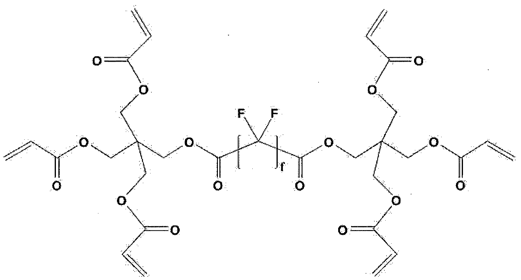
상기 화학식 15에서, f는 4 내지 10의 정수이다.
상기 광경화성을 갖는 코팅 조성물은 무기 미세 입자를 포함할 수 있으며, 저굴절층 또는 반사 방지 필름의 특성 등을 고려하여 통상적으로 알려진 무기 미세 입자를 포함할 수 있다. 이때 무기 미세 입자는 나노 미터 또는 마이크로 미터 단위의 직경을 갖는 무기 입자를 의미한다.
구체적으로, 상기 무기 미세 입자는 10 내지 100 nm 의 수평균 입경을 갖는 중공 실리카 입자일 수 있다. 상기 중공 실리카 입자는 입자의 표면 및 /또는 내부에 빈 공간이 존재하는 실리카 입자를 의미한다. 상기 중공 실리카 입자는 속이 찬 입자에 비하여 낮은 굴절율을 가져 우수한 반사 방지 특성을 나타낼 수 있다.
상기 중공 실리카 입자는 수평균 입경이 10 내지 100 nm, 바람직하게는 20 내지 70 nm, 보다 바람직하게는 30 내지 70 nm인 것일 수 있으며; 입자의 형상은 구상인 것이 바람직하지만, 부정형이라도 무방하다.
또한, 상기 중공형 무기 나노 입자로는 그 표면이 불소계 화합물로 코팅된 것을 단독으로 사용하거나, 불소계 화합물로 표면이 코팅되지 않는 중공형 무기 나노 입자와 흔합하여 사용할 수 있다. 상기 중공형 무기 나노 입자의 표면을 불소계 화합물로 코팅하면 표면 에너지를 보다 낮출 수 있으며, 이에 따라 상기 구현예의 광경화성을 갖는 코팅 조성물 내에서 상기 중공형 무기 나노 입자가 보다 균일하게 분포할 수 있고, 상기 광경화성을 갖는 코팅 조성물로부터 얻어지는 필름의 내구성이나 내스크래치성을 보다 높일 수 있다.
상기 중공형 무기 나노 입자의 표면에 불소계 화합물을 코팅하는 방법으로 통상적으로 알려진 입자 코팅 방법이나 중합 방법 등을 큰 제한 없이 사용할 수 있으며, 예를 들어 상기 중공형 무기 나노 입자 및 불소계 화합물을 물과 촉매의 존재 하에서 졸-겔 반웅 시켜서 가수 분해 및 축합 반웅을 통하여 상기 중공형 무기 나노 입자의 표면에 불소계 화합물을 결합시킬 수 있다.
그리고, 상기 중공 실리카 입자는 소정의 분산매에 분산된 콜로이드상으로 조성물에 포함될 수 있다. 상기 중공 실리카 입자를 포함하는 콜로이드상은 분산매로 유기 용매를 포함할수 있다.
이때, 상기 중공 실리카는 상기 유기 용매에 보다 용이하게 분산되기 위해서 표면에 치환된 소정의 작용기를 포함할 수 있다. 상기 중공 실리카 입자 표면에 치환 가능한 유기 작용기의 예가 크게 한정되는 것은 아니며, 예를 들어 (메타)아크릴레이트기, 비닐기, 히드록시기, 아민기, 알릴기 (al lyl ) , 에폭시기, 히드록시기, 이소시아네이트기, 아민기, 또는 불소 등이 상기 중공 실리카 표면에 치환될 수 있다.
상기 중공 실리카 입자의 콜로이드상에서 중공 실리카 입자의 고형분 함량은 상기 일 구현예의 광경화성을 갖는 코팅 조성물 중 중공 실리카의 함량 범위나 상기 광경화성을 갖는 코팅 조성물의 점도 등을 고려하여 결정될 수 있으며, 예를 들어 상기 콜로이드상 중 상기 중공 실리카 입자의 고형분 함량은 5중량 %내지 60중량 %일 수 있다.
여기서, 상기 분산매 중 유기 용매로는 메탄올, 이소프로필알코을, 에틸렌글리콜, 부탄올 등의 알코을류; 메틸에틸케톤, 메틸이소부틸케톤
등의 케톤류; 를루엔, 자일렌 등의 방향족 탄화수소류; 디메틸포름아미드. 디메틸아세트아미드, N-메틸피롤리돈 등의 아미드류; 초산에틸, 초산부틸 감마부틸로락톤 등의 에스테르류; 테트라하이드로퓨란, 1 , 4-디옥산 등의 에테르류; 또는 이들의 흔합물이 포함될 수 있다.
상기 저굴절층 제조를 위한 광경화성 코팅 조성물은 상기 광중합성 화합물 100중량부에 대하여 상기 중공 실리카 입자 10 내지 320중량부, 또는 50 내지 200중량부를 포함할 수 있다. 상기 중공 입자가 과량으로 첨가될 경우 바인더의 함량 저하로 인하여 코팅막의 내스크래치성이나 내마모성이 저하될 수 있다.
한편, 상기 광중합 개시제로는 광경화성 수지 조성물에 사용될 수 있는 것으로 알려진 화합물이면 크게 제한 없이 사용 가능하며, 구체적으로 벤조 페논계 화합물, 아세토페논계 화합물, 비이미다졸계 화합물, 트리아진계 화합물, 옥심계 화합물 또는 이들의 2종 이상의 흔합물을 사용할 수 있다.
상기 광중합성 화합물 100중량부에 대하여, 상기 광중합 개시제는
0. 1 내지 100중량부의 함량으로 사용될 수 있다. 상기 광중합 개시제의 양이 너무 작으면, 상기 광경화성을 갖는 코팅 조성물의 광경화 단계에서 미경화되어 잔류하는 물질이 발행할 수 있다. 상기 광중합 개시제의 양이 너무 많으면, 미반응 개시제가 불순물로 잔류하거나 가교 밀도가 낮아져서 제조되는 필름의 기계적 물성이 저하되거나 반사율이 크게 높아질 수 있다. 한편, 상기 광경화성을 갖는 코팅 조성물은 유기 용매를 더 포함할 수 있다.
상기 유기 용매의 비제한적인 예를 들면 케톤류, 알코올류, 아세테이트류 및 에테르류, 또는 이들의 2종 이상의 흔합물을 들 수 있다. 이러한 유기 용매의 구체적인 예로는, 메틸에틸케논, 메틸이소부틸케톤, 아세틸아세톤 또는 이소부틸케톤 등의 케톤류; 메탄을, 에탄올, n-프로판을, i-프로판올, n-부탄올, i_부탄올, 또는 t_부탄올 등의 알코올류; 에틸아세테이트, i—프로필아세테이트, 또는 폴리에틸렌글리콜 모노메틸에테르 아세테이트 등의 아세테이트류; 테트라하이드로퓨란 또는 프로필렌글라이콜 모노메틸에테르 등의 에테르류; 또는 이들의 2종 이상의
흔합물을 들 수 있다.
상기 유기 용매는 상기 광경화성을 갖는 코팅 조성물에 포함되는 각 성분들을 흔합하는 시기에 첨가되거나 각 성분들이 유기 용매에 분산 또는 흔합된 상태로 첨가되면서 상기 광경화성을 갖는 코팅 조성물에 포함될 수 있다. 상기 광경화성을 갖는 코팅 조성물 중 유기 용매의 함량이 너무 작으면, 상기 광경화성을 갖는 코팅 조성물의 흐름성이 저하되어 최종 제조되는 필름에 줄무늬가 생기는 등 불량이 발생할 수 있다. 또한, 상기 유기 용매의 과량 첨가시 고형분 함량이 낮아져, 코팅 및 성막이 층분히 되지 않아서 필름의 물성이나 표면 특성이 저하될 수 있고, 건조 및 경화 과정에서 불량이 발생할 수 있다. 이에 따라, 상기 광경화성을 갖는 코팅 조성물은 포함되는 성분들의 전체 고형분의 농도가 1중량 % 내지 50중량 %, 또는 2 내지 20중량 %가 되도록 유기 용매를 포함할 수 있다. 한편, 상기 반사방지 필름은 상기 하드 코팅 조성물을 기재의 일면에 도포하고 건조, 광경화를 거친 후 저굴절층 형성용 광경화성 코팅 조성물을 상기 형성된 하드 코팅층 위에 도포하고 도포된 결과물을 광경화함으로서 얻어질 수 있다. 이때 상기 하드 코팅층은 반경화가 될 수 있으며 저굴절층을 경화시 최종 경화되는 방법이 가장 바람직하다.
상기 기재의 구체적인 종류나 두께는 크게 한정되는 것은 아니며, 저굴절층 또는 반사 방지 필름의 제조에 사용되는 것으로 알려진 기재를 큰 제한 없이 사용할 수 있다. 예를 들어, 상기 기재로 트리아세틸셀를로오스 (TAC) 필름, 디아세틸셀를로오스 필름, 아세틸프로필셀를로오스 필름, 아세틸부틸셀를로오스 필름과 같은 셀롤로오스 필름; 폴리에틸렌 테레프탈레이트 필름, 폴리에틸렌 나프탈레이트 필름과 같은 폴리에스테르 필름; 폴리비닐아세테이트 필름; 폴리카보네이트 필름; 폴리술폰 필름; 폴리아크릴 필름; 폴리아미드 필름; 폴리스티렌 필름; 또는 위상차 필름 등을 사용할 수 있으나, 이에 한정되는 것은 아니다.
상기 광경화성 코팅 조성물을 도포하는데 통상적으로 사용되는 방법 및 장치를 별 다른 제한 없이 사용할 수 있으며, 예를 들어, Meyer bar
등의 바 코팅법, 그라비아 코팅법, 2 rol l reverse 코팅법, vacuum s lot die 코팅법, 2 rol l 코팅밥등을사용할 수 있다.
상기 광경화성을 갖는 코팅 조성물을 광경화 시키는 단계에서는 200-400 nm 파장의 자외선 또는 가시 광선을 조사할 수 있고 조사시 노광량은 100 내지 4 000 mJ/cin2 이 바람직하다. 노광 시간도 특별히 한정되는 것이 아니고, 사용되는 노광 장치, 조사 광선의 파장 또는 노광량에 따라 적절히 변화시킬 수 있다.
또한, 상기 광경화성을 갖는 코팅 조성물을 광경화시키는 단계에서는 개시제가 산소에 의해 분해되는 것을 방지하기 위해 질소 퍼징 등을 할 수 있다.
한편, 최종 건조된 상기 하드 코팅층은 5 초과 10 미만의 두께를 가질 수 있다. 상기 하드 코팅층의 두께가 5 이하이면 유기 입자 혹은 무기 입자가 웅집되어 반사 방지 필름 표면 상에 높이가 높으면서 불규칙적으로 분포하는 피크들이 존재할 수 있고, 상기 하드 코팅층의 두께가 10 이상이면 코팅층이 두꺼워 코팅 필름 취급시 크랙이 발생하기 쉬운 단점이 있다. 이때, 저굴절층은 Iran 내지 300 nm , 또는 50nm 내지 200 nm의 두께를 가질 수 있다. 상술한 범위로 하드 코팅층 및 저굴절층의 두께를 조절함으로써, 특정 범위의 거칠기 첨도 (Rku) 및 스웨디쉬 높이 (H)의 구현이 가능하여 반사 방지 필름의 눈부심 방지 기능을 유지하면서도 이미지의 선명도를 높일 수 있다. 한편, 발명의 다른 구현예에 따르면, 상술한 반사 방지 필름을 포함하는 디스플레이 장치가 제공될 수 있다.
상기 디스플레이 장치는 서로 대향하는 1쌍의 편광판; 상기 1쌍의 편광판 사이에 순차적으로 적층된 박막트랜지스터, 컬러필터 및 액정셀; 및 백라이트 유닛을 포함하는 액정디스플레이 장치일 수 있다.
도 la 및 lb에 각각 본 발명의 일 실시예에 따른 반사 방지 필름이 구비된 일반 TFT 디스플레이 장치 및 COT 패널 디스플레이 장치의 개략적인 구조를 나타내었다. 또한, 도 la 및 lb에 나타낸 구조 대신, 편광판 및 백라이트 유닛 사이에 상기 반사 방지 필름이 구비된 구조또한 가능하다.
【발명의 효과】
본 발명에 따르면, 고해상도 디스플레이에 적용시 스파클링 현상이 적고 시인성이 우수하며 디스플레이 제작시 작업성이 우수한 반사 방지 필름과 우수한 외부 블렉시감 및 명암비 등의 광특성 및 높은 화면의 선명도를 제공하는 디스플레이 장치가 제공될 수 있다.
상기 반사 방지 필름은 고해상도 디스플레이에 적용되어 패널 불량 은폐력이 높고 반사방지 성능과 시인성이 우수한 특성을 제공할 수 있다. 특히, 패널 내부 반사을이 높은 COT 패널에 적용하여 반사방지 성능을 발현할 수 있다.
【도면의 간단한 설명】
도 la는 실시예 1의 반사 방지 필름이 설치된 일반 TFT 디스플레이 장치의 단면을 개략적으로 나타낸 것이다.
도 lb는 실시예 1의 반사 방지 필름이 설치된 COT 패널 디스플레이 장치의 단면을 개략적으로 나타낸 것이다.
도 2는 실시예 3에서 제조된 하드 코팅층 표면의 광학현미경 사진 (반사모드, 배율: 10 배)이다.
도 3은 실시예 4에서 제조된 하드 코팅층 표면의 광학현미경 사진 (반사모드, 배율: 10 비] )이다.
도 4는 실시예 1에서 제조된 반사 방지 필름 표면의 광학현미경 사진 (반사모드, 배율: 20 배)이다.
도 5는 비교예 4에서 제조된 반사 방지 필름 표면의 광학현미경 사진 (반사모드, 배율: 10 배)이다.
【발명을 실시하기 위한 구체적인 내용】
발명의 구체적인 구현예를 하기의 실시예에서 보다 상세하게 설명한다. 단, 하기의 실시예는 발명의 구체적인 구현예를 예시하는 것일 뿐, 발명의 구체적인 구현예의 내용이 하기의 실시예에 의하여 한정되는 것은 아니다.
<제조예: 하드 코팅 조성물 및 저굴절층 형성용 광경화성 코팅 조성물의 제조 >
( 1) 하드 코팅 조성물의 제조
하기 표 1 의 성분을 균일하게 혼합하여 하드 코팅 조성물을 제조하였다. 표 1 에서 사용된 모든 성분의 함량은 g 단위로 나타내었다. 또한, 하기 표 1 에서 입자 총합은 유기 미립자 및 무기 나노 입자의 합을 의미한다ᅳ
[표 1]
비교 비교 비교 제조예 제조예 제조예 제조예
제조예 제조예 제조예 1 2 3 4
1 2 3
UA-306T 4.25 4.26 4.26 4.80 4.83 4.79 4.40 바인 8BR-500 7.96 7.99 8.00 8.95 9.01 8.99 8. 17 더 TMPTA 19.72 19.78 22. 16 22.30
PETA 19.81 22.27 20. 12 개시
1184 2.04 2.04 2.04 2.54 2.30 2.30 2.27 제
레벨
BY -300 0.21 0.21 0.22 0.27 0.24 0.24 0.25 링제
IPA 32.55 43.40 32.69 40.06 30.30 30.25 62.89 용매
EtOH 32. 15 21.50 32.29 20.02 30.30 30.25 유기
미립 미립자 1 0.38 0.64 0.54 1.00 0.48 0.60 0.95 자
무기 실리카 1 0.54
나노 실리카 2
0.21 0. 16 0. 16 0.20 0.24 0.30 0.95 입자 분산액
총합 100.0 100.0 100.0 100.0 100.0 100.0 100.0 고형분 (wt¾>) 35.306 35.087 35.026 39.920 39.400 39.494 37. 110 바인더 총합
31.927 32.036 32.067 35.910 36. 140 36.054 32.690
(wt%)
분산액 내 0.063 0.048 0.048 0.060 0.072 0.090 0.285
실리카 2함량
(g)
입자총합 (wt« 0.983 0.688 0.588 1.060 0.552 0.690 1.235 입자총중량대비
실리카 2의 중량 6.409 6.977 8.163 5.660 13.043 13.043 23.077 (wt%)
1) PETA: Pentaerythritol triacrylate (분자량 298 g/mol)
2) TMPTA: Trimethylolpropane triacrylate (분자량 296 g/mol)
3) 8BR-500: 우레탄계 아크릴 올리고머, 분자량 250,000 g/mol, Taisei Fine Chemical사 제품.
4) UA-306T: 우레탄계 아크릴 올리고머, 분자량 1,000 g/mol, kyoeisha사 제품.
5) I184(Irgacure 184): 광개시제, Ciba사 제품.
6) BYK-300: 레벨링제 Tego 사 제품.
7) IPA(Isopropyl alcohol)
8) Et0H(Ethyl alcohol)
9) 미립자 1: 부피 평균입경 2 卿이고, 굴절율이 1.555 인 구형의 유기 미립자인 아크릴-스티렌공중합 수지, Techpolymer, Sekisui Plastic사 제품.
10) 실리카 1: 부피 평균 입경 100 nm 인 실리카 입자, X24-9600A,
Shinetsu사 제품.
11) 실리카 2 분산액: 메탄을에 30 %의 비율로 분산된 부피 평균 입경 12 nm인 나노 실리카의 분산액, MA-ST, Nissan Chemical 사 제품. (2) 저굴절률층 형성용 광경화성 코팅 조성물의 제조
상기 표 2 의 성분을 흔합하고, MIBKOnethyl isobutyl ketone) 및 디아세톤알콜 (DM)의 1:1 흔합 용액 (중량비)에 고형분이 5 %가 되도록 희석하여, 저굴절층 형성용 광경화성 코팅 조성물을 제조하였다. 표 2 에서 사용된 모든 성분의 함량은 g 단위로 나타내었다.
[표 2]

1) 디펜타에리스리를 펜타아크릴레이트, 분자량 524.51 g/mol , yoei sha Λ1- 게품.
2) THRULYA 4320: 중공 실리카 분산액, MIBK용매 중 고형분 20 wt , 촉매화성 사 제품.
3) RS907 : 광반응성 작용기를 포함한 불소계 화합물, MIBK 용매 중 고형분 30중량 %으로 희석됨, DIC사 제품.
4) EP0408 : 폴리실세스퀴옥산, Hybr id Pl ast i cs 사 제품
<실시예 및 비교예: 반사 방지 필름의 제조 >
하기 표 3 에 나타난 바와 같이 , 트리아세틸 셀를로우스 (TAC) 필름에 Meyer Bar 로 상기 제조예에서 각각 제조된 하드 코팅 조성물을 도포하고 90°C에서 1 분 건조한 이후, 150 mJ/cuf의 자외선을 조사하여 하드 코팅층을 제조하였다.
이 후 상기 제조예에서 각각 제조된 저굴절층 제조용 수지 조성물을 Meyer Bar #3 으로 하드 코팅층 위에 도포 하고, 90°C에서 1 분 건조하였다. 그리고, 질소 퍼징하에서 상기 건조물에 180 mJ/cuf의 자외선을 조사하여 110 ran의 두께를 갖는 저굴절층을 형성함으로서 눈부심 /반사 방지 필름을 제조하였다.
[표 3]
실시예 실시예 실시예 실시예 비교예 비교예 비교예 비교예 참고예
1 2 3 4 1 2 3 4 1
TAC 필름
두께 60 60 60 60 60 60 60 60 60 iim)
하드 비교 비교 비교
제조예 제조예 제조예 제조예 제조예 제조예 코팅층 제조예 제조예 제조예
1 2 3 4 1 1 조성물 1 2 3
하드
코팅층
6 6 6 7 4 6 6 6 6 두께
"m)
참고 저굴절층 제조예 제조예 제조예 제조예. 제조예 제조예 제조예 제조예
제조예 조성물 5 5 5 5 5 5 5 - 5
1
<실험예: 하드코팅층 및 반사방지 필름의 물성 측정 >
상기 제조된 하드 코팅층의 물성 및 이를 포함하는 반사 방지 필름의 물성을 하기의 방법에 따라측정하고, 이를 표 4에 나타내었다. 1. 하드 코팅층의 표면 분석
실시예 3 및 4 에서 제조된 하드 코팅층의 표면을 분석하기 위하여, 하드 코팅층이 형성된 필름의 뒷면에 검정색 필름을 접착시킨 후 하드 코팅층 표면이 광학 현미경 (BX-51 , Olympus 사 제조)의 —대물렌즈 쪽으로 향하게 올려 놓은 후, 대물렌즈의 배율을 10 배로 설정하여 상기 하드 코팅층의 표면을 측정하였다. 측정한 광학 현미경 사진을 도 2 및 도 3 에 각각 나타내었다.
도 2 및 도 3 을 참조하면, 실시예 3 및 4 를 통해 제조된 하드 코팅층의 표면의 요철 형상은 피크의 높이가 낮으면서 밸리는 얕고 넓게 퍼져있는 구조를 가짐을 알 수 있다. 또한, 하드 코팅층의 두께가 두꺼워서, 입자들이 웅집되어 형성된 돌기와 같은 요철들이 존재하지 않을 뿐만 아니라, 피크들의 크기가 작고 높이가 낮아 비교적 균일한 요철의 크기
분포를 나타냄을 확인할수 있다.
2. 반사 방지 필름의 투광도, 내부 헤이즈 및 외부 헤이즈 측정 반사 방지 필름의 전체 헤이즈는 내부 헤이즈와 외부 헤이즈의 합이며, 다음의 방법으로 전체 헤이즈 및 내부 헤이즈를 측정한 후, 외부 헤이즈는 전체 헤이즈와 내부 헤이즈의 차이로 구할 수 있다. 구체적으로, 헤이즈 측정기 (HM-150 , A 광원, 무라카미 사 제조)를 사용하여, JIS K 7361 규격에 의해 투광도를 3 회 측정하고, JIS K 7105 규격에 의해 헤이즈를 3 회 측정한 후, 각각의 평균값을 계산하여 투광도와 전체 헤이즈를 구하였다. 또한, 제조된 코팅층의 표면을 편평하게 만들어 주기 위해 헤이즈가 0 인 접착제를 표면에 붙여 외부 요철이 접착제에 묻히도록 한 후 상기 헤이즈 측정기로 헤이즈를 3 회 측정한 후 평균값을 계산하여 내부 헤이즈를 구하였다. 이후, 구해진 전체 헤이즈 값에서 내부 헤이즈 값을 빼서 외부 헤이즈를 구하였다.
3. 반사 방지 필름의 거칠기 첨도 (Rku) 및 스웨디쉬 높이 (H) 측정 표면 요철의 거칠기 첨도 및 스웨디쉬 높이는 백색광 삼차원 광학간섭 프로파일 (3D opt ical prof i ler , 모델명: NewView 7300 , Zygo 사 제조) 장비를 이용하여 측정한다. 이때 사용하는 렌즈 배율은 10 배, 0.5 배 줌 측정 조건으로 하여 1.40 X 1.05 腿 2영역을 측정하였다.
제조된 반사 방지 필름을 샘플 스테이지에 편평한 상태로 을린 후 opt ical prof i ler 이미지를 앋은 후 분석을 진행하였다. 분석 이후 상기 일반식 1에 따른 거칠기 첨도 (Rku) 및 스웨디쉬 높이 (H)를 계산하였다. 4. 반사 방지 필름의 평균 반사율측정
SHIMADZU사의 Sol idSpec 3700를 이용하여 평균 반사율을 측정하였다. 구체적으로, 반사 방지 필름의 하드 코팅층이 형성되지 않은 면에 빛이 투과하지 못하도록 블랙 테이프 (Vinyl tape 472 Black, 3M 사 제조)를 붙이고, sampl ing interval 1 nm, t ime constant 0.1 sec , s l i t width 20 nm, medium scanning speed 로 측정 조건을 고정한 후, 100T 모드를
적용하여 상온에서 상기 반사 방지 필름에 380 nm 내지 780 nm 파장 영역의 광을 조사하여 측정하였다.
5. 내스크래치성 측정
스틸울 (#0000)에 하중을 걸고 27 rpm 의 속도로 10 회 왕복하며 실시예 및 비교예에서 얻어진 반사 방지 필름의 표면을 문질렀다. 육안으로 관찰되는 1 cm 이하 의 스크래치가 1 개 이하가 되는 최대 하중을 확인하여 내스크래치성을 평가하였다.
6. 반사 방자필름의 불량요철 평가
실시예 및 비교예에서 제조된 반사 방지 필름의 불량 요철 유무를 확인하기 위하여, 반사 방지 필름의 하드 코팅층이 형성되지 않은 면에 빛이 투과하지 못하도록 블랙 테이프 (Vinyl tape 472 Black, 3M 사 제조)를 붙인 후, 광학 현미경 (BX-51 , Olympus 사 제조)을 사용하여 반사 이미지를 촬영하였다. 촬영한 이미지의 크기는 640 X480 pixel 이며, 배율은 10 배 흑은 20 배 중 선택할 수 있다. 광량은 광학 현미경 상부에서 나오는 최대 광량의 50%내지 100% 범위 내에서 조절되었다.
사용된 이미지에서 반사 방지 필름 표면에 존재하는 레인보우 얼룩 유무를 관찰하여, 하기 기준에 따라 평가하였다. 이러한 레인보우 얼룩이 반사 방지 필름에 존재하는 경우 후속 공정에서 불량 화소를 유발할 수 있는 원인이 될 수 있어, 존재하지 않는 것이 바람직하다. 평가 결과 중 실시예 1 및 비교예 4 의 반사 방지 필름에 대한 광학 현미경 사진을 각각 도 4 및 5에 나타내었다.
<측정 기준 >
X: 레인보우 얼룩이 존재하지 않음.
Δ : 레인보우 얼룩이 1 내지 3 개 이하로 존재함 (배율 20배 기준) .
O : 레인보우 얼룩이 3 개 초과로 존재함 (배율 20배 기준) .
[표 4]
실시 실시 실시 실시 비교 비교 비교 비교 참고 예 1 예 2 예 3 예 4 예 1 예 2 예 3 예 4 예
1 비교 비교 비교 하드 코팅층 제조 제조 제조 제조 제조 제조 제조 제조 제조 조성물 예 1 예 2 예 3 예 4 예 1 예 1 예 1 예 2 예 3 하드 코팅층
6 6 6 7 4 6 6 6 6 두께 (im)
참고 제조 제조 제조 제조 제조 제조 제조 제조 저굴절층 제조 예 예 예 예 예 예 예 예 조성물 예
5 5 5 5 5 5 5 5
1
Rku 3.66 5.41 3.65 5.17 3.22 3.41 3.16 3.12 3.71
H
118.9 72.1 99.3 74.6 257.2 239.2 212.3 290.5 102.7 (nm)
투광도
95.4 95.1 95.1 95.3 95.2 95.2 95.2 95.4 95.3 ( )
전체 혜이즈
2.6 1.8 2.2 2.3 1.9 2.1 2.7 2.4 2.6 ( )
내부 헤이즈
2.4 1.7 2.1 2.2 1.4 1.8 2.2 1.8 2.4 (%)
외부 헤이즈
0.2 0.1 0.1 0.1 0.5 0.3 0.5 0.6 0.2 (%)
평균 반사율
1.27 1.27 1.27 1.27 1.27 1.27 1.27 1.27 1.27 (%)
레인보우
X X X X O Δ O 0 X 존재여부
내스크래치
성 350 350 350 350 350 350 350 350 150 (g) 상기 표 4 에서 확인되는 바와 같이, 동일한 하드 코팅층 조성물을
사용하더라도 하드 코팅층의 두께가 5 이하인 반사 방지 필름 (비교예 1), 하드 코팅층 조성물 내 12 nm 직경을 갖는 나노 실리카 (무기 나노 입자)의 함량이 너무 높은 반사 방지 필름 (비교예 2 내지 4)의 경우, 본 발명의 거칠기 첨도 (Rku) 및 스웨디쉬 높이 (H)의 범위를 동시에 만족하지 못함을 알 수 있다.
반면, 실시예의 반사 방지 필름은 3.5 초과 6 미만의 거칠기 첨도 (Rku) 및 200 nm 미만의 스웨디쉬 높이 (H)를 동시에 만족하면서, 낮은 외부 헤이즈를 나타냄과 동시에 우수한 내스크래치성을 확보할 수 있다는 점이 확인된다.
또한, 광반웅성 작용기를 포함한 불소계 화합물 및 반웅성 작용기가
1 이상 치환된 폴리실세스퀴옥산을 동시에 포함하지 않는 저굴절층 조성을 갖는 참고예 1 경우, 본 발명의 거칠기 첨도 (Rku) 및 스웨디쉬 높이 (H)의 범위는 만족하나 실시예에 비하여 내스크래치성은 저하됨을 알 수 있다. 더욱이, 도 4 및 5 를 참조하면, 상기와 같은 물성을 갖는 실시예의 반사 방지 필름은, 비교예의 반사 방지 필름과 달리 레인 보우 얼룩이 존재하지 않아, 불량 화소가 존재하지 않는 액정 디스플레이 장치를 구현할 수 있다.
Claims
【특허청구범위】
【청구항 1 1
하드 코팅층; 및 상기 하드 코팅층에 형성된 저굴절층;을 포함하고, 표면의 요철 형상의 거칠기 첨도 (Rku)가 3.5 초과 6 미만이고, 스웨디쉬 높이 (H)가 20 nm초과 200 nm 미만이며,
380 nm 내지 780 nm 파장 영역에서의 투광도가 94% 이상인, 반사 방지 필름.
【청구항 2】
제 1항에 있어서,
상기 반사 방지 필름의 표면의 요철 형상의 거칠기 첨도 (Rku) 및 스웨디쉬 높이 (H)는 비접촉 표면형상측정기 (3D Opt i cal Prof i ler)를 이용하여 측정한 결과인, 반사 방지 필름. 【청구항 3】
제 1항에 있어서,
상기 반사 방지 필름의 380 nm 내지 780 nm 파장 영역에서의 평균 반사율이 5%미만인, 반사 방지 필름. 【청구항 4】
게 1항에 있어서,
상기 반사 방지 필름의 내부 헤이즈가 0 초과 10% 미만인, 반사 방지 필름. 【청구항 5】
제 1항에 있어서,
상기 반사 방지 필름의 외부 헤이즈가 0 초과 0.5% 미만인, 반사 방지 필름. 【청구항 6】
제 1항에 있어서,
상기 하드 코팅층은 광중합성 화합물의 (공)중합체를 포함하는 바인더 수지 및 상기 바인더 수지에 분산된 유기 또는 무기 미립자;를 포함하는 반사 방지 필름.
【청구항 7】
제 6항에 있어서,
상기 하드 코팅층은 상기 광중합성 화합물의 (공)중합체 100중량부 대비 상기 유기 또는 무기 미립자 1 내지 20중량부를 포함하는, 반사 방지 필름
【청구항 8】
게 6항에 있어서,
상기 하드 코팅층은 상기 유기 또는 무기 미립자 및 무기 나노 입자의 총중량을 기준으로 1 nm 내지 50 nm 의 직경을 갖는 무기 나노 입자 3 내지 10 중량 %를 더 포함하는, 반사 방지 필름.
【청구항 9】
제 8항에 있어서,
상기 하드 코팅층은 50 nm 초과 120 nm 이하의 직경을 갖는 무기 나노 입자를 더 포함하는, 반사 방지 필름.
【청구항 10】
제 1항에 있어서,
상기 저굴절층은 광중합성 화합물; 광반웅성 작용기를 포함한 불소계 화합물; 및 반웅성 작용기가 1이상 치환된 폴리실세스퀴옥산 (polysi lsesquioxane) ; 간의 가교 중합체를 포함하는 바인더 수지와 상기 바인더 수지에 분산된 무기 미세 입자를 포함하는, 반사 방지 필름.
【청구항 111
제 10항에 있어서,
상기 폴리실세스퀴옥산에 치환되는 반웅성 작용기는 알코을, 아민, 카르복실산, 에폭사이드, 이미드, (메타)아크릴레이트, 니트릴, 노보넨, 올레핀, 폴리에틸렌글리콜, 싸이올 및 비닐기로 이루어진 군에서 선택된 1종 이상의 작용기를 포함하는, 반사 방지 필름.
【청구항 12】
제 11항에 있어서,
상기 반웅성 작용기가 1이상 치환된 폴리실세스퀴옥산은 탄소수 1 내지 30의 직쇄 또는 분지쇄의 알킬기, 탄소수 6 내지 30의 사이클로핵실기 및 탄소수 6 내지 30의 아릴기로 이루어진 군에서 선택된 1종 이상의 미반웅성 작용기가 1이상 더 치환되는, 반사 방지 필름. 【청구항 13】
제 10항에 있어서,
상기 반웅성 작용기가 1이상 치환된 폴리실세스퀴옥산은 반웅성 작용기가 1이상 치환되고 케이지 (cage)구조를 갖는 다면체 올리고머 실세스퀴옥산 (Polyhedral Ol igomer ic Si l sesquioxane)을 포함하는, 반사 방지 필름.
【청구항 14】
제 13항에 있어서,
상기 케이지 (cage)구조를 갖는 다면체 올리고머 실세스퀴옥산의 실리콘들 중 적어도 1개 이상에는 반웅성 작용기가 치환되고 상기 반웅성 작용기가 치환되지 않은 나머지 실리콘들에는 비반웅성 작용기가 치환되는, 반사 방지 필름.
【청구항 15]
제 14항에 있어서
상기 폴리실세스퀴옥산에 치환된 비작용성 반응기 대비 반응성 작용기의 몰비 (molar rat io)가 0.20 이상인, 반사 방지 필름.
【청구항 16】
제 10항에 있어서,
상기 광중합성 화합물은 (메타)아크릴레이트 또는 비닐기를 포함하는 단량체 또는 올리고머를 포함하는, 반사 방지 필름.
【청구항 17]
제 10항에 있어서,
상기 불소계 화합물에 포함되는 광반웅성 작용기는
(메타)아크릴레이트기, 에폭사이드기, 비닐기 (Vinyl ) 및 싸이올기 (Thiol )로 이루어진 군에서 선택된 1종 이상인, 반사 방지 필름. 【청구항 18】
제 10항에 있어서,
상기 광반웅성 작용기를 포함한 불소계 화합물은 1 중량 % 내지 25 중량 %의 불소 함량을 갖고,
i ) 하나 이상의 광반웅성 작용기가 치환되고, 적어도 하나의 탄소에 1이상의 불소가 치환된 지방족 화합물 또는 지방족 고리 화합물; i i ) 1 이상의 광반웅성 작용기로 치환되고, 적어도 하나의 수소가 불소로 치환되고, 하나 이상의 탄소가 규소로 치환된 헤테로 (hetero) 지방족 화합물 또는 헤테로 (hetero)지방족 고리 화합물; i i i ) 하나 이상의 광반웅성 작용기가 치환되고, 적어도 하나의 실리콘에 1이상의 불소가 치환된 폴리디알킬실록산계 고분자; 및 iv) 1 이상의 광반웅성 작용기로 치환되고 적어도 하나의 수소가 불소로 치환된 폴리에테르 화합물;로 이루어진 군에서 선택된 1종 이상을 포함하는, 반사 방지 필름.
【청구항 19]
제 10항에 있어서
상기 무기 미세 입자는 10 내지 100 nm 의 수평균 입경을 갖는 중공 실리카 입자인, 반사 방지 필름.
【청구항 20]
제 10항에 있어서,
상기 저굴절층은 상기 광증합성 화합물 100 중량부에 대하여 상기 광반웅성 작용기를 포함한 불소계 화합물 1 내지 75 중량부, 상기 반응성 작용기가 1이상 치환된 폴리실세스퀴옥산 (polys i l sesqui oxane) 0.5 내지 25 중량부 및 상기 무기 미세 입자 10 내지 320 중량부를 포함하는, 반사 방지 필름.
【청구항 21】
제 1항에 있어서,
상기 하드 코팅층은 5 urn초과 10 im 미만의 두께를 가지며, 상기 저굴절층은 Iran 내지 300 ran의 두께를 갖는, 반사 방지 필름.
【청구항 22]
게 1항 내지 제 21항 중 어느 한 항에 따른 반사 방지 필름을 포함하는 디스플레이 장치 .
Priority Applications (4)
| Application Number | Priority Date | Filing Date | Title |
|---|---|---|---|
| CN201780003067.2A CN108027455B (zh) | 2016-03-14 | 2017-02-10 | 减反射膜和显示装置 |
| JP2018518416A JP2018533065A (ja) | 2016-03-14 | 2017-02-10 | 反射防止フィルムおよびディスプレイ装置 |
| EP17766893.6A EP3318905A4 (en) | 2016-03-14 | 2017-02-10 | Anti-reflective film and display apparatus |
| US15/751,767 US10689523B2 (en) | 2016-03-14 | 2017-02-10 | Antireflection film and display device |
Applications Claiming Priority (4)
| Application Number | Priority Date | Filing Date | Title |
|---|---|---|---|
| KR20160030396 | 2016-03-14 | ||
| KR10-2016-0030396 | 2016-03-14 | ||
| KR10-2016-0036378 | 2016-03-25 | ||
| KR20160036378 | 2016-03-25 |
Publications (1)
| Publication Number | Publication Date |
|---|---|
| WO2017159992A1 true WO2017159992A1 (ko) | 2017-09-21 |
Family
ID=59851576
Family Applications (1)
| Application Number | Title | Priority Date | Filing Date |
|---|---|---|---|
| PCT/KR2017/001455 Ceased WO2017159992A1 (ko) | 2016-03-14 | 2017-02-10 | 반사 방지 필름 및 디스플레이 장치 |
Country Status (7)
| Country | Link |
|---|---|
| US (1) | US10689523B2 (ko) |
| EP (1) | EP3318905A4 (ko) |
| JP (2) | JP2018533065A (ko) |
| KR (1) | KR101948821B1 (ko) |
| CN (1) | CN108027455B (ko) |
| TW (1) | TWI630409B (ko) |
| WO (1) | WO2017159992A1 (ko) |
Families Citing this family (15)
| Publication number | Priority date | Publication date | Assignee | Title |
|---|---|---|---|---|
| JP6789593B2 (ja) * | 2016-03-09 | 2020-11-25 | エルジー・ケム・リミテッド | 反射防止フィルム |
| KR101951863B1 (ko) | 2016-03-14 | 2019-02-25 | 주식회사 엘지화학 | 반사 방지 필름 및 디스플레이 장치 |
| KR101951864B1 (ko) * | 2016-03-14 | 2019-02-25 | 주식회사 엘지화학 | 반사 방지 필름 및 디스플레이 장치 |
| KR101948821B1 (ko) | 2016-03-14 | 2019-02-15 | 주식회사 엘지화학 | 반사 방지 필름 및 디스플레이 장치 |
| WO2019107924A1 (ko) * | 2017-11-28 | 2019-06-06 | 주식회사 엘지화학 | 디스플레이 패널용 시인성 개선 필름 및 이를 포함하는 디스플레이 장치 |
| KR102167662B1 (ko) | 2017-11-28 | 2020-10-19 | 주식회사 엘지화학 | 디스플레이 패널용 시인성 개선 필름 및 이를 포함하는 디스플레이 장치 |
| KR102280262B1 (ko) | 2018-05-18 | 2021-07-21 | 주식회사 엘지화학 | 반사 방지 필름, 편광판 및 디스플레이 장치 |
| KR102308952B1 (ko) * | 2018-11-02 | 2021-10-05 | 주식회사 엘지화학 | 투명 디스플레이 장치 |
| CN109825184A (zh) * | 2019-02-20 | 2019-05-31 | 宁波激智科技股份有限公司 | 一种具有高硬度和低反射率的硬化层的硬化涂布液及硬化膜 |
| US12083771B2 (en) * | 2019-03-29 | 2024-09-10 | Lg Chem, Ltd. | Optical laminate |
| KR102581428B1 (ko) | 2019-05-28 | 2023-09-21 | 주식회사 엘지화학 | 반사 방지 필름, 편광판 및 디스플레이 장치 |
| TWI740515B (zh) | 2019-12-23 | 2021-09-21 | 長春人造樹脂廠股份有限公司 | 液晶高分子膜及包含其之積層板 |
| TWI697549B (zh) | 2019-12-23 | 2020-07-01 | 長春人造樹脂廠股份有限公司 | 液晶高分子膜及包含其之積層板 |
| KR20230086238A (ko) * | 2021-12-08 | 2023-06-15 | 엘지디스플레이 주식회사 | 표시 장치 |
| CN121454662A (zh) * | 2022-04-27 | 2026-02-03 | 大日本印刷株式会社 | 光学膜、图像显示面板以及图像显示装置 |
Citations (5)
| Publication number | Priority date | Publication date | Assignee | Title |
|---|---|---|---|---|
| JPH0798401A (ja) * | 1993-09-28 | 1995-04-11 | Nitto Denko Corp | 反射防止膜及び反射防止部材 |
| JP2005156642A (ja) * | 2003-11-20 | 2005-06-16 | Fuji Photo Film Co Ltd | 反射防止フィルム、偏光板、及びそれを用いた画像表示装置 |
| KR20090077767A (ko) * | 2006-10-06 | 2009-07-15 | 도레이 카부시키가이샤 | 하드 코팅 필름, 그의 제조 방법 및 반사 방지 필름 |
| JP2009230045A (ja) * | 2008-03-25 | 2009-10-08 | Dainippon Printing Co Ltd | 反射防止積層体 |
| JP2010085759A (ja) * | 2008-09-30 | 2010-04-15 | Fujifilm Corp | 防眩フィルム、反射防止フィルム、偏光板及び画像表示装置 |
Family Cites Families (73)
| Publication number | Priority date | Publication date | Assignee | Title |
|---|---|---|---|---|
| JP3288536B2 (ja) | 1994-06-21 | 2002-06-04 | 日本碍子株式会社 | 排ガスフィルタおよびそれを使用した排ガス処理装置 |
| JPH09222504A (ja) | 1996-02-16 | 1997-08-26 | Dainippon Printing Co Ltd | 反射防止フイルム |
| JPH11109103A (ja) | 1997-10-02 | 1999-04-23 | Nikon Corp | 光学部材 |
| JP4081862B2 (ja) | 1998-07-06 | 2008-04-30 | 東レ株式会社 | 薄膜及びそれを利用した反射防止膜 |
| JP4506918B2 (ja) | 2000-07-04 | 2010-07-21 | Jsr株式会社 | 反射防止膜、反射防止膜を含む積層体、および反射防止膜の製造方法 |
| JP3862941B2 (ja) | 2000-07-21 | 2006-12-27 | リンテック株式会社 | 高精細防眩性ハードコートフィルム |
| JP2003034761A (ja) | 2001-04-27 | 2003-02-07 | Nippon Arc Co Ltd | ハードコート組成物およびハードコート製品 |
| JP2005070318A (ja) | 2003-08-22 | 2005-03-17 | Fuji Photo Film Co Ltd | 防眩性反射防止フィルムおよびその製造方法、偏光板並びに画像表示装置 |
| TW200517458A (en) | 2003-10-06 | 2005-06-01 | Dainippon Printing Co Ltd | Antiglare film |
| JP2006047504A (ja) * | 2004-08-02 | 2006-02-16 | Dainippon Printing Co Ltd | 反射防止積層体 |
| US20060093809A1 (en) | 2004-10-29 | 2006-05-04 | Hebrink Timothy J | Optical bodies and methods for making optical bodies |
| JP2006146027A (ja) | 2004-11-24 | 2006-06-08 | Konica Minolta Opto Inc | 防眩性反射防止フィルム、偏光板及び表示装置 |
| US7419707B2 (en) | 2005-02-21 | 2008-09-02 | Fujifilm Corporation | Coating composition for the formation of low refractive index layer, antireflection film, polarizing plate and liquid crystal display device |
| KR20070017040A (ko) * | 2005-08-03 | 2007-02-08 | 후지필름 홀딩스 가부시끼가이샤 | 반사방지 필름, 편광판 및 영상 표시 장치 |
| JP2007047701A (ja) | 2005-08-12 | 2007-02-22 | Ricoh Co Ltd | 光学素子 |
| JP2007127855A (ja) | 2005-11-04 | 2007-05-24 | Konica Minolta Holdings Inc | 光学素子 |
| JP4844254B2 (ja) | 2006-06-20 | 2011-12-28 | 住友化学株式会社 | 防眩フィルム及び画像表示装置 |
| JP2008040063A (ja) | 2006-08-04 | 2008-02-21 | Toppan Printing Co Ltd | 防眩性光拡散部材 |
| US8047662B2 (en) | 2007-03-27 | 2011-11-01 | Fujifilm Corporation | Antiglare film, polarizing plate and image display device |
| JP2009042351A (ja) * | 2007-08-07 | 2009-02-26 | Konica Minolta Opto Inc | 光学フィルム、偏光板及び表示装置 |
| JP2009098657A (ja) | 2007-09-26 | 2009-05-07 | Fujifilm Corp | 液晶表示装置 |
| JP4539759B2 (ja) | 2007-10-01 | 2010-09-08 | オムロン株式会社 | 反射防止シート、表示素子及びディスプレイ装置 |
| JP5098571B2 (ja) | 2007-10-25 | 2012-12-12 | 大日本印刷株式会社 | 光学積層体、偏光板及び画像表示装置 |
| JP2009186776A (ja) | 2008-02-06 | 2009-08-20 | Sumitomo Osaka Cement Co Ltd | ハードコート膜およびその製造方法並びにハードコート膜を備えた光学機能膜および光学レンズ |
| JP2009204728A (ja) | 2008-02-26 | 2009-09-10 | Nof Corp | 防眩性積層体及びそれを備えるディスプレイ |
| KR20090118724A (ko) | 2008-05-14 | 2009-11-18 | 도레이새한 주식회사 | 내찰상성 및 표면 슬립성이 우수한 반사방지필름 |
| JP5092886B2 (ja) | 2008-05-16 | 2012-12-05 | 日本ゼオン株式会社 | 反射防止フィルム |
| JP5254664B2 (ja) | 2008-05-27 | 2013-08-07 | 株式会社Dnpファインケミカル | 反射防止膜及びその製造方法 |
| JP2009288650A (ja) | 2008-05-30 | 2009-12-10 | Nitto Denko Corp | 防眩性ハードコートフィルム、それを用いた偏光板および画像表示装置 |
| JP2009288732A (ja) * | 2008-06-02 | 2009-12-10 | Asahi Kasei Corp | 防眩フィルム |
| JP5380029B2 (ja) | 2008-09-29 | 2014-01-08 | 富士フイルム株式会社 | 液晶表示装置 |
| JP2010254950A (ja) * | 2008-10-10 | 2010-11-11 | Sony Corp | 樹脂組成物、反射防止フィルム、表示装置および反射防止フィルムの製造方法 |
| JP2010201773A (ja) * | 2009-03-03 | 2010-09-16 | Nippon Steel Chem Co Ltd | 表面機能性光硬化シートの製造方法 |
| JP2011081219A (ja) | 2009-10-07 | 2011-04-21 | Nitto Denko Corp | 防眩性ハードコートフィルム、それを用いた偏光板および画像表示装置 |
| JP5476948B2 (ja) | 2009-11-27 | 2014-04-23 | 大日本印刷株式会社 | 光学積層体及び光学積層体の製造方法 |
| JP2012048099A (ja) | 2010-08-30 | 2012-03-08 | Lintec Corp | 防眩性帯電防止ハードコートフィルム及び偏光板 |
| JP5810504B2 (ja) * | 2010-10-18 | 2015-11-11 | Jnc株式会社 | 積層体およびその製造方法 |
| CN103154781A (zh) | 2010-10-22 | 2013-06-12 | 大日本印刷株式会社 | 防眩性膜、偏振片和图像显示装置 |
| JP5783182B2 (ja) | 2010-11-15 | 2015-09-24 | コニカミノルタ株式会社 | ハードコートフィルム及び画像表示装置 |
| JP2012128064A (ja) | 2010-12-14 | 2012-07-05 | Konica Minolta Advanced Layers Inc | 反射防止フィルム、偏光板、及び画像表示装置 |
| JP2012128168A (ja) | 2010-12-15 | 2012-07-05 | Dainippon Printing Co Ltd | 反射防止フィルム |
| JP5598308B2 (ja) | 2010-12-21 | 2014-10-01 | コニカミノルタ株式会社 | 反射防止フィルムの製造方法 |
| CN103403073B (zh) * | 2011-02-03 | 2015-10-14 | 3M创新有限公司 | 硬涂膜 |
| KR101226229B1 (ko) * | 2011-08-26 | 2013-01-28 | 주식회사 엘지화학 | 반사 방지 필름 |
| JP5948763B2 (ja) | 2011-08-29 | 2016-07-06 | 大日本印刷株式会社 | 防眩性フィルム、偏光板及び画像表示装置 |
| JP2013134358A (ja) | 2011-12-26 | 2013-07-08 | Dainippon Printing Co Ltd | 防眩層用組成物、防眩層用組成物の調製方法及び防眩性フィルムの製造方法 |
| KR20190084130A (ko) | 2011-12-26 | 2019-07-15 | 다이니폰 인사츠 가부시키가이샤 | 방현성 필름, 편광판 및 화상 표시 장치 |
| JP2013205645A (ja) | 2012-03-28 | 2013-10-07 | Toppan Printing Co Ltd | 反射防止フィルム、反射防止フィルム付偏光板および透過型液晶ディスプレイ |
| KR101273789B1 (ko) | 2012-04-19 | 2013-06-11 | 다이니폰 인사츠 가부시키가이샤 | 방현성 필름, 편광판 및 화상 표시 장치 |
| KR20140036771A (ko) * | 2012-09-18 | 2014-03-26 | 에스케이이노베이션 주식회사 | 광학적층체 및 이를 포함하는 편광판 및 표시장치 |
| KR101526649B1 (ko) | 2012-11-21 | 2015-06-05 | (주)엘지하우시스 | 하드코팅층을 포함하는 광특성이 우수한 반사방지 필름 |
| KR101915286B1 (ko) | 2012-12-11 | 2018-11-05 | 동우 화인켐 주식회사 | 방현 필름 및 이를 구비한 편광판 |
| JP2014123077A (ja) | 2012-12-21 | 2014-07-03 | Asahi Kasei E-Materials Corp | 反射防止体及びその製造方法 |
| CN104884537A (zh) * | 2012-12-28 | 2015-09-02 | 富士胶片株式会社 | 硬化性树脂组合物、红外线截止滤波器及使用其的固体摄影元件 |
| JP2013178534A (ja) | 2013-04-05 | 2013-09-09 | Nitto Denko Corp | 防眩性ハードコートフィルム、それを用いた偏光板および画像表示装置 |
| KR102118904B1 (ko) * | 2013-05-23 | 2020-06-04 | 에스케이이노베이션 주식회사 | 반사방지용 코팅조성물 및 이를 이용한 광학 필름 |
| JP6314384B2 (ja) * | 2013-08-01 | 2018-04-25 | 大日本印刷株式会社 | 光学積層体、偏光板及び画像表示装置 |
| JP2015078341A (ja) | 2013-09-10 | 2015-04-23 | 昭和電工株式会社 | 硬化性組成物及びその硬化物並びにハードコート材及びハードコート膜 |
| KR102396551B1 (ko) * | 2013-12-19 | 2022-05-12 | 코닝 인코포레이티드 | 디스플레이 응용을 위한 텍스쳐링된 표면 |
| JP5886338B2 (ja) * | 2014-02-21 | 2016-03-16 | 住友化学株式会社 | 偏光板、光学部材セット及びタッチ入力式画像表示装置 |
| JP6186294B2 (ja) | 2014-03-07 | 2017-08-23 | 富士フイルム株式会社 | 反射防止フィルム、偏光板、画像表示装置、及び反射防止フィルムの製造方法 |
| KR102262757B1 (ko) * | 2014-03-11 | 2021-06-09 | 다이니폰 인사츠 가부시키가이샤 | 터치 패널, 표시 장치 및 광학 시트, 광학 시트의 선별 방법 및 광학 시트의 제조 방법 |
| JP6349830B2 (ja) | 2014-03-24 | 2018-07-04 | 大日本印刷株式会社 | 反射防止物品の製造方法及び反射防止物品の製造用金型の製造方法 |
| KR20150113405A (ko) | 2014-03-28 | 2015-10-08 | (주)엘지하우시스 | 안티블록킹 하드코팅층 조성물, 안티블록킹 하드코팅층 및 이를 포함하는 투명 도전성 필름 |
| JP6131284B2 (ja) | 2014-03-31 | 2017-05-17 | 富士フイルム株式会社 | 反射防止フィルム、偏光板、カバーガラス、及び画像表示装置、並びに反射防止フィルムの製造方法 |
| KR101727702B1 (ko) * | 2014-06-17 | 2017-05-02 | 주식회사 엘지화학 | 우수한 고명암비 눈부심 방지 코팅 조성물 및 이를 이용한 눈부심 방지 필름 |
| JP6661286B2 (ja) | 2014-06-30 | 2020-03-11 | 三星電子株式会社Samsung Electronics Co.,Ltd. | 樹脂膜、光学部材および偏光部材 |
| KR101781197B1 (ko) | 2014-08-11 | 2017-09-22 | 주식회사 엘지화학 | 반사 방지 필름 |
| JPWO2016030738A1 (ja) * | 2014-08-26 | 2017-07-20 | 王子ホールディングス株式会社 | 防眩性積層体 |
| KR102018287B1 (ko) | 2015-09-11 | 2019-09-05 | 주식회사 엘지화학 | 반사 방지 필름 및 디스플레이 장치 |
| KR102055928B1 (ko) | 2016-03-14 | 2019-12-13 | 주식회사 엘지화학 | 광경화성 및 열경화성을 갖는 코팅 조성물, 저굴절층 및 반사 방지 필름 |
| KR101948821B1 (ko) | 2016-03-14 | 2019-02-15 | 주식회사 엘지화학 | 반사 방지 필름 및 디스플레이 장치 |
| KR101951863B1 (ko) | 2016-03-14 | 2019-02-25 | 주식회사 엘지화학 | 반사 방지 필름 및 디스플레이 장치 |
-
2017
- 2017-02-09 KR KR1020170018337A patent/KR101948821B1/ko active Active
- 2017-02-10 EP EP17766893.6A patent/EP3318905A4/en not_active Ceased
- 2017-02-10 TW TW106104475A patent/TWI630409B/zh active
- 2017-02-10 JP JP2018518416A patent/JP2018533065A/ja active Pending
- 2017-02-10 WO PCT/KR2017/001455 patent/WO2017159992A1/ko not_active Ceased
- 2017-02-10 US US15/751,767 patent/US10689523B2/en active Active
- 2017-02-10 CN CN201780003067.2A patent/CN108027455B/zh active Active
-
2020
- 2020-02-25 JP JP2020029397A patent/JP7055436B2/ja active Active
Patent Citations (5)
| Publication number | Priority date | Publication date | Assignee | Title |
|---|---|---|---|---|
| JPH0798401A (ja) * | 1993-09-28 | 1995-04-11 | Nitto Denko Corp | 反射防止膜及び反射防止部材 |
| JP2005156642A (ja) * | 2003-11-20 | 2005-06-16 | Fuji Photo Film Co Ltd | 反射防止フィルム、偏光板、及びそれを用いた画像表示装置 |
| KR20090077767A (ko) * | 2006-10-06 | 2009-07-15 | 도레이 카부시키가이샤 | 하드 코팅 필름, 그의 제조 방법 및 반사 방지 필름 |
| JP2009230045A (ja) * | 2008-03-25 | 2009-10-08 | Dainippon Printing Co Ltd | 反射防止積層体 |
| JP2010085759A (ja) * | 2008-09-30 | 2010-04-15 | Fujifilm Corp | 防眩フィルム、反射防止フィルム、偏光板及び画像表示装置 |
Non-Patent Citations (1)
| Title |
|---|
| See also references of EP3318905A4 * |
Also Published As
| Publication number | Publication date |
|---|---|
| KR20170106902A (ko) | 2017-09-22 |
| JP2020079959A (ja) | 2020-05-28 |
| TW201734504A (zh) | 2017-10-01 |
| US10689523B2 (en) | 2020-06-23 |
| EP3318905A4 (en) | 2018-08-29 |
| JP2018533065A (ja) | 2018-11-08 |
| CN108027455B (zh) | 2020-04-21 |
| EP3318905A1 (en) | 2018-05-09 |
| KR101948821B1 (ko) | 2019-02-15 |
| TWI630409B (zh) | 2018-07-21 |
| US20180230317A1 (en) | 2018-08-16 |
| JP7055436B2 (ja) | 2022-04-18 |
| CN108027455A (zh) | 2018-05-11 |
Similar Documents
| Publication | Publication Date | Title |
|---|---|---|
| KR101951863B1 (ko) | 반사 방지 필름 및 디스플레이 장치 | |
| WO2017159992A1 (ko) | 반사 방지 필름 및 디스플레이 장치 | |
| JP6683374B2 (ja) | 反射防止フィルムおよびディスプレイ装置 | |
| KR101951864B1 (ko) | 반사 방지 필름 및 디스플레이 장치 | |
| CN108431639B (zh) | 抗反射膜 | |
| WO2017043948A1 (ko) | 반사 방지 필름 및 디스플레이 장치 |
Legal Events
| Date | Code | Title | Description |
|---|---|---|---|
| WWE | Wipo information: entry into national phase |
Ref document number: 15751767 Country of ref document: US |
|
| WWE | Wipo information: entry into national phase |
Ref document number: 2018518416 Country of ref document: JP |
|
| NENP | Non-entry into the national phase |
Ref country code: DE |