WO2017163407A1 - Dispositif endoscope, système endoscope, et système de chirurgie associé - Google Patents
Dispositif endoscope, système endoscope, et système de chirurgie associé Download PDFInfo
- Publication number
- WO2017163407A1 WO2017163407A1 PCT/JP2016/059672 JP2016059672W WO2017163407A1 WO 2017163407 A1 WO2017163407 A1 WO 2017163407A1 JP 2016059672 W JP2016059672 W JP 2016059672W WO 2017163407 A1 WO2017163407 A1 WO 2017163407A1
- Authority
- WO
- WIPO (PCT)
- Prior art keywords
- endoscope
- image
- endoscopes
- imaging device
- rotation
- Prior art date
- Legal status (The legal status is an assumption and is not a legal conclusion. Google has not performed a legal analysis and makes no representation as to the accuracy of the status listed.)
- Ceased
Links
Images


Classifications
-
- A—HUMAN NECESSITIES
- A61—MEDICAL OR VETERINARY SCIENCE; HYGIENE
- A61B—DIAGNOSIS; SURGERY; IDENTIFICATION
- A61B1/00—Instruments for performing medical examinations of the interior of cavities or tubes of the body by visual or photographical inspection, e.g. endoscopes; Illuminating arrangements therefor
- A61B1/00147—Holding or positioning arrangements
- A61B1/00149—Holding or positioning arrangements using articulated arms
-
- A—HUMAN NECESSITIES
- A61—MEDICAL OR VETERINARY SCIENCE; HYGIENE
- A61B—DIAGNOSIS; SURGERY; IDENTIFICATION
- A61B1/00—Instruments for performing medical examinations of the interior of cavities or tubes of the body by visual or photographical inspection, e.g. endoscopes; Illuminating arrangements therefor
- A61B1/00002—Operational features of endoscopes
- A61B1/00004—Operational features of endoscopes characterised by electronic signal processing
- A61B1/00009—Operational features of endoscopes characterised by electronic signal processing of image signals during a use of endoscope
- A61B1/000094—Operational features of endoscopes characterised by electronic signal processing of image signals during a use of endoscope extracting biological structures
-
- A—HUMAN NECESSITIES
- A61—MEDICAL OR VETERINARY SCIENCE; HYGIENE
- A61B—DIAGNOSIS; SURGERY; IDENTIFICATION
- A61B1/00—Instruments for performing medical examinations of the interior of cavities or tubes of the body by visual or photographical inspection, e.g. endoscopes; Illuminating arrangements therefor
- A61B1/04—Instruments for performing medical examinations of the interior of cavities or tubes of the body by visual or photographical inspection, e.g. endoscopes; Illuminating arrangements therefor combined with photographic or television appliances
- A61B1/05—Instruments for performing medical examinations of the interior of cavities or tubes of the body by visual or photographical inspection, e.g. endoscopes; Illuminating arrangements therefor combined with photographic or television appliances characterised by the image sensor, e.g. camera, being in the distal end portion
-
- A—HUMAN NECESSITIES
- A61—MEDICAL OR VETERINARY SCIENCE; HYGIENE
- A61B—DIAGNOSIS; SURGERY; IDENTIFICATION
- A61B34/00—Computer-aided surgery; Manipulators or robots specially adapted for use in surgery
- A61B34/25—User interfaces for surgical systems
-
- A—HUMAN NECESSITIES
- A61—MEDICAL OR VETERINARY SCIENCE; HYGIENE
- A61B—DIAGNOSIS; SURGERY; IDENTIFICATION
- A61B34/00—Computer-aided surgery; Manipulators or robots specially adapted for use in surgery
- A61B34/30—Surgical robots
-
- A—HUMAN NECESSITIES
- A61—MEDICAL OR VETERINARY SCIENCE; HYGIENE
- A61B—DIAGNOSIS; SURGERY; IDENTIFICATION
- A61B90/00—Instruments, implements or accessories specially adapted for surgery or diagnosis and not covered by any of the groups A61B1/00 - A61B50/00, e.g. for luxation treatment or for protecting wound edges
- A61B90/36—Image-producing devices or illumination devices not otherwise provided for
- A61B90/361—Image-producing devices, e.g. surgical cameras
-
- A—HUMAN NECESSITIES
- A61—MEDICAL OR VETERINARY SCIENCE; HYGIENE
- A61B—DIAGNOSIS; SURGERY; IDENTIFICATION
- A61B90/00—Instruments, implements or accessories specially adapted for surgery or diagnosis and not covered by any of the groups A61B1/00 - A61B50/00, e.g. for luxation treatment or for protecting wound edges
- A61B90/50—Supports for surgical instruments, e.g. articulated arms
-
- A—HUMAN NECESSITIES
- A61—MEDICAL OR VETERINARY SCIENCE; HYGIENE
- A61B—DIAGNOSIS; SURGERY; IDENTIFICATION
- A61B1/00—Instruments for performing medical examinations of the interior of cavities or tubes of the body by visual or photographical inspection, e.g. endoscopes; Illuminating arrangements therefor
- A61B1/313—Instruments for performing medical examinations of the interior of cavities or tubes of the body by visual or photographical inspection, e.g. endoscopes; Illuminating arrangements therefor for introducing through surgical openings, e.g. laparoscopes
-
- A—HUMAN NECESSITIES
- A61—MEDICAL OR VETERINARY SCIENCE; HYGIENE
- A61B—DIAGNOSIS; SURGERY; IDENTIFICATION
- A61B34/00—Computer-aided surgery; Manipulators or robots specially adapted for use in surgery
- A61B34/30—Surgical robots
- A61B2034/301—Surgical robots for introducing or steering flexible instruments inserted into the body, e.g. catheters or endoscopes
-
- A—HUMAN NECESSITIES
- A61—MEDICAL OR VETERINARY SCIENCE; HYGIENE
- A61B—DIAGNOSIS; SURGERY; IDENTIFICATION
- A61B34/00—Computer-aided surgery; Manipulators or robots specially adapted for use in surgery
- A61B34/30—Surgical robots
- A61B2034/302—Surgical robots specifically adapted for manipulations within body cavities, e.g. within abdominal or thoracic cavities
-
- A—HUMAN NECESSITIES
- A61—MEDICAL OR VETERINARY SCIENCE; HYGIENE
- A61B—DIAGNOSIS; SURGERY; IDENTIFICATION
- A61B34/00—Computer-aided surgery; Manipulators or robots specially adapted for use in surgery
- A61B34/30—Surgical robots
- A61B2034/305—Details of wrist mechanisms at distal ends of robotic arms
-
- A—HUMAN NECESSITIES
- A61—MEDICAL OR VETERINARY SCIENCE; HYGIENE
- A61B—DIAGNOSIS; SURGERY; IDENTIFICATION
- A61B90/00—Instruments, implements or accessories specially adapted for surgery or diagnosis and not covered by any of the groups A61B1/00 - A61B50/00, e.g. for luxation treatment or for protecting wound edges
- A61B90/36—Image-producing devices or illumination devices not otherwise provided for
- A61B2090/364—Correlation of different images or relation of image positions in respect to the body
-
- A—HUMAN NECESSITIES
- A61—MEDICAL OR VETERINARY SCIENCE; HYGIENE
- A61B—DIAGNOSIS; SURGERY; IDENTIFICATION
- A61B34/00—Computer-aided surgery; Manipulators or robots specially adapted for use in surgery
- A61B34/70—Manipulators specially adapted for use in surgery
Definitions
- the present disclosure relates to an endoscope apparatus and a surgical system including the endoscope apparatus.
- MIS minimally invasive surgery
- the surgical site often includes a body cavity such as the patient's abdomen.
- the body cavity is optionally expanded using a clear fluid such as insufflation gas.
- a surgeon such as a doctor uses an end effector of an elongated surgical instrument, operates a handle of the surgical instrument, and manipulates tissue while viewing the surgical site on a video monitor.
- Laparoscopy is a type of endoscopy for performing minimally invasive examinations and surgery within the abdominal cavity.
- the cannula sleeve is passed through a small (typically 1/2 inch or less) incision and an inlet port for the laparoscopic surgical instrument is set.
- gas is blown into the abdomen of the patient to form a constant volume space in the abdominal cavity.
- the laparoscopic surgical instrument includes a laparoscope (a type of endoscope applied to view the surgical field in the abdominal cavity) and a work tool.
- the working tool is similar to that used in conventional open surgery except that the working end or end effector of each tool is separated from its handle by a tool shaft.
- Patent Document 1 supports a robot manipulator such as a manipulator for moving a surgical instrument, a laparoscope, and a desired surgical site in a patient's body.
- a robot manipulator such as a manipulator for moving a surgical instrument, a laparoscope, and a desired surgical site in a patient's body.
- a minimally invasive robotic surgical system is disclosed that aligns with
- the endoscope apparatus includes an imaging device at the distal end portion of a cylindrical housing (not limited to a cylindrical shape), and acquires an image in the body of a subject. And three or more endoscopes, and a control device that is electrically connected to the three or more endoscopes and processes an image acquired by each of the three or more endoscopes.
- the control apparatus connects the images using the position information of the imaging devices of the three or more endoscopes and the feature points of the images acquired by the imaging devices to generate a composite image.
- An endoscope apparatus includes an imaging device provided with an imaging device at a distal end portion of a cylindrical housing, and an endoscope tube for acquiring an intra-abdominal image of a subject, and an endoscope tube
- a rotation drive control unit that rotates at least a tip portion of the casing, and a control device that is electrically connected to the endoscope and processes an image acquired by the endoscope.
- the optical axis of the imaging device forms a predetermined angle with the rotation axis of the tip portion of the cylindrical housing.
- the control device generates a composite image by joining the images acquired by the imaging device while rotating the distal end portion of the cylindrical casing of the endoscope.
- the endoscope system operates a robot cart including an endoscope apparatus and a surgical arm to which a surgical instrument is attached, and operates the endoscope and the surgical arm of the robot cart. And a display device that displays an image captured by the endoscope device on a display screen.
- Each of the endoscope apparatuses includes an imaging device at a distal end portion of a cylindrical casing, and electrically connects three or more endoscopes and three or more endoscopes that acquire an image of the inside of a subject.
- a control device that processes images acquired by each of the three or more endoscopes. The control apparatus generates a composite image by connecting the images using the feature points of the images acquired by the imaging devices.
- FIG. 1 Another aspect of the endoscope system according to the present embodiment is a robot cart including an endoscope apparatus and a surgical arm to which a surgical instrument is attached, and the endoscope and the surgical arm of the robot cart.
- a console device that transmits an instruction for operating the device, and a display device that displays an image captured by the endoscope device on a display screen.
- An endoscope apparatus includes an imaging device at a distal end portion of a cylindrical housing, and rotates to rotate at least a distal end portion of an endoscope that acquires an in-vivo image of a subject and an endoscope. And a controller that is electrically connected to the endoscope and that processes an image acquired by the endoscope.
- the optical axis of the imaging device forms a predetermined angle with the rotation axis of the tip portion of the cylindrical housing.
- the control device generates a composite image by joining the images acquired by the imaging device while rotating the distal end portion of the cylindrical casing of the endoscope.
- FIG. 1 is a diagram illustrating a schematic configuration example of a surgical system (also referred to as a surgical robot system) 1 according to an embodiment. It is a figure which shows the internal structural example of the patient side cart 20 by 1st Embodiment. It is a flowchart for demonstrating the synthetic
- the embodiment of the present disclosure may be implemented by software running on a general-purpose computer, or may be implemented by dedicated hardware or a combination of software and hardware.
- each processing unit as a program (for example, an image processing unit, etc.)” as a subject (operation subject).
- the program is a processor (CPU or the like: simply a control device). Since the processing determined by being executed by the processing is performed using the memory and the communication port (communication control device), the description may be made with the processor as the subject.
- a patient-side cart (also referred to as a surgical robot) including an endoscope apparatus including three or more endoscope arms and a patient-side cart are operated. And a console device.
- a composite image is generated by connecting the images using the feature points of the images acquired by the imaging devices of three or more endoscopes, and the composite image is displayed on the display screen. Is displayed. Since a composite image is generated from images of three fields of view and provided to the operator, a wide range of images can be provided, and the operator can visually confirm various locations during the operation (field of view such as laparotomy). Endoscopic surgery can be realized while ensuring a large area).
- an image of the entrance path of the endoscope when the endoscope is inserted into the body is acquired in real time.
- a lens for example, a foveal lens having a viewing angle of 90 degrees or more can be used.
- a field of view of about 180 degrees can be secured, and the center of the field of vision can be clearly seen and the peripheral area of the field of vision can be seen faintly like a human field of vision.
- the entrance path of the endoscope can be confirmed in real time, but three or more endoscopes are not necessarily inserted from the optimum position. Therefore, for example, an image before synthesis acquired by each imaging device from when three or more endoscopes are inserted into the body of the patient (subject), and three or more endoscopes within the body of the subject.
- the composite image from when it was inserted into the memory is stored in a memory, for example.
- FIG. 1 is a diagram illustrating a schematic configuration example of a surgical system (also referred to as a surgical robot system) 1 according to an embodiment.
- the surgical system 1 includes, for example, a console device 10 operated by an operator (for example, a surgeon) O, and a patient (also referred to as a subject) P lying on the operating table 40 based on an instruction from the console device 10.
- the console device 10, the patient-side cart 20, and the display device 30 are connected by wire, for example, but may be configured to be connected by a wireless network (for example, the Internet, a wireless LAN, etc.). good.
- the console device 10 remotely connects a processor (also referred to as a CPU or a control device) 11 that controls predetermined operations and processes, and an endoscope arm or a surgical arm attached to the patient-side cart 20 by the operator O.
- a processor also referred to as a CPU or a control device
- the console device 10 may include at least one foot pedal.
- the right operation unit 12 and the left operation unit 13 are, for example, a grip input mechanism in which the operator O operates the patient-side cart 20 by grasping with his / her hand.
- the operator O operates the right operation unit 12 (grip input mechanism) and the left operation unit 13 (grip input mechanism) of the console device 10 to operate one or a plurality of surgical arms attached to the patient-side cart 20.
- the endoscope arm can be remotely controlled. Thereby, it is possible to realize a desired operation of the surgical instrument (including those end effectors) attached to the surgical arm and the endoscope attached to the endoscope arm. Therefore, the console device 10 functions as a master controller for operating the patient side cart 20 when performing a desired surgical procedure.
- commands for controlling functions other than the operation of the surgical instrument and the endoscope attached to the patient side cart 20 may be provided to the patient side cart 20 through the console device 10.
- a cautery command for supplying electrosurgical energy to the electrosurgical instrument attached to the surgical arm of the patient cart 20 can be sent from the console device 10 to the patient cart 20 using a foot pedal (not shown).
- the cart side operation unit 200 in the patient side cart 20 can be used, for example. You may comprise so that operation of a surgical instrument etc. may be implement
- an endoscope or a surgical instrument in the patient side cart 20 may be operated by a surgical assistant A or another operator (for example, a surgeon) who directly operates the patient side cart 20.
- the input device of the console device 10 may take a form other than the gripping mechanism or the foot pedal, such as a joystick, a motion sensor, a switch, or thumb / finger control.
- the above-mentioned “end effector” means an actual working part (usually a distal end part) of a surgical instrument, and may include, for example, a forceps, a gripper, a scissors, an anastomosis instrument, an imaging lens, and a needle holder.
- An end effector for an endoscope includes, for example, a lens and a light source that can be optically connected to a camera and a lamp via a tool shaft (in the configuration described later, the illumination light source 212 is an endoscope device). 21 main body part).
- the surgeon O or surgical assistant A surgeon passes these working tools or instruments through the cannula sleeve to the surgical site in the body and manipulates them from outside the abdomen.
- the patient-side cart 20 includes, for example, an endoscope device 21 including at least three endoscope arms 22 to 24, at least two surgical arms 25 and 26, and a cart-side operation unit 200.
- the endoscope arms 22 to 24 and the surgical arms 25 and 26 may be collectively referred to as a patient manipulator arm.
- Each of the at least three endoscope arms 22 to 24 is provided with an imaging device (for example, a CMOS sensor or a CCD. It can also be simply referred to as a camera. The same applies hereinafter) at the tip.
- the imaging device may be configured to be detachable from the endoscope arms 22 to 24.
- a surgical instrument corresponding to the surgical procedure is detachably attached to at least two surgical arms 25 and 26.
- Each of the endoscope arms 22 to 24 and the surgical arms 25 and 26 includes, for example, a plurality of joint portions 221 to 223, 231 to 233, 241 to 243, 251 to 254, and 261 to 264.
- the number of joints to be set is not limited to that shown in the figure, and can be arbitrarily set.
- Each joint is provided with a position detector that detects the rotation direction and rotation of each movable element of the arm, and an actuator for driving each movable element (not shown).
- the position detector is, for example, an encoder, but may be a resolver or a potentiometer.
- Information on rotation direction and rotation angle of each joint part information on length between each joint part (length dimension of movable element; predetermined), length from the last joint part on the arm tip side to the arm tip part (The position of the imaging device of the endoscope in the body of the patient P (for example, in the abdominal cavity or the chest cavity) and the length of the surgical instrument or imaging device to be attached (predetermined)
- the position of the distal end of the surgical instrument or a predetermined part in the body of the patient P can be specified.
- the endoscope is a concept including a laparoscope used for laparoscopic surgery and a thoracoscope used for pulmonary surgery, and can be called, for example, a rigid endoscope.
- the display device 30 is installed, for example, in an open place independent of the patient cart 20 (not provided as a display dedicated to the operator O like the display unit 14 of the console device 10), and the patient cart 20 An image acquired by an imaging device (for example, a CMOS sensor or a CCD) attached to the endoscope arms 22 to 24 is displayed on the display screen.
- an imaging device for example, a CMOS sensor or a CCD
- the operation of the display device 30 may be controlled by, for example, a CPU (also referred to as a processor or a control device) in the patient side cart 20.
- the display device 30 may be provided integrally with the patient cart 20.
- FIG. 2 is a diagram illustrating an internal configuration example of the patient-side cart 20 according to the first embodiment.
- the patient-side cart 20 is a robot cart including a robot arm, and can be described separately for an endoscope and an endoscope device 21 that controls the endoscope arm and other parts that control the surgical arm. it can.
- the system for remotely operating the robot cart including the endoscope device 21 but not including the surgical arm with the console device 10 is an endoscope system.
- the robot cart also includes the surgical arm, and the operation is performed by operating the console device 10.
- a system for performing surgery by operating an instrument and an endoscope is a surgical system.
- the endoscope apparatus 21 includes, for example, a CPU (also referred to as a processor or a control apparatus) 211 that controls the entire apparatus, an illumination light source 212 that provides a light source to an imaging device of the endoscope, and instructions from the CPU 211.
- a light source control unit 213 that controls the operation of the illumination light source 212 in response, an imaging control unit 215 that controls the imaging operation of the imaging device of the endoscope, and an image processing unit 216 that processes an image acquired by the imaging device.
- An endoscope arm drive control unit 214 that drives and controls each of the endoscope arms 22 to 24.
- at least three endoscope arms 22 to 24 are attached to the endoscope apparatus 21 according to the first embodiment.
- FIG. 2 is shown as a functional block diagram of the patient-side cart 20, a light source control unit 213, an endoscope arm drive control unit 214, an imaging control unit 215, an image processing unit 216, and a surgical arm drive control unit 204 may be realized as a program.
- the CPU 201 and the CPU 211 execute various programs to realize predetermined processing operations.
- the endoscope arms 22 to 24 include, for example, a plurality of joint portions 221 to 223, 231 to 233, and 241 to 243, optical adapters 224 to 244, and movable elements (without reference numerals) between the joints. I have.
- the plurality of joint portions 221 to 223, 231 to 233, and 241 to 243 are provided with a plurality of position detectors (for example, encoders) that are not shown in association with the respective joints. The direction and angle to be detected can be detected. Information on the rotation direction and angle of each joint detected by the position detector is provided to the image processing unit 216 via the imaging control unit 215 or directly without using the imaging control unit 215.
- Optical adapters 224 to 244 attached to the distal ends of the endoscope arms 22 to 24 include imaging devices 2241 to 2441 and illumination optical systems 2242 to 2442 for irradiating light from the light source 212 for illumination.
- the imaging devices 2241 to 2441 are connected to the imaging control unit 215 via, for example, a transmission line (transmission path: either wired or wireless).
- the lens used for the imaging devices 2241 to 2441 is preferably a lens that can ensure a field of view as wide as possible (for example, a field angle (viewing angle) of 90 degrees or more and 180 degrees or less).
- a foveal lens is used.
- a fisheye lens may be used.
- the illumination optical systems 2242 to 2442 are connected to the illumination light source 212 via optical fibers, for example.
- a joint may be further provided at the distal end portion of the endoscope arms 22 to 24 so that the imaging direction of the imaging devices 2241 to 2441 can be changed by the operation of the distal end portion.
- the distal ends of the endoscope arms 22 to 24 (for example, at least the portion from the final joints 223 to 243 to the distal end and inserted into the body of the patient P (for example, the abdominal cavity or the thoracic cavity)).
- the diameter of the cylindrical housing is preferably as small as possible.
- a cylindrical casing is applicable as the cylindrical casing, but the cylindrical casing is not limited to a cylindrical shape, and another cylindrical casing (for example, an elliptical cylindrical shape or a polygonal cylindrical shape may be used) may be used. Is possible.
- the light source control unit 213 responds to an instruction (for example, given through the CPU 211) from the operator O or the operation assistant A, and illuminates a light source (for example, LED, xenon lamp, mercury lamp, halogen lamp).
- a light source for example, LED, xenon lamp, mercury lamp, halogen lamp.
- the light intensity (intensity) and color of the lamp 212, metal halide lamp, etc.) 212 are adjusted.
- an LD laser diode
- the LD may function as a laser knife for performing incision or hemostasis of a patient's organ or the like with coherent light.
- the output of the LD can be controlled by the light source control unit 213, for example.
- the imaging control unit 215 controls the imaging devices 2241 to 2441 by outputting control signals via signal lines connected to the imaging devices 2241 to 2441, for example.
- the imaging control unit 215 stores image data output from the imaging devices 2241 to 2441 in an image memory (not shown) together with a time stamp.
- the image processing unit 216 acquires images acquired by the imaging devices 2241 to 2441 from an image memory (not shown).
- the image processing unit 216 includes information on rotation directions and angles of the joints 221 to 223, 231 to 233, and 241 to 243 (detected by the position detector), and information on the length between the joints (movable elements). And information on the length from the distal end of the endoscope arm to the nearest joint, and the position of each of the imaging devices 2241 to 2441 in the body of the patient P (for example, in the abdominal cavity or in the chest cavity) Is specified (calculated).
- the length information between the joints (movable elements) and the length information from the distal end of the endoscope arm to the nearest joint are, for example, a memory (not shown) (not shown).
- Images from three or more imaging devices 2241 to 2441 are connected to generate a composite image.
- the feature points of each image can be extracted by using, for example, Fourier transform, discrete cosine transform, or performing an edge filter process on each image. After extracting the feature points of the images, the images can be connected using, for example, a pattern matching technique.
- the endoscope arm drive control unit 214 is, for example, an operation in which the endoscope arms 22 to 24 perform an operation instructed by the operation units 12 and 13 of the console device 10 or an operation instructed by the cart side operation unit 200.
- the CPU 211 receives the instruction, and drives motors (not shown) provided in the joint portions 221 to 223, 231 to 233, and 241 to 243 in response to the instruction.
- the configuration of the patient-side cart 20 other than the endoscope device 21 is, for example, a CPU (which can also be referred to as a processor or a control device) 201 that controls the operation of a portion other than the endoscope device 21, and the console device 10.
- a communication unit 203 for performing the operation a cart-side operation unit 200 for operating the patient-side cart 20 by the surgical assistant A, for example, and a surgical arm drive control unit 204 for driving and controlling the surgical arms 25 and 26 At least two surgical arms 25 and 26.
- a CPU 211 for the endoscope apparatus 21 is provided separately from the CPU 201, but the entire operation of the patient side cart 20 including the endoscope apparatus 21 is performed by one CPU (either one of the CPU 201 and the CPU 211). You may make it control by.
- the surgical arms 25 and 26 include, for example, a plurality of joint portions 251 to 254 and 261 to 264, movable elements (without reference numerals) between the joints, and surgical instrument adapters 255 and 265 at the distal end portion. ing.
- the plurality of joint portions 251 to 254 and 261 to 264 are provided with a plurality of position detectors (not shown) in association with each joint portion, and can detect the angle and direction in which each joint portion rotates. Information on the rotation direction and angle of each joint detected by the position detector is provided to the CPU 201.
- the cart-side operation unit 200 can take various modes other than a gripping mechanism or a foot pedal, and is not limited, and includes, for example, a joystick, a motion sensor, a switch, a thumb / finger control, and the like.
- the communication unit 203 receives an operation instruction from the console device 10 and provides the received instruction to the CPU 201 or the CPU 211 of the endoscope device 21.
- the CPU 201 and the CPU 211 control the operations of the endoscope arms 22 to 24 and the surgical arms 25 and 26 of the endoscope apparatus 21 based on the received instruction.
- the surgical arm drive control unit 204 executes the command instructed by the operation units 12 and 13 of the console device 10 by the surgical arms 25 and 26 or the command instructed by the cart side operation unit 200. As described above, the command is received from the CPU 201, and actuators (not shown) provided in the joint portions 251 to 254 and 261 to 265 are driven in response to the command.
- the actuator is, for example, a servo motor.
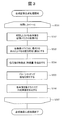
- FIG. 3 is a flowchart for explaining the composite image generation processing in the first embodiment.
- the composite image generation processing is executed by, for example, the image processing unit 216.
- the image processing unit 216 is realized by a program as described above, the operating subject is the CPU 211.
- the composite image generation process will be described with the image processing unit 216 as the operation subject, but it may be understood by replacing it with the CPU 211.
- Step 301 and Step 307 The image processing unit 216 repeatedly executes the processing from step 302 to step 306 for each image acquired by the imaging devices 2241 to 2441 at time t 1 to t n .
- the composite image generation processing for example, when the run until the end of surgery surgery start, surgery start time and t 1, the end of surgery time and tn.
- the imaging devices 2241 to 2441 capture, for example, 30 frames per second, the acquisition time interval of each image is 1/30 seconds.
- the composite image generation process may be executed in units of frames or in units of fields (one field image every 1/60 seconds).
- Step 302 The image processing unit 216 from the image memory (not shown), reads the image acquired by the imaging device 2241 to 2441 at time t k (e.g., three frames or more digital images). In this step, images of three frames or more captured at the same time are acquired.
- the image processing unit 216 calculates the positions of the imaging devices 2241 to 2441 attached to the respective distal end portions of the endoscope arms 22 to 24 in the body of the patient P (for example, in the abdominal cavity and the thoracic cavity). Specifically, the image processing unit 216 determines in advance, for example, information on rotation directions and angles (detected by a position detector) of the joint portions 221 to 223, 231 to 233, and 241 to 243 from a memory (not shown). Information on the lengths between the joints (movable elements) thus obtained and information on the length from a predetermined distal end of the endoscope arm to the nearest joint is obtained.
- the image processing unit 216 identifies each position by calculating the distance and rotation angle of each imaging device from a predetermined reference point (for example, the position of the joint unit 231 is used as a reference).
- the distance and the rotation angle from the reference point of each imaging device located at the distal end of the endoscope arm can be calculated by setting the point as a point and forming a spatial coordinate with this as the origin).
- the image processing unit 216 can also be referred to as a feature point (feature amount) for each image.
- the feature amount is a region around a feature point having a large change in shading that is converted into a feature vector by a pixel value or a differential value. ).
- the image processing unit 216 divides an image to be processed into block units (for example, blocks of 8 pixels ⁇ 8 pixels), and uses a Fourier transform, a discrete cosine transform, or the like to calculate a pixel value of each block. Convert to data in frequency domain. Thereby, the distribution of the frequency component in each block is acquired, and the feature point (feature amount) of each block can be extracted.
- an image in which the edge of each block is emphasized using an edge filter may be used as a feature point (feature amount).
- the image processing unit 216 performs pattern matching processing on each image.
- a pattern matching process (for example, calculating correlations for all pixels and blocks and setting a pixel or block having the highest correlation value as a pattern matching point) may be executed for all regions of each image. You may go in a limited way. In this case, speeding up and efficiency of processing can be achieved.
- When limiting the search range it is possible to determine a search range for blocks or pixels in which the feature amounts of the images match based on the information on the positions of the imaging devices 2241 to 2441 specified in step 303 ( For example, an area of 20% around each image is set as a search range).
- the image processing unit 216 executes pattern matching processing within the search range, and sets a matching position (a position with the highest correlation) in the search area of each image as a pattern matching point.
- Step 306 The image processing unit 216 connects the images at the position recognized as the pattern matching point in step 305 to generate a composite image.
- the pixel values of the images in the overlapping region may be slightly different (for example, there may be a difference in pixel values obtained by imaging even the same object because the imaging directions of the imaging devices are different).
- the images may be joined after removing the overlapping region from one of the images.
- a composite image can be generated by the method as described above, for example, a composite image may be generated using a method disclosed in Japanese Patent Laid-Open No. 10-178564.
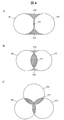
- FIG. 4 schematically shows the field of view of the imaging device, and is a diagram for explaining the reason for providing three or more endoscopes in the present embodiment.
- 4A and 4B show the field of view when two imaging devices are provided, and
- FIG. 4C shows the field of view when three imaging devices are provided.
- the field of view 401 and the field of view 402 of each imaging device should be as small as possible (in the case of FIG. 4A, the overlapping region 405 is small).
- the area of the overlapping region 405 can be reduced, but a blind spot 404 is generated between the visual field 401 and the visual field 402.
- FIG. 4B when the area of the blind spot 404 is reduced, the range that can be covered by the visual field 401 and the visual field 402 is reduced, and the area of the overlapping region 405 is increased.
- a sufficient field of view cannot be obtained for acquiring an image for observing the state of the operation in the patient's body (for example, in the abdominal cavity or the chest cavity) and the state around the organ to be operated.
- three or more imaging devices are provided and three fields of view are used to solve the conflicting problems as described above.
- the area of the overlapping region 405 is reduced, and the blind spot 404 formed by overlapping the two fields of view is eliminated.
- the entire field of view can be formed.
- three or more imaging devices 2241 to 2441 are used.
- the surgical system according to the second embodiment has the same configuration as the surgical system according to the first embodiment. However, in 2nd Embodiment, the structure of the endoscope apparatus 21 in the patient side cart 20 differs.
- a patient-side cart also referred to as a surgical robot
- an endoscope apparatus including an endoscope arm having a function of rotating at least a distal end portion of a cylindrical housing of an endoscope.
- a console device for operating a patient side cart.
- the optical axis of the imaging device forms a predetermined angle with the rotation axis of the distal end portion of the cylindrical housing, and the imaging device rotates the distal end portion of the cylindrical housing of the endoscope.
- a composite image is generated by connecting the acquired images and displayed on the display screen.
- a wide-angle visual field centering on the position of the endoscope can be provided to the surgeon. It is possible to perform an operation while visually confirming the state of the above (endoscopic operation can be realized while ensuring a wide field of view as in open surgery). Also in this case, for example, a foveal lens can be used as the lens of the imaging device.
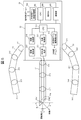
- FIG. 5 is a diagram illustrating a configuration example of the patient cart 20 according to the second embodiment.
- the difference from the first embodiment is that one endoscope arm 27 is attached, and the optical adapter 274 (including the imaging device 2741 and the illumination optical system 2742) at the distal end portion of the endoscope arm 27 is centered on the rotation axis. It is the point comprised so that rotation is possible.
- the distal end surface of the endoscope arm 27 is formed obliquely, and the optical axis of the imaging device 2741 forms a predetermined angle with the rotation axis.
- the angle formed by the optical axis of the imaging device 2741 and the rotation axis can be set to 1 ⁇ 2 of the angle of view (viewing angle) of the lens of the imaging device 2741, for example.
- the inclination angle of the distal end surface of the endoscope arm 27 can also be set to 1 ⁇ 2 of the angle of view of the lens of the imaging device 2741, for example.
- an image during surgery is captured by the imaging device 2741 while the optical adapter 274 at the distal end portion of the endoscope arm 27 is rotated around the rotation axis.
- Control of the rotation of the optical adapter 274 at the distal end portion of the endoscope arm 27 is performed by the endoscope arm drive control unit 214.
- the joint portion 273 is provided with a small (low-speed) actuator for rotating the tip portion different from the actuator for driving the joint, and a rotation drive mechanism (a rotation drive shaft connected to the tip portion and a rotation drive transmission shaft).
- the distal end portion of the endoscope arm 27 can be rotated by various kinds of gears (including, for example, a tip portion and a shaft of a small motor may be connected by a gear such as a bevel gear).
- gears including, for example, a tip portion and a shaft of a small motor may be connected by a gear such as a bevel gear.
- the rotational speed or the like of the distal end portion can be controlled by the endoscope arm drive control unit 214.
- the rotation of the distal end portion of the endoscope arm 27 can be detected by a position detector (for example, an encoder).
- a position detector provided at the joint closest to the tip portion can be used.
- the imaging control unit 215 stores an image captured while the imaging device 2741 rotates together with a time stamp in an image memory (not shown).
- the image processing unit 216 generates a composite image while matching the images acquired by the imaging control unit 215. The composite image generation process will be described later.
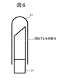
- the distal end portion of the endoscope arm 27 can be covered with a transparent sheath 61 having a rounded end portion, as shown in FIG. Thereby, it can prevent damaging the internal tissue of patient P during an operation.
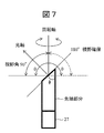
- FIG. 7 is a view for explaining a visual field secured when the distal end portion of the endoscope arm 27 is rotated.
- the viewing angle of the lens of the imaging device is, for example, 90 degrees.
- the angle between the optical axis of the lens and the rotation axis is set to 45 degrees, for example.
- the viewing angle ⁇ that can be secured by the rotation is 180 degrees, which is twice 90 degrees, and a wider field of view can be secured. become able to.
- the angle between the optical axis and the rotation axis is preferably 60 degrees (the inclination angle ⁇ of the tip surface is 30 degrees).
- the viewing angle ⁇ that can be secured by the rotation BR>] is 240 degrees, which is twice 120 degrees.
- the lens is arranged so that the optical axis of the lens having a viewing angle of 180 degrees forms 90 degrees with the rotation axis at the distal end portion of the endoscope arm 27, theoretically, the viewing angle ⁇ of 360 degrees is obtained. Can be secured.
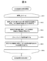
- FIG. 8 is a flowchart for explaining the composite image generation processing in the second embodiment.
- the composite image generation processing is executed by, for example, the image processing unit 216.
- the image processing unit 216 is realized by a program as described above, the operating subject is the CPU 211.
- the composite image generation process will be described with the image processing unit 216 as the operation subject, but it may be understood by replacing it with the CPU 211.
- Step 801 and Step 806 The image processing unit 216 repeatedly executes the processing of Step 802 to Step 805 for each image acquired by the imaging device 2741 at time t 1 to t n .
- the composite image generation processing for example, when the run until the end of surgery surgery start, surgery start time and t 1, the end of surgery time and tn. For example, when the imaging device 2741 captures 30 frames per second, the acquisition time interval of each image is 1/30 second.
- the composite image generation process may be executed in units of frames or in units of fields (one field image every 1/60 seconds).
- Step 802 The image processing unit 216 is acquired from an image memory (not shown) by a composite image generated using images up to time t k (composite image generated in the previous process: previous composite image) and the imaging device 2741. Loaded images. In the case where the composite image at the initial stage of the process start not yet been generated (the case of t 1), the image at time t 1 and time t 2 in place of the composite image is read from the image memory.
- the image processing unit 216 extracts feature points (feature amounts) for the previous composite image and the image at time t k + 1 .
- the image processing unit 216 divides an image to be processed into block units (for example, blocks of 8 pixels ⁇ 8 pixels), and uses a Fourier transform, a discrete cosine transform, or the like to calculate a pixel value of each block. Convert to data in frequency domain. Thereby, the distribution of frequency components in each block is acquired, and the feature amount of each block can be extracted.
- an image in which the edge of each block is emphasized using an edge filter may be used as the feature amount.
- Step 804 The image processing unit 216 performs pattern matching processing on the previous composite image and the image at time t k + 1 .
- pattern matching can be executed in the same way as pattern matching in moving images.
- the image processing unit 216 can calculate, in advance, a search range (a distance that the image moves within one frame time (for example, 1/60 second) from the rotation speed (an image shift range)).
- the search range can be set with a margin that takes into account the range and error), and pattern matching is executed within the search area of each image (the position with the highest correlation). Let it be a point.
- Step 805 The image processing unit 216 generates a new composite image by connecting the previous composite image and the image at time t k + 1 at the position recognized as the pattern matching point in step 804. Note that when the rotation of the distal end portion of the endoscope arm 27 makes one round, a composite image at the viewing angle ⁇ is generated. The images acquired by the second and subsequent rotations are sequentially superimposed on appropriate positions (matched positions) of the already generated composite image.
- a composite image can be generated by the method as described above, for example, a composite image may be generated using a method disclosed in Japanese Patent Laid-Open No. 10-178564.
- ⁇ Low resolution mode and high resolution mode> an image acquired while rotating the distal end portion of the endoscope arm 27 is provided at a low resolution (low image quality: also referred to as the first resolution or the first image quality), and thus obtained by combining them.
- the resultant composite image is also displayed on the display screen of the display device 30 at a low resolution.
- the image acquired by stopping the rotation of the tip portion is displayed on the display screen of the display device 30 with high resolution (high image quality: also referred to as second resolution or second image quality (higher resolution than the first resolution)). Is done.
- the surgeon O operates the console device 10 to instruct to stop the rotation of the distal end portion when he / she wants to find a portion of interest in the composite image and to focus on the portion.
- the portion can be confirmed with a high-resolution image. Since the number of endoscopes to be inserted into the body of the patient P can be reduced as compared with the first embodiment, the endoscope apparatus and the surgery system according to the present embodiment can be made less invasive.
- a surgical system according to the third embodiment has the same configuration as the surgical system according to the first embodiment.
- the structure of the endoscope apparatus 21 in the patient side cart 20 differs.
- the endoscope device 21 is provided with only one endoscope arm 27 whose tip portion rotates.
- the third embodiment includes, for example, three or more endoscopes, and an endoscope including three or more endoscope arms having a function of rotating at least a distal end portion of a cylindrical housing of each endoscope.
- a surgical system including a patient side cart (also referred to as a surgical robot) including a mirror device and a console device for operating the patient side cart.
- the optical axis of each imaging device forms a predetermined angle with the rotation axis of the distal end portion of each cylindrical housing, and while rotating the distal end portion of the cylindrical housing of each endoscope
- a composite image is generated by connecting three or more images acquired by the imaging device and displayed on the display screen.
- an image with a wider field of view (eg, 360 degrees) can be provided to the surgeon. It is possible to perform an operation while visually confirming the state of the position in a wide range (an endoscopic operation can be realized while ensuring a wide field of view like an open abdominal operation). Also in this case, for example, a foveal lens can be used as the lens of the imaging device.
- an image with the rotation stopped is displayed on the display screen.
- an image acquired and displayed in a stopped state can have a higher image quality than an image acquired while rotating.
- the surgeon can visually confirm a desired portion in more detail.
- the surgeon may include information on the position of the target in the body from which the image is acquired in a state where the rotation is stopped. At this time, for example, an image acquired only by an imaging device capable of imaging the target position is displayed on the display screen.
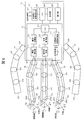
- FIG. 9 is a diagram illustrating a configuration example of the patient cart 20 according to the third embodiment.
- the difference from the first embodiment is that the tip portions of the three or more endoscope arms 27 to 29 rotate in the same manner as in the second embodiment.
- the difference from the second embodiment is that three or more endoscope arms 27 to 29 whose tip portions rotate are provided.
- each optical axis of the imaging devices 2741 to 2941 forms a predetermined angle with the rotation axis of each distal end portion.
- the angle formed by each optical axis of each of the imaging devices 2741 to 2941 and each rotation axis can be set to 1 ⁇ 2 of the angle of view (viewing angle) of each lens of the imaging devices 2741 to 2941, for example.
- the inclination angle of the distal end surfaces of the endoscope arms 27 to 29 can be set to, for example, (90—the viewing angle of the lens of the imaging device 2741 ⁇ 1 ⁇ 2) degrees.
- an image during surgery is captured by the imaging devices 2741 to 2941 while the optical adapters 274 to 294 at the distal end portions of the endoscope arms 27 to 29 are rotated about the rotation axis.
- the rotation control of the optical adapters 274 to 294 at the distal end portions of the endoscope arms 27 to 29 is performed by, for example, the endoscope arm drive control unit 214.
- each of the joint portions 273 to 293 is provided with a small (low-speed) motor for rotating the tip portion different from the motor for driving the joint, and a rotation drive mechanism (a rotation drive shaft coupled to the tip portion and
- the distal end portions of the endoscope arms 27 to 29 are rotated by various types of gears for rotational drive transmission (including, for example, a tip portion and a shaft of a small motor may be connected by a gear such as a bevel gear). it can.
- the rotational speed or the like of the distal end portion can be controlled by the endoscope arm drive control unit 214.
- the rotation of each distal end portion of the endoscope arms 27 to 29 can be detected by a position detector (for example, an encoder).
- each position detector provided at the joint closest to each tip portion can be used.
- the imaging control unit 215 stores an image captured while the imaging devices 2741 to 2941 rotate together with a time stamp in an image memory (not shown).
- the image processing unit 216 generates a composite image while matching the images acquired by the imaging control unit 215. The composite image generation process will be described later.
- the distal end portions of the endoscope arms 27 to 29 can be covered with, for example, a transparent sheath 61 having a rounded distal end portion, as in the second embodiment. It is. Thereby, it can prevent damaging the internal tissue of patient P during an operation.
- the composite image generation process in the third embodiment can be realized by combining the composite image generation process in the first embodiment (FIG. 3) and the composite image generation process in the second embodiment (FIG. 8). Is possible. For example, a composite image of images obtained by imaging while rotating each of the imaging devices 2741 to 2941 of the three or more endoscope arms 27 to 29 is generated according to the process of FIG. Thereby, three or more rotation composite images (also referred to as around view images) are generated. The three or more rotated synthesized images can be further synthesized according to the process of FIG. 3 to generate a final synthesized image.
- an image acquired while rotating the tip portions of the endoscope arms 27 to 29 has a low resolution (low image quality: also referred to as the first resolution or the first image quality). Therefore, a composite image of the rotation image of each tip portion and a final composite image obtained by further joining three or more composite images are also displayed on the display screen of the display device 30 at a low resolution.
- the image acquired by stopping the rotation of the tip portion has a high resolution (high image quality: also referred to as second resolution or second image quality (higher resolution than the first resolution)), as in the second embodiment. Is displayed on the display screen of the display device 30.
- the console device 10 when the operator O wants to find a portion of interest in the final composite image and to focus on it, for example, he / she operates the console device 10 to operate three or more endoscope arms. Instructing the rotation stop of at least one tip portion covering the priority observation portion among the tip portions 27 to 29 and confirming the portion with a high-resolution image by instructing the portion to be focused more closely Can do.
- a composite image representing the current state of the body (for example, intraperitoneal cavity or thoracic cavity) of the patient during surgery is displayed on the display screen of the display device 30.
- past images (regardless of whether or not they are composite images) may be displayed together (for example, on a multi-screen) on the display screen.
- a position where an image of the surgical site can be captured from the point in time when the distal end portions of the endoscope arms 22 to 24 (portion where the imaging device is attached) and the distal end portions of the endoscope arms 27 to 29 are inserted into the patient P
- the image group up to the time point of moving to is held in an image memory (not shown).
- an image around the insertion path of each endoscope arm and an image around the insertion path of the surgical instrument attached to each surgical arm are combined with the image during the current operation.
- the operator O can check whether the surgical instrument operated by the operator O is inserted while excessively compressing the internal organ of the patient P.
- all the tip portions of the three or more endoscope arms may not be configured to be rotatable (at least one of the endoscope arms 22 to 24).
- the distal end portion of the endoscope arm may be configured to be rotatable).
- the functions of the embodiments can also be realized by software program codes.
- a storage medium in which the program code is recorded is provided to the system or apparatus, and the computer (or CPU or MPU) of the system or apparatus reads the program code stored in the storage medium.
- the program code itself read from the storage medium realizes the functions of the above-described embodiment, and the program code itself and the storage medium storing it are included in this embodiment.
- a storage medium for supplying such program code for example, a flexible disk, CD-ROM, DVD-ROM, hard disk, optical disk, magneto-optical disk, CD-R, magnetic tape, nonvolatile memory card, ROM Etc. are used.
- an OS operating system
- the computer CPU or the like performs part or all of the actual processing based on the instruction of the program code.
- the program code of the software that realizes the functions of the embodiment is stored in a storage means such as a hard disk or memory of a system or apparatus or a storage medium such as a CD-RW or CD-R.
- the program code stored in the storage means or the storage medium may be read out and executed by the computer (or CPU or MPU) of the system or apparatus during storage.
Landscapes
- Health & Medical Sciences (AREA)
- Life Sciences & Earth Sciences (AREA)
- Surgery (AREA)
- Engineering & Computer Science (AREA)
- Heart & Thoracic Surgery (AREA)
- Public Health (AREA)
- Nuclear Medicine, Radiotherapy & Molecular Imaging (AREA)
- Veterinary Medicine (AREA)
- General Health & Medical Sciences (AREA)
- Animal Behavior & Ethology (AREA)
- Molecular Biology (AREA)
- Biomedical Technology (AREA)
- Medical Informatics (AREA)
- Pathology (AREA)
- Physics & Mathematics (AREA)
- Radiology & Medical Imaging (AREA)
- Biophysics (AREA)
- Optics & Photonics (AREA)
- Oral & Maxillofacial Surgery (AREA)
- Robotics (AREA)
- Signal Processing (AREA)
- Human Computer Interaction (AREA)
- Endoscopes (AREA)
- Instruments For Viewing The Inside Of Hollow Bodies (AREA)
Abstract
Priority Applications (4)
| Application Number | Priority Date | Filing Date | Title |
|---|---|---|---|
| EP16895438.6A EP3434170B1 (fr) | 2016-03-25 | 2016-03-25 | Endoscope et système d'endoscope comprenant le même |
| JP2018506729A JP6598982B2 (ja) | 2016-03-25 | 2016-03-25 | 内視鏡装置、内視鏡システム、及びそれらを備えた手術システム |
| PCT/JP2016/059672 WO2017163407A1 (fr) | 2016-03-25 | 2016-03-25 | Dispositif endoscope, système endoscope, et système de chirurgie associé |
| US16/129,326 US20190008367A1 (en) | 2016-03-25 | 2018-09-12 | Endoscope apparatus, endoscope system and surgical system including the same |
Applications Claiming Priority (1)
| Application Number | Priority Date | Filing Date | Title |
|---|---|---|---|
| PCT/JP2016/059672 WO2017163407A1 (fr) | 2016-03-25 | 2016-03-25 | Dispositif endoscope, système endoscope, et système de chirurgie associé |
Related Child Applications (1)
| Application Number | Title | Priority Date | Filing Date |
|---|---|---|---|
| US16/129,326 Continuation US20190008367A1 (en) | 2016-03-25 | 2018-09-12 | Endoscope apparatus, endoscope system and surgical system including the same |
Publications (1)
| Publication Number | Publication Date |
|---|---|
| WO2017163407A1 true WO2017163407A1 (fr) | 2017-09-28 |
Family
ID=59900080
Family Applications (1)
| Application Number | Title | Priority Date | Filing Date |
|---|---|---|---|
| PCT/JP2016/059672 Ceased WO2017163407A1 (fr) | 2016-03-25 | 2016-03-25 | Dispositif endoscope, système endoscope, et système de chirurgie associé |
Country Status (4)
| Country | Link |
|---|---|
| US (1) | US20190008367A1 (fr) |
| EP (1) | EP3434170B1 (fr) |
| JP (1) | JP6598982B2 (fr) |
| WO (1) | WO2017163407A1 (fr) |
Cited By (5)
| Publication number | Priority date | Publication date | Assignee | Title |
|---|---|---|---|---|
| CN109330692A (zh) * | 2018-07-31 | 2019-02-15 | 深圳市精锋医疗科技有限公司 | 视野较好的从操作设备组件及手术机器人 |
| CN111278344A (zh) * | 2017-11-01 | 2020-06-12 | 索尼公司 | 手术臂系统和手术臂控制系统 |
| WO2021152754A1 (fr) * | 2020-01-29 | 2021-08-05 | オリンパス株式会社 | Dispositif de traitement d'image, système d'observation et procédé d'observation |
| WO2022092026A1 (fr) * | 2020-10-29 | 2022-05-05 | 国立大学法人東海国立大学機構 | Outil d'assistance chirurgicale et système d'assistance chirurgicale |
| WO2025046896A1 (fr) * | 2023-08-31 | 2025-03-06 | オリンパスメディカルシステムズ株式会社 | Dispositif endoscopique, dispositif de traitement d'image, système en hôpital, procédé de traitement d'image et programme de traitement d'image |
Families Citing this family (11)
| Publication number | Priority date | Publication date | Assignee | Title |
|---|---|---|---|---|
| CN110833379A (zh) * | 2018-08-19 | 2020-02-25 | 广州迪克医疗器械有限公司 | 多平面睡眠监测内镜 |
| JP7247702B2 (ja) * | 2019-03-27 | 2023-03-29 | ソニーグループ株式会社 | 内視鏡システム、内視鏡制御方法、及び、撮像制御装置 |
| US11278361B2 (en) | 2019-05-21 | 2022-03-22 | Verb Surgical Inc. | Sensors for touch-free control of surgical robotic systems |
| US11504193B2 (en) * | 2019-05-21 | 2022-11-22 | Verb Surgical Inc. | Proximity sensors for surgical robotic arm manipulation |
| US12396632B2 (en) * | 2019-09-23 | 2025-08-26 | John Schelter | Enhanced visualization methods and systems for endoscopic procedures |
| US20230017411A1 (en) * | 2021-07-14 | 2023-01-19 | Cilag Gmbh International | Endoscope with source and pixel level image modulation for multispectral imaging |
| US12376910B2 (en) | 2021-09-29 | 2025-08-05 | Cilag Gmbh International | Methods for controlling cooperative surgical instruments |
| US20230255442A1 (en) * | 2022-02-11 | 2023-08-17 | Canon U.S.A., Inc. | Continuum robot apparatuses, methods, and storage mediums |
| CN115005754A (zh) * | 2022-06-28 | 2022-09-06 | 卓外(上海)医疗电子科技有限公司 | 全视野超微创多路腹腔镜成像装置 |
| CN115956859B (zh) | 2022-10-11 | 2026-04-14 | 中国医学科学院北京协和医院 | 内窥镜控制方法及手术机器人系统 |
| US20240341580A1 (en) * | 2023-04-14 | 2024-10-17 | Cilag Gmbh International | External triggering of an illumination source with a multiple tool endoscopic visualization system |
Citations (8)
| Publication number | Priority date | Publication date | Assignee | Title |
|---|---|---|---|---|
| JPH07327921A (ja) * | 1994-06-14 | 1995-12-19 | Olympus Optical Co Ltd | 医療用撮像装置 |
| JPH08332169A (ja) * | 1995-06-08 | 1996-12-17 | Olympus Optical Co Ltd | 体腔内観察装置 |
| JPH1043127A (ja) * | 1996-08-02 | 1998-02-17 | Tsunehisa Shimoda | 医療用内視鏡 |
| JPH11113836A (ja) * | 1997-10-20 | 1999-04-27 | Olympus Optical Co Ltd | 内視鏡装置 |
| JP2004289225A (ja) * | 2003-03-19 | 2004-10-14 | Minolta Co Ltd | 撮像装置 |
| JP2006288869A (ja) * | 2005-04-13 | 2006-10-26 | Hitachi Medical Corp | 内視鏡画像表示装置 |
| JP2008528130A (ja) * | 2005-01-24 | 2008-07-31 | インテュイティブ サージカル, インコーポレイテッド | ロボット手術のためのモジュールマニピュレーター支持体 |
| WO2010050243A1 (fr) * | 2008-10-31 | 2010-05-06 | 合同会社ジャパン・メディカル・クリエーティブ | Dispositif chirurgical |
Family Cites Families (3)
| Publication number | Priority date | Publication date | Assignee | Title |
|---|---|---|---|---|
| DE102012025100A1 (de) * | 2012-12-20 | 2014-06-26 | avateramedical GmBH | Entkoppeltes Mehrkamerasystem für die minimal-invasive Chirurgie |
| US20150045619A1 (en) * | 2013-08-09 | 2015-02-12 | Chang Bing Show Chwan Memorial Hospital | System and method for mosaicing endoscope images using wide angle view endoscope |
| WO2015191784A1 (fr) * | 2014-06-10 | 2015-12-17 | Nitesh Ratnakar | Endoscope doté de multiples vues et nouvelles configurations adaptées a celui-ci |
-
2016
- 2016-03-25 WO PCT/JP2016/059672 patent/WO2017163407A1/fr not_active Ceased
- 2016-03-25 JP JP2018506729A patent/JP6598982B2/ja active Active
- 2016-03-25 EP EP16895438.6A patent/EP3434170B1/fr active Active
-
2018
- 2018-09-12 US US16/129,326 patent/US20190008367A1/en not_active Abandoned
Patent Citations (8)
| Publication number | Priority date | Publication date | Assignee | Title |
|---|---|---|---|---|
| JPH07327921A (ja) * | 1994-06-14 | 1995-12-19 | Olympus Optical Co Ltd | 医療用撮像装置 |
| JPH08332169A (ja) * | 1995-06-08 | 1996-12-17 | Olympus Optical Co Ltd | 体腔内観察装置 |
| JPH1043127A (ja) * | 1996-08-02 | 1998-02-17 | Tsunehisa Shimoda | 医療用内視鏡 |
| JPH11113836A (ja) * | 1997-10-20 | 1999-04-27 | Olympus Optical Co Ltd | 内視鏡装置 |
| JP2004289225A (ja) * | 2003-03-19 | 2004-10-14 | Minolta Co Ltd | 撮像装置 |
| JP2008528130A (ja) * | 2005-01-24 | 2008-07-31 | インテュイティブ サージカル, インコーポレイテッド | ロボット手術のためのモジュールマニピュレーター支持体 |
| JP2006288869A (ja) * | 2005-04-13 | 2006-10-26 | Hitachi Medical Corp | 内視鏡画像表示装置 |
| WO2010050243A1 (fr) * | 2008-10-31 | 2010-05-06 | 合同会社ジャパン・メディカル・クリエーティブ | Dispositif chirurgical |
Non-Patent Citations (1)
| Title |
|---|
| See also references of EP3434170A4 * |
Cited By (12)
| Publication number | Priority date | Publication date | Assignee | Title |
|---|---|---|---|---|
| CN111278344A (zh) * | 2017-11-01 | 2020-06-12 | 索尼公司 | 手术臂系统和手术臂控制系统 |
| EP3705018A4 (fr) * | 2017-11-01 | 2020-10-14 | Sony Corporation | Système de bras chirurgical et système de commande de bras chirurgical |
| JPWO2019087904A1 (ja) * | 2017-11-01 | 2020-12-10 | ソニー株式会社 | 手術アームシステム及び手術アーム制御システム |
| JP7115493B2 (ja) | 2017-11-01 | 2022-08-09 | ソニーグループ株式会社 | 手術アームシステム及び手術アーム制御システム |
| US11612306B2 (en) | 2017-11-01 | 2023-03-28 | Sony Corporation | Surgical arm system and surgical arm control system |
| CN111278344B (zh) * | 2017-11-01 | 2023-09-05 | 索尼公司 | 手术臂系统和手术臂控制系统 |
| CN109330692A (zh) * | 2018-07-31 | 2019-02-15 | 深圳市精锋医疗科技有限公司 | 视野较好的从操作设备组件及手术机器人 |
| CN109330692B (zh) * | 2018-07-31 | 2023-08-22 | 深圳市精锋医疗科技股份有限公司 | 视野较好的从操作设备组件及手术机器人 |
| WO2021152754A1 (fr) * | 2020-01-29 | 2021-08-05 | オリンパス株式会社 | Dispositif de traitement d'image, système d'observation et procédé d'observation |
| US12212880B2 (en) | 2020-01-29 | 2025-01-28 | Olympus Corporation | Image processing apparatus, observation system, and observation method |
| WO2022092026A1 (fr) * | 2020-10-29 | 2022-05-05 | 国立大学法人東海国立大学機構 | Outil d'assistance chirurgicale et système d'assistance chirurgicale |
| WO2025046896A1 (fr) * | 2023-08-31 | 2025-03-06 | オリンパスメディカルシステムズ株式会社 | Dispositif endoscopique, dispositif de traitement d'image, système en hôpital, procédé de traitement d'image et programme de traitement d'image |
Also Published As
| Publication number | Publication date |
|---|---|
| EP3434170A1 (fr) | 2019-01-30 |
| EP3434170A4 (fr) | 2019-11-20 |
| JPWO2017163407A1 (ja) | 2019-02-14 |
| JP6598982B2 (ja) | 2019-10-30 |
| EP3434170B1 (fr) | 2021-03-17 |
| US20190008367A1 (en) | 2019-01-10 |
Similar Documents
| Publication | Publication Date | Title |
|---|---|---|
| JP6598982B2 (ja) | 内視鏡装置、内視鏡システム、及びそれらを備えた手術システム | |
| JP6982605B2 (ja) | 外科用器具可視性のロボット制御 | |
| JP7480477B2 (ja) | 医療用観察システム、制御装置及び制御方法 | |
| CN112384339B (zh) | 用于主机/工具配准和控制以进行直观运动的系统和方法 | |
| JP6389467B2 (ja) | 低侵襲手術のための分離されたマルチカメラシステム | |
| JP7115493B2 (ja) | 手術アームシステム及び手術アーム制御システム | |
| JP3506809B2 (ja) | 体腔内観察装置 | |
| JP7151109B2 (ja) | 医療用撮像装置及び医療用観察システム | |
| JP2023544360A (ja) | 複数の外科用ディスプレイ上へのインタラクティブ情報オーバーレイ | |
| EP2615993B1 (fr) | Contrôle robotique utilisant des image du reseau de vaisseaux sanguins | |
| JP2023544594A (ja) | 容量及びユーザ操作に基づく階層化されたシステムの表示制御 | |
| JPWO2018159328A1 (ja) | 医療用アームシステム、制御装置及び制御方法 | |
| WO2019116592A1 (fr) | Dispositif pour ajuster une image d'affichage d'endoscope, et système de chirurgie | |
| US11540700B2 (en) | Medical supporting arm and medical system | |
| JP7334499B2 (ja) | 手術支援システム、制御装置及び制御方法 | |
| WO2017145475A1 (fr) | Dispositif de traitement d'informations pour utilisation médicale, procédé de traitement d'informations, système de traitement d'informations pour utilisation médicale | |
| JPWO2020054566A1 (ja) | 医療用観察システム、医療用観察装置及び医療用観察方法 | |
| CN108348134A (zh) | 内窥镜系统 | |
| JP2023507063A (ja) | 手術中に画像取込装置を制御するための方法、装置、およびシステム | |
| JP4027876B2 (ja) | 体腔内観察システム | |
| CN115720505A (zh) | 医疗系统、信息处理装置和信息处理方法 | |
| JPH08336497A (ja) | 体腔内観察装置 | |
| WO2017082047A1 (fr) | Système d'endoscope | |
| WO2019155931A1 (fr) | Système chirurgical, dispositif de traitement d'image, et méthode de traitement d'image | |
| CN114340469B (zh) | 医疗支撑臂和医疗系统 |
Legal Events
| Date | Code | Title | Description |
|---|---|---|---|
| WWE | Wipo information: entry into national phase |
Ref document number: 2018506729 Country of ref document: JP |
|
| NENP | Non-entry into the national phase |
Ref country code: DE |
|
| WWE | Wipo information: entry into national phase |
Ref document number: 2016895438 Country of ref document: EP |
|
| ENP | Entry into the national phase |
Ref document number: 2016895438 Country of ref document: EP Effective date: 20181025 |
|
| 121 | Ep: the epo has been informed by wipo that ep was designated in this application |
Ref document number: 16895438 Country of ref document: EP Kind code of ref document: A1 |