WO2017170242A1 - Dispositif de fabrication de tissu non tissé et procédé de fabrication de tissu non tissé - Google Patents
Dispositif de fabrication de tissu non tissé et procédé de fabrication de tissu non tissé Download PDFInfo
- Publication number
- WO2017170242A1 WO2017170242A1 PCT/JP2017/012063 JP2017012063W WO2017170242A1 WO 2017170242 A1 WO2017170242 A1 WO 2017170242A1 JP 2017012063 W JP2017012063 W JP 2017012063W WO 2017170242 A1 WO2017170242 A1 WO 2017170242A1
- Authority
- WO
- WIPO (PCT)
- Prior art keywords
- shaft
- diffusion
- shaft portion
- machine direction
- outlet side
- Prior art date
- Legal status (The legal status is an assumption and is not a legal conclusion. Google has not performed a legal analysis and makes no representation as to the accuracy of the status listed.)
- Ceased
Links
Images


Classifications
-
- D—TEXTILES; PAPER
- D01—NATURAL OR MAN-MADE THREADS OR FIBRES; SPINNING
- D01D—MECHANICAL METHODS OR APPARATUS IN THE MANUFACTURE OF ARTIFICIAL FILAMENTS, THREADS, FIBRES, BRISTLES OR RIBBONS
- D01D5/00—Formation of filaments, threads, or the like
- D01D5/08—Melt spinning methods
- D01D5/088—Cooling filaments, threads or the like, leaving the spinnerettes
-
- D—TEXTILES; PAPER
- D04—BRAIDING; LACE-MAKING; KNITTING; TRIMMINGS; NON-WOVEN FABRICS
- D04H—MAKING TEXTILE FABRICS, e.g. FROM FIBRES OR FILAMENTARY MATERIAL; FABRICS MADE BY SUCH PROCESSES OR APPARATUS, e.g. FELTS, NON-WOVEN FABRICS; COTTON-WOOL; WADDING ; NON-WOVEN FABRICS FROM STAPLE FIBRES, FILAMENTS OR YARNS, BONDED WITH AT LEAST ONE WEB-LIKE MATERIAL DURING THEIR CONSOLIDATION
- D04H1/00—Non-woven fabrics formed wholly or mainly of staple fibres or like relatively short fibres
- D04H1/70—Non-woven fabrics formed wholly or mainly of staple fibres or like relatively short fibres characterised by the method of forming fleeces or layers, e.g. reorientation of fibres
- D04H1/72—Non-woven fabrics formed wholly or mainly of staple fibres or like relatively short fibres characterised by the method of forming fleeces or layers, e.g. reorientation of fibres the fibres being randomly arranged
- D04H1/736—Non-woven fabrics formed wholly or mainly of staple fibres or like relatively short fibres characterised by the method of forming fleeces or layers, e.g. reorientation of fibres the fibres being randomly arranged characterised by the apparatus for arranging fibres
-
- D—TEXTILES; PAPER
- D04—BRAIDING; LACE-MAKING; KNITTING; TRIMMINGS; NON-WOVEN FABRICS
- D04H—MAKING TEXTILE FABRICS, e.g. FROM FIBRES OR FILAMENTARY MATERIAL; FABRICS MADE BY SUCH PROCESSES OR APPARATUS, e.g. FELTS, NON-WOVEN FABRICS; COTTON-WOOL; WADDING ; NON-WOVEN FABRICS FROM STAPLE FIBRES, FILAMENTS OR YARNS, BONDED WITH AT LEAST ONE WEB-LIKE MATERIAL DURING THEIR CONSOLIDATION
- D04H3/00—Non-woven fabrics formed wholly or mainly of yarns or like filamentary material of substantial length
- D04H3/08—Non-woven fabrics formed wholly or mainly of yarns or like filamentary material of substantial length characterised by the method of strengthening or consolidating
- D04H3/16—Non-woven fabrics formed wholly or mainly of yarns or like filamentary material of substantial length characterised by the method of strengthening or consolidating with bonds between thermoplastic filaments produced in association with filament formation, e.g. immediately following extrusion
-
- D—TEXTILES; PAPER
- D01—NATURAL OR MAN-MADE THREADS OR FIBRES; SPINNING
- D01D—MECHANICAL METHODS OR APPARATUS IN THE MANUFACTURE OF ARTIFICIAL FILAMENTS, THREADS, FIBRES, BRISTLES OR RIBBONS
- D01D5/00—Formation of filaments, threads, or the like
- D01D5/08—Melt spinning methods
-
- D—TEXTILES; PAPER
- D01—NATURAL OR MAN-MADE THREADS OR FIBRES; SPINNING
- D01D—MECHANICAL METHODS OR APPARATUS IN THE MANUFACTURE OF ARTIFICIAL FILAMENTS, THREADS, FIBRES, BRISTLES OR RIBBONS
- D01D5/00—Formation of filaments, threads, or the like
- D01D5/08—Melt spinning methods
- D01D5/088—Cooling filaments, threads or the like, leaving the spinnerettes
- D01D5/092—Cooling filaments, threads or the like, leaving the spinnerettes in shafts or chimneys
-
- D—TEXTILES; PAPER
- D01—NATURAL OR MAN-MADE THREADS OR FIBRES; SPINNING
- D01D—MECHANICAL METHODS OR APPARATUS IN THE MANUFACTURE OF ARTIFICIAL FILAMENTS, THREADS, FIBRES, BRISTLES OR RIBBONS
- D01D5/00—Formation of filaments, threads, or the like
- D01D5/08—Melt spinning methods
- D01D5/098—Melt spinning methods with simultaneous stretching
- D01D5/0985—Melt spinning methods with simultaneous stretching by means of a flowing gas (e.g. melt-blowing)
-
- D—TEXTILES; PAPER
- D04—BRAIDING; LACE-MAKING; KNITTING; TRIMMINGS; NON-WOVEN FABRICS
- D04H—MAKING TEXTILE FABRICS, e.g. FROM FIBRES OR FILAMENTARY MATERIAL; FABRICS MADE BY SUCH PROCESSES OR APPARATUS, e.g. FELTS, NON-WOVEN FABRICS; COTTON-WOOL; WADDING ; NON-WOVEN FABRICS FROM STAPLE FIBRES, FILAMENTS OR YARNS, BONDED WITH AT LEAST ONE WEB-LIKE MATERIAL DURING THEIR CONSOLIDATION
- D04H1/00—Non-woven fabrics formed wholly or mainly of staple fibres or like relatively short fibres
- D04H1/70—Non-woven fabrics formed wholly or mainly of staple fibres or like relatively short fibres characterised by the method of forming fleeces or layers, e.g. reorientation of fibres
- D04H1/72—Non-woven fabrics formed wholly or mainly of staple fibres or like relatively short fibres characterised by the method of forming fleeces or layers, e.g. reorientation of fibres the fibres being randomly arranged
- D04H1/732—Non-woven fabrics formed wholly or mainly of staple fibres or like relatively short fibres characterised by the method of forming fleeces or layers, e.g. reorientation of fibres the fibres being randomly arranged by fluid current, e.g. air-lay
-
- D—TEXTILES; PAPER
- D01—NATURAL OR MAN-MADE THREADS OR FIBRES; SPINNING
- D01D—MECHANICAL METHODS OR APPARATUS IN THE MANUFACTURE OF ARTIFICIAL FILAMENTS, THREADS, FIBRES, BRISTLES OR RIBBONS
- D01D7/00—Collecting the newly-spun products
Definitions
- This disclosure relates to a nonwoven fabric manufacturing apparatus and a nonwoven fabric manufacturing method.
- Non-woven fabrics such as spunbonded non-woven fabrics are widely used for medical, hygiene materials, civil engineering materials and packaging materials.
- Spunbond nonwoven fabric is collected and deposited while being diffused on the collection medium after the cooling treatment using the cooling air and the drawing treatment using the drawing air are performed on the filaments obtained by melt spinning the thermoplastic resin. It is manufactured from the web obtained.
- Japanese Patent No. 2556953 the horizontal cross-section is rectangular, the cooling chamber is gradually reduced in cross-section in the filament running direction, and the stepped recess is formed in the wall at the discharge port connected to the cooling chamber.
- an apparatus for producing a spun fiber strip from aerodynamically stretched synthetic resin filaments which has a stretching nozzle and a fiber placement device connected to the stretching nozzle.
- the fiber placement device of Japanese Patent No. 2556953 has a rectangular cross section in the horizontal direction, has a venturi-shaped basin in the vertical direction, and a jet pump in the form of a diffuser outlet. The amount of air sucked from the free air suction port is adjusted by an intake pipe opposed to the diffuser outlet with the filter belt interposed therebetween.
- Japanese Patent No. 3135498 has a nozzle plate having a number of nozzles, a processing shaft, a transport unit, and a transport conveyor. Process air flows into the processing shaft and the transport unit, and endless fibers are discharged from the nozzle holes of the nozzle plate. As the endless fiber group in the form of a mixture of air and fibers flows in and flows into the processing shaft by the discharge movement toward the transport conveyor, the transport unit goes to the central inflow conduit for the endless fiber group and then to the transport conveyor A spin fleece web is manufactured from endless thermoplastic resin fibers having an elongated diffuser conduit and forced forcing movement and overlapping fleece formation, both of which extend in a direction transverse to the direction of travel of the conveyor belt An apparatus is disclosed. In US Pat. No.
- inlet conduits and / or diffuser conduits are used for air and fiber mixing and flow for additional introduction of air into a conduit extending across the width of the conduit across the direction of travel of the conveyor belt.
- An aerodynamic equalizing device in the form of a slit and in the form of an outflow slit for releasing air from the conduit is additionally provided, and the flow rate to be additionally fed and the flow rate of the air to be discharged It is controlled or adjusted for the purpose of affecting the equal distribution of fibers during mixing.
- Japanese Patent No. 3135498 discloses that the inner surface of the inflow conduit and / or the diffuser conduit has an obstruction member in the vicinity of the surface in the longitudinal section of the conduit, and a spiral region is formed in the rear in the flow direction. .
- a spinneret for forming a filament is provided, and there is a cooling chamber supplied with processing air for cooling the filament downstream of the spinneret, and a drawing unit for drawing the filament is connected to the cooling chamber.
- the connecting region between the cooling chamber and the stretching unit is closed, the stretching unit has a stretching passage in which the passage wall is branched over at least a part of the length of the stretching passage;
- additional air is formed from the filaments, which are injected into the drawing passages under the condition that the filament bundles are formed widely in the machine direction and provided with a deposition device for depositing the filaments of the spunbond web.
- the deposition unit downstream of the stretching unit, the deposition unit is composed of an upstream diffuser and an adjacent downstream diffuser, and an ambient air inlet slit is provided between the upstream diffuser and the downstream diffuser. is there.
- Japanese Patent No. 3135498 aims to obtain a nonwoven fabric having a uniform mesh size.
- a nonwoven fabric with high uniformity may have insufficient filament entanglement and lower strength.
- the present disclosure has been made in view of the above-described facts, and an object of the present disclosure is to provide a nonwoven fabric manufacturing apparatus and a nonwoven fabric manufacturing method in which a nonwoven fabric with improved strength can be obtained while suppressing the loss of uniformity.
- the nonwoven fabric manufacturing apparatus of the present disclosure is disposed on the upper side of the shaft and includes a slit-shaped air guide path, and the filaments together with air flow from the inlet side to the outlet side of the air guide path.
- the first shaft portion to be supplied disposed on the lower side of the shaft, the inlet side communicates with the outlet side of the first shaft portion, and the outlet side is disposed opposite to the collecting portion for collecting the filament,
- a second shaft portion whose opening width along the machine direction on the inlet side is wider than an opening width along the machine direction of the first shaft portion; an outlet side of the first shaft portion; and an inlet side of the second shaft portion
- a diffusion shaft configured to include a step portion connecting the outlet side of the first shaft portion and the inlet side of the second shaft portion.
- the manufacturing method of the nonwoven fabric of the present disclosure includes a first shaft portion that is disposed on the shaft upper side and includes a slit-shaped air guide path, and filaments are supplied together with air from the inlet side to the outlet side of the air guide path.
- the inlet side communicates with the outlet side of the first shaft portion, and the outlet side is arranged to face the collecting portion for collecting the filament, and the opening on the inlet side along the machine direction
- a width is provided at a connection portion between the second shaft portion widened from the opening width along the machine direction of the first shaft portion, and the outlet side of the first shaft portion and the inlet side of the second shaft portion,
- a diffusion shaft having a stepped portion connecting the outlet side of the first shaft portion and the inlet side of the second shaft portion, supplying a filament together with air from the inlet side of the first shaft portion, the second The filaments ejected from the outlet side of the Yafuto portion was collected deposited in the collection unit, generates
- Nonwoven fabric manufacturing apparatus and manufacturing method include a spinning unit that spins a plurality of filaments from a molten resin obtained by melting a thermoplastic resin, a cooling unit that cools the spun filaments, and a plurality of filaments
- a web is produced by collecting and depositing at the collection section while diffusing a plurality of stretched filaments.
- a diffusion shaft is provided between the extending part and the collection part, and the air passing through the diffusion shaft (spouting air) is diffused in the machine direction, and is ejected from the opening on the lower side of the diffusion shaft to the collection part. Thus, a highly uniform web is generated.
- the diffusion shaft includes a first shaft portion and a second shaft portion.
- the opening width along the machine direction on the inlet side is wider than the opening width along the machine direction on the outlet side of the first shaft portion.
- the outlet side of the first shaft portion and the inlet side of the second shaft portion are connected by a step portion.
- the blown air introduced from the first shaft portion to the second shaft portion passes through the step portion, thereby generating a region in which the speed fluctuation is promoted and the speed fluctuation increases.
- entanglement between the filaments is promoted by generating a region where the velocity fluctuation of the blown air is large.
- a web with increased filament entanglement is obtained, and the nonwoven fabric produced from this web has improved filament strength due to increased filament entanglement.
- the step portion provided on the diffusion shaft may have a shape that can promote the fluctuation of the speed of the blown air in the second shaft portion by widening the opening width along the machine direction between the first shaft portion and the second shaft portion. What is necessary is just to provide in the at least one side of the direction opposite to a machine direction side and a machine direction.
- the stepped portion may be provided continuously along the machine width direction on each of the machine direction side and the direction opposite to the machine direction.
- the stepped portion includes a first stepped portion provided on the machine direction side and a second stepped portion provided on the side opposite to the machine direction along the machine width direction. They may be arranged alternately.
- the second shaft portion may be formed such that the opening width along the machine direction gradually increases from the inlet side toward the outlet side.
- the present disclosure it is possible to promote the occurrence of entanglement in the filament conveyed through the diffusion shaft by the air that becomes the blown air, so that a nonwoven fabric having improved strength due to the entanglement of the filament can be obtained. There is an effect that. Therefore, according to the present disclosure, it is possible to provide a non-woven fabric manufacturing apparatus and a non-woven fabric manufacturing method capable of obtaining a non-woven fabric with improved strength while suppressing the loss of uniformity.
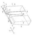
- FIG. 1 the principal part of the manufacturing apparatus 10 of the nonwoven fabric which concerns on this Embodiment is shown.
- the manufacturing apparatus 10 according to the present embodiment is used for manufacturing a spunbonded nonwoven fabric.
- the MD (machine direction) direction indicates the machine direction
- the CD (cross-machine direction) direction indicates the width direction (machine width direction) intersecting the MD direction
- the UP direction is the vertical direction. Is shown above.
- the production apparatus 10 includes a spinning unit 12 that generates a filament by spinning a molten resin in which a thermoplastic resin used for a spunbond nonwoven fabric is melted, a cooling unit 14 that performs a cooling process on the filament, and a filament that is stretched. The extending
- the manufacturing apparatus 10 also includes a collection unit 18 that collects the filaments that have been cooled and stretched to obtain a web that becomes a nonwoven fabric, and a diffusion unit 20 that ejects the filaments toward the collection unit 18.
- the spinning unit 12 includes a spinneret 22 in which a plurality of spinning nozzles are arranged, and a molten resin introduction tube 24 is connected to the spinneret 22.
- the molten resin is introduced from the molten resin introduction pipe 24 into the spinneret 22, thereby spinning the filament from a plurality of spinning nozzles.
- the spinning unit 12 derives a plurality of filaments arranged in the CD direction.
- the cooling unit 14 includes a cooling chamber 26 into which a plurality of spun filaments are introduced, and a cooling air supply duct 28 is connected to the cooling chamber 26. The cooling unit 14 cools the plurality of filaments introduced into the cooling chamber 26 with the cooling air supplied from the cooling air supply duct 28.
- the extending section 16 includes an extending shaft 30 that has an opening cross section that is long in the CD direction (in FIG. 1, the front and back directions in the drawing) and short in the MD direction and extends in the vertical direction.
- a plurality of filaments are introduced from the cooling section 14 into the stretching shaft 30 of the stretching section 16.
- the drawing unit 16 uses the cooling air introduced together with the plurality of filaments or the air wind supplied into the drawing shaft 30 separately from the cooling air as the drawing air, and draws the filament introduced from the cooling unit 14 while drawing it.
- the collecting unit 18 includes a moving band 32 as a collecting medium formed by mesh or punching metal, and suction means (not shown) provided below the moving band 32.
- the diffusion unit 20 includes a diffusion shaft 36. In the diffusion shaft 36, the upper opening is directed to the opening on the lower end side of the extending shaft 30 of the extending portion 16, and the lower opening is directed to the collecting surface 32 ⁇ / b> A of the moving band 32 of the collecting portion 18. ing.
- a plurality of cooled and drawn filaments are introduced into the diffusion shaft 36 from the drawing shaft 30.
- the diffusion unit 20 uses a plurality of filaments and a drawing air introduced from the drawing shaft 30 to the diffusion shaft 36 together with a plurality of filaments or an air wind introduced to the diffusion shaft 36 separately from the drawing air, and conveys the plurality of filaments by the blowing air. Then, the filament is ejected from the opening on the lower side of the diffusion shaft 36 toward the collection surface 32 ⁇ / b> A of the moving band 32.
- the collection unit 18 collects the filaments ejected on the collection surface 32A of the moving zone 32 on the collection surface 32A while sucking the filament by the suction means, and generates a web that becomes a nonwoven fabric.
- a slit-like air guide path is formed in the diffusion shaft 36.
- the air guide path of the diffusion shaft 36 is formed such that the internal opening width (opening width along the MD direction) expands downward, and the blown air passing through the diffusion shaft 36 expands along the MD direction (diffusion). )
- the plurality of filaments are diffused when passing through the diffusion shaft 36 of the diffusion unit 20, and are ejected and deposited on the collection surface 32 ⁇ / b> A of the collection unit 18.
- the distance between the lower end of the diffusion shaft 36 and the collection surface 32 ⁇ / b> A of the moving band 32 is in the range from several tens mm to one hundred mm, and the filament is more than necessary after being ejected from the diffusion shaft 36. To prevent it from diffusing.
- the manufacturing apparatus 10 can apply a known configuration in which a molten resin is spun to generate a plurality of filaments, and the generated plurality of filaments are collected by cooling and stretching.
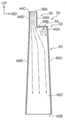
- the diffusion shaft 36 includes an upper shaft 38 as a first shaft portion and a lower shaft 40 as a second shaft portion. Further, the diffusion shaft 36 is provided with a step portion 42 at a connection portion between the upper shaft 38 and the lower shaft 40. In the diffusion shaft 36, the length along the vertical direction of the lower shaft 40 is longer than that of the upper shaft 38, and the stepped portion 42 is formed above the intermediate portion in the vertical direction of the diffusion shaft 36. Yes.
- the upper shaft 38 has a wall portion 44A and a wall portion 44B arranged in pairs along the MD direction, and a pair of side wall portions 44C arranged in the CD direction.
- the upper shaft 38 is formed into a long rectangular cylindrical shape in which the opening cross section of the upper end opening 38A and the lower end opening 38B is narrow in the MD direction and long in the CD direction by the wall portions 44A and 44B and the pair of side wall portions 44C. Has been.
- the upper shaft 38 has an opening width (opening width along the MD direction) and an opening length (opening length along the CD direction) of the upper opening 38A. 1), a plurality of filaments led out from the stretched shaft 30 are introduced.
- the upper shaft 38 may have the wall portions 44A and 44B parallel to each other, or may be slightly inclined so that the opening width gradually increases from the opening 38A toward the opening 38B.
- the walls 44A and 44B are inclined so that the opening width gradually increases from the opening 38A toward the opening 38B, whereby the upper shaft 38 has the opening width of the lower end opening 38B. It is slightly larger than the opening width of the upper opening 38A.
- the lower shaft 40 has a wall portion 46A and a wall portion 46B arranged in pairs along the MD direction, and a pair of side wall portions 46C in the CD direction (only one is shown in FIG. 2). ) Is arranged.
- the lower shaft 40 is formed into a long rectangular cylindrical shape in which the opening cross section of the upper end opening 40A and the lower end opening 40B is narrow in the MD direction and long in the CD direction by the wall portions 46A and 46B and the pair of side wall portions 46C. Has been.
- the lower shaft 40 has an upper end opening 40 ⁇ / b> A facing the opening 38 ⁇ / b> B of the upper shaft 38, and a lower end opening 40 ⁇ / b> B facing the moving band 32 of the collection unit 18.
- the lower shaft 40 has the wall portions 46A and 46B inclined so that the opening width gradually increases from the openings 40A to 40B.
- the lower shaft 40 has an opening width gradually increased from the upper end opening 40A toward the lower end opening 40B, and the lower end opening 40B has an opening width larger than the upper end opening 40A.
- the lower shaft 40 does not have to have an opening width that is at least narrow from the upper end opening 40A toward the lower end opening 40B.
- the lower shaft 40 has an opening width that changes from the upper end opening 40A toward the lower end opening 40B. The structure which does not do may be sufficient.
- the opening width Wd of the upper end opening 40A of the lower shaft 40 is larger than the opening width Wu of the lower end opening 38B of the upper shaft 38 (Wu ⁇ Wd).
- the stepped portion 42 is provided with connecting wall portions 48A and 48B, and each of the connecting wall portions 48A and 48B is along a direction (horizontal direction) intersecting the vertical direction. Are arranged.
- the lower end of the side wall portion 44C of the upper shaft 38 and the upper end of the side wall portion 46C of the lower shaft 40 are integrally connected.
- the lower end portion of the wall portion 44A on the MD direction side of the upper shaft 38 and the upper end portion of the wall portion 46A on the MD direction side of the lower shaft 40 are connected and closed by the connecting wall portion 48A.
- the lower end portion of the wall portion 44B of the upper shaft 38 and the upper end portion of the wall portion 46B of the lower shaft 40 are connected and closed by the connecting wall portion 48B.
- the wall portion 46A protrudes from the wall portion 44A in the MD direction to form a step
- the wall portion 46B protrudes from the wall portion 44B in the direction opposite to the MD direction
- the step portion continues in the CD direction. Is formed.
- the width dimension (MD direction dimension) of the connecting wall portion 48A is larger than the width dimension of the connecting wall portion 48B.
- the diffusion shaft 36 is connected to the upper shaft 38 with the lower shaft 40 offset in the MD direction.
- the opening width is widened at the step portion 42, and the change (change rate) of the opening width in the step portion 42 is larger than the change in the opening width in the upper shaft 38, and the lower portion It is larger than the change in the opening width of the shaft 40.
- a diffusion shaft 36 is provided in the diffusion unit 20, and the filaments that have been spun and cooled and stretched and led out from the stretching shaft 30 of the stretching unit 16 are introduced into the diffusion shaft 36.
- the blast air is introduced into the diffusion shaft 36.
- the diffusion shaft 36 is formed by connecting an upper shaft 38 and a lower shaft 40, and the opening width is widened in the direction along the MD direction from the opening 38 ⁇ / b> A of the upper shaft 38 toward the opening 40 ⁇ / b> B of the lower shaft 40. .
- the blown air introduced into the diffusion shaft 36 is diffused within the diffusion shaft 36 and is ejected from the opening 40B.
- the filament introduced into the diffusion shaft 36 is diffused by the blowing air, spreads toward the collection surface 32A of the moving band 32 provided in the collection unit 18, and is ejected. Thereby, in the manufacturing apparatus 10, the filaments are uniformly diffused and deposited on the collection surface 32A of the moving zone 32.
- the diffusion shaft 36 is provided with a stepped portion 42.
- the step portion 42 connects the wall portions 44A and 44B of the upper shaft 38 and the wall portions 46A and 46B of the lower shaft 40 by connecting wall portions 48A and 48B arranged along the horizontal direction. Since the diffusion shaft 36 is provided with the step portion 42, the opening width in the step portion 42 is greatly changed compared to the change in the opening width in the upper shaft 38 and the change in the opening width in the lower shaft 40.
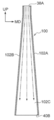
- FIG. 3A an outline of the flow of the blown air in the diffusion shaft 36 is shown by a two-dot chain line arrow.
- FIG. 3B shows a diffusion shaft 100 to be compared.
- a wall portion 102A and a wall portion 102B are arranged in pairs along the MD direction, and a pair of side wall portions 102C (only one is shown in FIG. 3B) is arranged in the CD direction.
- the diffusion shaft 100 is formed in a cylindrical shape in which the wall portions 102A and 102B are inclined so that the opening cross section gradually expands from the upper side to the lower side, the opening 38A is provided at the upper end, and the opening is provided at the lower end. 40B is provided. That is, the diffusion shaft 100 is different from the diffusion shaft 36 in that the step portion 42 is not provided.
- the blown air introduced from the opening 38A is expanded in the MD direction according to the expansion of the opening width of the diffusion shaft 100 and is discharged from the opening 40B.
- the speed of the blown air fluctuates according to friction between the walls 102A and 102B and the inner surface of the side wall 102C and the opening width, but the diffusion shaft 100 suppresses the speed fluctuation. Is done. Therefore, in the diffusion shaft 100, since fluctuations in the speed of the blast air are suppressed, the entanglement of the plurality of filaments conveyed by the blast air in the diffusion shaft 100 is suppressed.
- the diffusion shaft 36 is provided with connecting wall portions 48 ⁇ / b> A and 48 ⁇ / b> B that extend in the horizontal direction on the step portion 42.
- the main wind flow is indicated by a two-dot chain arrow).
- the blown wind causes a fluctuation in speed as a whole by spreading.
- the diffusion shaft 36 is provided with a stepped portion 42 having a larger change in opening width than the upper shaft 38 and the lower shaft 40, and the blowout air is expanded in the stepped portion 42.
- a plurality of filaments conveyed by the blown air are slightly entangled with each other, and a region in which the speed fluctuation is promoted from the surroundings in the blown air is generated. Promoted.
- the filament ejected from the diffusion shaft 36 provided with the stepped portion 42 is entangled more than the filament ejected from the diffusion shaft 100 not provided with the stepped portion 42. Therefore, a web on which filaments with many entanglements are deposited is generated on the collection surface 32A of the collection unit 18.
- a nonwoven fabric has a high strength compared to a case where a filament has a small amount of entanglement due to an increase in the entanglement of the filament. Therefore, the manufacturing apparatus 10 can produce a non-woven fabric with high strength by providing the step portion 42 on the diffusion shaft 36.
- the lower shaft 40 is biased in the MD direction with respect to the upper shaft 38 by making the width dimension (MD direction dimension) of the connecting wall portion 48A larger than the width dimension of the connecting wall portion 48B.
- the diffusion shaft 36 has been described as an example, the diffusion shaft is not limited to this.
- FIG. 4A to 4C show a diffusion shaft having a shape different from that of the diffusion shaft 36.
- FIG. 4A The diffusion shaft 50 shown in FIG. 4A is provided with a stepped portion 52 between the upper shaft 38 and the lower shaft 40, and the stepped portion 52 is provided with a connecting wall portion 54 disposed in the horizontal direction. ing.
- the wall portion 44B of the upper shaft 38 and the wall portion 46B of the lower shaft 40 are connected.
- the lower end of the wall portion 44 ⁇ / b> A of the upper shaft 38 and the upper end of the wall portion 46 ⁇ / b> A of the lower shaft 40 are connected by the connecting wall portion 54 of the step portion 52.
- the stepped portion 52 of the diffusion shaft 50 has an opening width widened by a step formed between the inner surface of the wall portion 44A and the inner surface of the wall portion 46A, and the blown air passing through the stepped portion 52 is on the MD direction side. To spread. Therefore, in the diffusion shaft 50, a region in which the speed fluctuation is promoted in the blown air diffused in the lower shaft 40 is generated, and the entanglement of the filament is promoted by promoting the speed fluctuation of the blown air. Therefore, the use of the diffusion shaft 50 makes it possible to produce a non-woven fabric with high strength.
- the stepped portion may be formed by connecting the upper shaft 38 and the lower shaft 40 by forming a step in the MD direction and the direction opposite to the MD direction by the connecting wall portion having the same width.
- the diffusion shaft has a stepped portion whose opening width increases in at least one direction opposite to the MD direction and the MD direction at the connection portion between the first shaft portion and the second shaft portion. It ’s fine.
- the upper shaft 38 and the lower shaft 40 are connected by a stepped portion 58.
- connecting wall portions 60A and 60B and a connecting side wall portion 60C having the same width are used, and the connecting wall portions 60A and 60B are inclined so that the lower shaft 40 side is the lower side with respect to the horizontal direction.
- the side wall portion 44C of the upper shaft 38 and the side wall portion 46C of the lower shaft 40 are connected by the connecting side wall portion 60C.
- the wall portion 44A of the upper shaft 38 and the wall portion 46A of the lower shaft 40 are connected by the connecting wall portion 60A, and the wall portion 44B of the upper shaft 38 and the wall portion 46B of the lower shaft 40 are connected. It is connected by a wall 60B.
- the inclination of the connecting wall portions 60A and 60B in the step portion 58 of the diffusion shaft 56 is caused by the change in the opening width between the connecting wall portions 60A and 60B.
- the slope can be promoted.
- the diffusion shaft 56 formed in this way can promote the occurrence of entanglement in the filament by generating a region in which the speed fluctuation is promoted in the blown air that has passed through the stepped portion 58, and the high-strength nonwoven fabric. Manufacture is possible.
- the opening width of the upper opening 38 ⁇ / b> A is narrower than the lower opening 38 ⁇ / b> B of the upper shaft 38.
- the stepped portion 64 of the diffusion shaft 62 is provided with a connecting wall portion 66A on the MD direction side and a connecting wall portion 66B on the opposite side to the MD direction.
- An arcuate curved portion 68A that protrudes downward is disposed on the upper side of the connecting wall portions 66A and 66B, and a circle that protrudes upward on the lower side of the connecting wall portions 66A and 66B.
- An arcuate curved portion 68B is arranged.
- the connecting wall portion 66A is formed by connecting curved portions 68A and 68B.
- the stepped portion 64 is provided with connecting wall portions 66A and 66B with the convex surface side of the curved portion 68A facing each other. Further, the stepped portion 64 is provided with a pair of connecting side wall portions 66C on the CD direction side, and the connecting wall portions 66A and 66B are connected by the connecting side wall portion 66C.
- the wall portion 44A of the upper shaft 38 and the wall portion 46A of the lower shaft 40 are connected by the connecting wall portion 66A, and the wall portion 44B of the upper shaft 38 and the wall portion 46B of the lower shaft 40 are connected to the connecting wall portion. It is connected by 66B.
- the side wall portion 44C of the upper shaft 38 and the side wall portion 46C of the lower shaft 40 are connected by the connecting side wall portion 66C.
- the stepped portion 64 of the diffusion shaft 62 uses the connecting wall portions 66A and 66B whose inner surfaces are curved, and the opening width is changed so as to expand from the upper end to the lower end,
- the change rate of the opening width is set larger in the middle part than in the upper part and the lower part.
- a step is formed in the entire area in the CD direction for at least one of the MD direction side and the opposite side to the MD direction.
- stepped portions may be formed alternately.
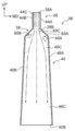
- FIG. 5 shows a diffusion shaft 70 as an example of this.
- the diffusion shaft 70 includes a lower shaft 72 as a second shaft portion, and the upper shaft 38 and the lower shaft 72 are connected at a stepped portion 74.
- the lower shaft 72 has a wall portion 76 disposed on the MD direction side, and a wall portion 78 disposed on the opposite side to the MD direction.
- the lower shaft 72 is formed in a substantially cylindrical shape in which a pair of side wall portions 80 are disposed on the CD direction side, the wall portions 76 and 78 are connected by the side wall portion 80, and the lower end is an opening 40B.
- the stepped portion 74 includes a stepped portion 74A as a first stepped portion provided on the MD direction side (wall portion 76 side), and a second stepped portion provided on the side opposite to the MD direction (wall portion 78 side).
- a stepped portion 74B as a stepped portion is included.
- the wall portion 76 of the lower shaft 72 includes a vertical wall 82A whose upper end is in contact with the lower end of the wall portion 44A of the upper shaft 38, and a vertical wall 82B whose upper end is separated in the MD direction from the lower end of the wall portion 44A of the upper shaft 38.
- a vertical wall 82A and 82B are connected by a side wall 82C.
- the stepped portion 74A is formed by connecting the lower end of the wall portion 44A and the upper end of the vertical wall 82B of the wall portion 76 by a connecting wall portion 84A arranged in the horizontal direction. Accordingly, step portions 74A are formed on the diffusion shaft 70 at predetermined intervals along the CD direction.
- the wall portion 78 of the lower shaft 72 has a vertical wall 86A whose upper end is in contact with the lower end of the wall portion 44B of the upper shaft 38, and an upper end that is separated from the lower end of the wall portion 44B of the upper shaft 38 in a direction opposite to the MD direction.
- the vertical walls 86B are alternately arranged in the CD direction, and the adjacent vertical walls 86A and 86B are connected by a side wall 86C.
- the stepped portion 74B is formed by connecting the lower end of the wall portion 44B of the upper shaft 38 and the upper end of the vertical wall 86B of the wall portion 78 by a connecting wall portion 84B arranged in the horizontal direction.
- the diffusion shaft 70 has stepped portions 74B formed at predetermined intervals along the CD direction.
- the wall 78 has a vertical wall 86 ⁇ / b> A facing the vertical wall 82 ⁇ / b> B of the wall 76, and a vertical wall 86 ⁇ / b> B facing the vertical wall 82 ⁇ / b> A of the wall 76.
- the stepped portions 74A and the stepped portions 74B are alternately formed along the CD direction.
- the diffusion shaft 70 formed in this way has stepped portions 74A and 74B whose opening width changes so as to promote the speed fluctuation of the blown air between the upper shaft 38 and the lower shaft 72. Thereby, the diffusion shaft 70 can promote the occurrence of entanglement in the filament, and it is possible to produce a high-strength nonwoven fabric.
- the diffusion shaft 70 is provided with step portions 74A on the MD direction side and step portions 74B on the opposite side to the MD direction, which are alternately provided along the CD direction. Can be prevented from changing, and a nonwoven fabric with high uniformity and strength can be produced.
Landscapes
- Engineering & Computer Science (AREA)
- Textile Engineering (AREA)
- Mechanical Engineering (AREA)
- Spinning Methods And Devices For Manufacturing Artificial Fibers (AREA)
- Nonwoven Fabrics (AREA)
Abstract
Priority Applications (8)
| Application Number | Priority Date | Filing Date | Title |
|---|---|---|---|
| MYPI2018703538A MY194243A (en) | 2016-03-30 | 2017-03-24 | Apparatus for manufacturing non-woven fabric and method of manufacturing non-woven fabric |
| KR1020207013089A KR20200052988A (ko) | 2016-03-30 | 2017-03-24 | 부직포의 제조 장치 및 부직포의 제조 방법 |
| DK17774779.7T DK3428333T3 (da) | 2016-03-30 | 2017-03-24 | Indretning til fremstilling af ikkevævet stof og fremgangsmåde til fremstilling af ikkevævet stof |
| EP17774779.7A EP3428333B1 (fr) | 2016-03-30 | 2017-03-24 | Dispositif de fabrication de tissu non tissé et procédé de fabrication de tissu non tissé |
| US16/089,090 US10947652B2 (en) | 2016-03-30 | 2017-03-24 | Apparatus for manufacturing non-woven fabric and method of manufacturing non-woven fabric |
| JP2018509252A JPWO2017170242A1 (ja) | 2016-03-30 | 2017-03-24 | 不織布の製造装置及び不織布の製造方法 |
| CN201780020569.6A CN109072519B (zh) | 2016-03-30 | 2017-03-24 | 无纺布的制造装置及无纺布的制造方法 |
| KR1020187028247A KR102259649B1 (ko) | 2016-03-30 | 2017-03-24 | 부직포의 제조 장치 및 부직포의 제조 방법 |
Applications Claiming Priority (2)
| Application Number | Priority Date | Filing Date | Title |
|---|---|---|---|
| JP2016-068805 | 2016-03-30 | ||
| JP2016068805 | 2016-03-30 |
Publications (1)
| Publication Number | Publication Date |
|---|---|
| WO2017170242A1 true WO2017170242A1 (fr) | 2017-10-05 |
Family
ID=59964526
Family Applications (1)
| Application Number | Title | Priority Date | Filing Date |
|---|---|---|---|
| PCT/JP2017/012063 Ceased WO2017170242A1 (fr) | 2016-03-30 | 2017-03-24 | Dispositif de fabrication de tissu non tissé et procédé de fabrication de tissu non tissé |
Country Status (8)
| Country | Link |
|---|---|
| US (1) | US10947652B2 (fr) |
| EP (1) | EP3428333B1 (fr) |
| JP (2) | JPWO2017170242A1 (fr) |
| KR (2) | KR102259649B1 (fr) |
| CN (1) | CN109072519B (fr) |
| DK (1) | DK3428333T3 (fr) |
| MY (1) | MY194243A (fr) |
| WO (1) | WO2017170242A1 (fr) |
Families Citing this family (2)
| Publication number | Priority date | Publication date | Assignee | Title |
|---|---|---|---|---|
| CN111254587A (zh) * | 2020-04-21 | 2020-06-09 | 大连天马可溶制品有限公司 | 三角箱式铺网装置 |
| CN120119349B (zh) * | 2025-05-13 | 2025-07-25 | 浙江朝隆纺织机械有限公司 | 一种抽单体结构及使用该结构的纺粘法纺丝箱 |
Citations (6)
| Publication number | Priority date | Publication date | Assignee | Title |
|---|---|---|---|---|
| JPS481471A (fr) * | 1971-06-01 | 1973-01-10 | ||
| JPH06248556A (ja) * | 1993-02-23 | 1994-09-06 | Toray Ind Inc | 繊維ウエブ製造装置 |
| JP2001288670A (ja) * | 2000-03-30 | 2001-10-19 | Uni Charm Corp | 不織布の製造方法および装置 |
| JP2002371428A (ja) * | 2001-06-08 | 2002-12-26 | Kobe Steel Ltd | 糸条延伸装置 |
| JP2003213561A (ja) * | 2001-12-17 | 2003-07-30 | Reifenhaeuser Gmbh & Co Mas Fab | スパンボンデット不織布を製造するための装置 |
| JP2009013559A (ja) * | 2007-06-29 | 2009-01-22 | Reifenhaeuser Gmbh & Co Kg Maschinenfabrik | スパンボンドウエブを形成する装置 |
Family Cites Families (14)
| Publication number | Priority date | Publication date | Assignee | Title |
|---|---|---|---|---|
| DE3807420A1 (de) | 1988-03-07 | 1989-09-21 | Gruenzweig & Hartmann | Einrichtung zur erzeugung von fasern, insbesondere mineralfasern, aus einer schmelze |
| DE4312419C2 (de) | 1993-04-16 | 1996-02-22 | Reifenhaeuser Masch | Anlage für die Herstellung einer Spinnvliesbahn aus aerodynamischen verstreckten Filamenten aus Kunststoff |
| DE4332345C2 (de) | 1993-09-23 | 1995-09-14 | Reifenhaeuser Masch | Verfahren und Vliesblasanlage zur Herstellung von einem Spinnvlies mit hoher Filamentgeschwindigkeit |
| DE4414277C1 (de) * | 1994-04-23 | 1995-08-31 | Reifenhaeuser Masch | Nach dem Ruhedruckprinzip arbeitende Spinnvliesanlage für die Herstellung einer Nonwoven-Spinnvliesbahn |
| DE19504953C2 (de) | 1995-02-15 | 1999-05-20 | Reifenhaeuser Masch | Anlage für die Herstellung einer Spinnvliesbahn aus thermoplastischen Endlosfäden |
| DE19521466C2 (de) | 1995-06-13 | 1999-01-14 | Reifenhaeuser Masch | Anlage für die Herstellung einer Spinnvliesbahn aus thermoplastischen Endlosfäden |
| US5795517A (en) * | 1996-05-03 | 1998-08-18 | Owens-Corning Canada | Collection and deposition of chopped fibrous strands for formation into non-woven webs of bonded chopped fibers |
| FR2792656B1 (fr) | 1999-04-23 | 2001-06-01 | Icbt Perfojet Sa | Dispositif permettant d'assurer l'ouverture et la repartition d'un faisceau de filaments lors de la realisation d'une nappe textile non tissee |
| JP4191364B2 (ja) | 1999-04-26 | 2008-12-03 | ユニチカ株式会社 | 面ファスナ雌材用不織布の製造方法 |
| JP3658284B2 (ja) * | 2000-07-05 | 2005-06-08 | ユニ・チャーム株式会社 | 不織布製造装置 |
| US8206640B2 (en) * | 2003-07-25 | 2012-06-26 | The University Of Tennessee Research Foundation | Process for collection of continuous fibers as a uniform batt |
| DE502005006763D1 (de) | 2004-09-24 | 2009-04-16 | Oerlikon Textile Gmbh & Co Kg | Vorrichtung zur ablage von synthetischen fasern zu einem vlies |
| JP2011241510A (ja) | 2010-05-19 | 2011-12-01 | Toyota Boshoku Corp | 溶融紡糸方法及び溶融紡糸装置 |
| DE502012009274C5 (de) * | 2011-10-22 | 2022-01-20 | Oerlikon Textile Gmbh & Co. Kg | Vorrichtung und Verfahren zum Führen und Ablegen von synthetischen Filamenten zu einem Vlies |
-
2017
- 2017-03-24 DK DK17774779.7T patent/DK3428333T3/da active
- 2017-03-24 KR KR1020187028247A patent/KR102259649B1/ko active Active
- 2017-03-24 US US16/089,090 patent/US10947652B2/en active Active
- 2017-03-24 EP EP17774779.7A patent/EP3428333B1/fr active Active
- 2017-03-24 CN CN201780020569.6A patent/CN109072519B/zh active Active
- 2017-03-24 WO PCT/JP2017/012063 patent/WO2017170242A1/fr not_active Ceased
- 2017-03-24 JP JP2018509252A patent/JPWO2017170242A1/ja active Pending
- 2017-03-24 KR KR1020207013089A patent/KR20200052988A/ko not_active Abandoned
- 2017-03-24 MY MYPI2018703538A patent/MY194243A/en unknown
-
2020
- 2020-02-04 JP JP2020017312A patent/JP6842577B2/ja active Active
Patent Citations (6)
| Publication number | Priority date | Publication date | Assignee | Title |
|---|---|---|---|---|
| JPS481471A (fr) * | 1971-06-01 | 1973-01-10 | ||
| JPH06248556A (ja) * | 1993-02-23 | 1994-09-06 | Toray Ind Inc | 繊維ウエブ製造装置 |
| JP2001288670A (ja) * | 2000-03-30 | 2001-10-19 | Uni Charm Corp | 不織布の製造方法および装置 |
| JP2002371428A (ja) * | 2001-06-08 | 2002-12-26 | Kobe Steel Ltd | 糸条延伸装置 |
| JP2003213561A (ja) * | 2001-12-17 | 2003-07-30 | Reifenhaeuser Gmbh & Co Mas Fab | スパンボンデット不織布を製造するための装置 |
| JP2009013559A (ja) * | 2007-06-29 | 2009-01-22 | Reifenhaeuser Gmbh & Co Kg Maschinenfabrik | スパンボンドウエブを形成する装置 |
Non-Patent Citations (1)
| Title |
|---|
| See also references of EP3428333A4 * |
Also Published As
| Publication number | Publication date |
|---|---|
| JPWO2017170242A1 (ja) | 2018-10-04 |
| KR20200052988A (ko) | 2020-05-15 |
| JP2020073748A (ja) | 2020-05-14 |
| CN109072519B (zh) | 2021-10-01 |
| EP3428333B1 (fr) | 2021-02-03 |
| DK3428333T3 (da) | 2021-03-01 |
| CN109072519A (zh) | 2018-12-21 |
| EP3428333A1 (fr) | 2019-01-16 |
| EP3428333A4 (fr) | 2019-08-21 |
| JP6842577B2 (ja) | 2021-03-17 |
| US10947652B2 (en) | 2021-03-16 |
| KR102259649B1 (ko) | 2021-06-01 |
| MY194243A (en) | 2022-11-24 |
| US20190127897A1 (en) | 2019-05-02 |
| KR20180118190A (ko) | 2018-10-30 |
Similar Documents
| Publication | Publication Date | Title |
|---|---|---|
| JP3725866B2 (ja) | スパンボンド不織布製造プロセスおよびその製造システム | |
| CN101636532B (zh) | 用发散的纤维拉丝单元来增进纤维束分散的方法及设备 | |
| KR840000196B1 (ko) | 부직 웨브의 제조장치 | |
| KR101031801B1 (ko) | 부직포를 제조하는 방법 및 장치 | |
| KR102481045B1 (ko) | 필라멘트로 방사 접합 직물을 제조하기 위한 방사 방법 및 장치, 그리고 그로부터 제조되는 방사 접합 직물 | |
| JP4549541B2 (ja) | 不織布ウェブの製造中に繊維束を開繊し分配する装置 | |
| JP2022010113A (ja) | スパンボンド不織布 | |
| CN101087904A (zh) | 适于熔喷设备的低湍流模具组件 | |
| JP6842577B2 (ja) | 不織布の製造装置及び不織布の製造方法 | |
| EP2126165B1 (fr) | Procédé et appareil pour étirer et déposer une pluralité de fibres pour former un non-tissé | |
| US6499981B1 (en) | Drawing unit | |
| JP4334342B2 (ja) | フィラメント延伸ジェット装置および方法 | |
| RU2710675C1 (ru) | Устройство для изготовления фильерных нетканых материалов | |
| CN111868312B (zh) | 拉伸装置、以及纤维及纤维网的制造装置及制造方法 | |
| JP2002371428A (ja) | 糸条延伸装置 | |
| JP2021120495A (ja) | 不織布製造方法、および不織布製造装置 | |
| JP2017145529A (ja) | 不織布製造装置及び不織布製造方法 | |
| CN112442743B (zh) | 熔喷装置 | |
| JP7096294B2 (ja) | 繊維から不織布を製造するための装置及び方法 | |
| JP2025139549A (ja) | 不織布の製造装置および不織布の製造方法 | |
| CN117500963A (zh) | 无纺布的制造装置及制造方法 |
Legal Events
| Date | Code | Title | Description |
|---|---|---|---|
| ENP | Entry into the national phase |
Ref document number: 2018509252 Country of ref document: JP Kind code of ref document: A |
|
| ENP | Entry into the national phase |
Ref document number: 20187028247 Country of ref document: KR Kind code of ref document: A |
|
| NENP | Non-entry into the national phase |
Ref country code: DE |
|
| WWE | Wipo information: entry into national phase |
Ref document number: 2017774779 Country of ref document: EP |
|
| ENP | Entry into the national phase |
Ref document number: 2017774779 Country of ref document: EP Effective date: 20181011 |
|
| 121 | Ep: the epo has been informed by wipo that ep was designated in this application |
Ref document number: 17774779 Country of ref document: EP Kind code of ref document: A1 |