WO2017170937A1 - Procédé de changement de tranche et dispositif de changement de tranche - Google Patents
Procédé de changement de tranche et dispositif de changement de tranche Download PDFInfo
- Publication number
- WO2017170937A1 WO2017170937A1 PCT/JP2017/013409 JP2017013409W WO2017170937A1 WO 2017170937 A1 WO2017170937 A1 WO 2017170937A1 JP 2017013409 W JP2017013409 W JP 2017013409W WO 2017170937 A1 WO2017170937 A1 WO 2017170937A1
- Authority
- WO
- WIPO (PCT)
- Prior art keywords
- slice
- service
- unit
- connection destination
- resource
- Prior art date
- Legal status (The legal status is an assumption and is not a legal conclusion. Google has not performed a legal analysis and makes no representation as to the accuracy of the status listed.)
- Ceased
Links
Images







Classifications
-
- H—ELECTRICITY
- H04—ELECTRIC COMMUNICATION TECHNIQUE
- H04L—TRANSMISSION OF DIGITAL INFORMATION, e.g. TELEGRAPHIC COMMUNICATION
- H04L41/00—Arrangements for maintenance, administration or management of data switching networks, e.g. of packet switching networks
- H04L41/50—Network service management, e.g. ensuring proper service fulfilment according to agreements
- H04L41/5041—Network service management, e.g. ensuring proper service fulfilment according to agreements characterised by the time relationship between creation and deployment of a service
- H04L41/5054—Automatic deployment of services triggered by the service manager, e.g. service implementation by automatic configuration of network components
-
- G—PHYSICS
- G06—COMPUTING OR CALCULATING; COUNTING
- G06F—ELECTRIC DIGITAL DATA PROCESSING
- G06F9/00—Arrangements for program control, e.g. control units
- G06F9/06—Arrangements for program control, e.g. control units using stored programs, i.e. using an internal store of processing equipment to receive or retain programs
- G06F9/44—Arrangements for executing specific programs
- G06F9/455—Emulation; Interpretation; Software simulation, e.g. virtualisation or emulation of application or operating system execution engines
-
- H—ELECTRICITY
- H04—ELECTRIC COMMUNICATION TECHNIQUE
- H04L—TRANSMISSION OF DIGITAL INFORMATION, e.g. TELEGRAPHIC COMMUNICATION
- H04L41/00—Arrangements for maintenance, administration or management of data switching networks, e.g. of packet switching networks
- H04L41/08—Configuration management of networks or network elements
- H04L41/0803—Configuration setting
- H04L41/0813—Configuration setting characterised by the conditions triggering a change of settings
-
- H—ELECTRICITY
- H04—ELECTRIC COMMUNICATION TECHNIQUE
- H04L—TRANSMISSION OF DIGITAL INFORMATION, e.g. TELEGRAPHIC COMMUNICATION
- H04L41/00—Arrangements for maintenance, administration or management of data switching networks, e.g. of packet switching networks
- H04L41/08—Configuration management of networks or network elements
- H04L41/0803—Configuration setting
- H04L41/0813—Configuration setting characterised by the conditions triggering a change of settings
- H04L41/0816—Configuration setting characterised by the conditions triggering a change of settings the condition being an adaptation, e.g. in response to network events
-
- H—ELECTRICITY
- H04—ELECTRIC COMMUNICATION TECHNIQUE
- H04L—TRANSMISSION OF DIGITAL INFORMATION, e.g. TELEGRAPHIC COMMUNICATION
- H04L41/00—Arrangements for maintenance, administration or management of data switching networks, e.g. of packet switching networks
- H04L41/08—Configuration management of networks or network elements
- H04L41/0889—Techniques to speed-up the configuration process
-
- H—ELECTRICITY
- H04—ELECTRIC COMMUNICATION TECHNIQUE
- H04L—TRANSMISSION OF DIGITAL INFORMATION, e.g. TELEGRAPHIC COMMUNICATION
- H04L41/00—Arrangements for maintenance, administration or management of data switching networks, e.g. of packet switching networks
- H04L41/08—Configuration management of networks or network elements
- H04L41/0896—Bandwidth or capacity management, i.e. automatically increasing or decreasing capacities
-
- H—ELECTRICITY
- H04—ELECTRIC COMMUNICATION TECHNIQUE
- H04L—TRANSMISSION OF DIGITAL INFORMATION, e.g. TELEGRAPHIC COMMUNICATION
- H04L41/00—Arrangements for maintenance, administration or management of data switching networks, e.g. of packet switching networks
- H04L41/12—Discovery or management of network topologies
- H04L41/122—Discovery or management of network topologies of virtualised topologies, e.g. software-defined networks [SDN] or network function virtualisation [NFV]
-
- H—ELECTRICITY
- H04—ELECTRIC COMMUNICATION TECHNIQUE
- H04L—TRANSMISSION OF DIGITAL INFORMATION, e.g. TELEGRAPHIC COMMUNICATION
- H04L41/00—Arrangements for maintenance, administration or management of data switching networks, e.g. of packet switching networks
- H04L41/50—Network service management, e.g. ensuring proper service fulfilment according to agreements
-
- H—ELECTRICITY
- H04—ELECTRIC COMMUNICATION TECHNIQUE
- H04L—TRANSMISSION OF DIGITAL INFORMATION, e.g. TELEGRAPHIC COMMUNICATION
- H04L41/00—Arrangements for maintenance, administration or management of data switching networks, e.g. of packet switching networks
- H04L41/50—Network service management, e.g. ensuring proper service fulfilment according to agreements
- H04L41/5003—Managing SLA; Interaction between SLA and QoS
- H04L41/5019—Ensuring fulfilment of SLA
- H04L41/5025—Ensuring fulfilment of SLA by proactively reacting to service quality change, e.g. by reconfiguration after service quality degradation or upgrade
-
- H—ELECTRICITY
- H04—ELECTRIC COMMUNICATION TECHNIQUE
- H04L—TRANSMISSION OF DIGITAL INFORMATION, e.g. TELEGRAPHIC COMMUNICATION
- H04L45/00—Routing or path finding of packets in data switching networks
- H04L45/38—Flow based routing
-
- H—ELECTRICITY
- H04—ELECTRIC COMMUNICATION TECHNIQUE
- H04L—TRANSMISSION OF DIGITAL INFORMATION, e.g. TELEGRAPHIC COMMUNICATION
- H04L45/00—Routing or path finding of packets in data switching networks
- H04L45/40—Wormhole routing
-
- H—ELECTRICITY
- H04—ELECTRIC COMMUNICATION TECHNIQUE
- H04L—TRANSMISSION OF DIGITAL INFORMATION, e.g. TELEGRAPHIC COMMUNICATION
- H04L67/00—Network arrangements or protocols for supporting network services or applications
- H04L67/14—Session management
- H04L67/148—Migration or transfer of sessions
-
- H—ELECTRICITY
- H04—ELECTRIC COMMUNICATION TECHNIQUE
- H04W—WIRELESS COMMUNICATION NETWORKS
- H04W28/00—Network traffic management; Network resource management
- H04W28/16—Central resource management; Negotiation of resources or communication parameters, e.g. negotiating bandwidth or QoS [Quality of Service]
- H04W28/18—Negotiating wireless communication parameters
-
- H—ELECTRICITY
- H04—ELECTRIC COMMUNICATION TECHNIQUE
- H04W—WIRELESS COMMUNICATION NETWORKS
- H04W4/00—Services specially adapted for wireless communication networks; Facilities therefor
- H04W4/50—Service provisioning or reconfiguring
-
- H—ELECTRICITY
- H04—ELECTRIC COMMUNICATION TECHNIQUE
- H04W—WIRELESS COMMUNICATION NETWORKS
- H04W76/00—Connection management
- H04W76/10—Connection setup
- H04W76/19—Connection re-establishment
-
- G—PHYSICS
- G06—COMPUTING OR CALCULATING; COUNTING
- G06F—ELECTRIC DIGITAL DATA PROCESSING
- G06F9/00—Arrangements for program control, e.g. control units
- G06F9/06—Arrangements for program control, e.g. control units using stored programs, i.e. using an internal store of processing equipment to receive or retain programs
- G06F9/44—Arrangements for executing specific programs
- G06F9/455—Emulation; Interpretation; Software simulation, e.g. virtualisation or emulation of application or operating system execution engines
- G06F9/45533—Hypervisors; Virtual machine monitors
- G06F9/45558—Hypervisor-specific management and integration aspects
- G06F2009/45575—Starting, stopping, suspending or resuming virtual machine instances
-
- H—ELECTRICITY
- H04—ELECTRIC COMMUNICATION TECHNIQUE
- H04L—TRANSMISSION OF DIGITAL INFORMATION, e.g. TELEGRAPHIC COMMUNICATION
- H04L41/00—Arrangements for maintenance, administration or management of data switching networks, e.g. of packet switching networks
- H04L41/08—Configuration management of networks or network elements
- H04L41/0895—Configuration of virtualised networks or elements, e.g. virtualised network function or OpenFlow elements
Definitions
- the present invention relates to a slice changing method and a slice changing device for changing a slice.
- a network system using a conventional virtualization technology is a virtual network that is logically generated on a network infrastructure by virtually separating hardware resources using the virtualization technology disclosed in Non-Patent Document 1. Create a slice. Then, by assigning a service to the slice, it is possible to provide the service using a network of independent slices. Thereby, when a slice is assigned to each service having various requirements, it becomes easy to satisfy the requirements of each service, and the signaling processing and the like can be reduced.
- the present invention has been made in view of the above, and an object of the present invention is to provide a slice changing method and a slice changing device for changing a slice without instantaneous interruption.
- a slice changing method is a slice changing method of a communication system that changes a slice that is a virtual network generated on a network infrastructure, and a condition for changing the slice If satisfying, the acquisition step of acquiring the connection destination of the slice after the change, the notification step of notifying the connection destination acquired by the acquisition step to the communication device that connects the terminal using the slice and the connection destination of the slice, and notification After the notification by the step, a release step of releasing resources related to the slice before the change is included.
- the slice change device is a slice change device included in a communication system that changes a slice that is a virtual network generated on a network infrastructure, and satisfies a condition for changing a slice,
- An acquisition unit for acquiring the connection destination of the slice after the change, a notification unit for notifying the connection destination acquired by the acquisition unit to a communication device that connects the terminal using the slice and the connection destination of the slice, and a notification by the notification unit
- release means for releasing resources related to the slice before the change.
- the connection destination of the slice after the change is acquired, and before the resources related to the slice before the change are released, the acquired connection destination is set as a communication device. To notify.
- the connection destination can be changed at the timing when the slice is changed without inquiring about the change of the connection destination from the communication apparatus side. That is, the slice can be changed without interruption.
- the notification step may perform notification after making a connection request to the connection destination of the slice.
- the notification since the notification is made after a connection request is made to the service connection destination, the terminal can be appropriately connected to the service connection destination in accordance with the notification.
- the condition is determined based on the resource usage status of the slice, and the acquisition step may acquire the connection destination of the slice after the change determined according to the resource usage status for each slice. .
- the service connection destination can be changed based on the resource load.
- the service used by the terminal is assigned to the slice, and if the condition for changing the slice is satisfied, the service may be assigned to the slice after the change.
- the service since the connection destination of the slice to which the service is allocated is notified to the communication device before releasing the resources related to the slice before the change, the service can be used without instantaneous interruption.
- the slice can be changed without interruption.
- FIG. 1 shows a configuration of a communication system including a service mapping apparatus 10 according to the present embodiment.
- the communication system is a communication system that allocates services to slices that are virtual networks.
- a slice is a virtual network or service network that is created by logically dividing the network device link and node resources and combining the separated resources, and the slices separate resources. And do not interfere with each other.
- the service refers to a service using network resources such as a communication service (private line service or the like) or an application service (service using a moving image distribution or sensor device such as an embedded device).
- the communication system includes a service mapping device 10, an SO (Service Operator) 20, an OSS / BSS (Operations Support System / Business Support System) 30, an NFVO 40, a VNFM 50, and a VIM (Virtualized Infrastructure Management).
- Virtualization infrastructure management 60, HSS (Home Subscriber Server) 70, DNS (Domain Name System) server 80, MME (Mobility Management Entity) 90 (slice changing device), eNB 100, and SGW (Serving Gateway) 110 (SGW110A to SGW110C), PGW (Packet data network gateway) 120 (PGW120A to PGW120C), and UE (User Equipment) 130.
- NFVO40, VNFM50, and VIM60 are MANO (Management & Orchestration) architecture.
- the identifier of the SGW 110A is “SGW1”, the identifier of the SGW 110B is “SGW2”, and the identifier of the SGW 110C is “SGW3”.
- the identifier of the PGW 120A is “PGW1”, the identifier of the PGW 120B is “PGW2”, and the identifier of the PGW 120C is “PGW3”.
- components constitute the core network of the communication system. Note that components that need to transmit and receive information to each other are connected by wire or the like so that information can be transmitted and received.
- the communication system provides a communication function to the mobile communication terminal (UE 130) by a virtual server that operates in a virtual machine realized on a physical server. That is, the communication system is a virtualized mobile communication network.
- the communication function is provided to the mobile communication terminal by executing a communication process corresponding to the communication function by the virtual machine.
- the service mapping apparatus 10 is a node that performs service management in the communication system and gives instructions related to communication functions in the communication system. Further, the service mapping apparatus 10 can be operated by a telecommunications carrier related to the communication system.
- the SO (Service Operator) 20 is a service requesting device, for example, a terminal device (for example, a personal computer) of a business provider that provides services to various users using a virtual network.
- a service requesting device for example, a terminal device (for example, a personal computer) of a business provider that provides services to various users using a virtual network.
- the OSS / BSS 30 is a device that receives a service request from the SO 20 and notifies the service mapping device 10 of the request.
- the NFVO 40 is an overall management node (functional entity) that manages the entire virtual network (slice) constructed on the NFVI 160, which is a physical resource.
- the NFVO 40 receives an instruction from the service mapping apparatus 10 and performs processing according to the instruction.
- the NFVO 40 performs management over the entire virtual network constructed in the physical resources of the mobile communication network of infrastructure and communication services.
- the NFVO 40 implements a communication service provided by the virtual network at an appropriate location via the VNFM 50 and the VIM 60.
- service life cycle management (specifically, for example, generation, update, scale control, event collection), resource distribution / reservation / allocation management, service / instance management, and policy management (in the mobile communication network) Specifically, for example, resource reservation / allocation, optimal placement based on geography / laws, etc.) is performed.
- the VNFM 50 is a virtual communication function management node (functional entity) that adds a function related to a service to the NFVI 160 serving as a physical resource (node).
- a plurality of VNFMs 50 may be provided in the communication system.
- the VIM 60 is a physical resource management node (functional entity) that manages each physical resource (node). Specifically, resource allocation / update / recovery management, association between physical resources and virtualized network, and management of hardware resources and SW resources (hypervisor) list are performed. Normally, the VIM 60 performs management for each data center (station building). Management of physical resources is performed by a method according to the data center. Data center management methods (management resource mounting methods) include OPENSTACK and vCenter. Normally, the VIM 60 is provided for each data center management method. That is, a plurality of VIMs 60 that manage each physical resource in the NFVI 160 in different manners are included. Note that the unit of physical resources managed by different management methods is not necessarily a data center unit.
- the NFVO 40, the VNFM 50, and the VIM 60 are realized by executing a program on a physical server device (however, they are not limited to being realized on virtualization, and are separated from a management system). And may be realized on virtualization).
- the NFVO 40, the VNFM 50, and the VIM 60 may be realized by separate physical server devices, or may be realized by the same server device.
- the NFVO 40, VNFM 50, and VIM 60 (programs for realizing) may be provided from different vendors.
- the NFVO 40 When the NFVO 40 receives the slice generation request, the NFVO 40 makes a resource securing request for the slice (slice SL1, SL2, etc.) to the VIM 60.
- the VIM 60 secures resources in the server devices and switches that make up physical resources, the NFVO 40 defines slices for these physical resources.
- the NFVO 40 when the NFVO 40 causes the VIM 60 to secure a resource in the physical resource, the NFVO 40 stores information defining a slice for the physical resource in a table stored in the NFVO 40. Then, the NFVO 40 requests the VNFM 50 to install software for realizing functions required for the service. In response to the installation request, the VNFM 50 installs the software on a physical resource (node such as a server device, a switch device, or a router device) secured by the VIM 60.
- a physical resource node such as a server device, a switch device, or a router device
- the slices SL1 to SL3 are slices that are units for allocating services. It is assumed that the identifier (NW Slice ID) of the slice SL1 is “1”, the identifier of the slice SL2 is “2”, and the identifier of the slice SL3 is “3”.
- the NFVO 40 when the NFVO 40 makes a resource securing request for the slice (slice SL1 and slice SL2) to the VIM 60, the VIM 60 gives an instruction to that effect to the physical resources (server device, switch) of the NFVI 160. Then, the NFVO 40 causes the VNFM 50 to install software for realizing the SGW 110 and the PGW 120 for the secured resources.
- the NFVO 40 creates a slice, the NFVO 40 transmits information on the slice to the service mapping apparatus 10.
- the service mapping apparatus 10 allocates services (for example, smartmeter (service for digitally measuring power), MBB (mobile broadband service), voice (voice output service)) based on the information of the slice.
- services for example, smartmeter (service for digitally measuring power), MBB (mobile broadband service), voice (voice output service)
- the slice SL1 includes the SGW 110A and the PGW 120A
- the slice SL2 includes the SGW 110B and the PGW 120B.
- Service types “smartmeter” and “MBB” are assigned to the slice SL1.
- the service type “voice” is assigned to the slice SL2.
- the service type indicates the type of service.
- the service mapping apparatus 10 acquires the resource usage rate for each slice from the NFVO 40, and changes the slice to which the service is allocated based on the resource usage rate. For example, when the resource usage rate of the slice SL1 illustrated in FIG. 2A is equal to or greater than a threshold (for example, 80%) stored in advance, as illustrated in FIG. Service type “MBB” is assigned to slice SL2.
- a threshold for example, 80%
- NFVI 160 which is the above-described physical resource, indicates a network formed from physical resources (node groups) that constitute a virtual environment.
- the physical resources conceptually include computing resources, storage resources, and transmission resources.
- the physical resource includes nodes such as a physical server and a switch that are physical server devices that perform communication processing in the communication system.
- the physical server includes a storage unit such as a CPU (core, processor), a memory, and a hard disk.
- a plurality of nodes such as physical servers that constitute the NFVI 160 are arranged together at a base such as a data center (DC).
- DC data center
- the arranged physical servers are connected by a network inside the data center, and can exchange information with each other.
- the communication system is provided with a plurality of data centers. Data centers are connected by a network, and physical servers provided in different data centers can transmit / receive information to / from each other via the network.
- the NFVI 160 realizes the functions of the HSS 70, the DNS server 80, the MME 90, the SGW 110, and the PGW 120.
- the HSS 70 is a function of managing subscriber information including contract information, authentication information, communication service information, terminal type information, and location information of communication terminals such as the UE 130 in a database.
- the communication service information is information defining the type of communication service used by each UE 130.
- the communication service information includes information for identifying the UE 130 (for example, IMSI (International Mobile Subscriber Identity)) and a service type indicating the communication service used by the UE 130.
- DNS server 80 is a function for managing the correspondence between domain names and host names and IP addresses on the network. Further, the DNS server 80 stores information in which the service type and the address of the SGW 110 are associated with each other. When the DNS server 80 receives an address transmission request from the MME 90, the DNS server 80 transmits the address of the SGW 110 corresponding to the request to the MME 90.
- the MME 90 has a function of performing location management and authentication control of a user terminal (UE 130) located in a LTE (Long Term Evolution) network and setting processing of a communication path of user data between the SGW 110 and the UE 130. That is, the MME 90 is a communication device that is connected to the UE 130 for communication.
- UE 130 user terminal
- LTE Long Term Evolution
- the eNB 100 is a radio base station connected to the MME 90 and a communication device having a radio access control function.
- the eNB 100 acquires the IP address of the service connection destination (for example, the SGW 110) from the MME 90, and connects the UE 130 and the service connection destination using the IP address.
- the service connection destination for example, the SGW 110
- the SGW 110 is a function of a local packet switch that accommodates LTE, and performs transmission / reception of user data used for providing a communication service with a PGW (PacketPackdata120network Gateway) 120.
- PGW PacketPackdata120network Gateway
- a plurality of SGWs 110 are provided corresponding to the requirements of a plurality of communication services.
- the PGW 120 is a junction point with a PDN (Packet data network), and is a gateway that performs IP address assignment, packet transfer to the SGW 110, and the like.
- PDN Packet data network
- the service mapping apparatus 10 includes a request reception unit 11, a holding unit 12, a slice requirement acquisition unit 13, a resource acquisition unit 14, a determination unit 15, an allocation unit 16, and a registration request unit 17. And a switching request unit 18.
- the request accepting unit 11 is a part that accepts a service request including a service requirement that is a functional requirement in the service from the OSS / BSS 30.
- the functional requirement is a requirement related to a function for executing the service.
- the functional requirements include necessity of mobility control, possible access area range, and service usage time.
- the necessity of mobility control means whether handover control is required.
- the access area range means a range (area) where the service is provided.
- the service usage time means a time zone in which the service is used.
- the request receiving unit 11 receives information indicating functional requirements for realizing the service.
- the information indicating the functional requirements for realizing the service is SLA-SL.
- the request reception unit 11 When the request reception unit 11 receives the information indicating the functional requirements for realizing the above service, the request reception unit 11 sends the service requirements to the determination unit 15. In addition, the request reception unit 11 notifies the slice requirement acquisition unit 13 that the slice requirement is acquired.
- the request reception unit 11 When the request reception unit 11 detects that the resource status check timing is predetermined (for example, once per hour), the request reception unit 11 notifies the resource acquisition unit 14 that the resource is acquired, and performs the above check. The determination unit 15 is notified of the timing. In addition, the request reception unit 11 notifies the slice requirement acquisition unit 13 that the slice requirement is acquired even at the resource status check timing.
- the holding unit 12 is a part that stores various tables.
- the holding unit 12 stores a service requirement table, a slice requirement table, and a slice allocation table.
- FIG. 4 shows a service requirement table.
- the service requirement table stores information in which a “Service type” field is associated with a “SLA-SL” field that is a satisfaction request condition.
- the information in the “Service type” column and the “SLA-SL” column is information for identifying a service that has received a service request from the OSS / BSS 30 and is information received from the OSS / BSS 30.
- the example of FIG. 4 indicates that the SLA-SL of the service type “MBB” input in the “Service type” column is “2, 2, 2, 2”.
- the information entered in the “SLA-SL” column in the service requirement table is a numerical representation of the four functions required by the service. These four functions include, for example, those related to mobility, those related to communication delay, data processing capability, and safety.
- FIG. 5 shows a slice requirement table.
- the slice requirement table stores information in which the “NW sliceID” field and the “SLA-SL” field are associated with each other.
- the information in the “NW sliceID” column and the “SLA-SL” column is information received from the NFVO 40.
- a slice whose “NW sliceID” is “1” indicates that the SLA-SL is “2, 2, 2, 2”.
- the service mapping apparatus 10 acquires the information in the “NW sliceID” field and the information in the “SLA-SL” field for the newly generated slice, and Store in the slice requirement table.
- the information input in the “SLA-SL” column in the slice requirement table is a numerical representation of the four functions that a slice can provide. These four functions include, for example, those related to mobility, those related to communication delay, data processing capability, and safety.
- FIG. 6 shows a slice allocation table.
- information in which the “NW sliceID” field, the “configuration node” field, the “Service type” field, and the “resource usage rate” field are associated with each other is stored.
- Information in the “NW sliceID” column, the “configuration node” column, and the “resource utilization rate” column is information received from the NFVO 40.
- the information in the “Service type” column is information received from the OSS / BSS 30.
- the slice whose “NW sliceID” is “1” has the configuration nodes “SGW1, PGW1”, the service type (Service type) “MBB, smartmeter”, and the resource utilization rate “ 80% ".
- the service mapping apparatus 10 When a new slice is generated by MANO, the service mapping apparatus 10 displays the “NW sliceID” field, the “configuration node” field, the “resource utilization” field, and the “SLA-” for the newly generated slice. Information on the “SL” column is acquired and stored in the slice requirement table and the slice allocation table of the holding unit 12. Further, when the service type to be assigned to the slice is determined, the service mapping apparatus 10 associates it with the “Service type” column of the slice.
- the slice requirement acquisition unit 13 is a part that acquires the requirement (SLA-SL) of each slice with reference to the slice requirement table shown in FIG.
- the slice requirement acquisition unit 13 sends the slice requirement to the determination unit 15.
- the resource acquisition unit 14 When the resource acquisition unit 14 receives a resource acquisition request from the request reception unit 11, it makes a resource acquisition request to the NFVO 40.
- the resource acquisition unit 14 receives resource information from the NFVO 40 in response to the resource acquisition request.
- the resource acquisition unit 14 updates the resource information in the slice allocation table. Further, the resource acquisition unit 14 refers to the slice allocation table in response to a request from the request reception unit 11 and sends the resource usage rate for each slice to the determination unit 15.
- the determining unit 15 is a part that determines a slice corresponding to the service requirement of the service received by the request receiving unit 11. For example, when the request reception unit 11 receives a service allocation request from the OSS / BSS 30, the determination unit 15 receives the SLA-SL received from the request reception unit 11 and the slice illustrated in FIG. 5 acquired from the slice requirement acquisition unit 13.
- the SLA-SL of the requirement table information is compared with the SLA-SL value received from the request accepting unit 11 and includes all the SLA-SL values (greater than or equal to the received SLA-SL value).
- the ID set in the “slice ID” field is determined as the slice ID.
- the determination unit 15 refers to the slice allocation table, and is a case where the same service type as the service type to be allocated is already allocated, and the determined slice ID and the slice ID already allocated to the service type Are different from each other, an allocation request is made to the allocation unit 16.
- the determination unit 15 refers to the service requirement table, and makes an allocation request to the allocation unit 16 when the same service type is not already allocated.
- the determination unit 15 is acquired by the SLA-SL corresponding to each service type in the service requirement table, the SLA-SL in the slice requirement table, and the resource acquisition unit 14. Based on the resource usage status for each slice, a slice to be allocated to the service type to be allocated is determined. Specifically, the determination unit 15 refers to the SLA-SL in the slice requirement table, and has a sufficient resource usage status among the slices satisfying the SLA-SL corresponding to each service type in the slice allocation table (the resource is available). Decide to assign a service type to a slice that has space.
- the determination unit 15 When making an allocation request to the allocation unit 16, the determination unit 15 notifies the terminal information (for example, user ID), the service type, and the slice to be allocated.
- the allocation unit 16 is a part that allocates from the slice associated with the service to be allocated in the slice allocation table to the slice determined by the determination unit 15.
- the allocating unit 16 updates the slice allocation table so that the allocation target service type and the allocation destination slice are associated with each other.
- the registration request unit 17 is a part that requests the DNS server 80 to register the slice and service type changed by the allocation unit 16.
- the registration request unit 17 transmits the slice ID and service type of the changed slice to the DNS server 80.
- the DNS server 80 stores information in which the “Service type” field, the “NW sliceID” field, and the “IP Address” field are associated with each other in response to the registration request.
- the service type is entered in the “Service type” column.
- a slice ID is entered in the “NW sliceID” field.
- IP Address In the “IP Address” column, address information indicating an access destination is input.
- the DNS server 80 Upon receiving the registration request, the DNS server 80 newly registers the service type and the address information when the requested service type information is not input. If the service type has already been registered, the address information corresponding to the service type is changed to the address information to be requested.
- the DNS server 80 further stores information in which the slice ID is associated with the IP address of the device that is the connection destination of the slice indicated by the slice ID.
- the switch request unit 18 is a part that requests the MME 90 to change the service type slice. That is, the switching request unit 18 is a part that requests a change in the connection destination of a service. Specifically, when receiving the changed slice and service type from the assigning unit 16, the switching request unit 18 transmits the changed slice and service type to the MME 90.
- the NFVO 40 includes a holding unit 41, a resource request receiving unit 42, and a resource notification unit 43.
- the holding unit 41 is a part that stores various tables.
- the holding unit 41 stores a function set table and a function requirement table.
- FIG. 8 shows a function set table.
- This function set table is a table that stores information in which the “NW Slice ID” field is associated with the “Function Set” field.
- the “NW Slice ID” column a slice ID for identifying a slice is input.
- Information indicating a function set is input in the “Function set” column.
- FIG. 9 shows a function requirement table.
- the function requirement table is a table that stores information in which the “Function” field and the “SLA-SL” field are associated with each other.
- Information indicating a function is input in the “Function” column illustrated in FIG. 9.
- the “SLA-SL” field information indicating the SLA-SL corresponding to the function is input.
- the resource request receiving unit 42 When the resource request receiving unit 42 receives a resource request from the service mapping apparatus 10, the resource request receiving unit 42 acquires a function set from the function set table of the holding unit 41. The resource request reception unit 42 transmits each function of the function set to the VNFM 50 and makes a VM acquisition request. The resource request receiving unit 42 acquires a VM from the VNFM 50. Subsequently, the resource request receiving unit 42 sends a transmission request for the resource usage status of each VM to the VIM 60. When receiving the resource usage status from the VIM 60, the resource request receiving unit 42 notifies the resource notification unit 43 of the resource usage status for each slice.
- the resource notification unit 43 transmits the resource usage status received from the resource request reception unit 42 to the service mapping apparatus 10 for each slice. Note that the resource notification unit 43 transmits the average value of the resource usage status of the VM corresponding to the slice (VM that realizes the function set of the slice) as the resource usage status of the slice, and among the VMs corresponding to the slice, The value of the largest resource usage status may be transmitted as the resource usage status of the slice.
- the VNFM 50 includes a configuration request receiving unit 51, a holding unit 52, and a search unit 53.
- the configuration request receiving unit 51 is a part that receives a VM acquisition request from the NFVO 40.
- the configuration request receiving unit 51 notifies the search unit 53 of the target function.
- the configuration request receiving unit 51 obtains the search result by the search unit 53 from the search unit 53 after notifying the search unit 53 of the notification.
- the configuration request reception unit 51 acquires the search result from the search unit 53, the configuration request reception unit 51 transmits the search result to the NFVO 40.
- the holding unit 52 is a part that holds various types of information.
- the holding unit 52 holds software (for example, a repository).
- the holding unit 52 stores a VM function table having information associating VMs with functions.
- FIG. 10 shows an example of the VM function table.
- a “Function” column and a “VM” column and an “address” column indicating the address of the “VM”, which are not shown, are stored in association with each other.
- information indicating a function is input.
- information for example, VM identifier
- the search unit 53 is a part that searches the VM function table of the holding unit 52 in response to a request from the configuration request reception unit 51 and notifies the configuration request reception unit 51 of the search result.
- the search unit 53 searches the VM function table and receives a configuration request using “VM” having information in the “Function” column that matches the target function as a search result. To the unit 51.
- the VIM 60 includes a resource request receiving unit 61, a holding unit 62, and a resource notification unit 63.
- the resource request receiving unit 61 is a part that receives a resource status request from the NFVO 40 together with the target VM.
- the resource request receiving unit 61 searches the information in the holding unit 62 using the target VM as a search key.
- the resource request receiving unit 61 notifies the resource notification unit 63 of the search result.
- the holding unit 62 is a part that stores resource information.
- resource information VM usage rate information and hardware usage rate information for realizing the VM are stored.
- FIG. 11 shows an example of VM usage rate information.
- information in which a “VM” field, an “Affiliation HW” field, and a “Usage” field are associated with each other is stored.
- the “VM” column information indicating the VM (for example, an identifier of the VM) is input.
- affiliation HW” column information (for example, an identifier of a server) indicating hardware (for example, a server) that implements the VM is input.
- “Usage” column information indicating the usage rate of the VM is input.
- FIG. 12 shows an example of hardware usage rate information.
- information in which the “HW” column and the “Usage” column are associated with each other is stored.
- Information for identifying hardware is entered in the “HW” column.
- information indicating the usage rate of hardware is input.
- the resource notification unit 63 is a part that receives a search result from the configuration request reception unit 51 and transmits the search result to the NFVO 40.
- the MME 90 includes a switching reception unit 91, a connection destination acquisition unit 92 (acquisition unit), and a connection control unit 93 (notification unit, release unit).
- the switch receiving unit 91 is a part that receives a switch request from the service mapping apparatus 10.
- the switch receiving unit 91 receives the slice ID and the service type from the service mapping apparatus 10 and sends the slice ID and the service type to the connection destination acquiring unit 92 when receiving the switch request.
- the connection destination acquisition unit 92 is a part that acquires the connection destination of the service after the change when the service type slice is changed by the service mapping apparatus 10.
- the connection destination acquisition unit 92 transmits the slice ID and service type to the DNS server 80 and acquires an IP address corresponding to the slice ID and service type.
- the connection destination acquisition unit 92 sends the acquired IP address to the connection control unit 93.
- the connection control unit 93 is a part that performs various connection controls. Specifically, when receiving the IP address corresponding to the slice ID and service type from the DNS server 80, the connection control unit 93 makes a session request to the connection destination of the service. Also, the connection control unit 93 notifies the eNB 100 that the connection destination has been switched. Moreover, the connection control part 93 makes the resource release request
- the service mapping apparatus 10 Physically, the service mapping apparatus 10, the NFVO 40, the VNFM 50, the VIM 60, and the MME 90, as shown in FIG. 13, respectively, one or a plurality of CPUs 101, a main memory RAM 102 and ROM 103, and a data transmission / reception device communication module 104. It is configured as a computer system including an auxiliary storage device 105 (Memory) exemplified by (Transmitter ⁇ ⁇ Receiver), a hard disk, a flash memory, and the like.
- the communication module 104 is operated under the control of the CPU 101 by reading predetermined computer software on the hardware such as the CPU 101 and the RAM 102 shown in FIG. 4, and the RAM 102 and the auxiliary storage device 105.
- a series of functions in the service mapping apparatus 10 is realized by reading and writing data in the service mapping.
- each function is executed by constructing a dedicated integrated circuit (IC: integrated circuit) for all or part of the function.
- IC integrated circuit
- software, instructions, etc. may be transmitted / received via a transmission medium.
- software may use websites, servers, or other devices using wired technology such as coaxial cable, fiber optic cable, twisted pair and digital subscriber line (DSL) and / or wireless technology such as infrared, wireless and microwave.
- wired technology such as coaxial cable, fiber optic cable, twisted pair and digital subscriber line (DSL) and / or wireless technology such as infrared, wireless and microwave.
- DSL digital subscriber line
- wireless technology such as infrared, wireless and microwave.
- the service mapping apparatus 10, NFVO 40, VNFM 50, VIM 60, and MME 90 may be configured by a computer system including a plurality of server apparatuses. Further, nodes other than those described above included in the communication system may also be realized by a server device having the above hardware configuration. Some or all of the functions of eNB 100 and UE 130 (mobile communication terminal) are realized using hardware such as ASIC (Application Specific Integrated Circuit), PLD (Programmable Logic Device), and FPGA (Field Programmable Gate Array). May be. Moreover, eNB100 and UE130 may be implement
- ASIC Application Specific Integrated Circuit
- PLD Programmable Logic Device
- FPGA Field Programmable Gate
- Computer-readable recording media include, for example, flexible disks, magneto-optical disks (for example, compact disks, digital versatile disks, Blu-ray (registered trademark) disks), smart cards, flash memory devices (for example, cards, (Stick, key drive), ROM, EPROM (Erasable Programmable ROM), EEPROM (Electrically Erasable Programmable ROM), CD-ROM (Compact Disc-ROM), RAM, register, removable disk, hard disk, floppy disk, magnetic A strip, database, server or other suitable storage medium.
- the program may be transmitted from a network via a telecommunication line.
- the eNB 100 and the UE 130 may include an input device such as an input key and an output device such as a display.
- the functional configuration of the eNB 100 and the UE 130 may be realized by the hardware described above, may be realized by a software module executed by a processor, or may be realized by a combination of both.
- the processor controls the entire user terminal by operating an operating system. Further, the processor reads programs, software modules and data from the storage medium into the memory, and executes various processes according to these.
- the program may be a program that causes a computer to execute each operation described in the embodiment of the invention.
- the control unit of the mobile communication terminal may be realized by a control program stored in a memory and operated by a processor, and may be similarly realized for other functional blocks.
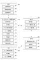
- processing executed in the communication system according to the present embodiment will be described with reference to the sequence diagram of FIG.
- a processing method for changing the slice allocation based on the resource status at a predetermined timing will be described. It is assumed that a service is assigned to a slice in advance.
- the resource acquisition unit 14 of the service mapping apparatus 10 transmits the slice ID and the function set of the slice to the NFVO 40, acquires the resource usage status, and updates the acquired result in the slice allocation table ( Step S1).
- the resource acquisition unit 14 refers to the slice allocation table and sends the resource usage status of each slice to the determination unit 15.
- the determination unit 15 determines whether there is a slice whose usage rate is tight. For example, as shown in FIG. 6, when the resource usage rate of the slice whose “NW Slice ID” in the slice allocation table is “1” is 80%, it is determined that the usage rate is tight. Since the slice is associated with a plurality of services (MBB, smartmeter), the determination unit 15 assigns any one service to another slice.
- the determination unit 15 sets the MBB as an allocation target service based on a predetermined priority order between service types.
- the determination unit 15 determines the slice to be allocated based on the SLA-SL of each slice and the usage status of the VM of the function set for each slice (step S2). Specifically, the determination unit 15 specifies a record in the slice requirement table having an SLA-SL that satisfies the SLA-SL of the service type stored in the service requirement table, and sets the resource in the slice indicated by the record. Decide to assign to the slice with the most free space. Since the slice with the slice ID 2 satisfies the SLA-SL of the service with the service type MBB, the determination unit 15 determines to allocate to the slice with the slice ID 2. The allocating unit 16 updates the slice allocation table so that the allocation target service type and the allocation destination slice are associated with each other.
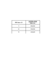
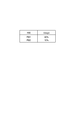
- FIG. 15 shows an example of information stored in the DNS server 80 when a service whose service type is MBB is assigned from a slice whose slice ID is 1 to a slice whose slice ID is 2.
- FIG. 15A is an example of information stored in the DNS server 80 before receiving a registration request from the service mapping apparatus 10.
- the service type “MBB” has a slice ID associated with 1. That is, it indicates that the slice with the slice ID 1 is assigned to the service type “MBB”.
- the registration request unit 17 transmits the service type “MBB” and the slice ID “2” to the DNS server 80 and requests the registration.
- the DNS server 80 changes the slice ID corresponding to the service type “MBB” to “2” and the IP corresponding to the service type “MBB”.
- the address is changed to “bb.bb.bb.bb” which is the IP address of slice ID2.
- the switch request unit 18 notifies the MME 90 of the service type and requests a switch (step S4).
- connection destination acquisition unit 92 transmits the service type to the DNS server 80 and requests acquisition of the connection destination information (step S5).
- the connection destination acquisition unit 92 of the MME 90 acquires the connection destination information (IP address) from the DNS server 80 (step S6: acquisition step).
- the connection control unit 93 of the MME 90 transmits the address of the eNB 100, the address of the PGW 120, the address of the connection destination SGW 110B, and the TEID (TunnelTEndpointTIDentifier) generated by the MME 90, and also to the connection destination device (SGW 110B).
- a session request is made (step S7).
- the SGW 110B transmits the IP address and TEID of the SGW 110B to the PGW 120B and makes a bearer update request (Modify bearer request) (step S8).
- the PGW 120B sends a response (Modify bearer response) to the SGW 110B (step S9).
- the SGW 110B When the SGW 110B receives a response from the PGW 120A, it transmits a response (Create session response) to the MME 90 (step S10). Thereby, downlink data flows (step S11).
- the connection control unit 93 of the MME 90 transmits the IP address and TEID of the SGW 110B to the eNB 100 and notifies the start of switching while receiving the above response as a trigger (step S12: notification step). Thereby, uplink data flows from UE130 to PGW120A (step S13).
- the connection control unit 93 of the MME 90 makes a notification of switching completion and a resource release request regarding the SGW 110A to the eNB 100 (step S14: release step). After the switch completion notification, the connection control unit 93 makes a session deletion request to the SGW 110A, receives the response by the session deletion, and ends the process (steps S15 and S16).
- the determination unit 15 of the service mapping apparatus 10 determines a slice having an SLA-SL corresponding to the service requirement (SLA-SL) of the service to be allocated (satisfying the service requirement).
- the assigning unit 16 assigns a service to the slice for which the service to be assigned is determined.
- the connection destination acquisition unit 92 acquires the address of the connection destination (SGW 110B) of the service to be allocated, and the connection control unit 93 notifies the eNB 100 of the IP address of the connection destination before releasing the resources related to the SGW 110A.
- the communication system notifies the eNB 100 of the SGW 110B that is the connection destination of the changed slice before determining the slice that matches the service requirement and before releasing the resources related to the SGW 110A that is the connection destination of the slice before the change. Therefore, it is possible to change the connection destination at the timing when the change of the slice occurs without performing the attach process from the eNB 100 side. That is, the service connection destination can be changed without interruption. As a result, the service can be used without instantaneous interruption.
- connection control unit 93 notifies the eNB 100 of the connection destination address after making a connection request to the service connection destination (SGW 110B).
- SGW 110B service connection destination
- the resource acquisition unit 14 acquires the resource status for each slice at a predetermined timing.
- the slice requirement acquisition unit 13 specifies the SLA-SL of each slice together with the service requirement of the service to which the slice has already been assigned.
- the determination unit 15 determines the slice to be allocated based on the service requirement of the service, the SLA-SL of each slice, and the resource status.
- the connection destination of the service can be dynamically allocated even when the resource status fluctuates.
- judgment used in this specification encompasses a wide variety of actions. “Judgment” can be, for example, calculating, computing, processing, deriving, investigating, looking up (eg, in a table, database, or another data structure Search), ascertaining, and the like. Also, “determining” can include receiving (eg, receiving information), accessing (eg, accessing data in a memory) and the like. Also, “determining” may include resolving, selecting, selecting, establishing, comparing, and the like.
- the phrase “based on” does not mean “based only on”, unless expressly specified otherwise. In other words, the phrase “based on” means both “based only on” and “based at least on.”
- notification of predetermined information is not limited to explicitly performed, but is performed implicitly (for example, notification of the predetermined information is not performed). Also good.
- SYMBOLS 10 Service mapping apparatus, 11 ... Request reception part, 12 ... Holding part, 13 ... Slice requirement acquisition part, 14 ... Resource acquisition part, 15 ... Determination part, 16 ... Assignment part, 17 ... Registration request part, 20 ... SO, 30 ... OSS / BSS, 40 ... NFVO, 41 ... holding unit, 42 ... resource request receiving unit, 43 ... resource notification unit, 50 ... VNFM, 51 ... configuration request receiving unit, 52 ... holding unit, 53 ... search unit, 60 ... VIM, 61 ... resource request receiving unit, 62 ... holding unit, 63 ... resource notifying unit, 70 ... HSS, 80 ... DNS server, 90 ... MME, 91 ...
- switch receiving unit 92 ... connection destination acquiring unit, 93 ... connection Control unit 100 ... eNB 101 ... CPU 102 ... RAM 103 ... ROM 104 ... communication module 105 ... auxiliary storage device 110 ... SGW 120 ... PGW 130 ... E, 160 ... NFVI.
Landscapes
- Engineering & Computer Science (AREA)
- Computer Networks & Wireless Communication (AREA)
- Signal Processing (AREA)
- Software Systems (AREA)
- Quality & Reliability (AREA)
- Theoretical Computer Science (AREA)
- Physics & Mathematics (AREA)
- General Engineering & Computer Science (AREA)
- General Physics & Mathematics (AREA)
- Data Exchanges In Wide-Area Networks (AREA)
- Mobile Radio Communication Systems (AREA)
Abstract
Selon la présente invention, un dispositif de mappage de service (10) stocke un tableau d'attribution de tranche qui associe les uns aux autres un service auquel une tranche a déjà été attribuée, la tranche correspondante et une adresse indiquant un dispositif qui exécute le service. En outre, une unité d'acceptation de demande (11) du dispositif de mappage de service (10) reçoit une exigence de niveau de service-niveau de service (SLA-SL) qui est une exigence de fonction. Une unité de détermination (15) détermine une tranche ayant une SLA-SL correspondant à une exigence de service (SLA-SL) du service à attribuer. Une unité d'attribution (16) change l'attribution du service à la tranche pour laquelle le service à attribuer a été déterminé. Une unité d'acquisition de destination de connexion (92) acquiert une adresse d'une destination de connexion (SGW 110B) du service à attribuer, et une unité de commande de connexion (93) notifie à un eNB (100) de l'adresse de la destination de connexion avant qu'une ressource se rapportant à une destination de connexion (SGW 110A) ne soit libérée.
Priority Applications (3)
| Application Number | Priority Date | Filing Date | Title |
|---|---|---|---|
| EP17775471.0A EP3439251A4 (fr) | 2016-04-01 | 2017-03-30 | Procédé de changement de tranche et dispositif de changement de tranche |
| US16/090,419 US10715404B2 (en) | 2016-04-01 | 2017-03-30 | Slice changing method and slice changing device |
| JP2018509469A JPWO2017170937A1 (ja) | 2016-04-01 | 2017-03-30 | スライス変更方法及びスライス変更装置 |
Applications Claiming Priority (2)
| Application Number | Priority Date | Filing Date | Title |
|---|---|---|---|
| JP2016-074245 | 2016-04-01 | ||
| JP2016074245 | 2016-04-01 |
Publications (1)
| Publication Number | Publication Date |
|---|---|
| WO2017170937A1 true WO2017170937A1 (fr) | 2017-10-05 |
Family
ID=59965992
Family Applications (1)
| Application Number | Title | Priority Date | Filing Date |
|---|---|---|---|
| PCT/JP2017/013409 Ceased WO2017170937A1 (fr) | 2016-04-01 | 2017-03-30 | Procédé de changement de tranche et dispositif de changement de tranche |
Country Status (4)
| Country | Link |
|---|---|
| US (1) | US10715404B2 (fr) |
| EP (1) | EP3439251A4 (fr) |
| JP (1) | JPWO2017170937A1 (fr) |
| WO (1) | WO2017170937A1 (fr) |
Cited By (5)
| Publication number | Priority date | Publication date | Assignee | Title |
|---|---|---|---|---|
| CN109067579A (zh) * | 2018-08-01 | 2018-12-21 | 重庆邮电大学 | 面向底层节点失效的5g网络切片拓扑设计及可靠映射方法 |
| WO2019073638A1 (fr) * | 2017-10-13 | 2019-04-18 | 株式会社Nttドコモ | Dispositif de production d'informations de sous-réseau et procédé de production d'informations de sous-réseau |
| JP2021191004A (ja) * | 2020-05-30 | 2021-12-13 | 華為技術有限公司Huawei Technologies Co., Ltd. | ネットワークスライストポロジおよびデバイスを決定するための方法およびシステム |
| US11588701B2 (en) | 2020-05-30 | 2023-02-21 | Huawei Technologies Co., Ltd. | Method and system for determining network slice topology, and device |
| WO2023152868A1 (fr) * | 2022-02-10 | 2023-08-17 | 日本電信電話株式会社 | Dispositif de commande, procédé de commande et programme |
Families Citing this family (12)
| Publication number | Priority date | Publication date | Assignee | Title |
|---|---|---|---|---|
| US9571331B1 (en) * | 2012-11-21 | 2017-02-14 | Amazon Technologies, Inc. | Techniques for accessing local networks via a virtualized gateway |
| US10855645B2 (en) | 2015-01-09 | 2020-12-01 | Microsoft Technology Licensing, Llc | EPC node selection using custom service types |
| EP3287897B1 (fr) * | 2015-05-19 | 2024-07-03 | Huawei Technologies Co., Ltd. | Procédé d'accélération de matériel et dispositif pertinent |
| CN106851589B (zh) * | 2016-12-30 | 2019-02-19 | 北京小米移动软件有限公司 | 无线网络接入方法、装置及系统 |
| US11038841B2 (en) | 2017-05-05 | 2021-06-15 | Microsoft Technology Licensing, Llc | Methods of and systems of service capabilities exposure function (SCEF) based internet-of-things (IOT) communications |
| IL277298B2 (en) * | 2018-03-20 | 2025-03-01 | Affirmed Networks Inc | Systems and methods for network slicing |
| US11252042B2 (en) * | 2019-04-12 | 2022-02-15 | Huawei Technologies Co., Ltd. | Systems and methods for communication network customization |
| JP7512687B2 (ja) * | 2020-06-03 | 2024-07-09 | 富士フイルムビジネスイノベーション株式会社 | 通信制御装置、通信制御プログラム、及び通信制御システム |
| US11696098B2 (en) * | 2021-03-04 | 2023-07-04 | Hewlett Packard Enterprise Development Lp | Automatically influencing UE slice policies based on real time analysis |
| WO2022235560A1 (fr) * | 2021-05-03 | 2022-11-10 | Intel Corporation | Infrastructure de calcul et de communication centrée sur des données |
| JP7672276B2 (ja) * | 2021-05-11 | 2025-05-07 | 株式会社Kddi総合研究所 | 制御装置、リソース割当制御方法及びコンピュータプログラム |
| CN113556761B (zh) * | 2021-06-25 | 2024-03-22 | 中国联合网络通信集团有限公司 | 切片资源调整方法、系统、终端设备及存储介质 |
Family Cites Families (14)
| Publication number | Priority date | Publication date | Assignee | Title |
|---|---|---|---|---|
| US20090205046A1 (en) * | 2008-02-13 | 2009-08-13 | Docomo Communications Laboratories Usa, Inc. | Method and apparatus for compensating for and reducing security attacks on network entities |
| EP2478667B1 (fr) * | 2009-09-18 | 2019-11-27 | Nokia Solutions and Networks GmbH & Co. KG | Contrôleur de réseau virtuel |
| JP5633440B2 (ja) * | 2011-03-17 | 2014-12-03 | 富士通株式会社 | 情報処理装置、電力制御方法及び電力制御プログラム |
| US9483258B1 (en) * | 2011-04-27 | 2016-11-01 | Intuit Inc | Multi-site provisioning of resources to software offerings using infrastructure slices |
| WO2012176277A1 (fr) * | 2011-06-21 | 2012-12-27 | 富士通株式会社 | Dispositif de traitement d'informations, procédé de gestion de machines virtuelles et programme de gestion de machines virtuelles |
| JP5788294B2 (ja) * | 2011-11-08 | 2015-09-30 | 株式会社日立製作所 | ネットワークシステムの管理方法 |
| JP5954783B2 (ja) | 2012-08-27 | 2016-07-20 | 国立研究開発法人情報通信研究機構 | モバイルネットワーク |
| US9450823B2 (en) * | 2013-08-09 | 2016-09-20 | Nec Corporation | Hybrid network management |
| BR112017023037A2 (pt) * | 2015-06-01 | 2018-07-03 | Huawei Tech Co Ltd | aparelho e método para funções virtualizadas em planos de controle e de dados. |
| US20160353367A1 (en) * | 2015-06-01 | 2016-12-01 | Huawei Technologies Co., Ltd. | System and Method for Virtualized Functions in Control and Data Planes |
| US10506489B2 (en) * | 2015-09-18 | 2019-12-10 | Huawei Technologies Co., Ltd. | System and methods for network slice reselection |
| EP3331204A4 (fr) * | 2015-09-30 | 2018-08-29 | Ntt Docomo, Inc. | Procédé de détermination d'attribution de service |
| US10129894B2 (en) * | 2016-03-04 | 2018-11-13 | Huawei Technologies Co., Ltd. | Systems and methods for performing traffic engineering through network slices |
| US9961624B1 (en) * | 2017-02-09 | 2018-05-01 | T-Mobile Usa, Inc. | Network slice selection in wireless telecommunication networks |
-
2017
- 2017-03-30 WO PCT/JP2017/013409 patent/WO2017170937A1/fr not_active Ceased
- 2017-03-30 JP JP2018509469A patent/JPWO2017170937A1/ja active Pending
- 2017-03-30 US US16/090,419 patent/US10715404B2/en not_active Expired - Fee Related
- 2017-03-30 EP EP17775471.0A patent/EP3439251A4/fr not_active Withdrawn
Non-Patent Citations (1)
| Title |
|---|
| TSUYOSHI OGURA ET AL.: "Cho Bunsan Bunkatsu Hozon sareta Daiyoryo Contents no Sokuji Haishin System", NATIONAL INSTITUTE OF INFORMATION AND COMMUNICATIONS TECHNOLOGY KENKYU HOKOKU, vol. 61, no. 2, 9 December 2015 (2015-12-09), pages 97 - 105, XP009515918, ISSN: 0913-5685 * |
Cited By (9)
| Publication number | Priority date | Publication date | Assignee | Title |
|---|---|---|---|---|
| WO2019073638A1 (fr) * | 2017-10-13 | 2019-04-18 | 株式会社Nttドコモ | Dispositif de production d'informations de sous-réseau et procédé de production d'informations de sous-réseau |
| CN109067579A (zh) * | 2018-08-01 | 2018-12-21 | 重庆邮电大学 | 面向底层节点失效的5g网络切片拓扑设计及可靠映射方法 |
| CN109067579B (zh) * | 2018-08-01 | 2021-05-04 | 重庆邮电大学 | 面向底层节点失效的5g网络切片拓扑设计及可靠映射方法 |
| JP2021191004A (ja) * | 2020-05-30 | 2021-12-13 | 華為技術有限公司Huawei Technologies Co., Ltd. | ネットワークスライストポロジおよびデバイスを決定するための方法およびシステム |
| JP7210643B2 (ja) | 2020-05-30 | 2023-01-23 | 華為技術有限公司 | ネットワークスライストポロジおよびデバイスを決定するための方法およびシステム |
| US11588701B2 (en) | 2020-05-30 | 2023-02-21 | Huawei Technologies Co., Ltd. | Method and system for determining network slice topology, and device |
| WO2023152868A1 (fr) * | 2022-02-10 | 2023-08-17 | 日本電信電話株式会社 | Dispositif de commande, procédé de commande et programme |
| JPWO2023152868A1 (fr) * | 2022-02-10 | 2023-08-17 | ||
| JP7662065B2 (ja) | 2022-02-10 | 2025-04-15 | 日本電信電話株式会社 | 制御装置、制御方法及びプログラム |
Also Published As
| Publication number | Publication date |
|---|---|
| JPWO2017170937A1 (ja) | 2019-02-21 |
| EP3439251A1 (fr) | 2019-02-06 |
| EP3439251A4 (fr) | 2019-08-28 |
| US20190116097A1 (en) | 2019-04-18 |
| US10715404B2 (en) | 2020-07-14 |
Similar Documents
| Publication | Publication Date | Title |
|---|---|---|
| WO2017170937A1 (fr) | Procédé de changement de tranche et dispositif de changement de tranche | |
| JP7061216B2 (ja) | スライス割当方法 | |
| US10356663B2 (en) | Service allocation determining methid | |
| JP6307172B2 (ja) | スライス管理システム及びスライス管理方法 | |
| JP6464257B2 (ja) | サービス割当決定装置及びサービス割当決定方法 | |
| JP6941613B2 (ja) | スライス管理システムおよびスライス管理方法 | |
| JP6307173B2 (ja) | システム及び方法 | |
| CN110352611B (zh) | 信息通知方法及移动通信系统 | |
| WO2018034156A1 (fr) | Procédé d'attribution de tranche | |
| JP6616957B2 (ja) | 通信システム及び通信方法 | |
| WO2018173815A1 (fr) | Procédé d'allocation de tranche et système de communication mobile | |
| WO2018180496A1 (fr) | Terminal de communication et procédé de commande de communication | |
| JP2018186450A (ja) | 通信制御方法 | |
| JP6932133B2 (ja) | スライス割当方法 |
Legal Events
| Date | Code | Title | Description |
|---|---|---|---|
| DPE1 | Request for preliminary examination filed after expiration of 19th month from priority date (pct application filed from 20040101) | ||
| WWE | Wipo information: entry into national phase |
Ref document number: 2018509469 Country of ref document: JP |
|
| NENP | Non-entry into the national phase |
Ref country code: DE |
|
| WWE | Wipo information: entry into national phase |
Ref document number: 2017775471 Country of ref document: EP |
|
| 121 | Ep: the epo has been informed by wipo that ep was designated in this application |
Ref document number: 17775471 Country of ref document: EP Kind code of ref document: A1 |