WO2017183152A1 - Dispositif d'imagerie et dispositif d'endoscopie - Google Patents
Dispositif d'imagerie et dispositif d'endoscopie Download PDFInfo
- Publication number
- WO2017183152A1 WO2017183152A1 PCT/JP2016/062630 JP2016062630W WO2017183152A1 WO 2017183152 A1 WO2017183152 A1 WO 2017183152A1 JP 2016062630 W JP2016062630 W JP 2016062630W WO 2017183152 A1 WO2017183152 A1 WO 2017183152A1
- Authority
- WO
- WIPO (PCT)
- Prior art keywords
- solid
- imaging
- imaging device
- state
- endoscope
- Prior art date
- Legal status (The legal status is an assumption and is not a legal conclusion. Google has not performed a legal analysis and makes no representation as to the accuracy of the status listed.)
- Ceased
Links
Images



Classifications
-
- A—HUMAN NECESSITIES
- A61—MEDICAL OR VETERINARY SCIENCE; HYGIENE
- A61B—DIAGNOSIS; SURGERY; IDENTIFICATION
- A61B1/00—Instruments for performing medical examinations of the interior of cavities or tubes of the body by visual or photographical inspection, e.g. endoscopes; Illuminating arrangements therefor
Definitions
- the present invention relates to an imaging apparatus provided with an image sensor for detecting a subject and an endoscope apparatus equipped with the imaging apparatus.
- An electronic device equipped with an imaging module for capturing an optical image that can be introduced from the outside of the living body or structure in order to observe difficult places such as the inside of the living body or the inside of the structure.
- Endoscopes are used, for example, in the medical field or the industrial field.
- An imaging apparatus for an electronic endoscope includes an objective lens that forms a subject image, and a solid-state imaging device that is an image sensor such as a CCD sensor or a CMOD sensor disposed on the imaging surface of the objective lens.
- Such an image pickup apparatus includes, for example, a vertically arranged structure in which a solid-state image pickup element described in Japanese Patent Application Laid-Open No. 2005-95432 is perpendicular to the photographing optical axis, A horizontal arrangement is known in which a solid-state imaging device is made parallel to a photographing optical axis by using a prism as described in Japanese Laid-Open Patent Publication.
- the hard length of the distal end portion of the insertion portion can be shortened, but the diameter is increased, and when placed horizontally, the distal end portion of the insertion portion is narrowed. Although the diameter can be increased, the hard length becomes longer, and there is a trade-off relationship.
- an object of the present invention is to provide an imaging apparatus and an endoscope that prevent an increase in size even when a solid-state imaging device becomes large due to an increase in the number of pixels. Is to provide a device.
- An imaging apparatus includes an optical system that forms a subject image, a solid-state imaging element that receives and photoelectrically converts the subject image formed by the optical system on a planar imaging surface, and the solid-state imaging A cover glass disposed on the front surface of the element, wherein the solid-state image sensor is disposed such that the image pickup surface has a predetermined angle that does not include orthogonal and parallel to the photographing optical axis of the optical system. In addition, all the side surfaces of the cover glass are parallel to the photographing optical axis.
- An endoscope apparatus includes an optical system that forms a subject image, a solid-state imaging element that receives and photoelectrically converts the subject image formed by the optical system on an imaging surface that is a plane, A cover glass disposed on a front surface of the solid-state imaging device, wherein the solid-state imaging device is disposed with a predetermined angle that the imaging surface does not include orthogonal and parallel to the imaging optical axis of the optical system.
- an imaging device in which all side surfaces of the cover glass are parallel to the imaging optical axis is mounted on the distal end portion of the insertion portion.
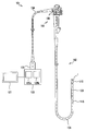
- the top view which shows the structure of the endoscope system which concerns on 1 aspect of this invention.
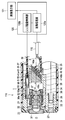
- tip part of an endoscope apparatus together with an external device and an image display part similarly
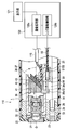
- tip part of the endoscope apparatus of the state which the movement lens holding frame moved back with the external apparatus and the image display part similarly
- tip part of an endoscope apparatus with the external apparatus and image display part of a 1st modification similarly.
- tip part of an endoscope apparatus with the external apparatus and image display part of a 2nd modification similarly.
- FIG. 1 is a perspective view showing a configuration of an endoscope system according to one embodiment of the present invention
- FIG. 2 is a view showing a cross section of a distal end portion of an endoscope apparatus together with an external apparatus and an image display section
- FIG. 3 is an external view. It is a figure which shows the cross section of the front-end
- An endoscope apparatus (hereinafter abbreviated as “endoscope”) 101 as an endoscope system of the present embodiment can be introduced into a subject such as a human body and optically transmits a predetermined observation site in the subject. It has a configuration for imaging.
- the subject into which the endoscope 101 is introduced is not limited to a human body, and may be another living body or an artificial object such as a machine or a building.
- the endoscope 101 includes an insertion portion 102 introduced into the subject, an operation portion 103 located at the proximal end of the insertion portion 102, and a universal cord 104 extending from a side portion of the operation portion 103. It is mainly composed.
- the insertion portion 102 includes a distal end portion 110 disposed at the distal end, a bendable bending portion 109 disposed on the proximal end side of the distal end portion 110, and an operation portion 103 disposed on the proximal end side of the bending portion 109.
- a flexible tube portion 108 having flexibility is connected to the tip end side of the tube.
- the endoscope 101 may have a form called a so-called rigid endoscope that does not include a flexible portion in the insertion portion 102.
- the distal end portion 110 is provided with an imaging device 1 described later.
- the operation unit 103 is provided with an angle operation knob 106 for operating the bending of the bending unit 109.
- an endoscope connector 105 connected to the external device 120 is provided.
- the external device 120 to which the endoscope connector 105 is connected is connected to an image display unit 121 such as a monitor via a cable.
- the imaging cable 115 is configured to electrically connect the endoscope connector 105 and the imaging device 1. By connecting the endoscope connector 105 to the external device 120, the imaging device 1 is electrically connected to the external device 120 via the imaging cable 115.
- the power supply from the external device 120 to the imaging device 1 and the communication between the external device 120 and the imaging device 1 are performed via the imaging cable 115.
- the external device 120 is provided with an image processing unit 120a and a lens drive control unit 120b.
- the image processing unit 120 a generates a video signal based on the image sensor output signal output from the imaging device 1 and outputs the video signal to the image display unit 121.
- an optical image (endoscopic image) captured by the imaging device 1 is displayed on the image display unit 121 as a video.
- the lens drive control unit 120b drives and controls an actuator for driving a movable lens (described later) provided in the imaging apparatus 1.
- the lens drive control unit 120b is connected to an air tube (not shown here) as a control cable described later inserted into the universal cord 104, the operation unit 103, and the insertion unit 102.
- the endoscope 101 is not limited to the configuration connected to the external device 120 or the image display unit 121, and may be configured to include a part or all of the image processing unit or the monitor, for example.
- an illumination window (not shown), which will be described later, is provided at the distal end portion 110, and an LED illumination (not shown), for example, is used as a light source here on the back side of the illumination window. Is arranged.
- the illumination means of the endoscope 101 is not limited to LED illumination, but employs an illumination optical fiber (light guide bundle) to transmit illumination light from a light source unit provided in the external device 120. It is good also as a structure.
- the configuration of the distal end portion 110 provided in the insertion portion 102 of the endoscope 101 will be described.
- the object side direction (left side in each figure) toward the subject may be referred to as the front end or the front, and the opposite image side direction may be referred to as the base end or the rear.
- the tip portion 110 is provided with a tip constituent portion 21 that is a metal block, and the imaging device 1 and the LED illumination 24 are fitted to the tip constituent portion 21.
- the distal end component 21 is provided with a distal end cover 22 that constitutes the distal end surface, and an illumination window 23 that emits illumination light of the observation window 31 and the LED illumination 24 of the imaging device 1 so as to be exposed by the distal end cover 22.
- These optical systems are arranged.
- a reinforcing frame 26 is fitted to the outer peripheral portion of the proximal end of the distal end constituting portion 21, and an outer skin 27 that covers the distal end constituting portion 21 together with the reinforcing frame 26 is disposed.
- the LED illumination 24 is fitted to the tip constituting portion 21 on the back side of the illumination window 23 via the LED holding frame 28.
- a wiring 25 for supplying power is extended from the LED illumination 24.
- the wiring 25 is inserted into the insertion unit 102, the operation unit 103, and the universal cord 104, and is disposed up to the endoscope connector 105.
- the LED illumination 24 is driven to turn on when electric power is supplied to the wiring 25 from the external device 120 to which the endoscope connector 105 is connected via the electrical contact of the endoscope connector 105.
- the imaging apparatus 1 includes a lens holding frame 32 that is a first fixed lens frame, a front group lens 33 that is configured by a plurality of objective optical systems that are held by the lens holding frame 32, and a lens. And a lens frame 34 that is a second fixed lens frame fitted to the holding frame 32.
- the imaging apparatus 1 is provided with a moving lens holding frame 36 that is a moving lens unit that moves back and forth within the lens frame 34, and a moving lens 37 that is an objective optical system is held on the moving lens holding frame 36. Yes.
- a solid-state image sensor holding frame 38 is fitted behind the lens frame 34, and a solid-state image sensor 40 such as a CCD or CMOS is fixed to a cover glass 41 held by the solid-state image sensor holding frame 38. Has been.
- the solid-state image sensor 40 is electrically connected to an image sensor substrate 42 on which electronic components and the like are mounted.
- An image pickup cable in which a plurality of wires as external signal lines are connected to the image sensor substrate 42 and the plurality of wires are collected. 115 extends rearward.
- the imaging cable 115 is electrically connected to the external device 120 via the endoscope connector 105 (see FIG. 1, not shown in FIG. 2), and the imaging signal photoelectrically converted by the solid-state imaging device 40 is inside the external device 120. To the image processing unit.
- a tubular member is fitted behind the solid-state image sensor holding frame 38, and a heat shrinkable tube is covered so as to cover the distal end portion of the imaging cable 115 together with the tubular member.
- a heat shrinkable tube is covered so as to cover the distal end portion of the imaging cable 115 together with the tubular member.
- the rear base end surface of the cover glass 41 is cut at a predetermined angle ⁇ of about 30 ° to 60 ° with respect to the photographing optical axis O, and the base end surface serves as an imaging surface of the solid-state imaging device 40.
- the light receiving surface 43 is bonded with a transparent resin.
- the solid-state imaging device 40 is disposed such that the light receiving surface 43 is tilted at a predetermined angle ⁇ of about 30 ° to 60 ° that does not include vertical (orthogonal) and horizontal (parallel) with respect to the photographing optical axis O.
- the predetermined angle ⁇ is set to 45 °.
- the upper surface 41 a and the lower surface 41 b that are the side surfaces of the cover glass 41 and the upper surface 40 a and the lower surface 40 b that are the side surfaces of the solid-state imaging device 40 have surfaces parallel to the imaging optical axis O.
- the cover glass 41 and the side surface of the solid-state imaging device 40 parallel to the photographing optical axis O.
- the glass 41 and the solid-state image sensor 40 are not damaged by the side surfaces, and the shooting angle of view is not narrowed.
- the cover glass 41 has all side surfaces around the photographing optical axis O parallel to the photographing optical axis O.
- the imaging apparatus 1 of the present embodiment is provided with an actuator 50 that drives the moving lens holding frame 36 forward and backward.
- the actuator 50 is an air cylinder held by an actuator holding frame 55 fixed to the solid-state image sensor holding frame 38, and is disposed in the cylinder tube 51, the piston rod 52, and the cylinder tube 51. And a piston 53 connected to the rod base end of the rod.
- the piston rod 52 is configured to be able to advance and retreat together with the piston 53 in the cylinder tube 51, and the rod tip is connected to an arm portion 36a protruding from a part of the outer periphery of the moving lens holding frame 36 by press fitting, screwing or the like.
- the arm portion 36a is engaged in a groove portion 55a formed in the actuator holding frame 55, and is guided straight when the moving lens holding frame 36 moves forward and backward.
- An air tube 56 is connected to the base end of the cylinder tube 51, and compressed air is taken in and out through the air tube 56.
- the air tube 56 is inserted into the insertion portion 102, the operation portion 103, and the universal cord 104, and is disposed up to the endoscope connector 105.
- the air tube 56 is connected to the external device 120 via the endoscope connector 105, and compressed air is input / output (supply / exhaust) from the lens drive control unit 120b provided with a compressor, an electromagnetic valve, and the like.
- the actuator 50 increases and reduces the pressure in the cylinder pipe 51, so that the piston 53 moves back and forth, and drives the moving lens holding frame 36 connected to the piston rod 52 back and forth.
- the actuator 50 has a distance range calculated by a cosine function of the predetermined angle ⁇ of the solid-state imaging device 40 and the length of the inclined light receiving surface 43 in the vertical direction (Lcos ⁇ when the length L of the light receiving surface 43 is assumed). Then, the movable lens holding frame 36 is driven forward and backward.
- the actuator 50 is driven and controlled in accordance with the reading timing of the subject image received by the solid-state imaging device 40, as shown in FIGS. .
- the solid-state imaging device 40 inclined at a predetermined angle ⁇ with respect to the photographing optical axis O of the subject reads light received by the light receiving surface 43 by a horizontal charge transfer method.
- the charges of one or a plurality of columns of pixels read out by the solid-state imaging device 40 are sequentially input as imaging signals through the imaging device substrate 42.
- a control signal is output from the image processing unit 120a to the lens drive control unit 120b. Based on this control signal, compressed air is sucked and exhausted by the lens drive control unit 120b, and the movable lens holding frame 36 is driven back and forth by a predetermined distance by the actuator 50.
- the actuator 50 is driven and controlled in accordance with the timing at which the charges of pixels in one column or a predetermined plurality of columns read out by the solid-state imaging device 40 are read out.
- the image processing unit 120 a accumulates sequentially input charges, synthesizes pixels in all areas of the light receiving surface 43 of the solid-state imaging device 40, generates a subject image, and outputs the subject image to the image display unit 121.
- the solid-state imaging device 40 tilted at a predetermined angle ⁇ with respect to the photographic optical axis O of the subject simultaneously collects charges obtained by photoelectrically converting all areas of the light receiving surface 43 that is one frame. And output as an imaging signal to the image processing unit 120a.
- a control signal is input from the image processing unit 120a to the lens drive control unit 120b. Based on this control signal, compressed air is taken in and out by the lens drive control unit 120b. Thus, the moving lens holding frame 36 is driven back and forth by a predetermined distance by the actuator 50.
- the actuator 50 is driven and controlled in accordance with the timing when the charges of the pixels in all areas read by the solid-state imaging device 40 are read.
- the image processing unit 120a accumulates a plurality of images based on the input imaging signal, cuts out (extracts) a focused portion from the plurality of images, and obtains one subject image. Generated and output to the image display unit 121.
- the moving lens holding frame 36 need not be driven many times because only one subject image needs to be acquired.
- a switch for switching between the moving image mode and the still image mode may be provided in the operation unit 103 of the endoscope 101.
- the imaging apparatus 1 is large in size due to an increase in the number of pixels and the like by providing the solid-state imaging device 40 with a predetermined angle ⁇ with respect to the imaging optical axis O of the subject. Even when the solid-state imaging device 40 is mounted, the enlargement in the outer diameter direction and the longitudinal axis direction (direction along the photographing optical axis O) is prevented as compared with the conventional structure such as the vertical installation or the horizontal installation. can do.
- the distal end portion 110 of the insertion portion 102 of the endoscope 101 on which the imaging apparatus 1 is mounted can be prevented from becoming a large diameter or the hard length can be increased, and the distal end portion 110 can be increased in size. Can be prevented.
- all the side surfaces including the upper surface 41a and the lower surface 41b of the cover glass 41 and the upper surface 40a and the lower surface 40b of the solid-state imaging device 40 arranged with a predetermined angle ⁇ are provided. Since the surface is parallel to the photographing optical axis O, the light receiving surface 43 of the solid-state imaging device 40 can make the most effective use of the region (area) where reflected light (photographing light) from the subject can be received. can do.
- the light rays in the peripheral portion among the light rays related to the formation of the subject image can be cast by the cover glass 41.
- the shooting angle of view is not narrowed.
- the actuator 50 illustrated the structure of the air cylinder, it is not limited to this, A liquid is used instead of compressed air, a servo motor, a stepping motor, a linear motor, a hydraulic cylinder, an electrostatic actuator, a piezoelectric
- a liquid is used instead of compressed air, a servo motor, a stepping motor, a linear motor, a hydraulic cylinder, an electrostatic actuator, a piezoelectric
- it can be diverted as long as it uses elements, shape memory alloys, or the like, or drives the movable lens holding frame 36 forward and backward.
- FIG. 4 is a diagram illustrating a cross-section of the distal end portion of the endoscope apparatus together with the external device and the image display unit of the first modified example.
- cover glass 41 may have a plate shape having a predetermined uniform width dimension in which the upper surface 41a and the lower surface 41b have surfaces parallel to the photographing optical axis O, as shown in FIG.
- FIG. 5 is a diagram showing a cross section of the distal end portion of the endoscope apparatus together with the external device and the image display unit of the second modified example
- FIG. 6 is a solid-state imaging together with the external device and the image display unit of the second modified example. It is a figure which shows the cross section of the front-end
- the imaging apparatus 1 of the present modification is configured to advance and retract a solid-state image sensor holding frame 38 that holds the solid-state image sensor 40 and the like by an actuator 50.
- the solid-state image sensor holding frame 38 here is disposed in the lens frame 34 so as to be able to advance and retract.
- the actuator 50 is connected by press-fitting, screwing, or the like to the arm portion 38a protruding from a part of the outer periphery of the solid-state image sensor holding frame 38 at the rod end of the piston rod 52.
- the arm portion 38a is engaged in a groove portion 34a formed in the lens frame 34, and is guided straight when the solid-state image sensor holding frame 38 moves forward and backward.
- the actuator 50 drives the solid-state image sensor holding frame 38 connected to the piston rod 52 back and forth by increasing and decreasing the pressure in the cylinder tube 51 by sending and discharging compressed air from the lens drive control unit 120b.
- the actuator 50 has a distance range calculated by a cosine function of the predetermined angle ⁇ of the solid-state imaging device 40 and the length of the inclined light receiving surface 43 in the vertical direction (Lcos ⁇ when the length L of the light receiving surface 43 is assumed). Then, the solid-state image sensor holding frame 38 is driven back and forth.
- the actuator 50 is driven and controlled in accordance with the reading timing of the subject image received by the solid-state imaging device 40, and the subject image is output from the image processing unit 120a to the image display unit 121.
- the configuration of such an imaging apparatus 1 can also be configured to have the same operational effects as the above-described embodiment.
- FIG. 7 is a schematic diagram illustrating a solid-state imaging device with respect to the depth of field and the depth of focus in the objective optical system according to the third modification.
- a moving lens holding frame 36 that holds the moving lens 37 or a solid-state imaging device holding frame 38 that holds the solid-state imaging device 40 is newly provided. There is no need to drive back and forth, and it is only necessary to provide the solid-state imaging device 40 having a predetermined angle ⁇ with respect to the imaging optical axis O of the subject.
- the described requirements can be deleted if the stated problem can be solved and the stated effect can be obtained.
- the configuration can be extracted as an invention.
Landscapes
- Health & Medical Sciences (AREA)
- Life Sciences & Earth Sciences (AREA)
- Surgery (AREA)
- Nuclear Medicine, Radiotherapy & Molecular Imaging (AREA)
- Biomedical Technology (AREA)
- Optics & Photonics (AREA)
- Pathology (AREA)
- Radiology & Medical Imaging (AREA)
- Biophysics (AREA)
- Engineering & Computer Science (AREA)
- Physics & Mathematics (AREA)
- Heart & Thoracic Surgery (AREA)
- Medical Informatics (AREA)
- Molecular Biology (AREA)
- Animal Behavior & Ethology (AREA)
- General Health & Medical Sciences (AREA)
- Public Health (AREA)
- Veterinary Medicine (AREA)
- Endoscopes (AREA)
Abstract
L'invention concerne un dispositif d'imagerie 1 comprenant : des systèmes optiques 33, 37 produisant l'image d'un objet ; un élément d'imagerie à semi-conducteurs 40 recevant l'image de l'objet produite par les systèmes optiques 33, 37 sur une surface d'imagerie plane 43 et réalisant une conversion photoélectrique ; et un verre de couverture 41 disposé sur la face avant de l'élément d'imagerie à semi-conducteurs 40. L'élément d'imagerie à semi-conducteurs 40 est disposé de telle sorte que la surface d'imagerie 43 soit orientée selon un angle prédéterminé qui n'englobe pas les angles droit et parallèle par rapport à l'axe optique d'imagerie des systèmes optiques 33, 37. Toutes les faces latérales 41a, 41b du verre de couverture 41 sont parallèles à l'axe optique d'imagerie O.
Priority Applications (1)
| Application Number | Priority Date | Filing Date | Title |
|---|---|---|---|
| PCT/JP2016/062630 WO2017183152A1 (fr) | 2016-04-21 | 2016-04-21 | Dispositif d'imagerie et dispositif d'endoscopie |
Applications Claiming Priority (1)
| Application Number | Priority Date | Filing Date | Title |
|---|---|---|---|
| PCT/JP2016/062630 WO2017183152A1 (fr) | 2016-04-21 | 2016-04-21 | Dispositif d'imagerie et dispositif d'endoscopie |
Publications (1)
| Publication Number | Publication Date |
|---|---|
| WO2017183152A1 true WO2017183152A1 (fr) | 2017-10-26 |
Family
ID=60115888
Family Applications (1)
| Application Number | Title | Priority Date | Filing Date |
|---|---|---|---|
| PCT/JP2016/062630 Ceased WO2017183152A1 (fr) | 2016-04-21 | 2016-04-21 | Dispositif d'imagerie et dispositif d'endoscopie |
Country Status (1)
| Country | Link |
|---|---|
| WO (1) | WO2017183152A1 (fr) |
Citations (2)
| Publication number | Priority date | Publication date | Assignee | Title |
|---|---|---|---|---|
| JPS63149620A (ja) * | 1986-12-15 | 1988-06-22 | Olympus Optical Co Ltd | 電子内視鏡用光学系 |
| JPH0220817A (ja) * | 1988-04-11 | 1990-01-24 | Olympus Optical Co Ltd | 内視鏡装置 |
-
2016
- 2016-04-21 WO PCT/JP2016/062630 patent/WO2017183152A1/fr not_active Ceased
Patent Citations (2)
| Publication number | Priority date | Publication date | Assignee | Title |
|---|---|---|---|---|
| JPS63149620A (ja) * | 1986-12-15 | 1988-06-22 | Olympus Optical Co Ltd | 電子内視鏡用光学系 |
| JPH0220817A (ja) * | 1988-04-11 | 1990-01-24 | Olympus Optical Co Ltd | 内視鏡装置 |
Similar Documents
| Publication | Publication Date | Title |
|---|---|---|
| KR100852310B1 (ko) | 내시경 및 내시경 시스템 | |
| JP5318142B2 (ja) | 電子内視鏡 | |
| US10084947B2 (en) | Imaging module | |
| JP6042998B2 (ja) | 光学ユニットおよびこの光学ユニットを備えた内視鏡 | |
| US10708553B2 (en) | Measurement support device, endoscope system, processor for endoscope system | |
| US20130182099A1 (en) | Photoelectric conversion connector, optical transmission module, imaging apparatus, and endoscope | |
| US12034904B2 (en) | Endoscopic imaging systems for generating three dimensional images, and associated systems and methods | |
| JP6253857B1 (ja) | 立体内視鏡および立体内視鏡システム | |
| US8305486B2 (en) | Auto-focus intra-oral camera having a linear piezoelectric actuator | |
| WO2015166750A1 (fr) | Unité optique, endoscope équipé de celle-ci | |
| US10478049B2 (en) | Endoscope | |
| JP3001035B2 (ja) | 内視鏡用光学アダプタ | |
| WO2014188787A1 (fr) | Structure d'extrémité d'endoscope et endoscope | |
| JP2015112336A (ja) | 内視鏡システム | |
| WO2017183152A1 (fr) | Dispositif d'imagerie et dispositif d'endoscopie | |
| JP3875291B2 (ja) | 電子内視鏡 | |
| KR20150056241A (ko) | 내시경 장치 | |
| KR102314027B1 (ko) | 영상촬영장치 | |
| JP3791763B2 (ja) | 内視鏡 | |
| JPH08201706A (ja) | 内視鏡装置 | |
| JP6573280B2 (ja) | 内視鏡 | |
| JP2000258698A (ja) | 立体視内視鏡 | |
| US20210085166A1 (en) | Endoscope | |
| JP2017196171A (ja) | 撮像ユニット及び内視鏡 | |
| WO2021210089A1 (fr) | Dispositif d'imagerie, endoscope et partie pointe d'endoscope |
Legal Events
| Date | Code | Title | Description |
|---|---|---|---|
| NENP | Non-entry into the national phase |
Ref country code: DE |
|
| 121 | Ep: the epo has been informed by wipo that ep was designated in this application |
Ref document number: 16899424 Country of ref document: EP Kind code of ref document: A1 |
|
| 122 | Ep: pct application non-entry in european phase |
Ref document number: 16899424 Country of ref document: EP Kind code of ref document: A1 |
|
| NENP | Non-entry into the national phase |
Ref country code: JP |