WO2017187563A1 - Bâtiment de turbine et centrale nucléaire - Google Patents
Bâtiment de turbine et centrale nucléaire Download PDFInfo
- Publication number
- WO2017187563A1 WO2017187563A1 PCT/JP2016/063231 JP2016063231W WO2017187563A1 WO 2017187563 A1 WO2017187563 A1 WO 2017187563A1 JP 2016063231 W JP2016063231 W JP 2016063231W WO 2017187563 A1 WO2017187563 A1 WO 2017187563A1
- Authority
- WO
- WIPO (PCT)
- Prior art keywords
- turbine
- earthquake resistant
- building
- high earthquake
- turbine housing
- Prior art date
- Legal status (The legal status is an assumption and is not a legal conclusion. Google has not performed a legal analysis and makes no representation as to the accuracy of the status listed.)
- Ceased
Links
Images


Classifications
-
- E—FIXED CONSTRUCTIONS
- E04—BUILDING
- E04H—BUILDINGS OR LIKE STRUCTURES FOR PARTICULAR PURPOSES; SWIMMING OR SPLASH BATHS OR POOLS; MASTS; FENCING; TENTS OR CANOPIES, IN GENERAL
- E04H9/00—Buildings, groups of buildings or shelters adapted to withstand or provide protection against abnormal external influences, e.g. war-like action, earthquake or extreme climate
- E04H9/02—Buildings, groups of buildings or shelters adapted to withstand or provide protection against abnormal external influences, e.g. war-like action, earthquake or extreme climate withstanding earthquake or sinking of ground
-
- E—FIXED CONSTRUCTIONS
- E04—BUILDING
- E04H—BUILDINGS OR LIKE STRUCTURES FOR PARTICULAR PURPOSES; SWIMMING OR SPLASH BATHS OR POOLS; MASTS; FENCING; TENTS OR CANOPIES, IN GENERAL
- E04H5/00—Buildings or groups of buildings for industrial or agricultural purposes
- E04H5/02—Buildings or groups of buildings for industrial purposes, e.g. for power-plants or factories
-
- G—PHYSICS
- G21—NUCLEAR PHYSICS; NUCLEAR ENGINEERING
- G21D—NUCLEAR POWER PLANT
- G21D1/00—Details of nuclear power plant
- G21D1/02—Arrangements of auxiliary equipment
-
- F—MECHANICAL ENGINEERING; LIGHTING; HEATING; WEAPONS; BLASTING
- F01—MACHINES OR ENGINES IN GENERAL; ENGINE PLANTS IN GENERAL; STEAM ENGINES
- F01K—STEAM ENGINE PLANTS; STEAM ACCUMULATORS; ENGINE PLANTS NOT OTHERWISE PROVIDED FOR; ENGINES USING SPECIAL WORKING FLUIDS OR CYCLES
- F01K7/00—Steam engine plants characterised by the use of specific types of engine; Plants or engines characterised by their use of special steam systems, cycles or processes; Control means specially adapted for such systems, cycles or processes; Use of withdrawn or exhaust steam for feed-water heating
- F01K7/16—Steam engine plants characterised by the use of specific types of engine; Plants or engines characterised by their use of special steam systems, cycles or processes; Control means specially adapted for such systems, cycles or processes; Use of withdrawn or exhaust steam for feed-water heating the engines being only of turbine type
- F01K7/22—Steam engine plants characterised by the use of specific types of engine; Plants or engines characterised by their use of special steam systems, cycles or processes; Control means specially adapted for such systems, cycles or processes; Use of withdrawn or exhaust steam for feed-water heating the engines being only of turbine type the turbines having inter-stage steam heating
- F01K7/223—Inter-stage moisture separation
-
- F—MECHANICAL ENGINEERING; LIGHTING; HEATING; WEAPONS; BLASTING
- F22—STEAM GENERATION
- F22B—METHODS OF STEAM GENERATION; STEAM BOILERS
- F22B1/00—Methods of steam generation characterised by form of heating method
- F22B1/02—Methods of steam generation characterised by form of heating method by exploitation of the heat content of hot heat carriers
- F22B1/023—Methods of steam generation characterised by form of heating method by exploitation of the heat content of hot heat carriers with heating tubes for nuclear reactors, as long as they are not classified according to a specified heating fluid, in another group
-
- G—PHYSICS
- G21—NUCLEAR PHYSICS; NUCLEAR ENGINEERING
- G21C—NUCLEAR REACTORS
- G21C13/00—Pressure vessels; Containment vessels; Containment in general
-
- Y—GENERAL TAGGING OF NEW TECHNOLOGICAL DEVELOPMENTS; GENERAL TAGGING OF CROSS-SECTIONAL TECHNOLOGIES SPANNING OVER SEVERAL SECTIONS OF THE IPC; TECHNICAL SUBJECTS COVERED BY FORMER USPC CROSS-REFERENCE ART COLLECTIONS [XRACs] AND DIGESTS
- Y02—TECHNOLOGIES OR APPLICATIONS FOR MITIGATION OR ADAPTATION AGAINST CLIMATE CHANGE
- Y02E—REDUCTION OF GREENHOUSE GAS [GHG] EMISSIONS, RELATED TO ENERGY GENERATION, TRANSMISSION OR DISTRIBUTION
- Y02E30/00—Energy generation of nuclear origin
Definitions
- the present invention relates to a turbine building that houses a steam turbine and the like, and a nuclear power plant including the turbine building.
- a nuclear power plant is composed of a nuclear reactor, a steam generator, a steam turbine, a generator, and the like.
- the primary coolant is heated by nuclear fission in the reactor, and the high-temperature primary coolant is sent to the steam generator, where heat exchange is performed between the high-temperature primary coolant and the secondary coolant. Crack steam is generated.
- the generated steam (secondary coolant) is sent to the steam turbine and driven, and the connected generator is driven to generate power.
- the reactor building and the turbine building are installed adjacent to each other.
- the reactor building has a reactor containment vessel in which a reactor and a steam generator are stored.
- a steam turbine or the like is disposed inside.
- the reactor building is a seismic design building, while the turbine building is a general design building. Examples of such nuclear power plants include those described in the following patent documents.
- the reactor building is a seismic design building and the turbine building is a general design building, but the impact on the reactor building due to the collapse of this turbine building is considered.
- the turbine building may be a seismic design building.
- the turbine building is also a seismic design building, there is a problem that the construction cost increases.
- This invention solves the subject mentioned above, and it aims at providing the turbine building and nuclear power plant which suppress the increase in construction cost, maintaining high safety
- a turbine building according to the present invention includes a turbine housing portion in which a steam turbine is housed, and a high earthquake-resistant portion that is close to the turbine housing portion and has higher earthquake resistance than the turbine housing portion.
- the turbine housing part and the high earthquake resistant part are characterized in that the internal spaces thereof communicate with each other and form independent structures.
- the operator can easily move between the turbine housing portion and the high earthquake resistant portion during normal operation of the steam turbine. Since each structure is independent, when an earthquake occurs, even if the turbine housing part collapses, the collapse of the high earthquake resistant part is suppressed, and the impact of the collapse of the turbine housing part is mostly transmitted to the high earthquake resistant part. Absent. Therefore, the collapse of the turbine housing part does not affect the building adjacent to the high earthquake resistant part, and high safety can be maintained, and an increase in construction cost can be suppressed.
- the turbine building of the present invention is characterized in that the turbine housing part and the high earthquake resistant part are provided with independent foundations.
- the turbine housing part and the high earthquake resistant part are installed on independent foundations, when an earthquake occurs, the turbine housing part and the high earthquake resistant part are separately affected by the earthquake.
- the influence of the collapse of the turbine housing portion is hardly transmitted, and the collapse of the high earthquake resistant portion can be suppressed.
- the turbine building according to the present invention is characterized in that a gap is provided between the turbine housing part and the high earthquake-resistant part between each other.
- the turbine building of the present invention is characterized in that a buffer member is disposed in the gap between the mutual structures in the turbine housing portion and the high earthquake resistant portion.
- the buffer member is arranged in the gap between the structural bodies of the turbine housing portion and the high earthquake resistant portion, vibration transmission can be suppressed between the turbine housing portion and the high earthquake resistant portion, and The gap between the turbine housing part and the high earthquake-resistant part is closed, and the internal space can be moved between the turbine housing part and the high earthquake-resistant part, and the maintainability can be improved.
- the turbine building according to the present invention is characterized in that the gap between the structures of the turbine housing part and the high earthquake resistant part is covered with a cover.
- the high seismic resistant part has at least one of the thickness of the pillar, the thickness of the wall and the floor, and the thickness of the beam, the thickness of the pillar of the turbine accommodating part, the thickness of the wall and floor, and the thickness of the beam. It is characterized by being set large.
- the high seismic resistance part can easily improve the seismic resistance of the high seismic resistance part because at least one of the column thickness, wall and floor thickness, and beam thickness is set larger than that of the turbine housing part. Can do.
- the high seismic resistant part is characterized in that the height is set lower than the height of the turbine accommodating part.
- the height of the high earthquake resistant part is set lower than the height of the turbine housing part, an increase in the construction cost of the high earthquake resistant part can be suppressed.
- the high earthquake-resistant portion is characterized in that the steam turbine related equipment is accommodated therein.
- the steam turbine-related equipment is accommodated in the high earthquake resistant part, the internal space of the high earthquake resistant part can be effectively utilized, and the accommodation equipment in the turbine accommodating part is reduced, thereby reducing the size of the turbine accommodating part. Can be planned.
- the turbine building according to the present invention is characterized in that the related equipment is arranged along a horizontal direction intersecting a parallel direction of the turbine housing portion and the high earthquake resistant portion.
- the related equipment is arranged along the horizontal direction intersecting the parallel direction of the turbine housing portion and the high earthquake resistant portion, the thickness in the horizontal direction of the high earthquake resistant portion is reduced to reduce the size of the high earthquake resistant portion. be able to.
- the nuclear power plant according to the present invention includes the turbine building, and a reactor building in which a nuclear reactor is accommodated and installed at a predetermined interval in the high seismic resistant portion in the turbine building. Is.
- the operator can easily move between the turbine housing portion and the high earthquake resistant portion during normal operation of the steam turbine. Since each structure is independent, when an earthquake occurs, even if the turbine housing part collapses, the collapse of the high earthquake resistant part is suppressed, and the impact of the collapse of the turbine housing part is mostly transmitted to the high earthquake resistant part. Absent. Therefore, the collapse of the turbine housing part does not affect the reactor building adjacent to the high earthquake resistant part, and high safety can be maintained and an increase in construction cost can be suppressed.
- the internal space of the turbine housing part and the high earthquake resistant part communicate with each other and form independent structures, so that high safety can be maintained and the construction cost can be maintained. Can be suppressed.
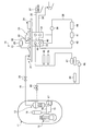
- FIG. 1 is a schematic configuration diagram illustrating a nuclear power plant according to the present embodiment.
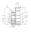
- FIG. 2 is a schematic diagram showing the relationship between the reactor building and the turbine building.
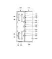
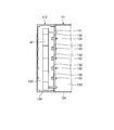
- 3 is a cross-sectional view taken along the line III-III in FIG. 4 is a cross-sectional view taken along the line IV-IV in FIG. 5 is a cross-sectional view taken along the line VV in FIG.
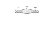
- FIG. 6 is a cross-sectional view illustrating a floor connecting portion in the turbine building.
- FIG. 7 is a cross-sectional view illustrating a wall connecting portion in the turbine building.
- FIG. 1 is a schematic configuration diagram showing a nuclear power plant according to the present embodiment.
- the nuclear reactor of the present embodiment uses light water as a reactor coolant and a neutron moderator, and produces high-temperature and high-pressure water that does not boil over the entire core, and sends this high-temperature and high-pressure water to a steam generator to generate steam by heat exchange.
- This is a pressurized water reactor (PWR) that sends this steam to a turbine generator to generate electricity.
- PWR pressurized water reactor
- BWR boiling water reactor
- a nuclear reactor containment vessel 11 stores therein a nuclear reactor (pressurized water reactor) 12 and a steam generator 13.
- the steam generator 13 is connected via pipes 14 and 15, a pressurizer 16 is provided in the pipe 14, and a primary cooling water pump 17 is provided in the pipe 15.
- light water is used as the moderator and the primary coolant, and the primary cooling system is controlled by the pressurizer 16 to maintain a high pressure state in order to suppress boiling of the primary cooling water in the core.
- the steam generator 13 is connected to a steam turbine 19 through a pipe 18, and a main steam isolation valve 20 is provided in the pipe 18.
- the steam turbine 19 includes a high-pressure turbine 21 and two low-pressure turbines 22 and 23, and a generator 24 is connected on the same axis.
- the high-pressure turbine 21 and the low-pressure turbines 22 and 23 are provided with a moisture separation heater 28 between them. That is, the pipe 18 from the steam generator 13 is connected to the inlet part of the high-pressure turbine 21, and the steam pipe 31 is connected from the outlet part of the high-pressure turbine 21 to the inlet part of the moisture separation heater 28, and moisture separation heating is performed.
- Steam pipes 32 are connected from the outlet of the vessel 28 to the inlets of the low-pressure turbines 22 and 23.
- the steam turbine 19 is provided with condensers 33 and 34 below the low-pressure turbines 22 and 23. These condensers 33 and 34 cool the steam used in the low-pressure turbines 22 and 23 with cooling water and condense it to form condensate. Seawater is applied as the cooling water, and the condensers 33 and 34 are connected to a water intake pipe 35 and a drain pipe 36 for supplying and discharging the cooling water.
- the intake pipe 35 has a circulating water pump 37 and the other end portion is disposed in the sea together with the drain pipe 36.
- the condensers 33 and 34 are connected to a pipe 38, and a condensate pump 39, a ground condenser 40, a condensate demineralizer 41, a condensate booster pump 42, and a low-pressure feed water heater 43 are connected to the pipe 38. , 44, 45, 46 are provided in order along the flow direction of the condensate.
- the first low-pressure feed water heater 43 and the second low-pressure feed water heater 44 are provided in the condensers 33 and 34, and the condensate is heated by the steam used in the low-pressure turbines 22 and 23.
- the third low-pressure feed water heater 45 and the fourth low-pressure feed water heater 46 are provided outside the condensers 33 and 34, and the condensate is heated by steam extracted from the low-pressure turbines 22 and 23.
- a deaerator 47 In the pipe 38, a deaerator 47, a main feed water pump 48, a high pressure feed water heater 49, and a main feed water control valve 50 are provided in order along the flow direction of the condensate downstream from the fourth low pressure feed water heater 46. ing.
- the steam generated by performing heat exchange with the high-temperature and high-pressure primary cooling water by the steam generator 13 is sent to the steam turbine 19 through the pipe 18, and the high-pressure turbine 21 and the low-pressure turbines 22 and 23 are operated. A rotational force is obtained, and the generator 24 is driven by this rotational force to generate power. At this time, after the steam from the steam generator 13 drives the high-pressure turbine 21, moisture contained in the steam is removed and heated by the moisture separation heater 28, and then the low-pressure turbines 22 and 23 are driven. To do.
- the steam that has driven the low-pressure turbines 22 and 23 is cooled using seawater in the condensers 33 and 34 to become condensate, flows through the pipe 38 by the condensate pump 39, and is connected to the ground condenser 40 and the condensate demineralizer. 41, the low pressure feed water heaters 43, 44, 45, 46, the deaerator 47, the high pressure feed water heater 49 and the like are returned to the steam generator 13.
- FIG. 2 is a schematic diagram showing the relationship between the reactor building and the turbine building
- FIG. 3 is a sectional view taken along the line III-III in FIG. 2
- FIG. 4 is a sectional view taken along the line IV-IV in FIG. 2
- FIG. 6 is a cross-sectional view showing a floor connecting portion in the turbine building
- FIG. 7 is a cross-sectional view showing a wall connecting portion in the turbine building.
- a reactor building 101 and a turbine building 102 are installed in a site at a predetermined interval.
- the reactor building 101 is a high earthquake resistant building by being seismically designed
- the turbine building 102 is a general building that is not designed to be a high earthquake resistant building by being generally designed.
- a reactor containment vessel 11 (see FIG. 1) is installed, and a reactor 12, a steam generator 13, a pressurizer 16, a primary cooling water pump 17, and the like are installed inside the reactor containment vessel 11. Stored.
- the turbine building 102 includes a turbine housing part 111 and a high earthquake resistant part 112.
- the turbine housing part 111 includes a steam turbine 19 (high pressure turbine 21 and low pressure turbines 22 and 23), a generator 24, a moisture separation heater 28, condensers 33 and 34, a condensate pump 39, a ground condenser 40, a condensate.
- a desalinator 41, a condensate booster pump 42, low-pressure feed water heaters 43, 44, 45, 46, and a main feed water pump 48 are accommodated.
- the high seismic resistant part 112 accommodates a deaerator 47 and a high-pressure feed water heater 49 which are related devices of the steam turbine 19.
- the turbine building 102 is a general building composed of a steel structure, and a plurality of pillars 122 are erected on a foundation 121, and are formed by a plurality of floors 123, a plurality of walls 124, and a ceiling 125.
- the high earthquake resistant portion 112 is an earthquake resistant building composed of a reinforced concrete structure, and a plurality of pillars 132 are erected on a foundation 131 and formed by a plurality of floors 133, a plurality of walls 134, and a ceiling 135. ing.
- the high seismic resistant part 112 is designed not to collapse when the seismic motion in the seismic design of the reactor building 101 is used as a reference.
- the turbine accommodating portion 111 is designed as a building having a lower earthquake resistance than the high earthquake resistant portion 112, that is, as a building having a lower earthquake resistance class than the high earthquake resistant portion 112.
- the turbine housing part 111 and the high earthquake-resistant part 112 communicate with each other and have independent structures. That is, the turbine housing part 111 and the high earthquake resistant part 112 are buildings installed on independent foundations 121 and 131, respectively, and the high earthquake resistant part 112 is a building having higher earthquake resistance than the turbine containing part 111. Yes.
- the high seismic resistant part 112 has the thickness of the pillar 132, the thickness of the floor 133, the thickness of the wall 134, the thickness of the ceiling 135, and the thickness of the beam (not shown) of the pillar 122 of the turbine accommodating part 111.
- the thickness is set larger than the thickness of the floor 123, the thickness of the wall 124, the thickness of the ceiling 125, and the thickness of the beam (not shown).
- the height of the high earthquake resistant portion 112 is set to be lower by one floor than the height of the turbine accommodating portion 111.
- the reactor building 101 and the high earthquake resistant part 112 in the turbine building 102 are installed apart from each other by a predetermined distance.
- the turbine housing part 111 and the high earthquake resistant part 112 are installed close to each other. That is, the turbine housing part 111 and the high earthquake resistant part 112 are provided with the foundations 121 and 131 in close contact with each other, but with the pillars 122 and 132, the floors 123 and 133, and the walls 124 and 134 as gaps. ing.
- the buffer member 141 is arrange
- a buffer member 141 is interposed between the end of the floor 123 in the turbine accommodating portion 111 and the end of the floor 133 in the high earthquake resistant portion 112, and the floors 123 and 133 are continuously connected. I am letting. Further, as shown in FIG. 7, the cover member 142 is fixed so as to close a gap between the end of the wall 124 in the turbine accommodating portion 111 and the end of the wall 134 in the high earthquake resistant portion 112, and the walls 124 and 134 are fixed.
- the outer surface is continuous.
- the high earthquake-resistant section 112 has a plurality of pumps 51 arranged on the first floor 133 and a plurality of high-pressure feed water heaters 49 arranged on the second floor 133.
- a deaerator 47 is arranged on the floor 133 of the floor.
- the deaerator 47 and the plurality of high-pressure feed water heaters 49 are arranged in the horizontal direction (FIGS. 4 and 4) intersecting the parallel direction (the left-right direction in FIGS. 1 to 4) of the turbine housing part 111 and the high earthquake resistant part 112. (Up and down direction) and connected to the steam turbine 19 on the turbine housing part 111 side by piping.
- the reactor building 101 and the turbine building 102 are installed adjacent to each other, and the high seismic resistant portion 112 is installed with a predetermined interval between the reactor building 101 and the turbine accommodating portion 111. It becomes.
- the turbine accommodating portion 111 and the high earthquake resistant portion 112 are independent structures, the internal space communicates with each other, so that the operator can move between the turbine accommodating portion 111 and the high earthquake resistant portion 112. It can be moved and maintenance of various devices is good.
- the turbine housing part 111 and the high earthquake-resistant part 112 are independent structures with different foundations 121 and 131, the turbine housing part 111 and the high earthquake-resistant part 112 vibrate independently when an earthquake occurs.
- the turbine accommodating part 111 and the high earthquake resistant part 112 are connected by the buffer member 141, the pillars 122 and 132, the floors 123 and 133, and the walls 124 and 134 are not directly connected, and one vibration is applied to the other. It is hardly transmitted.
- the turbine housing portion 111 collapses, the collapse of the high earthquake resistant portion 112 that is an earthquake resistant design is suppressed. And the influence of the collapse of the turbine accommodating part 111 is hardly transmitted to the high earthquake resistant part 112.
- the distance between the reactor building 101 and the high earthquake resistant portion 112 and the height of the high earthquake resistant portion 112 are such that even if the turbine accommodating portion 111 collapses to the high earthquake resistant portion 112 side, the damaged material is on the reactor building 101 side. Therefore, high safety of the reactor building 101 is maintained.
- the turbine housing part 111 and the high earthquake-resistant part 112 communicate with each other and have independent structures.
- the internal space of the turbine accommodating portion 111 and the high earthquake resistant portion 112 communicate with each other, an operator can easily move between the turbine accommodating portion 111 and the high earthquake resistant portion 112 during normal operation of the steam turbine 19. Therefore, operability and maintenance can be improved.
- the turbine accommodating part 111 and the high earthquake resistant part 112 make an independent structure, respectively, even if the turbine accommodating part 111 collapses when an earthquake occurs, the collapse of the high earthquake resistant part 112 is suppressed.
- the impact of the collapse of the turbine accommodating portion 111 is hardly transmitted to the high earthquake resistant portion 112.
- the collapse of the turbine accommodating portion 111 does not affect the reactor building 101 adjacent to the high seismic resistant portion 112, so that high safety can be maintained and an increase in construction cost can be suppressed.
- the turbine housing part 111 and the high earthquake resistant part 112 are installed on independent foundations 121 and 131, respectively. Therefore, when an earthquake occurs, the turbine housing part 111 and the high earthquake-resistant part 112 are separately affected by the earthquake, and the high earthquake-resistant part 112 is hardly affected by the collapse of the turbine housing part 111. The collapse of the earthquake-resistant part 112 can be suppressed.
- a gap is provided between the turbine housing part 11 and the structure in the high earthquake resistant part 112. Therefore, when an earthquake occurs, the vibration of the turbine housing portion 111 is hardly transmitted to the high earthquake resistant portion 112, and the collapse of the high earthquake resistant portion 112 can be suppressed.
- the buffer member 141 is arranged in the gap between the structural bodies in the turbine housing part 111 and the high earthquake-resistant part 12. Therefore, the transmission of vibration between the turbine housing part 111 and the high earthquake-resistant part 112 can be suppressed by the buffer member 141, and the gap between the turbine housing part 111 and the high earthquake-resistant part 112 is closed. It is possible to move the internal space between the housing part 111 and the high earthquake resistant part 112 and improve the maintainability.
- the cover member 142 covers the gaps between the structures in the turbine housing portion 111 and the high earthquake resistant portion 112. Therefore, the cover member 142 prevents rainwater and the like from entering the internal space of the turbine housing portion 111 and the high earthquake resistant portion 112, enabling the internal space of the turbine housing portion 11 and the high earthquake resistant portion 112 to be moved for effective use. be able to.
- the high seismic resistant part 112 includes at least one of the thickness of the pillar 132 and the wall 134 and the thickness of the floor 133 and the thickness of the beam, and the thickness of the pillar 122 of the turbine accommodating part 111 and the wall 124 and the floor.
- the thickness of 123 and the thickness of the beam are set larger. Therefore, the earthquake resistance of the high earthquake resistant portion 112 can be easily improved.
- the height of the high earthquake resistant portion 112 is set lower than the height of the turbine housing portion 111. Therefore, since the high seismic resistant part 112 and the reactor building 101 are separated from each other, when the turbine accommodating part 111 collapses, a part of the collapsed turbine accommodating part 111 is blocked by the high earthquake resistant part 112 and the reactor building 101 It is suppressed that it falls to the side. At this time, the height of the high earthquake resistant portion 112 can be set low, and an increase in the construction cost of the high earthquake resistant portion 112 can be suppressed. In addition, the height of the high earthquake-resistant part 112 can be set lower than the height of the turbine accommodating part 111 to such an extent that the turbine accommodating part 111 does not fall into the reactor building 101 side at the time of collapse.
- the related equipment of the steam turbine 19 is accommodated in the high earthquake resistant part 112. Therefore, the internal space of the high earthquake resistant portion 112 can be effectively used, and the accommodation equipment in the turbine accommodation portion 111 can be reduced, and the turbine accommodation portion 111 can be downsized.
- related equipment is arranged along the horizontal direction intersecting the parallel direction of the turbine housing part 111 and the high earthquake resistant part 112. Therefore, it is possible to reduce the thickness of the high earthquake resistant portion 112 by reducing the thickness in the horizontal direction of the high earthquake resistant portion 112.
- a plurality of related devices of the steam turbine 19 are arranged on the floors 133 on the plurality of floors of the high earthquake resistant part 112.
- positions in a perpendicular direction, and size reduction of the high earthquake-resistant part 112 can be achieved.
- the related equipment of the steam turbine 19 such as the deaerator 47 and the high-pressure feed water heater 49 in the high seismic resistant part 112
- the steam pipe connecting the steam generator 13 and the related equipment of the steam turbine 19 is provided. The length can be shortened and steam loss can be suppressed.
- the reactor building 101 in which the nuclear reactor 12, the steam generator 13, etc. are accommodated, and the turbine accommodating part 111 in which the steam turbine 19 etc. are accommodated are provided.
- the furnace building 101 and the high earthquake resistant part 112 in the turbine building 102 are installed with a predetermined interval.
- the internal space of the turbine accommodating portion 111 and the high earthquake resistant portion 112 communicate with each other, an operator can easily move between the turbine accommodating portion 111 and the high earthquake resistant portion 112 during normal operation of the steam turbine 19. Therefore, operability and maintenance can be improved. Moreover, since the turbine accommodating part 111 and the high earthquake resistant part 112 make an independent structure, respectively, even if the turbine accommodating part 111 collapses when an earthquake occurs, the collapse of the high earthquake resistant part 112 is suppressed. Thus, the impact of the collapse of the turbine accommodating portion 111 is hardly transmitted to the high earthquake resistant portion 112.
- the collapse of the turbine housing portion 111 does not affect the reactor building 101 adjacent to the high earthquake resistant portion 112, and the collapse of the reactor building 101 can be suppressed and high safety can be maintained, and construction can be performed. An increase in cost can be suppressed.
Landscapes
- Engineering & Computer Science (AREA)
- Architecture (AREA)
- Business, Economics & Management (AREA)
- Emergency Management (AREA)
- Environmental & Geological Engineering (AREA)
- Civil Engineering (AREA)
- Structural Engineering (AREA)
- Physics & Mathematics (AREA)
- Plasma & Fusion (AREA)
- General Engineering & Computer Science (AREA)
- High Energy & Nuclear Physics (AREA)
- Buildings Adapted To Withstand Abnormal External Influences (AREA)
Abstract
La présente invention concerne un bâtiment de turbine et une centrale nucléaire dans lesquels une partie de logement de turbine (111) dans laquelle une turbine à vapeur (19) est logée et une partie hautement parasismique (112) qui est à proximité de la partie de logement de turbine (111) et est plus parasismique que la partie de logement de turbine (111) sont disposées. Les espaces internes de la partie de logement de turbine (111) et la partie hautement parasismique (112) sont en communication l'une avec l'autre, et la partie de logement de turbine (111) et la partie parasismique (112) sont des structures indépendantes. En conséquence, il est possible de supprimer l'augmentation des coûts de construction tout en maintenant un niveau élevé de sécurité.
Priority Applications (3)
| Application Number | Priority Date | Filing Date | Title |
|---|---|---|---|
| PCT/JP2016/063231 WO2017187563A1 (fr) | 2016-04-27 | 2016-04-27 | Bâtiment de turbine et centrale nucléaire |
| CN201680084018.1A CN108885910B (zh) | 2016-04-27 | 2016-04-27 | 汽轮机建筑物及核电站 |
| EP16900435.5A EP3422361B1 (fr) | 2016-04-27 | 2016-04-27 | Bâtiment de turbine et centrale nucléaire |
Applications Claiming Priority (1)
| Application Number | Priority Date | Filing Date | Title |
|---|---|---|---|
| PCT/JP2016/063231 WO2017187563A1 (fr) | 2016-04-27 | 2016-04-27 | Bâtiment de turbine et centrale nucléaire |
Publications (1)
| Publication Number | Publication Date |
|---|---|
| WO2017187563A1 true WO2017187563A1 (fr) | 2017-11-02 |
Family
ID=60160270
Family Applications (1)
| Application Number | Title | Priority Date | Filing Date |
|---|---|---|---|
| PCT/JP2016/063231 Ceased WO2017187563A1 (fr) | 2016-04-27 | 2016-04-27 | Bâtiment de turbine et centrale nucléaire |
Country Status (3)
| Country | Link |
|---|---|
| EP (1) | EP3422361B1 (fr) |
| CN (1) | CN108885910B (fr) |
| WO (1) | WO2017187563A1 (fr) |
Citations (9)
| Publication number | Priority date | Publication date | Assignee | Title |
|---|---|---|---|---|
| JPS6191596A (ja) * | 1984-10-12 | 1986-05-09 | 株式会社日立製作所 | 原子力発電所建屋における主蒸気配管系 |
| JPS61107191A (ja) * | 1984-10-30 | 1986-05-26 | 株式会社日立製作所 | 分割形モジユ−ル中央操作室 |
| JPS6375595A (ja) * | 1986-09-18 | 1988-04-05 | 株式会社東芝 | タ−ビン建屋 |
| JPS6453193A (en) * | 1987-08-24 | 1989-03-01 | Toshiba Corp | Nuclear power plant |
| JPH10186077A (ja) * | 1996-12-20 | 1998-07-14 | Hitachi Ltd | 発電所のタービン建屋 |
| JPH11194193A (ja) * | 1998-01-06 | 1999-07-21 | Hitachi Ltd | 原子力発電所のタービン建屋 |
| JPH11264886A (ja) * | 1998-03-19 | 1999-09-28 | Hitachi Ltd | 建屋間ケーブルトレンチ及びその建設方法並びにその建設方法に用いるブロック構造物 |
| JP2009098104A (ja) * | 2007-10-19 | 2009-05-07 | Toshiba Corp | 原子力発電プラント |
| JP2013249711A (ja) * | 2012-06-04 | 2013-12-12 | Mitsubishi Heavy Ind Ltd | 建屋の基礎構造 |
Family Cites Families (6)
| Publication number | Priority date | Publication date | Assignee | Title |
|---|---|---|---|---|
| JPH0721552B2 (ja) * | 1986-12-05 | 1995-03-08 | 株式会社東芝 | 原子力施設 |
| JPH02128199A (ja) * | 1988-11-08 | 1990-05-16 | Hitachi Ltd | 原子炉建屋 |
| JP2006145392A (ja) * | 2004-11-19 | 2006-06-08 | Shimizu Corp | 原子力プラント |
| CN103782346B (zh) * | 2011-02-08 | 2017-03-01 | 巴布科克和威尔科克斯核能股份有限公司 | 核电设施 |
| CN203684746U (zh) * | 2013-11-13 | 2014-07-02 | 中国电力工程顾问集团西北电力设计院 | Igcc电站的大型中低热值燃气轮机组的厂房布置结构 |
| CN104064229A (zh) * | 2014-06-13 | 2014-09-24 | 长江勘测规划设计研究有限责任公司 | 反应堆及带放射性的辅助厂房置于地下的大型核电站 |
-
2016
- 2016-04-27 EP EP16900435.5A patent/EP3422361B1/fr active Active
- 2016-04-27 WO PCT/JP2016/063231 patent/WO2017187563A1/fr not_active Ceased
- 2016-04-27 CN CN201680084018.1A patent/CN108885910B/zh active Active
Patent Citations (9)
| Publication number | Priority date | Publication date | Assignee | Title |
|---|---|---|---|---|
| JPS6191596A (ja) * | 1984-10-12 | 1986-05-09 | 株式会社日立製作所 | 原子力発電所建屋における主蒸気配管系 |
| JPS61107191A (ja) * | 1984-10-30 | 1986-05-26 | 株式会社日立製作所 | 分割形モジユ−ル中央操作室 |
| JPS6375595A (ja) * | 1986-09-18 | 1988-04-05 | 株式会社東芝 | タ−ビン建屋 |
| JPS6453193A (en) * | 1987-08-24 | 1989-03-01 | Toshiba Corp | Nuclear power plant |
| JPH10186077A (ja) * | 1996-12-20 | 1998-07-14 | Hitachi Ltd | 発電所のタービン建屋 |
| JPH11194193A (ja) * | 1998-01-06 | 1999-07-21 | Hitachi Ltd | 原子力発電所のタービン建屋 |
| JPH11264886A (ja) * | 1998-03-19 | 1999-09-28 | Hitachi Ltd | 建屋間ケーブルトレンチ及びその建設方法並びにその建設方法に用いるブロック構造物 |
| JP2009098104A (ja) * | 2007-10-19 | 2009-05-07 | Toshiba Corp | 原子力発電プラント |
| JP2013249711A (ja) * | 2012-06-04 | 2013-12-12 | Mitsubishi Heavy Ind Ltd | 建屋の基礎構造 |
Also Published As
| Publication number | Publication date |
|---|---|
| EP3422361A1 (fr) | 2019-01-02 |
| EP3422361A4 (fr) | 2019-03-27 |
| EP3422361B1 (fr) | 2020-06-24 |
| CN108885910A (zh) | 2018-11-23 |
| CN108885910B (zh) | 2023-06-02 |
Similar Documents
| Publication | Publication Date | Title |
|---|---|---|
| JP4592773B2 (ja) | 静的冷却減圧系および加圧水型原子力プラント | |
| EP2091050B1 (fr) | Enceinte de confinement et centrale nucléaire en étant équipée | |
| US8867690B2 (en) | Pressurized water reactor with compact passive safety systems | |
| EP3005373B1 (fr) | Système de refroidissement de réacteur passif | |
| KR102577167B1 (ko) | 상업적 전기 생산을 위한 매우 단순화된 비등수 원자로들 | |
| EP2973594B1 (fr) | Appareil de refroidissement passif d'un réservoir de refroidissement de centrale nucléaire | |
| US11901088B2 (en) | Method of heating primary coolant outside of primary coolant loop during a reactor startup operation | |
| US9589685B2 (en) | Passive reactor cooling system | |
| US20120328068A1 (en) | Decay heat conversion to electricity and related methods | |
| KR20130000572A (ko) | 안전보호용기를 구비한 피동형 비상노심냉각설비 및 이를 이용한 열 전달량 증가 방법 | |
| KR101397311B1 (ko) | 원자력 시설 건물의 기초판 및 원자력 시설 | |
| US20140219410A1 (en) | Foundation structure of reactor containment vessel | |
| Hannerz | Towards intrinsically safe light-water reactors | |
| JP6132479B2 (ja) | 建屋の基礎構造 | |
| US12512230B2 (en) | Passively-cooled spent nuclear fuel pool system | |
| CN108885910B (zh) | 汽轮机建筑物及核电站 | |
| WO2011058817A1 (fr) | Dispositif de refroidissement de coeur de réacteur d'urgence et installation de réacteur nucléaire | |
| JP6395396B2 (ja) | 機器取付装置および機器取付方法 | |
| GB2541475B (en) | Structural layout of primary loop of nuclear reactor coolant system | |
| JP7232164B2 (ja) | 原子力プラント | |
| JP4467531B2 (ja) | 原子炉建屋 | |
| Jacoud | Presentation of the KERENA™ Reactor | |
| JP2015102394A (ja) | 原子炉容器の支持装置 | |
| Moon et al. | Development of the APR+ Auxiliary Building General Arrangement (GA) | |
| Hirako et al. | Study on layout and construction concept of DMS (modular simplified medium small reactor) |
Legal Events
| Date | Code | Title | Description |
|---|---|---|---|
| WWE | Wipo information: entry into national phase |
Ref document number: 2016900435 Country of ref document: EP |
|
| ENP | Entry into the national phase |
Ref document number: 2016900435 Country of ref document: EP Effective date: 20180927 |
|
| NENP | Non-entry into the national phase |
Ref country code: DE |
|
| 121 | Ep: the epo has been informed by wipo that ep was designated in this application |
Ref document number: 16900435 Country of ref document: EP Kind code of ref document: A1 |
|
| NENP | Non-entry into the national phase |
Ref country code: JP |