WO2017187737A1 - 酸洗装置およびその酸洗一時停止時運転方法 - Google Patents
酸洗装置およびその酸洗一時停止時運転方法 Download PDFInfo
- Publication number
- WO2017187737A1 WO2017187737A1 PCT/JP2017/006557 JP2017006557W WO2017187737A1 WO 2017187737 A1 WO2017187737 A1 WO 2017187737A1 JP 2017006557 W JP2017006557 W JP 2017006557W WO 2017187737 A1 WO2017187737 A1 WO 2017187737A1
- Authority
- WO
- WIPO (PCT)
- Prior art keywords
- pickling
- acid solution
- tank
- pickling tank
- liquid level
- Prior art date
- Legal status (The legal status is an assumption and is not a legal conclusion. Google has not performed a legal analysis and makes no representation as to the accuracy of the status listed.)
- Ceased
Links
Images


Classifications
-
- C—CHEMISTRY; METALLURGY
- C23—COATING METALLIC MATERIAL; COATING MATERIAL WITH METALLIC MATERIAL; CHEMICAL SURFACE TREATMENT; DIFFUSION TREATMENT OF METALLIC MATERIAL; COATING BY VACUUM EVAPORATION, BY SPUTTERING, BY ION IMPLANTATION OR BY CHEMICAL VAPOUR DEPOSITION, IN GENERAL; INHIBITING CORROSION OF METALLIC MATERIAL OR INCRUSTATION IN GENERAL
- C23G—CLEANING OR DE-GREASING OF METALLIC MATERIAL BY CHEMICAL METHODS OTHER THAN ELECTROLYSIS
- C23G3/00—Apparatus for cleaning or pickling metallic material
- C23G3/02—Apparatus for cleaning or pickling metallic material for cleaning wires, strips, filaments continuously
- C23G3/021—Apparatus for cleaning or pickling metallic material for cleaning wires, strips, filaments continuously by dipping
-
- C—CHEMISTRY; METALLURGY
- C23—COATING METALLIC MATERIAL; COATING MATERIAL WITH METALLIC MATERIAL; CHEMICAL SURFACE TREATMENT; DIFFUSION TREATMENT OF METALLIC MATERIAL; COATING BY VACUUM EVAPORATION, BY SPUTTERING, BY ION IMPLANTATION OR BY CHEMICAL VAPOUR DEPOSITION, IN GENERAL; INHIBITING CORROSION OF METALLIC MATERIAL OR INCRUSTATION IN GENERAL
- C23G—CLEANING OR DE-GREASING OF METALLIC MATERIAL BY CHEMICAL METHODS OTHER THAN ELECTROLYSIS
- C23G1/00—Cleaning or pickling metallic material with solutions or molten salts
- C23G1/02—Cleaning or pickling metallic material with solutions or molten salts with acid solutions
- C23G1/08—Iron or steel
-
- C—CHEMISTRY; METALLURGY
- C23—COATING METALLIC MATERIAL; COATING MATERIAL WITH METALLIC MATERIAL; CHEMICAL SURFACE TREATMENT; DIFFUSION TREATMENT OF METALLIC MATERIAL; COATING BY VACUUM EVAPORATION, BY SPUTTERING, BY ION IMPLANTATION OR BY CHEMICAL VAPOUR DEPOSITION, IN GENERAL; INHIBITING CORROSION OF METALLIC MATERIAL OR INCRUSTATION IN GENERAL
- C23G—CLEANING OR DE-GREASING OF METALLIC MATERIAL BY CHEMICAL METHODS OTHER THAN ELECTROLYSIS
- C23G3/00—Apparatus for cleaning or pickling metallic material
- C23G3/02—Apparatus for cleaning or pickling metallic material for cleaning wires, strips, filaments continuously
- C23G3/025—Details of the apparatus, e.g. linings or sealing means
-
- C—CHEMISTRY; METALLURGY
- C23—COATING METALLIC MATERIAL; COATING MATERIAL WITH METALLIC MATERIAL; CHEMICAL SURFACE TREATMENT; DIFFUSION TREATMENT OF METALLIC MATERIAL; COATING BY VACUUM EVAPORATION, BY SPUTTERING, BY ION IMPLANTATION OR BY CHEMICAL VAPOUR DEPOSITION, IN GENERAL; INHIBITING CORROSION OF METALLIC MATERIAL OR INCRUSTATION IN GENERAL
- C23G—CLEANING OR DE-GREASING OF METALLIC MATERIAL BY CHEMICAL METHODS OTHER THAN ELECTROLYSIS
- C23G3/00—Apparatus for cleaning or pickling metallic material
- C23G3/02—Apparatus for cleaning or pickling metallic material for cleaning wires, strips, filaments continuously
- C23G3/027—Associated apparatus, e.g. for pretreating or after-treating
Definitions
- the present invention relates to a pickling apparatus and a method for operating the pickling temporarily.
- the pickling apparatus is an apparatus that cleans and removes oxide scale, which is an oxide formed on the surface of a strip steel sheet such as a cold-rolled steel sheet or a hot-rolled steel sheet, by reacting with an acid solution such as hydrochloric acid or sulfuric acid.
- oxide scale is an oxide formed on the surface of a strip steel sheet such as a cold-rolled steel sheet or a hot-rolled steel sheet, by reacting with an acid solution such as hydrochloric acid or sulfuric acid.
- a strip steel plate is continuously passed through the pickling tank, and an acid solution is sprayed onto the strip steel plate, or the strip plate is immersed in an acid solution stored in the pickling bath.
- oxide scale on the surface of the steel strip is continuously removed.
- Patent Document 1 is composed of an acid solution receiving tank that is horizontally long in the running direction of the steel strip, shallow at the center in the longitudinal direction, and deep at both the entrance and exit ends, and a tank lid that covers this.
- Acid pickling tanks weirs provided at the bottom of the acid solution receiving tank at both ends of the central part, a plurality of support rolls provided between the weirs, and a steel strip supported by the support rolls.
- a pickling device that performs pickling continuously by spraying an acid solution onto a steel strip.
- a pickling tank filled with an acid solution a lid that covers the top of the pickling tank, a dipping guide roll that is rotatably provided on the lower surface of the lid, and a bottom surface of the pickling tank.
- JP 2004-91856 A Japanese Patent No. 3160300
- the running of the steel strip is temporarily stopped (for example, from several hours to one day) due to maintenance of devices arranged upstream or downstream in the running direction of the steel strip.
- the pickling of the strip steel plate proceeds and becomes a per-acid wash. Treatments such as transferring the acid solution in the pickling tank to the circulation tank and lifting the steel strip above the acid solution have been performed.
- the acid solution in the pickling tank is transferred to the circulation tank when the pickling is temporarily stopped, so that the steel strip is prevented from being pickled, and the pickling operation is performed by a heat exchanger during the pickling operation.
- the temperature of the acid solution decreased according to the pickling stop time, and it took a long time to switch from the pickling pause to the pickling operation.
- the present invention was made in order to solve the above-described problems, and prevents the steel strip from being over pickled during suspension of pickling, and switching between pickling operation and pickling pause. It aims at providing the pickling apparatus which can shorten time, and the operation method at the time of the pickling temporary stop.
- the pickling apparatus for solving the above-described problems is The pickling tank for pickling the band steel sheet by allowing the acid liquid to be stored and letting the band steel sheet pass through in a state immersed in the acid solution, Heating means for heating the acid solution in the pickling tank; Provided separately from the pickling tank, an acid solution storage tank for storing the acid solution, Acid solution circulating means for circulating the acid solution between the pickling tank and the acid solution storage tank; Liquid level height adjusting means for controlling the acid liquid circulation means to hold the level of the acid liquid in the pickling tank below the sheet plate height of the strip steel plate.
- the operation method at the time of pickling suspension of the pickling apparatus that solves the above-described problems
- the pickling tank and the acid pickling tank are kept in a state where the level of the acid solution in the pickling bath is held below the plate passing height of the steel strip.
- the acid solution circulates between the liquid storage tanks, and over-acid washing of the steel strip at this time can be prevented.
- the acid solution is heated to a predetermined temperature by the heating means, and the acid solution is circulated between the pickling tank and the acid solution storage tank by the acid solution circulation means, the entire amount of the acid solution is pickled. Compared with the case where the tank is discharged from the tank and stored in a tank separate from the pickling tank, the switching time between the pickling operation and the pickling pause can be shortened.
- FIG. 2 is a sectional view taken along the line II-II in FIG.
- FIG. 3 is a cross-sectional view taken along the line III-III in FIG.
- FIG. 5 is a VV cross-sectional view of FIG. 4.
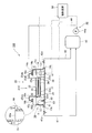
- the pickling apparatus 100 includes a pickling tank 10, a circulation tank (acid solution storage tank) 43, an acid solution circulation device (acid solution circulation means) 40, and And a control device (liquid level height adjusting means) 50.
- the pickling tank 10 is a deep bottom tank.
- the pickling tank 10 includes a bottom plate 11, a front side plate 12, a rear side plate 13, a right side plate 14, and a left side plate 15. Cover member 25 (four in the illustrated example).
- the bottom plate 11 extends in the sheet passing direction (traveling direction) of the steel strip S, and is provided with a gradient so as to be the lowest point at a first discharge port 15b (central circulation port) described later in detail. .
- the front side plate 12, the rear side plate 13, the right side plate 14, and the left side plate 15 form a vertical wall of the pickling tank 10.
- a rubber lining is applied to an acid-resistant material such as a resin such as polypropylene or a composite material thereof, or a steel can body, and an acid-resistant brick is formed thereon. It is possible to use what was done.
- the front side plate 12 is connected to the front end portion of the bottom plate 11 that forms the upstream side of the strip steel plate S in the sheet passing direction.
- the rear side plate 13 is connected to the rear end portion of the bottom plate 11 that forms the downstream side of the strip steel plate S in the sheet passing direction.
- the right side plate 14 is connected to the end portion on the right side in the width direction of the bottom plate 11 over the whole in the sheet passing direction of the steel strip S.
- An upstream end and a downstream end of the right side plate 14 in the plate passing direction of the steel strip S are connected to the front plate 12 and the rear plate 13.
- the left side plate 15 is connected to the end portion on the left side in the width direction of the bottom plate 11 in the plate passing direction of the steel strip S.
- An upstream end and a downstream end of the left side plate 15 in the sheet passing direction of the strip S are connected to the front plate 12 and the rear plate 13.
- the left side plate 15 and the right side plate 14 are respectively provided with a first discharge port 15b and a second discharge port 14b on the lower side in the center in the sheet passing direction of the steel strip S.
- a front flange portion 12a is formed on the upper end portion side of the front plate 12 so as to extend horizontally to the upstream side in the sheet passing direction of the strip steel plate S.
- a rear flange portion 13 a that extends horizontally downstream in the sheet passing direction of the strip steel plate S is formed.
- the front flange portion 12a and the rear flange portion 13a are provided with an entrance-side skid 31 and an exit-side skid 32, respectively.
- a right flange portion 14a and a left flange portion 15a extending inward in the width direction of the pickling tank 10 are formed on the upper end side of the right side plate 14 and the left side plate 15, a right flange portion 14a and a left flange portion 15a extending inward in the width direction of the pickling tank 10 are formed.
- a right receiving portion 16a and a left receiving portion 16b are provided on the right flange portion 14a and the left flange portion 15a, respectively. Sealing liquid is respectively stored in the right receiving portion 16a and the left receiving portion 16b, and the end portions of the right side plate 25d and the left side plate 25e of the cover member 25 are immersed. Thereby, the upper part of the width direction both ends of the pickling tank 10 is sealed by the cover member 25.
- a plurality (three in the illustrated example) of width direction receiving portions 17 having a shape extending in the width direction of the pickling tank 10 are bridged.
- the plurality of width direction receiving portions 17 are arranged adjacent to each other in the sheet passing direction of the strip steel plate S.
- the width direction receiving part 17 is arrange
- the pickling tank 10 is provided with a plurality of heat exchangers (heating means) 18 (two in the illustrated example).
- the plurality of heat exchangers 18 are arranged adjacent to each other in the sheet passing direction of the steel strip S.
- the heat exchanger 18 is disposed in the vicinity of the right side plate 14 in the bottom plate 11 of the pickling tank 10 below the right flange portion 14a.
- the heat exchanger 18 has substantially the same height as the sheet passing height h of the steel strip S.
- each of the heat exchangers 18 is a heat transfer pipe arranged so as to spread in the height direction and the side plate width direction, and has a function of indirectly heating by supplying a heat medium (for example, steam) into the pipe. Have. Therefore, at least a part of the heat exchanger 18 is immersed in the acid solution L in the pickling tank 10, so that the acid solution L in the pickling tank 10 can be heated to a predetermined temperature.
- a heat medium for example, steam
- the pickling tank 10 has a guide device (strip steel plate guide device) 20 for guiding the steel strip S.
- the guide device 20 includes a plurality (four in the illustrated example) of guide device bodies 21A to 21D.
- the plurality of guide device main bodies 21A to 21D are arranged adjacent to each other in the sheet passing direction of the strip steel sheet S.
- Each of the guide device main bodies 21A to 21D includes a bowl-shaped member (immersion box) 22 having a U-shaped cross section, an immersion guide roll 23, a skid 24, and a support block 26.
- the bowl-shaped member 22 extends in the sheet passing direction of the strip steel sheet S, and has a shape that opens on the upstream side and the downstream side of the strip sheet S in the sheet passing direction.
- the bowl-shaped member 22 has a bottom plate portion 22a, a right plate portion 22c, and a left plate portion 22d.
- the right side plate portion 22c and the left side plate portion 22d face each other.
- One end portion (one end portion in the width direction of the strip steel plate S) and the other end portion (the other end portion in the width direction of the strip steel plate S) in the bottom plate portion 22a are in the sheet passing direction of the strip steel plate S. It connects with the right side board part 22c and the left side board part 22d over the whole.
- the bowl-shaped member 22 is supported by a support block 26.
- the skid 24 is provided on the front end portion side of the bottom plate portion 22a, which forms an end portion on the upstream side in the sheet passing direction of the strip steel plate S.
- the skid 24 is also provided on the rear end side of the bottom plate portion 22a that forms the end on the downstream side in the sheet passing direction of the strip steel plate S. It is done.
- the immersion guide roll 23 is provided on the front end portion side of the cover member main body 25a, which will be described later in detail, forming an end portion on the upstream side in the sheet passing direction of the strip steel plate S.
- the support block 26 is provided below the skid 24 on the front end side of the bottom plate portion 22a, which forms an end portion on the upstream side of the strip steel plate S in the sheet passing direction.
- the support blocks 26 are provided at both ends in the width direction of the strip steel plate S, respectively.
- the cover member 25 includes a cover member main body 25a, a front side plate 25b, a rear side plate 25c, a right side plate 25d, and a left side plate 25e.
- the cover member body 25a has a plate shape.
- the cover member main body 25a is disposed above the bowl-shaped member 22.
- the front side plate 25b is connected to the front end portion of the cover member main body 25a and has a shape extending upward. On the upper end side of the front side plate 25b, a front flange portion 25ba extending to the upstream side in the sheet passing direction of the strip steel plate S is formed. In the cover member 25 arranged corresponding to the second to fourth guide device main bodies 21B to 21D, the front end portion of the front flange portion 25ba of the front side plate 25b is bent downward to form the width direction receiving portion 17. It is immersed in the sealing liquid stored in the.
- the rear side plate 25c is connected to the rear end portion of the cover member main body 25a and has a shape extending upward.
- a rear flange portion 25ca extending to the downstream side in the sheet passing direction of the strip steel plate S is formed on the upper end portion side of the rear plate 25c.
- the front end portion of the rear flange portion 25ba of the rear side plate 25c is bent downward to form the width direction receiving portion 17. It is immersed in the sealing liquid stored in the.
- the right side plate 25d is connected to the right end of the cover member body 25a and has a shape extending upward.
- a right flange portion 25da extending outward in the width direction of the strip S is formed.
- the front end portion of the right flange portion 25da is bent downward and is immersed in the sealing liquid stored in the right receiving portion 16a.
- the left side plate 25e is connected to the left end portion of the cover member body 25a and has a shape extending upward.
- a left flange portion 25ea extending outward in the width direction of the strip steel plate S is formed on the upper end portion side of the left side plate 25e.
- the front end portion of the left flange portion 25ea is bent downward and is immersed in the sealing liquid stored in the left receiving portion 16b.
- the upper part of the pickling tank 10 is covered by the cover member 25 provided corresponding to the first to fourth guide device bodies 21A to 21D.
- the acid solution circulation device 40 includes a first discharge pipe (acid solution flow path) 41, a second discharge pipe 42, and a supply pipe (return pipe) 44.
- the first discharge pipe 41 has a base end side (one end side) connected to the first discharge port 15 b of the pickling tank 10 and a tip end side (the other end side) connected to the circulation tank 43. ing.
- the first discharge pipe 41 is provided with an on-off valve 41a.
- the second discharge pipe 42 has a proximal end side connected to the second discharge port 14 b of the pickling tank 10 and a distal end side (the other end side) connected to the circulation tank 43.
- the second discharge pipe 42 is provided with an on-off valve 42a.
- the supply pipe 44 has a base end side (one end side) connected to the circulation tank 43 and a tip end side (the other end side) connected to the supply port 14 c of the pickling tank 10.
- the supply pipe 44 is provided with a circulation pump 44a.
- the circulation tank 43 is preferably provided below the pickling tank 10. This is because the acid solution L can be extracted from the pickling tank 10 to the circulation tank 43 without a pump.
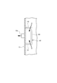
- the pickling apparatus 100 further includes a weir 60 provided in the pickling tank 10, as shown in FIGS.
- the discharge port 15b is at the center and the lower end of the left side plate 15 in the width direction.
- the weir 60 has a shape surrounding the first discharge port 15 b and includes a front side plate portion 61, a rear side plate portion 62, and a lateral side plate portion 63.
- the front side plate portion 61 of the weir 60 is connected to the left side plate 15 and the bottom plate 11 and extends in the width direction of the pickling tank 10.
- the rear side plate portion 62 of the weir 60 is connected to the left side plate 15 and the bottom plate 11.
- the rear side plate portion 62 of the weir 60 is separated from the front side plate portion 61 and has a shape extending in parallel with the front side plate portion 61.
- the lateral side plate portion 63 of the weir 60 is connected to the end portion of the front side plate portion 61, the end portion of the rear side plate portion 62 and the bottom plate 11, and has a shape extending in the plate passing direction of the band steel plate S.
- the upper end (inlet) 60a of the weir 60 is lower than the sheet-plate height h of the steel strip S in the pickling tank 10 and is one third of the liquid level La of the acid solution L during the pickling operation.
- the weir 60 forms an inflow path connected to the first discharge port 15b, the acid solution L overflows from the upper end 60a, and the acid surface Lb of the acid solution L is greater than the plate height h of the steel strip S. It constitutes a part of the liquid level adjusting means that adjusts and holds downward.
- the inlet channel may be provided outside the pickling tank 10 by connecting an inlet to the left side plate 15 of the pickling tank 10.
- the weir 60 is preferably made of the same material as the pickling tank 10.
- the pickling tank 10 is made of resin
- the weir 60 is also preferably made of the same resin as the pickling tank 10. This is because the acid solution L in the pickling tank 10 is held at a high temperature (for example, 85 to 90 ° C.) during the pickling operation and during the pickling pause, and the weir 60 also heats with the pickling tank 10. Because it can. This is because if the pickling tank 10 and the weir 60 are made of different materials, the possibility of causing breakage due to the difference in the thermal elongation at the connecting portion between the pickling tank 10 and the weir 60 is increased.
- the control device 50 is a device that controls each device of the pickling apparatus 100.
- the output side of the control device 50 is connected to the heat exchanger 18, the on-off valves 41a and 42a, and the circulation pump 44a, so that the operation of these devices can be controlled.
- the controller 50 controls the heat exchanger 18 to heat the acid solution L to a predetermined temperature (for example, 85 to 90 ° C.) so that the acid solution L does not circulate.
- the acid solution circulation device 40 is controlled. That is, the control device 50 controls the on-off valves 41a, 42a so that the on-off valves 41a, 42a provided in the first and second discharge pipes 41, 42 are fully closed, and the circulation pump 44a stops.
- the acid solution L is heated to the predetermined temperature, and the liquid level La of the acid solution L is held at substantially the same height as the cover member main body 25a of the cover member 25. . Therefore, the steel strip S is pickled by traveling in the acid solution L while being immersed in the acid solution L while being guided by the immersion guide roll 23 and the skid 24.
- the control device 50 adds the acid solution L to a predetermined temperature (for example, 85 to 90 ° C.) during the pickling pause.
- the heat exchanger 18 is controlled to warm, and the acid solution circulation device 40 is controlled so that the acid solution L circulates. That is, the control device 50 controls the open / close valve 42a so that the open / close valve 42a provided in the second discharge pipe 42 is fully closed, and the open / close valve 41a provided in the first discharge pipe 41 is fully open.
- the on-off valve 41a is controlled so that As a result, the acid solution L in the pickling tank 10 gets over the upper end 60a of the weir 60 and flows downward in the weir 60 to reach the vicinity of the first discharge port 15b, and from the first discharge port 15b to the second position. It flows into the circulation tank 43 through the one discharge pipe 41 and is temporarily stored in the circulation tank 43. The acid solution L in the pickling tank 10 is discharged into the circulation tank 43 through the first discharge pipe 41, and the liquid level Lb of the acid solution L in the pickling tank 10 is substantially the same as the upper end portion 60a of the weir 60. Become height. Thereafter, the control device 50 controls the opening degree of the on-off valve 41a and controls the circulation pump 44a to operate.
- the acid solution L temporarily stored in the circulation tank 43 flows into the pickling tank 10 through the supply pipe 44 by the operation of the circulation pump 44a. That is, the first discharge pipe 41 and the supply pipe 44 form two flow paths through which the acid liquid L flows between the pickling tank 10 and the circulation tank 43.
- the state in which the acid solution L is substantially the same height as the upper end portion 60a of the weir 60 is determined based on the signal provided with a liquid level sensor. It is conceivable that the elapsed time reached is checked and a determination is made based on the elapsed time.
- the flow rate (supply amount) of the acid solution supplied to the pickling tank 10 by the circulation pump 44a is designed or adjusted so as not to exceed the flow rate (discharge amount) that can flow out of the pickling tank 10 over the weir 60,
- the level of the acid solution L is maintained at the height of the upper end portion 60a.
- the acid solution L is circulated between the pickling tank 10 and the circulation tank 43 by the acid solution circulation device 40, and the circulating acid solution L is brought to the predetermined temperature by the heat exchanger 18 in the pickling tank 10. It will be heated.
- the pickling height of the strip steel plate S is changed to the level Lb of the acid solution L in the pickling tank 10 during the pickling pause in which the pickling of the strip steel plate S is temporarily stopped.
- the acid solution L is circulated between the pickling tank 10 and the circulation tank 43 in a state of being held below h, and the pickling of the steel strip S at this time can be prevented.
- the acid liquid L is heated to a predetermined temperature by the heat exchanger 18 and the acid liquid L is circulated between the pickling tank 10 and the circulation tank 43 by the acid liquid circulation device 40, the total amount of acid Compared with the case where the liquid is discharged from the pickling tank and stored in a tank separate from the pickling tank, the amount of the acid liquid L returned to the pickling tank 10 is small and stored in another tank. Therefore, the temperature drop of the acid solution can be prevented, and the switching time between the pickling operation and the pickling pause can be shortened.
- the control device 50 controls the opening and closing of the on-off valve 41a and the operation of the circulation pump 44a, thereby reliably preventing over-acid washing of the steel strip S during the pickling pause while having a simple configuration. In addition, the switching time between the pickling operation and the pickling pause can be shortened.
- the height of the weir 60 is such that a part of the heat exchanger 18 is immersed in the acid solution L so that heating necessary for maintaining the acid solution temperature is possible during the pickling pause.
- the liquid level of the acid solution L is adjusted. Thereby, the acid solution L in the pickling tank 10 can be reliably heated by the heat exchanger 18.
- the pickling tank 10 has a depth at which the upper end of the heat exchanger 18 is disposed in the acid solution L at the same height as the sheet passing height h of the steel strip S.
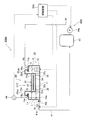
- FIGS. 4 and 5 A pickling apparatus according to a second embodiment of the present invention will be described with reference to FIGS. 4 and 5.
- This embodiment has a configuration in which the acid solution circulation device and the control device included in the first embodiment shown in FIGS.
- Other configurations are substantially the same as those of the apparatus shown in FIGS. 1 and 2 and described above, and the same components are denoted by the same reference numerals and redundant description is omitted as appropriate.
- the pickling apparatus 100A includes the same equipment as the acid apparatus 100 according to the first embodiment described above, and an acid solution circulation device (acid solution circulation means). 40A, a liquid level sensor (liquid level height measuring means) 64, and a control device (liquid level height adjusting means) 50A. That is, the pickling apparatus 100A includes a liquid level sensor 64 instead of the weir included in the pickling apparatus 100.
- the acid solution circulation device 40A includes a first discharge pipe 41, an on-off valve 41a, a supply pipe 44, and a circulation pump 44a.
- the acid liquid L in the pickling tank 10 is the 1st discharge pipe 41, a circulation tank 43, and fed into the pickling tank 10 through the supply pipe 44, and the level Lb of the acid solution L is lower than the plate height h of the steel strip S in the pickling tank 10. It is held at a predetermined height.
- the liquid level sensor 64 is a device that detects the height of the acid level of the acid solution L in the pickling tank 10.
- the tip end portion 64 a of the liquid level sensor 64 is positioned below the bowl-shaped member 22 of the guide device 20.
- the output side of the liquid level sensor 64 is connected to the control device 50A.
- the liquid level sensor 64 detects the level of the acid liquid L in the pickling tank 10
- the liquid level of the acid liquid L is detected.
- the height information is transmitted to the control device 50A.
- the input side of the control device 50A is connected to the liquid level sensor 64.
- the output side of the control device 50A is connected to the heat exchanger 18, the on-off valve 41a, and the circulation pump 44a.
- the control device 50A heats the acid solution L to a predetermined temperature (for example, 85 to 90 ° C.). 18 is controlled to control the acid solution circulation device 40A so that the acid solution L does not circulate. That is, the control device 50A controls the on-off valve 41a so that the on-off valve 41a provided in the first discharge pipe 41 is fully closed, and controls the circulation pump 44a to stop.
- the acid solution L is heated to the predetermined temperature, and the liquid level La of the acid solution L is held at substantially the same height as the cover member main body 25a of the cover member 25. . Therefore, the steel strip S is pickled by traveling in the acid solution L while being immersed in the acid solution L while being guided by the immersion guide roll 23 and the skid 24.
- the control device 50A While pickling operation is temporarily stopped (for example, several hours to one day), the control device 50A adds the acid solution L to a predetermined temperature (for example, 85 to 90 ° C.).
- the heat exchanger 18 is controlled to warm, and the acid solution circulation device 40A is controlled so that the acid solution L circulates. That is, the control device 50A controls the on-off valve 41a so that the on-off valve 41a provided in the first discharge pipe 41 is fully opened.
- the acid solution L in the pickling tank 10 flows from the first discharge port 15 b to the circulation tank 43 through the first discharge pipe 41 and is temporarily stored in the circulation tank 43. Will be.
- control device 50A controls the opening degree of the on-off valve 41a when the liquid level Lb of the acid solution L in the pickling tank 10 detected by the liquid level sensor 64 falls below the guide device bodies 21A to 21D.
- the circulation pump 44a is controlled to operate. As a result, the acid solution L temporarily stored in the circulation tank 43 flows into the pickling tank 10 through the supply pipe 44 by the operation of the circulation pump 44a.
- the liquid level Lb of the acid solution L in the pickling tank 10 is lowered below the sheet plate height h in the pickling tank 10 to this state. Then, the acid solution L is circulated between the pickling tank 10 and the circulation tank 43 by the acid solution circulation device 40A, and the circulating acid solution L is heated to the predetermined temperature by the heat exchanger 18 in the pickling tank 10. Will be.
- the acid liquid L circulates between the pickling tank 10 and the circulation tank 43 in a state where Lb is held below the plate height h of the steel sheet S, and the peracid of the steel sheet S at this time is circulated. Washing can be prevented.
- the acid liquid L is heated to a predetermined temperature by the heat exchanger 18 and the acid liquid L is circulated between the pickling tank 10 and the circulation tank 43 by the acid liquid circulation device 40A, the total amount of the acid liquid Compared to the case where the acid is discharged from the pickling tank and stored in a tank separate from the pickling tank, the amount of the acid solution L returned to the pickling tank 10 is small and stored in another tank. Therefore, it is possible to shorten the time for switching between pickling operation and pickling pause.
- the control device 50A controls the opening / closing of the on-off valve 41a and the operation of the circulation pump 44a, thereby reliably preventing over-acid washing of the steel strip S during the pickling pause while having a simple configuration. In addition, the switching time between the pickling operation and the pickling pause can be shortened.
- the control device 50A controls the opening / closing of the on-off valve 41a and the operation of the pump 44a based on the liquid level height of the acid liquid L measured by the liquid level sensor 64, while having a simple configuration. In addition, it is possible to more reliably prevent the perforation of the steel strip S during the pickling pause, and to shorten the switching time between the pickling operation and the pickling pause.
- the pickling apparatus 100 provided with the weir 60 surrounding the first discharge port 15b as the inflow path of the liquid level height adjusting means has been described. It is also possible to provide a pickling apparatus that includes an overflow pipe that is connected to the discharge port and has an inlet positioned below the plate height of the steel strip as an inflow path of the liquid level height adjusting means. Even in such a pickling apparatus, the acid solution overflows from the overflow pipe, and the acid solution level can be maintained below the sheet plate height of the strip steel plate.
- the pickling apparatuses 100 and 100A provided with the guide apparatus 20 provided with a plurality of guide apparatus main bodies having the bowl-shaped member 22 provided with the immersion guide roll 23 and the skid 24 in the sheet passing direction of the strip steel sheet S are used.
- the pickling apparatus provided with the support roll etc. which support the lower surface side of the said strip steel plate so that a strip steel plate can be passed.
- the pickling apparatuses 100 and 100A including the guide apparatus 20 including the four guide apparatus bodies 21A to 21D have been described.
- the pickling apparatuses 100 and 100A are immersed in the acid solution and run in the sheet passing direction of the strip. If the band steel plate can be supported as much as possible, the number of guide device main bodies is not limited to four, and the pickling device should have three or less guide device main bodies or five or more guide device main bodies. Is also possible.
- the first discharge port 15b and the second discharge port 14b of the pickling tank 10 are connected to the first discharge pipe 41 and the second discharge pipe 42, and the supply port 14c and the supply pipe 44 of the pickling tank 10 are connected.
- the pickling apparatus 100,100A provided with the two heat exchangers 18 arrange
- the number of exchangers is not limited to two, and a pickling apparatus including one heat exchanger or three or more heat exchangers may be used. It is also possible to provide a pickling apparatus including heat exchangers disposed only in the vicinity of the left side plate 15 of the pickling tank 10, or in the vicinity of the right side plate 14 and in the vicinity of the left side plate 15 of the pickling tank 10.
- the pickling apparatuses 100 and 100A including the cover members 25 provided corresponding to the respective guide apparatus main bodies 21A to 21D have been described, but the upper portion of the pickling tank 10 is covered with one cover member. It is also possible to use a pickling apparatus.
- the pickling apparatus 100, 100A using a water seal is used as the sealing method for the end portion of the cover member 25.
- a rubber having a rubber seal attached to the end portion of the cover member is also possible to use a pickling apparatus using packing.
- the pickling apparatus including the pickling tank and the circulation tank disposed below the pickling tank has been described.
- the arrangement of the pickling tank and the circulation tank is not limited thereto. It is sufficient that the acid solution can be circulated between the pickling tank and the circulation tank by the acid solution circulation device.
- the pickling apparatus has a circulation tank arranged above the pickling tank, or the pickling tank and the circulation tank are at the same height. It is also possible to use a pickling device arranged in the above.
- the acid-liquid circulation apparatus 40 and 40A which has the on-off valve 41a provided in the 1st discharge pipe 41, and the circulation pump 44a provided in the supply pipe 44, a pickling tank and an acid It is only necessary to be able to circulate the acid solution between the liquid circulation tank and the acid solution circulation device having the pump provided in both the discharge pipe and the supply pipe, or the pump provided in both the discharge pipe and the supply pipe It is also possible to provide an acid solution circulation device having an on-off valve or an acid solution circulation device having a pump provided on the discharge pipe and an on-off valve provided on the supply pipe.
Landscapes
- Chemical & Material Sciences (AREA)
- Chemical Kinetics & Catalysis (AREA)
- General Chemical & Material Sciences (AREA)
- Engineering & Computer Science (AREA)
- Materials Engineering (AREA)
- Mechanical Engineering (AREA)
- Metallurgy (AREA)
- Organic Chemistry (AREA)
- Cleaning And De-Greasing Of Metallic Materials By Chemical Methods (AREA)
Abstract
酸洗一時停止中における帯鋼板の過酸洗を防止し、酸洗運転と酸洗一時停止との切り替え時間を短くすることができるようにするために、酸液(L)が溜められ、帯鋼板(S)を酸液に浸漬した状態で通板させることで当該帯鋼板を酸洗する酸洗槽(10)と、酸洗槽内の酸液を加温する熱交換器(18)と、酸洗槽とは別に設けられ、酸液を貯留する循環槽(43)と、酸洗槽と循環槽との間で酸液を循環する酸液循環装置(40)と、酸液循環装置(40)を制御して酸洗槽内の酸液の液面を帯鋼板の通板高さ(h)より下方に保持する制御装置(50)とを設ける。
Description
本発明は、酸洗装置およびその酸洗一時停止時運転方法に関する。
酸洗装置は、冷延鋼板や熱延鋼板といった帯鋼板の表面に形成された酸化物である酸化スケールを、塩酸や硫酸などの酸液と反応させることによって洗浄除去する装置である。一般的な酸洗装置では、酸洗槽内へ帯鋼板を連続的に通板し、帯鋼板に酸液を噴射したり、帯鋼板を酸洗槽に貯留した酸液に浸漬したりすることで、帯鋼板表面の酸化スケールを連続的に除去している。
下記特許文献1には、鋼帯の走行方向へ横長であり、長手方向中央部で浅く、入り側および出側の両端部で深い形状である酸液受容槽およびこれを覆う槽蓋で構成される酸洗槽と、酸液受容槽中央部の両端の槽底に設けられた堰と、堰間に設けられた複数のサポートロールと、サポートロールに支持される鋼帯に酸液を噴射する酸液供給ヘッダと、酸液供給ヘッダと酸液供給ラインを介して接続されると共に、酸液受容槽と戻りラインを介して接続される循環槽と、酸液供給ラインに設けられた熱交換器とを備え、酸液供給ヘッダが酸液を鋼帯に噴射することにより連続的に酸洗を行う酸洗装置が記載されている。
下記特許文献2には、酸液を満たした酸洗槽と、酸洗槽の上部を覆う蓋と、蓋の下面に回転自在に設けられた浸漬ガイドロールと、酸洗槽の底面に設けられた支持ブロックと、支持ブロックの上部に設けられた底板と、底板の上面に浸漬ガイドロールと対向して設けられたスキッドとを備え、浸漬ガイドロールおよびスキッドで帯鋼板をガイドしながら酸液中を走行させることで当該帯鋼板を酸洗処理する酸洗装置が記載されている。
ところで、酸洗装置を備える設備において、帯鋼板の走行方向で上流側や下流側に配置される装置の保守などで当該帯鋼板の走行を一時的に(例えば、数時間から1日程度)停止する場合がある。このとき、帯鋼板が酸洗槽の酸液に浸漬した状態で当該帯鋼板の走行を停止すると、帯鋼板の酸洗が進行して過酸洗となることから、酸洗槽と別に設けられる循環槽へ酸洗槽内の酸液を移送したり、帯鋼板を酸液の上方に持ち上げたりするなどの処理が行われていた。
特許文献1に記載の酸洗装置では、酸洗一時停止時に酸洗槽内の酸液を循環槽へ移送することで鋼帯の過酸洗を防ぎ、酸洗運転時には熱交換器により酸液を加熱することができるものの、酸洗停止時間に応じて酸液の温度が低下し、酸洗一時停止から酸洗運転への切り替えに多大な時間を要していた。
特許文献2に記載の酸洗装置では、酸洗一時停止時に帯鋼板の過酸洗を防ぐためには、帯鋼板と共に、浸漬ガイドロールおよびスキッドなどもリフト装置で持ち上げる必要があることから、リフト装置が大型で強度のある装置となり、装置コストが高くなってしまう可能性があった。また、酸洗槽と別に設けた循環槽に酸洗槽内の酸液を移送することも考えられるが、酸液が多く、酸洗停止時間に応じて酸液の温度が低下することから、酸洗一時停止から酸洗運転への切り替えに多大な時間を要する可能性があった。
以上のことから、本発明は、前述した課題を解決するために為されたもので、酸洗一時停止中における帯鋼板の過酸洗を防止し、酸洗運転と酸洗一時停止との切り替え時間を短くすることができる酸洗装置およびその酸洗一時停止時運転方法を提供することを目的としている。
上述した課題を解決する本発明に係る酸洗装置は、
酸液が溜められ、帯鋼板を前記酸液に浸漬した状態で通板させることで当該帯鋼板を酸洗する酸洗槽と、
前記酸洗槽内の記酸液を加温する加温手段と、
前記酸洗槽とは別に設けられ、前記酸液を貯留する酸液貯留槽と、
前記酸洗槽と前記酸液貯留槽との間で前記酸液を循環する酸液循環手段と、
前記酸液循環手段を制御して前記酸洗槽内の前記酸液の液面を前記帯鋼板の通板高さより下方に保持する液面高さ調整手段と
を有する
ことを特徴とする。
酸液が溜められ、帯鋼板を前記酸液に浸漬した状態で通板させることで当該帯鋼板を酸洗する酸洗槽と、
前記酸洗槽内の記酸液を加温する加温手段と、
前記酸洗槽とは別に設けられ、前記酸液を貯留する酸液貯留槽と、
前記酸洗槽と前記酸液貯留槽との間で前記酸液を循環する酸液循環手段と、
前記酸液循環手段を制御して前記酸洗槽内の前記酸液の液面を前記帯鋼板の通板高さより下方に保持する液面高さ調整手段と
を有する
ことを特徴とする。
上述した課題を解決する本発明に係る酸洗装置の酸洗一時停止時運転方法は、
帯鋼板を酸液に浸漬した状態で通板させることで当該帯鋼板を酸洗する酸洗槽と、前記酸洗槽内の前記酸液を加温する加温手段と、前記酸液を貯留する酸液貯留槽と前記酸洗槽との間で前記酸液を循環する循環手段とを有する酸洗装置の酸洗一時停止時運転方法であって、
前記帯鋼板の酸洗一時停止時に、前記酸洗槽内の前記酸液の液面を前記帯鋼板の通板高さより下方に保持しつつ、前記酸液貯留槽と前記酸洗槽との間で前記酸液を前記酸液循環手段により循環し、循環する前記酸液を前記酸洗槽内で前記加温手段により加温する
ことを特徴とする。
帯鋼板を酸液に浸漬した状態で通板させることで当該帯鋼板を酸洗する酸洗槽と、前記酸洗槽内の前記酸液を加温する加温手段と、前記酸液を貯留する酸液貯留槽と前記酸洗槽との間で前記酸液を循環する循環手段とを有する酸洗装置の酸洗一時停止時運転方法であって、
前記帯鋼板の酸洗一時停止時に、前記酸洗槽内の前記酸液の液面を前記帯鋼板の通板高さより下方に保持しつつ、前記酸液貯留槽と前記酸洗槽との間で前記酸液を前記酸液循環手段により循環し、循環する前記酸液を前記酸洗槽内で前記加温手段により加温する
ことを特徴とする。
本発明によれば、帯鋼板の酸洗を一時停止しているときに、酸洗槽内の酸液の液面を帯鋼板の通板高さより下方に保持した状態で、酸洗槽と酸液貯留槽との間で酸液が循環することになり、このときの帯鋼板の過酸洗を防止することができる。また、加温手段により酸液を所定温度に加温し、酸液循環手段により酸液が酸洗槽と酸液貯留槽との間で循環していることから、全量の酸液を酸洗槽内から排出して酸洗槽とは別のタンクに貯留しておく場合と比べて、酸洗運転と酸洗一時停止との切り替え時間を短くすることができる。
本発明に係る酸洗装置およびその酸洗一時停止時運転方法を実施するための形態について以下に説明するが、本発明は、図面に基づいて説明する以下の実施形態のみに限定されるものではない。
[第一の実施形態]
本発明の第一の実施形態に係る酸洗装置について、図1、図2および図3を参照して説明する。
本発明の第一の実施形態に係る酸洗装置について、図1、図2および図3を参照して説明する。
本実施形態に係る酸洗装置100は、図1および図2に示すように、酸洗槽10と、循環槽(酸液貯留槽)43と、酸液循環装置(酸液循環手段)40と、制御装置(液面高さ調整手段)50とを備える。
酸洗槽10は、深底の槽である。酸洗槽10は、底板11と前側板12と後側板13と右側板14と左側板15とを備え、上方が開口し、酸液Lが溜められる容器本体と、容器本体の開口を覆う複数(図示例では4つ)のカバー部材25とを有する。底板11は、帯鋼板Sの通板方向(走行方向)で延在し、詳細につき後述する第一の排出口15b(中央部循環口)にて最下点となるよう勾配が設けられている。前側板12、後側板13、右側板14および左側板15は、酸洗槽10の縦壁をなしている。なお、酸洗槽10およびカバー部材25などとして、ポリプロピレン等の樹脂又はその複合材料のような耐酸性の材料で作製されたものや鋼缶体にゴムライニングを施し、その上から耐酸レンガによって作製されたものを用いることが可能である。
前側板12は、帯鋼板Sの通板方向上流側をなす底板11の前端部と接続している。後側板13は、帯鋼板Sの通板方向下流側をなす底板11の後端部と接続している。右側板14は、帯鋼板Sの通板方向にて全体に亘り底板11の幅方向右側の端部と接続している。右側板14における帯鋼板Sの通板方向の上流側端部および下流側端部は、前側板12および後側板13と接続している。左側板15は、帯鋼板Sの通板方向にて全体に亘り底板11の幅方向左側の端部と接続している。左側板15における帯鋼板Sの通板方向の上流側端部および下流側端部は、前側板12および後側板13と接続している。
左側板15および右側板14には、帯鋼板Sの通板方向中央の下方側にて第一の排出口15bおよび第二の排出口14bがそれぞれ設けられている。
前側板12の上端部側には、帯鋼板Sの通板方向上流側へ水平に延在する前フランジ部12aが形成されている。後側板13の上端部側には、帯鋼板Sの通板方向下流側へ水平に延在する後フランジ部13aが形成されている。前フランジ部12aおよび後フランジ部13aには、入側のスキッド31および出側のスキッド32がそれぞれ設けられている。
右側板14および左側板15の上端部側には、酸洗槽10の幅方向内側へ延在する右フランジ部14aおよび左フランジ部15aがそれぞれ形成されている。右フランジ部14aおよび左フランジ部15aには、右受け部16aおよび左受け部16bがそれぞれ設けられている。右受け部16aおよび左受け部16bには、シール液がそれぞれ溜められており、カバー部材25の右側板25dおよび左側板25eの端部が浸漬するようになっている。これにより、酸洗槽10の幅方向両端部の上方は、カバー部材25でシールされることになる。
右側板14と左側板15との間には、酸洗槽10の幅方向で延在する形状をなす幅方向受け部17が複数(図示例では3つ)架け渡されている。複数の幅方向受け部17は、帯鋼板Sの通板方向にて隣接して配置される。
幅方向受け部17は、帯鋼板Sの通板方向で隣接する案内装置本体(後述)の間に配置される。幅方向受け部17には、シール液が溜められており、カバー部材25の前側板25bおよび後側板25cの端部が浸漬するようになっている。これにより、酸洗槽10における帯鋼板Sの通板方向にて隣接する案内装置本体間の上方は、カバー部材25でシールされることになる。
酸洗槽10には、熱交換器(加温手段)18が複数(図示例では2つ)設けられている。複数の熱交換器18は、帯鋼板Sの通板方向にて隣接して配置される。熱交換器18は、右フランジ部14aの下方で、酸洗槽10の底板11における右側板14近傍に配置される。熱交換器18は、帯鋼板Sの通板高さhとほぼ同じ高さを有する。また、熱交換器18は、それぞれが、高さ方向及び側板幅方向に広がって配置された伝熱管であって、管中に熱媒(例えば蒸気)を供給することにより間接加温する機能を有する。よって、熱交換器18の少なくとも一部が酸洗槽10内の酸液Lに浸漬されることにより、酸洗槽10内の酸液Lを所定温度に加温することが可能となる。
酸洗槽10は、帯鋼板Sを案内する案内装置(帯鋼板案内装置)20を有する。案内装置20は、複数(図示例では4つ)の案内装置本体21A~21Dを有する。複数の案内装置本体21A~21Dは、帯鋼板Sの通板方向にて隣接して配置される。案内装置本体21A~21Dは、横断面形状がU字状をなす樋状部材(浸漬ボックス)22と、浸漬ガイドロール23と、スキッド24と、支持ブロック26とをそれぞれ有する。
樋状部材22は、帯鋼板Sの通板方向へ延在し、当該帯鋼板Sの通板方向上流側およびその下流側で開口する形状をなしている。樋状部材22は、底板部22aと右側板部22cと左側板部22dとを有する。右側板部22cと左側板部22dとが対向している。底板部22aにおける一方の端部(帯鋼板Sの幅方向にて一方の端部)および他方の端部(帯鋼板Sの幅方向にて他方の端部)は、帯鋼板Sの通板方向全体に亘り右側板部22cおよび左側板部22dと接続している。樋状部材22は、支持ブロック26により支持されている。
スキッド24は、帯鋼板Sの通板方向上流側の端部をなす、底板部22aの前端部側に設けられる。帯鋼板Sの通板方向下流側の第四の案内装置本体21Dにおいては、スキッド24は、帯鋼板Sの通板方向下流側の端部をなす、底板部22aの後端部側にも設けられる。浸漬ガイドロール23は、帯鋼板Sの通板方向上流側の端部をなす、詳細につき後述するカバー部材本体25aの前端部側に設けられる。
支持ブロック26は、帯鋼板Sの通板方向上流側の端部をなす、底板部22aの前端部側でスキッド24の下方に設けられる。支持ブロック26は、帯鋼板Sの幅方向両端部にそれぞれ設けられる。これにより、案内装置本体21A~21Dが酸洗槽10内にて所定の高さに配置されることになる。よって、帯鋼板Sの酸洗運転時に、酸洗槽10は、案内装置本体21A~21Dとほぼ同じ高さまで酸液Lで満たされ、帯鋼板Sは、酸液Lに浸漬した状態(所定の通板高さh)で案内されることになる。
カバー部材25は、カバー部材本体25aと、前側板25bと、後側板25cと、右側板25dと、左側板25eとを有する。カバー部材本体25aは、板状をなしている。カバー部材本体25aは、樋状部材22の上方に配置されている。
前側板25bは、カバー部材本体25aの前端部と接続し、上方へ延在する形状をなしている。前側板25bの上端部側には、帯鋼板Sの通板方向上流側へ延在する前フランジ部25baが形成されている。第二~第四の案内装置本体21B~21Dに対応して配置されるカバー部材25にあっては、前側板25bの前フランジ部25baの先端部が下方へ折り曲げられて、幅方向受け部17に溜められるシール液内に浸漬されている。
後側板25cは、カバー部材本体25aの後端部と接続し、上方へ延在する形状をなしている。後側板25cの上端部側には、帯鋼板Sの通板方向下流側へ延在する後フランジ部25caが形成されている。第一~第三の案内装置本体21A~21Cに対応して配置されるカバー部材25にあっては、後側板25cの後フランジ部25baの先端部が下方へ折り曲げられて、幅方向受け部17に溜められるシール液内に浸漬されている。
右側板25dは、カバー部材本体25aの右端部と接続し、上方へ延在する形状をなしている。右側板25dの上端部側には、帯鋼板Sの幅方向外側へ延在する右フランジ部25daが形成されている。右フランジ部25daの先端部が下方へ折り曲げられて、右受け部16aに溜められるシール液内に浸漬されている。
左側板25eは、カバー部材本体25aの左端部と接続し、上方へ延在する形状をなしている。左側板25eの上端部側には、帯鋼板Sの幅方向外側へ延在する左フランジ部25eaが形成されている。左フランジ部25eaの先端部が下方へ折り曲げられて、左受け部16bに溜められるシール液内に浸漬されている。
よって、第一~第四の案内装置本体21A~21Dに対応して設けられるカバー部材25により、酸洗槽10の上方が覆われることになる。
酸液循環装置40は、第一の排出管(酸液の流通路)41と、第二の排出管42と、供給管(戻り管)44とを備える。第一の排出管41は、基端側(一方の端部側)が酸洗槽10の第一の排出口15bと接続し、先端側(他方の端部側)が循環槽43と接続している。第一の排出管41には、開閉弁41aが設けられる。第二の排出管42は、基端側が酸洗槽10の第二の排出口14bと接続し、先端側(他方の端部側)が循環槽43と接続している。第二の排出管42には、開閉弁42aが設けられる。供給管44は、基端側(一方の端部側)が循環槽43と接続し、先端側(他方の端部側)が酸洗槽10の供給口14cと接続している。供給管44には循環ポンプ44aが設けられる。なお、循環槽43は、酸洗槽10より下方に設けられることが好ましい。酸洗槽10から酸液Lを循環槽43にポンプなしで抜き出せるからである。
酸洗装置100は、図1~図3に示すように、さらに、酸洗槽10内に設けられた堰60を有する。排出口15bは、左側板15の幅方向中央かつ下端にある。堰60は、第一の排出口15bを囲う形状をなしており、前側板部61と、後側板部62と、横側板部63とを有する。堰60の前側板部61は、左側板15および底板11と接続し酸洗槽10の幅方向へ延在する形状をなしている。堰60の後側板部62は、左側板15および底板11と接続している。堰60の後側板部62は、前側板部61と離間し、当該前側板部61と平行に延在する形状をなしている。堰60の横側板部63は、前側板部61の端部、後側板部62の端部および底板11と接続し、帯鋼板Sの通板方向で延在する形状をなしている。堰60の上端部(入口)60aは、酸洗槽10内での帯鋼板Sの通板高さhより下方、且つ酸洗運転中の酸液Lの液面Laに対して3分の1の高さより上方の範囲内であることが好ましく、樋状部材22の底板部22aより下方、且つ酸洗運転中の酸液Lの液面Laに対してその半分の高さより上方の範囲内であることがより好ましい。これは、酸洗一時停止中に、酸洗槽10内からの酸液Lの排出量を抑制しつつ、熱交換器18による酸液Lの加温を効率良く行うことができるからである。また、酸洗運転と酸洗一時停止との切り替えを短時間で行うことができるからである。すなわち、堰60は、第一の排出口15bと接続する流入路をなし、酸液Lが上端部60aより溢流して、酸液Lの液面Lbを帯鋼板Sの通板高さhより下方に調整して保持する液面調整手段の一部をなしている。なお、流入路は、酸洗槽10の左側板15に入口を接続し、酸洗槽10外に設けても良い。
なお、堰60は、酸洗槽10と同一の材質であることが好ましい。酸洗槽10が樹脂製である場合には堰60も酸洗槽10と同一の樹脂製であることが好ましい。これは、酸洗槽10内の酸液Lが酸洗運転中および酸洗一時停止中に高温(例えば、85~90℃)で保持されており、酸洗槽10とともに堰60も熱伸びすることができるからである。酸洗槽10と堰60が異材であると、酸洗槽10と堰60の接続箇所にてこれらの熱伸びの差に起因した破損を生じる可能性が高められてしまうからである。
制御装置50は、酸洗装置100の各機器を制御する装置である。制御装置50は、出力側が、熱交換器18、開閉弁41a,42aおよび循環ポンプ44aと接続しており、これら機器の動作を制御可能になっている。
ここで、上述した酸洗装置100の中心となる作動について以下に説明する。
酸洗運転中にあっては、制御装置50は、酸液Lを所定温度(例えば、85~90℃)に加温するように熱交換器18を制御し、酸液Lが循環しないように酸液循環装置40を制御する。すなわち、制御装置50は、第一および第二の排出管41,42に設けられる開閉弁41a,42aが全閉状態となるように当該開閉弁41a,42aを制御し、循環ポンプ44aが停止するように制御する。これにより、酸洗槽10内において、酸液Lが前記所定温度に加温され、酸液Lの液面Laがカバー部材25のカバー部材本体25aとほぼ同じ高さで保持されることになる。よって、帯鋼板Sは、浸漬ガイドロール23およびスキッド24でガイドされながら、酸液Lに浸漬した状態にて酸液L中を走行することで酸洗処理されることになる。
酸洗運転を一時(例えば、数時間から1日程度)停止している酸洗一時停止中にあっては、制御装置50は、酸液Lを所定温度(例えば、85~90℃)に加温するように熱交換器18を制御し、酸液Lが循環するように酸液循環装置40を制御する。すなわち、制御装置50は、第二の排出管42に設けられる開閉弁42aが全閉状態となるように当該開閉弁42aを制御し、第一の排出管41に設けられる開閉弁41aが全開状態となるように当該開閉弁41aを制御する。これにより、酸洗槽10内の酸液Lは、堰60の上端部60aを乗り越え当該堰60内を下方へ流通して第一の排出口15b近傍へ至り、第一の排出口15bから第一の排出管41を通って循環槽43内へ流通して、当該循環槽43内で一時的に貯留されることになる。酸洗槽10内の酸液Lが第一の排出管41を介して循環槽43内へ排出されて酸洗槽10内の酸液Lの液面Lbが堰60の上端部60aとほぼ同じ高さになる。その後、制御装置50は、開閉弁41aの開度を制御すると共に、循環ポンプ44aを作動するように制御する。これにより、循環槽43内に一時的に貯留された酸液Lは、循環ポンプ44aの作動により供給管44を介して酸洗槽10内へ流通することになる。すなわち、第一の排出管41および供給管44は、酸洗槽10と循環槽43との間で酸液Lが流通する2つの流通路をなしている。酸液Lが堰60の上端部60aとほぼ同じ高さになった状態は、液面レベルセンサを設けておいて、その信号に基づいて判断する、また、予め堰60の上端部60aにまで達する経過時間を調べておいて、その時間が経過したことに基づいて判断することが考えられる。循環ポンプ44aにより酸洗槽10に供給する酸液の流量(供給量)を堰60を乗り越えて酸洗槽10から流出できる流量(排出量)をこえないように設計又は調整すれば、堰60の上端部60aの高さで酸液Lの液面が保たれる。
よって、酸洗一時停止中にあっては、酸洗槽10内の酸液Lの液面Lbが酸洗槽10内にて帯鋼板Sの通板高さhより下方となる堰60の上端部60aとほぼ同じ高さまで下げられる。この状態で、酸液Lが酸液循環装置40により酸洗槽10と循環槽43との間で循環し、循環する酸液Lが酸洗槽10内で熱交換器18により前記所定温度に加温されることになる。
したがって、本実施形態によれば、帯鋼板Sの酸洗を一時停止している酸洗一時停止中に、酸洗槽10内の酸液Lの液面Lbを帯鋼板Sの通板高さhより下方に保持した状態で、酸液Lが酸洗槽10と循環槽43との間で循環することになり、このときの帯鋼板Sの過酸洗を防止することができる。また、熱交換器18により酸液Lを所定温度に加温し、酸液循環装置40により酸液Lが酸洗槽10と循環槽43との間で循環していることから、全量の酸液を酸洗槽内から排出して酸洗槽とは別のタンクに貯留しておく場合と比べて、酸洗槽10へ戻す酸液Lの量が少なく、別のタンクに貯留しておくことによる酸液の温度低下を防ぎ、酸洗運転と酸洗一時停止との切り替え時間を短くすることができる。
制御装置50は、開閉弁41aの開閉および循環ポンプ44aの作動を制御するものであることにより、簡易な構成でありながらも、酸洗一時停止中の帯鋼板Sの過酸洗を確実に防止し、酸洗運転と酸洗一時停止との切り替え時間を短縮することができる。
堰60の高さは、酸洗一時停止中に、酸液温度を保持するために必要な加温が可能となるように、熱交換器18の一部が酸液Lに浸漬されるような酸液Lの液面となるようにする。これにより、熱交換器18により酸洗槽10内の酸液Lを確実に加温できる。
酸洗槽10は、熱交換器18の上端が帯鋼板Sの通板高さhとほぼ同じ高さで酸液L内に配置される深さを有するものであり、帯鋼板Sを酸洗槽10内の酸液Lで酸洗するときに、当該帯鋼板Sを酸液L中で所定の高さで通板するように案内する案内装置20を有することにより、酸洗一時停止中に、案内装置および帯鋼板を酸液の液面よりも上方にリフタ装置で持ち上げたり酸洗槽内の全量の酸液を別のタンクへ送給したりする場合と比べて、簡易な構成でありながらも、酸洗一時停止中における帯鋼板の過酸洗を確実に防止し、酸洗運転と酸洗一時停止との切り替え時間を短縮することができる。
[第二の実施形態]
本発明の第二の実施形態に係る酸洗装置について、図4および図5を参照して説明する。
本実施形態は、図1および図2に示し上述した第一の実施形態が備える、酸液循環装置、制御装置を変更した構成となっている。その他の構成は、図1および図2に示し上述した装置と概ね同様であり、同一の機器には同一の符号を付記し重複する説明を適宜省略する。
本発明の第二の実施形態に係る酸洗装置について、図4および図5を参照して説明する。
本実施形態は、図1および図2に示し上述した第一の実施形態が備える、酸液循環装置、制御装置を変更した構成となっている。その他の構成は、図1および図2に示し上述した装置と概ね同様であり、同一の機器には同一の符号を付記し重複する説明を適宜省略する。
本実施形態に係る酸洗装置100Aは、図4および図5に示すように、上述した第一の実施形態に係る酸性装置100と同じ機器を具備すると共に、酸液循環装置(酸液循環手段)40A、液面レベルセンサ(液面高さ計測手段)64および制御装置(液面高さ調整手段)50Aを具備する。すなわち、酸洗装置100Aは、酸洗装置100が具備する堰の代わりに、液面レベルセンサ64を具備する。
酸液循環装置40Aは、第一の排出管41と、開閉弁41aと、供給管44と、循環ポンプ44aとを備える。本実施形態においては、開閉弁41aの開度を制御すると共に、循環ポンプ44aを駆動するタイミングを制御することにより、酸洗槽10内の酸液Lは、第一の排出管41、循環槽43、供給管44を介して、酸洗槽10内へ送給されると共に、酸洗槽10内にて酸液Lの液面Lbが帯鋼板Sの通板高さhよりも下方にて所定の高さで保持されることになる。
液面レベルセンサ64は、酸洗槽10内の酸液Lの液面の高さを検出する機器である。液面レベルセンサ64の先端部64aは、案内装置20の樋状部材22よりも下方に位置づけられている。液面レベルセンサ64の出力側が制御装置50Aと接続しており、液面レベルセンサ64は、酸洗槽10内の酸液Lの液面の高さを検出すると、この酸液Lの液面高さの情報を制御装置50Aへ送信する。
制御装置50Aの入力側は、液面レベルセンサ64と接続している。制御装置50Aの出力側は、熱交換器18、開閉弁41a、循環ポンプ44aと接続している。
ここで、上述した酸洗装置100Aの中心となる作動について以下に説明する。
酸洗運転中にあっては、上述した酸洗装置100の制御装置50と同様、制御装置50Aは、酸液Lを所定温度(例えば、85~90℃)に加温するように熱交換器18を制御し、酸液Lが循環しないように酸液循環装置40Aを制御する。すなわち、制御装置50Aは、第一の排出管41に設けられる開閉弁41aが全閉状態となるように当該開閉弁41aを制御し、循環ポンプ44aが停止するように制御する。これにより、酸洗槽10内において、酸液Lが前記所定温度に加温され、酸液Lの液面Laがカバー部材25のカバー部材本体25aとほぼ同じ高さで保持されることになる。よって、帯鋼板Sは、浸漬ガイドロール23およびスキッド24でガイドされながら、酸液Lに浸漬した状態にて酸液L中を走行することで酸洗処理されることになる。
酸洗運転を一時(例えば、数時間から1日程度)停止している酸洗一時停止中にあっては、制御装置50Aは、酸液Lを所定温度(例えば、85~90℃)に加温するように熱交換器18を制御し、酸液Lが循環するように酸液循環装置40Aを制御する。すなわち、制御装置50Aは、第一の排出管41に設けられる開閉弁41aが全開状態となるように当該開閉弁41aを制御する。これにより、酸洗槽10内の酸液Lは、第一の排出口15bから第一の排出管41を通って循環槽43内へ流通して、当該循環槽43内で一時的に貯留されることになる。その後、制御装置50Aは、液面レベルセンサ64で検出した酸洗槽10内の酸液Lの液面Lbが案内装置本体21A~21Dより下方になると、開閉弁41aの開度を制御すると共に、循環ポンプ44aを作動するように制御する。これにより、循環槽43内に一時的に貯留された酸液Lは、循環ポンプ44aの作動により供給管44を介して酸洗槽10内へ流通することになる。
よって、酸洗一時停止中にあっては、酸洗槽10内の酸液Lの液面Lbが酸洗槽10内にて帯鋼板Sの通板高さhより下方まで下げられ、この状態で、酸液Lが酸液循環装置40Aにより酸洗槽10と循環槽43との間で循環し、循環する酸液Lが酸洗槽10内で熱交換器18により前記所定温度に加温されることになる。
したがって、本実施形態によれば、上述した第一の実施形態と同様、帯鋼板Sの酸洗を一時停止している酸液一時停止中に、酸洗槽10内の酸液Lの液面Lbを帯鋼板Sの通板高さhより下方に保持した状態で、酸洗槽10と循環槽43との間で酸液Lが循環することになり、このときの帯鋼板Sの過酸洗を防止することができる。また、熱交換器18により酸液Lを所定温度に加温し酸液循環装置40Aにより酸液Lが酸洗槽10と循環槽43との間で循環していることから、全量の酸液を酸洗槽内から排出して酸洗槽とは別のタンクに貯留しておく場合と比べて、酸洗槽10へ戻す酸液Lの量が少なく、別のタンクに貯留しておくことによる酸液の温度低下を防ぎ、酸洗運転と酸洗一時停止との切り替え時間を短くすることができる。
制御装置50Aは、開閉弁41aの開閉および循環ポンプ44aの作動を制御するものであることにより、簡易な構成でありながらも、酸洗一時停止中の帯鋼板Sの過酸洗を確実に防止し、酸洗運転と酸洗一時停止との切り替え時間を短縮することができる。
制御装置50Aは、液面レベルセンサ64で計測された酸液Lの液面高さに基づき、開閉弁41aの開閉およびポンプ44aの作動を制御するものであることで、簡易な構成でありながらも、酸洗一時停止中の帯鋼板Sの過酸洗をより確実に防止し、酸洗運転と酸洗一時停止との切り替え時間を短縮することができる。
[他の実施形態]
上記では、第一の排出口15bを囲う堰60を液面高さ調整手段の流入路として備える酸洗装置100を用いて説明したが、酸洗槽内に設けられ、酸洗槽の第一の排出口と接続し、入口が帯鋼板の通板高さより下方に位置づけられる溢流管を液面高さ調整手段の流入路として備える酸洗装置とすることも可能である。このような酸洗装置であっても、酸液が溢流管より溢流して、酸液の液面を帯鋼板の通板高さより下方に保持することができる。
上記では、第一の排出口15bを囲う堰60を液面高さ調整手段の流入路として備える酸洗装置100を用いて説明したが、酸洗槽内に設けられ、酸洗槽の第一の排出口と接続し、入口が帯鋼板の通板高さより下方に位置づけられる溢流管を液面高さ調整手段の流入路として備える酸洗装置とすることも可能である。このような酸洗装置であっても、酸液が溢流管より溢流して、酸液の液面を帯鋼板の通板高さより下方に保持することができる。
上記では、浸漬ガイドロール23およびスキッド24が設けられる樋状部材22を有す案内装置本体を帯鋼板Sの通板方向で複数備える案内装置20が設けられた酸洗装置100,100Aを用いて説明したが、帯鋼板を通板可能に、当該帯鋼板の下面側を支持する支持ロールなどが設けられた酸洗装置に適用することも可能である。
上記では、4つの案内装置本体21A~21Dで構成される案内装置20を備える酸洗装置100,100Aを用いて説明したが、酸液に浸漬した状態で、且つ帯鋼板の通板方向へ走行可能に帯鋼板を支持することができれば、案内装置本体の数量は4つに限らず、3つ以下の案内装置本体を備えたり5つ以上の案内装置本体を備えたりする酸洗装置とすることも可能である。
上記では、酸洗槽10の第一の排出口15bおよび第二の排出口14bと第一の排出管41および第二の排出管42が接続し酸洗槽10の供給口14cと供給管44が接続する酸洗装置100、酸洗槽10の第一の排出口15bと第一の排出管41が接続し酸洗槽10の供給口14cと供給管44が接続する酸洗装置100Aを用いて説明したが、酸洗槽と排出管および供給管との接続箇所にフレキシブルチューブを介在させることも可能である。これにより、酸洗槽10が熱伸びしたとしても、この熱伸びを前記フレキシブルチューブで吸収することができる。
上記では、酸洗槽10の右側板14近傍にて帯鋼板Sの通板方向で隣接して配置された2つの熱交換器18を備える酸洗装置100,100Aを用いて説明したが、熱交換器の数量は2つに限らず、1つの熱交換器や3つ以上の熱交換器を備える酸洗装置とすることも可能である。酸洗槽10の左側板15近傍のみ、または酸洗槽10の右側板14近傍および左側板15近傍の両側に配置された熱交換器を備える酸洗装置とすることも可能である。
上記では、各案内装置本体21A~21Dに対応して設けられたカバー部材25を備える酸洗装置100,100Aを用いて説明したが、1つのカバー部材で酸洗槽10の上方を覆うようにした酸洗装置とすることも可能である。
上記では、カバー部材25の端部のシール方式として水シールを用いた酸洗装置100,100Aを用いて説明したが、この箇所のシール方式として、カバー部材の端部にラバーシールを取り付けたラバーパッキンを用いた酸洗装置とすることも可能である。
上記では、熱交換器18を備える酸洗装置100,100Aを用いて説明したが、熱交換器の代わりに、ヒータなど酸液Lを所定温度に加温可能な装置を備える酸洗装置とすることも可能である。
上記では、酸洗槽とその下方に配置された循環槽とを備える酸洗装置を用いて説明したが、酸洗槽および循環槽の配置はこれに限定されるものではない。酸液循環装置によって酸洗槽と循環槽との間で酸液を循環できれば良く、酸洗槽の上方に循環槽を配置した酸洗装置としたり、酸洗槽と循環槽とを同じ高さに配置した酸洗装置としたりすることも可能である。また、第一の排出管41に設けられた開閉弁41aと、供給管44に設けられた循環ポンプ44aとを有す酸液循環装置40,40Aを用いて説明したが、酸洗槽と酸液循環槽との間で酸液を循環することができれば良く、排出管および供給管の両方に設けられたポンプを有する酸液循環装置としたり、排出管および供給管の両方に設けられたポンプおよび開閉弁を有する酸液循環装置としたり、排出管に設けられたポンプと供給管に設けられた開閉弁とを有する酸液循環装置としたりすることも可能である。
本発明によれば、酸洗一時停止中における帯鋼板の過酸洗を防止し、酸洗運転と酸洗一時停止との切り替え時間を短くすることができるため、製鉄産業などにて有益に利用することができる。
10 酸洗槽
11 底板
14 右側板
14b 第二の排出口
14c 供給口
15 左側板
15b 第一の排出口
16a 右受け部
16b 左受け部
17 幅方向受け部
18 熱交換器(加温手段)
20 案内装置
21A~21D 案内装置本体
22 樋状部材
23 浸漬ガイドロール
24 スキッド
25 カバー部材
26 支持ブロック
31,32 スキッド
40,40A 酸液循環装置(酸液循環手段)
41 第一の排出管
41a 開閉弁
42 第二の排出管
42a 開閉弁
43 循環槽(酸液貯留槽)
44 供給管
44a 循環ポンプ
50,50A 制御装置(液面高さ調整手段)
60 堰(流入路)
60a 上端部(入口)
64 液面レベルセンサ(液面高さ計測手段)
64a 先端部
100,100A 酸洗装置
h 帯鋼板の通板高さ
L 酸液
La 液面(酸洗運転中)
Lb 液面(酸洗一時停止中)
S 帯鋼板
Claims (7)
- 酸液が溜められ、帯鋼板を前記酸液に浸漬した状態で通板させることで当該帯鋼板を酸洗する酸洗槽と、
前記酸洗槽内の前記酸液を加温する加温手段と、
前記酸洗槽とは別に設けられ、前記酸液を貯留する酸液貯留槽と、
前記酸洗槽と前記酸液貯留槽との間で前記酸液を循環する酸液循環手段と、
前記酸液循環手段を制御して前記酸洗槽内の前記酸液の液面を前記帯鋼板の通板高さより下方に保持する液面高さ調整手段と
を有する
ことを特徴とする酸洗装置。 - 請求項1に記載された酸洗装置であって、
前記酸液循環手段は、前記酸洗槽の排出口と前記酸液貯留槽との流通路と、前記酸洗槽の供給口と前記酸液貯留槽との流通路と、前記2つの流通路のうち少なくとも一方に設けられた開閉弁と、前記2つの流通路のうち少なくとも他方に設けられたポンプとを有し、
前記液面高さ調整手段は、前記開閉弁の開閉および前記ポンプの作動を制御するものである
ことを特徴とする酸洗装置。 - 請求項1または請求項2に記載された酸洗装置であって、
前記液面高さ調整手段は、前記酸洗槽に設けられた前記酸液の排出口と接続する流入路を備え、
前記流入路の入口は、前記帯鋼板の通板高さより下方に位置づけられる
ことを特徴とする酸洗装置。 - 請求項3に記載された酸洗装置であって、
前記流入路は、前記酸液の前記排出口を囲う堰である
ことを特徴とする酸洗装置。 - 請求項2に記載された酸洗装置であって、
前記液面高さ調整手段は、前記酸液の液面高さを計測する液面高さ計測手段を有し、前記液面高さ計測手段で計測された前記酸液の液面高さに基づき、前記開閉弁の開閉および前記ポンプの作動を制御するものである
ことを特徴とする酸洗装置。 - 請求項1から請求項5の何れか一項に記載された酸洗装置であって、
前記加温手段は、熱交換器であり、
前記液面高さ調整手段は、前記熱交換器の少なくとも一部が前記酸液に浸漬されるように前記酸液の液面を調整するものである
ことを特徴とする酸洗装置。 - 帯鋼板を酸液に浸漬した状態で通板させることで当該帯鋼板を酸洗する酸洗槽と、前記酸洗槽内の前記酸液を加温する加温手段と、前記酸液を貯留する酸液貯留槽と前記酸洗槽との間で前記酸液を循環する循環手段とを有する酸洗装置の酸洗一時停止時運転方法であって、
前記帯鋼板の酸洗一時停止時に、前記酸洗槽内の前記酸液の液面を前記帯鋼板の通板高さより下方に保持しつつ、前記酸液貯留槽と前記酸洗槽との間で前記酸液を前記循環手段により循環し、循環する前記酸液を前記酸洗槽内で前記加温手段により加温する
ことを特徴とする酸洗装置の酸洗一時停止時運転方法。
Priority Applications (4)
| Application Number | Priority Date | Filing Date | Title |
|---|---|---|---|
| KR1020187004646A KR102084868B1 (ko) | 2016-04-27 | 2017-02-22 | 산세 장치 및 그 산세 일시 정지 시 운전 방법 |
| US15/756,699 US10711353B2 (en) | 2016-04-27 | 2017-02-22 | Pickling device and pickling pause operation method |
| EP17789026.6A EP3330408B1 (en) | 2016-04-27 | 2017-02-22 | Pickling device and paused pickling operation method |
| CN201780003017.4A CN107949660B (zh) | 2016-04-27 | 2017-02-22 | 酸洗装置以及该酸洗装置的酸洗暂时停止时运转方法 |
Applications Claiming Priority (2)
| Application Number | Priority Date | Filing Date | Title |
|---|---|---|---|
| JP2016089229A JP6586391B2 (ja) | 2016-04-27 | 2016-04-27 | 酸洗装置およびその酸洗一時停止時運転方法 |
| JP2016-089229 | 2016-04-27 |
Publications (1)
| Publication Number | Publication Date |
|---|---|
| WO2017187737A1 true WO2017187737A1 (ja) | 2017-11-02 |
Family
ID=60161258
Family Applications (1)
| Application Number | Title | Priority Date | Filing Date |
|---|---|---|---|
| PCT/JP2017/006557 Ceased WO2017187737A1 (ja) | 2016-04-27 | 2017-02-22 | 酸洗装置およびその酸洗一時停止時運転方法 |
Country Status (6)
| Country | Link |
|---|---|
| US (1) | US10711353B2 (ja) |
| EP (1) | EP3330408B1 (ja) |
| JP (1) | JP6586391B2 (ja) |
| KR (1) | KR102084868B1 (ja) |
| CN (1) | CN107949660B (ja) |
| WO (1) | WO2017187737A1 (ja) |
Cited By (1)
| Publication number | Priority date | Publication date | Assignee | Title |
|---|---|---|---|---|
| WO2023281739A1 (ja) * | 2021-07-09 | 2023-01-12 | Primetals Technologies Japan株式会社 | 酸洗装置及び酸洗方法 |
Families Citing this family (10)
| Publication number | Priority date | Publication date | Assignee | Title |
|---|---|---|---|---|
| US12139797B2 (en) * | 2019-03-22 | 2024-11-12 | Primetals Technologies Japan, Ltd. | Acid solution preparation device, acid solution supply apparatus, and pickling facility |
| CN110387552B (zh) * | 2019-08-27 | 2024-04-30 | 中冶南方工程技术有限公司 | 节能环保型酸洗装置及带材处理系统 |
| CN110983351A (zh) * | 2019-12-17 | 2020-04-10 | 江苏兴隆防腐设备有限公司 | 一种应用于线材的酸洗装置 |
| JP7176137B2 (ja) * | 2020-01-09 | 2022-11-21 | Primetals Technologies Japan株式会社 | 鋼板の酸洗方法及び酸洗装置 |
| CN113088984A (zh) * | 2021-03-13 | 2021-07-09 | 安徽达顺不锈钢有限公司 | 一种不锈钢带用酸洗装置 |
| CN114369837B (zh) * | 2021-12-13 | 2024-05-10 | 首钢京唐钢铁联合有限责任公司 | 避免产线停车重启影响酸洗板表面质量的操作方法和系统 |
| CN114622216A (zh) * | 2022-03-30 | 2022-06-14 | 新余钢铁股份有限公司 | 一种酸洗线防止带钢表面产生酸洗停车斑的方法 |
| CN116926566B (zh) * | 2023-07-13 | 2026-04-24 | 中冶南方工程技术有限公司 | 带钢酸洗系统及方法 |
| CN117210817A (zh) * | 2023-09-25 | 2023-12-12 | 首钢京唐钢铁联合有限责任公司 | 一种带钢的酸洗系统的启动方法及装置 |
| CN118847599B (zh) * | 2024-09-25 | 2025-01-24 | 潍坊国特矿山设备有限公司 | 一种石英砂酸洗设备 |
Citations (6)
| Publication number | Priority date | Publication date | Assignee | Title |
|---|---|---|---|---|
| JPS50145712U (ja) * | 1974-05-23 | 1975-12-02 | ||
| JPS61129871U (ja) * | 1985-01-31 | 1986-08-14 | ||
| JPH05195269A (ja) * | 1992-01-14 | 1993-08-03 | Kobe Steel Ltd | 噴流式酸洗設備によるストリップの酸洗方法 |
| JP2000282271A (ja) * | 1999-03-30 | 2000-10-10 | Kawasaki Steel Corp | 金属材料の連続酸洗設備におけるスケール付着抑制方法 |
| JP2003286593A (ja) * | 2002-03-29 | 2003-10-10 | Mitsubishi Heavy Ind Ltd | ステンレス鋼の酸洗設備及び同設備の酸洗液制御方法 |
| JP2004091856A (ja) * | 2002-08-30 | 2004-03-25 | Sumitomo Metal Ind Ltd | 酸洗鋼板の製造方法及び酸洗装置 |
Family Cites Families (13)
| Publication number | Priority date | Publication date | Assignee | Title |
|---|---|---|---|---|
| US3942489A (en) | 1974-04-23 | 1976-03-09 | Brunswick Corporation | Two-cycle piston-cylinder combination |
| JPS638757Y2 (ja) * | 1984-12-12 | 1988-03-16 | ||
| JPS61210195A (ja) * | 1985-03-13 | 1986-09-18 | Ishikawajima Harima Heavy Ind Co Ltd | 酸洗槽 |
| JP2775444B2 (ja) * | 1988-11-14 | 1998-07-16 | 住友重機械工業株式会社 | 帯鋼板の酸洗装置 |
| US5248372A (en) | 1992-09-08 | 1993-09-28 | Production Machinery Corporation | Apparatus for pickling a metal sheet material |
| US5803981A (en) | 1997-01-13 | 1998-09-08 | Danieli Wean, A Division Of Danieli Corporation | Method and apparatus for continuous pickling of metal strip |
| WO1999046426A1 (fr) | 1998-03-11 | 1999-09-16 | Mitsubishi Heavy Industries, Ltd. | Dispositif de decapage |
| JP2003213466A (ja) * | 2002-01-15 | 2003-07-30 | Nisshin Steel Co Ltd | 酸洗槽に浸漬している熱交換器の汚れ防止方法 |
| JP2006307240A (ja) * | 2005-04-26 | 2006-11-09 | Nisshin Steel Co Ltd | 物品処理槽の薬液浴の液面レベル制御方法 |
| DE102009037370A1 (de) * | 2009-08-11 | 2011-04-28 | Köppe, Andreas | Anlage zur Beizung von warmgewalzten Stahlbändern und zur Regeneration der verwendeten Beizsäure in einem geschlossenen Wärmekreislauf |
| JP3160300U (ja) | 2009-11-27 | 2010-06-24 | 株式会社Cubic | 考古学の出土遺物の写真撮影に用いる遺物ホルダ |
| US9470462B2 (en) | 2012-12-14 | 2016-10-18 | TITAN Metal Fabricators | Heat exchanger for heating hydrochloric acid pickling solution, a system and method for pickling, and a method of manufacturing steel products |
| CN103590062B (zh) * | 2013-10-10 | 2016-03-02 | 杭州鼎盛炉业有限公司 | 一种节酸环保型带钢酸洗线及方法 |
-
2016
- 2016-04-27 JP JP2016089229A patent/JP6586391B2/ja active Active
-
2017
- 2017-02-22 US US15/756,699 patent/US10711353B2/en active Active
- 2017-02-22 WO PCT/JP2017/006557 patent/WO2017187737A1/ja not_active Ceased
- 2017-02-22 EP EP17789026.6A patent/EP3330408B1/en active Active
- 2017-02-22 KR KR1020187004646A patent/KR102084868B1/ko active Active
- 2017-02-22 CN CN201780003017.4A patent/CN107949660B/zh active Active
Patent Citations (6)
| Publication number | Priority date | Publication date | Assignee | Title |
|---|---|---|---|---|
| JPS50145712U (ja) * | 1974-05-23 | 1975-12-02 | ||
| JPS61129871U (ja) * | 1985-01-31 | 1986-08-14 | ||
| JPH05195269A (ja) * | 1992-01-14 | 1993-08-03 | Kobe Steel Ltd | 噴流式酸洗設備によるストリップの酸洗方法 |
| JP2000282271A (ja) * | 1999-03-30 | 2000-10-10 | Kawasaki Steel Corp | 金属材料の連続酸洗設備におけるスケール付着抑制方法 |
| JP2003286593A (ja) * | 2002-03-29 | 2003-10-10 | Mitsubishi Heavy Ind Ltd | ステンレス鋼の酸洗設備及び同設備の酸洗液制御方法 |
| JP2004091856A (ja) * | 2002-08-30 | 2004-03-25 | Sumitomo Metal Ind Ltd | 酸洗鋼板の製造方法及び酸洗装置 |
Cited By (5)
| Publication number | Priority date | Publication date | Assignee | Title |
|---|---|---|---|---|
| WO2023281739A1 (ja) * | 2021-07-09 | 2023-01-12 | Primetals Technologies Japan株式会社 | 酸洗装置及び酸洗方法 |
| JPWO2023281739A1 (ja) * | 2021-07-09 | 2023-01-12 | ||
| EP4350037A4 (en) * | 2021-07-09 | 2024-10-16 | Primetals Technologies Japan, Ltd. | PICKLING DEVICE AND PICKLING PROCESS |
| JP7680539B2 (ja) | 2021-07-09 | 2025-05-20 | Primetals Technologies Japan株式会社 | 酸洗装置及び酸洗方法 |
| US12371800B2 (en) | 2021-07-09 | 2025-07-29 | Primetals Technologies Japan, Ltd. | Pickling apparatus and pickling method |
Also Published As
| Publication number | Publication date |
|---|---|
| CN107949660B (zh) | 2020-05-19 |
| JP2017197808A (ja) | 2017-11-02 |
| CN107949660A (zh) | 2018-04-20 |
| EP3330408A1 (en) | 2018-06-06 |
| US20180312982A1 (en) | 2018-11-01 |
| KR102084868B1 (ko) | 2020-03-04 |
| JP6586391B2 (ja) | 2019-10-02 |
| EP3330408B1 (en) | 2021-07-07 |
| KR20180030182A (ko) | 2018-03-21 |
| US10711353B2 (en) | 2020-07-14 |
| EP3330408A4 (en) | 2018-08-29 |
Similar Documents
| Publication | Publication Date | Title |
|---|---|---|
| JP6586391B2 (ja) | 酸洗装置およびその酸洗一時停止時運転方法 | |
| RU2620637C2 (ru) | Устройство для термоусадки упаковки и способ термоусадки упаковки | |
| CA3238497A1 (en) | Treatment system and method for treating workpieces | |
| KR100941675B1 (ko) | 강선의 패턴팅 방법 및 장치 | |
| JP6586392B2 (ja) | 酸洗装置 | |
| JP6865079B2 (ja) | 基板処理装置及び基板処理方法 | |
| RU2496886C2 (ru) | Охлаждающая ванна для рельсов | |
| JP6504646B2 (ja) | 貯湯槽内部構造 | |
| TW201328785A (zh) | 用於處理平坦基板之裝置及設施 | |
| JPH0558076B2 (ja) | ||
| JP3997918B2 (ja) | 風呂追い焚き付き電気温水器 | |
| JP4515269B2 (ja) | 基板処理装置 | |
| KR20120132029A (ko) | 냉온수기의 물 분리대 | |
| US3349688A (en) | Temperature controlling photographic bath | |
| JPWO2018033994A1 (ja) | 連続焼鈍設備 | |
| KR20170025793A (ko) | 냉온음료 공급기 | |
| JP4883254B2 (ja) | 液体の定量供給装置 | |
| US880247A (en) | Cooler for reclaimed liquor and gas in paper-pulp processes. | |
| JPH08105675A (ja) | ボトルクーラー | |
| KR101763330B1 (ko) | 냉온음료 공급기의 배관 내 공기 제거시스템. | |
| FI62864B (fi) | Ventilationsanlaeggning foer en ytbehandlingsanlaeggning | |
| ITMI970125A1 (it) | Apparecchiatura per la salagione dei formaggi per immersione in una soluzione salina e relativo procedimento | |
| JPS5811554Y2 (ja) | 加硫製品の洗浄装置 | |
| JP2013123710A (ja) | 浄水器 | |
| JP2022544168A (ja) | 熱交換液槽用の移動可能なタンクおよびそのようなタンクを備える設備 |
Legal Events
| Date | Code | Title | Description |
|---|---|---|---|
| ENP | Entry into the national phase |
Ref document number: 20187004646 Country of ref document: KR Kind code of ref document: A |
|
| WWE | Wipo information: entry into national phase |
Ref document number: 15756699 Country of ref document: US Ref document number: 2017789026 Country of ref document: EP |
|
| NENP | Non-entry into the national phase |
Ref country code: DE |