WO2017187920A1 - Procédé d'assemblage d'éléments joints et élément joint - Google Patents
Procédé d'assemblage d'éléments joints et élément joint Download PDFInfo
- Publication number
- WO2017187920A1 WO2017187920A1 PCT/JP2017/014316 JP2017014316W WO2017187920A1 WO 2017187920 A1 WO2017187920 A1 WO 2017187920A1 JP 2017014316 W JP2017014316 W JP 2017014316W WO 2017187920 A1 WO2017187920 A1 WO 2017187920A1
- Authority
- WO
- WIPO (PCT)
- Prior art keywords
- resin
- members
- gap
- base material
- fibers
- Prior art date
- Legal status (The legal status is an assumption and is not a legal conclusion. Google has not performed a legal analysis and makes no representation as to the accuracy of the status listed.)
- Ceased
Links
Images

Classifications
-
- B—PERFORMING OPERATIONS; TRANSPORTING
- B29—WORKING OF PLASTICS; WORKING OF SUBSTANCES IN A PLASTIC STATE IN GENERAL
- B29C—SHAPING OR JOINING OF PLASTICS; SHAPING OF MATERIAL IN A PLASTIC STATE, NOT OTHERWISE PROVIDED FOR; AFTER-TREATMENT OF THE SHAPED PRODUCTS, e.g. REPAIRING
- B29C65/00—Joining or sealing of preformed parts, e.g. welding of plastics materials; Apparatus therefor
- B29C65/48—Joining or sealing of preformed parts, e.g. welding of plastics materials; Apparatus therefor using adhesives, i.e. using supplementary joining material; solvent bonding
- B29C65/52—Joining or sealing of preformed parts, e.g. welding of plastics materials; Apparatus therefor using adhesives, i.e. using supplementary joining material; solvent bonding characterised by the way of applying the adhesive
-
- B—PERFORMING OPERATIONS; TRANSPORTING
- B29—WORKING OF PLASTICS; WORKING OF SUBSTANCES IN A PLASTIC STATE IN GENERAL
- B29C—SHAPING OR JOINING OF PLASTICS; SHAPING OF MATERIAL IN A PLASTIC STATE, NOT OTHERWISE PROVIDED FOR; AFTER-TREATMENT OF THE SHAPED PRODUCTS, e.g. REPAIRING
- B29C65/00—Joining or sealing of preformed parts, e.g. welding of plastics materials; Apparatus therefor
- B29C65/56—Joining or sealing of preformed parts, e.g. welding of plastics materials; Apparatus therefor using mechanical means or mechanical connections, e.g. form-fits
-
- C—CHEMISTRY; METALLURGY
- C09—DYES; PAINTS; POLISHES; NATURAL RESINS; ADHESIVES; COMPOSITIONS NOT OTHERWISE PROVIDED FOR; APPLICATIONS OF MATERIALS NOT OTHERWISE PROVIDED FOR
- C09J—ADHESIVES; NON-MECHANICAL ASPECTS OF ADHESIVE PROCESSES IN GENERAL; ADHESIVE PROCESSES NOT PROVIDED FOR ELSEWHERE; USE OF MATERIALS AS ADHESIVES
- C09J5/00—Adhesive processes in general; Adhesive processes not provided for elsewhere, e.g. relating to primers
-
- F—MECHANICAL ENGINEERING; LIGHTING; HEATING; WEAPONS; BLASTING
- F16—ENGINEERING ELEMENTS AND UNITS; GENERAL MEASURES FOR PRODUCING AND MAINTAINING EFFECTIVE FUNCTIONING OF MACHINES OR INSTALLATIONS; THERMAL INSULATION IN GENERAL
- F16B—DEVICES FOR FASTENING OR SECURING CONSTRUCTIONAL ELEMENTS OR MACHINE PARTS TOGETHER, e.g. NAILS, BOLTS, CIRCLIPS, CLAMPS, CLIPS OR WEDGES; JOINTS OR JOINTING
- F16B11/00—Connecting constructional elements or machine parts by sticking or pressing them together, e.g. cold pressure welding
-
- F—MECHANICAL ENGINEERING; LIGHTING; HEATING; WEAPONS; BLASTING
- F16—ENGINEERING ELEMENTS AND UNITS; GENERAL MEASURES FOR PRODUCING AND MAINTAINING EFFECTIVE FUNCTIONING OF MACHINES OR INSTALLATIONS; THERMAL INSULATION IN GENERAL
- F16B—DEVICES FOR FASTENING OR SECURING CONSTRUCTIONAL ELEMENTS OR MACHINE PARTS TOGETHER, e.g. NAILS, BOLTS, CIRCLIPS, CLAMPS, CLIPS OR WEDGES; JOINTS OR JOINTING
- F16B5/00—Joining sheets or plates, e.g. panels, to one another or to strips or bars parallel to them
- F16B5/08—Joining sheets or plates, e.g. panels, to one another or to strips or bars parallel to them by means of welds or the like
Definitions
- the present invention relates to a method of assembling a joining member and a joining member.
- Adhesives or fastening members are available as means for joining the two parts.
- Patent Document 1 an adhesive is introduced between parts to join two parts.
- Patent No. 4763196 (Claim 1)
- the members to be joined have shape tolerance due to the influence of shape accuracy up to the previous process.
- a gap is generated on the mating surface (joint surface) between the part and the part. If there is a gap between parts, an excessive tensile load may be applied to the fastening member at the time of fastening, or an excessive deformation may locally occur in the fastened member, which may lead to breakage.
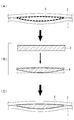
- the gaps between the members are filled by the following steps (see FIGS. 4A to 4C).
- the solid material 3 is machined according to the clearance shape, and the shim 4 is created.
- C) The shim 4 is inserted into the gap 5 to fill the gap between the joint surfaces.
- the shape of the gap is measured by an optical surface measurement, a gap measurement with a probe or the like, or a method of pouring in and solidifying a resin.
- An aluminum alloy, a resin or the like is used for the solid material 3.
- the present invention has been made in view of such circumstances, and omits a process of producing a shim by machining according to a measured clearance shape, and can provide a method of assembling a joining member which can make the assembling process more efficient, and It is an object of the present invention to provide a joint member assembled by
- the assembling method and joining member of the joining member of the present invention adopt the following means.
- At least one of a non-woven fabric composed of reinforcing fibers or a binder yarn composed of long fibers of reinforcing fibers joined by a bonding member as a base material is between members of a plurality of overlapped members.
- a method of assembling a bonding member comprises the steps of: inserting the base into a void; impregnating the base with a resin; and curing the resin within the void.
- a second aspect of the present invention comprises a plurality of stacked members, and a shim present to fill the members of the plurality of members, the shim including a substrate and a cured resin.
- the invention provides a bonding member in which the base material is at least one of a non-woven fabric made of reinforcing fibers and a binder yarn in which long fibers of the reinforcing fibers are connected by a bonding member.
- the gap between the members is filled by inserting the non-woven fabric or the binder yarn of the reinforcing fiber in the gap, and an excessive tensile load is applied to the fastening member and locally excessive deformation occurs in the fastened member. You can prevent that.
- Reinforcing fibers in sheet form such as non-woven fabrics and binder yarns can increase bonding strength as compared to chopped materials and the like.
- the non-woven fabric or the binder yarn follows the complicated three-dimensional shape in the air gap to maintain the shape of the joint member in which a plurality of members are jointed.
- the bonding surface can be corrected by filling and curing the resin in the void.
- the step of forming a shim by machining according to the measured gap shape is omitted by filling the void using a non-woven fabric or binder yarn of reinforcing fiber and a resin and curing the resin.
- the assembly process can be streamlined.
- the joining member includes a plurality of members which are overlapped and a shim which exists to fill the members of the plurality of members.
- the joining member further includes a fastening member for fastening the overlapped members.
- the members to be overlapped may be two or more. In the present embodiment, the members to be overlapped will be described as the first part and the second part.
- the first part and the second part are made of a fiber reinforced composite, an aluminum alloy or the like. Fiber reinforced composites are composed of matrix and reinforcing fibers.
- the matrix is a thermosetting resin such as epoxy resin, a thermoplastic resin such as PEEK (Poly Ether Ether Ketone), PEKK (Poly Ether Ketone Ketone), PPS (Poly Phenylene Sulfide), or the like.
- the reinforcing fiber is, for example, carbon fiber, glass fiber, or aramid fiber.
- Aluminum alloys include 2000 series and 7000 series. The thickness of the first part and the second part is about 0.5 mm to 50 mm.
- the shim comprises a substrate and a cured resin.
- the ratio of the base material to the resin in the shim may be adjusted within the range satisfying the strength or rigidity required for the bonding member.
- the proportion of the substrate is 80% by volume or less.
- the base material in the present embodiment is a non-woven fabric made of reinforcing fibers.
- the non-woven fabric is a sheet-like structure produced by fixing or entangled fibers mechanically, chemically, thermally or the like.
- the non-woven fabric has a predetermined length, for example, a length of several cm or more.
- the non-woven fabric has a thickness that can be inserted into the void.
- the thickness of the non-woven fabric is about 0.1 mm to 10 mm.
- a plurality of nonwoven fabrics may be piled up.
- the number of laminated non-woven fabrics can be appropriately set according to the change in the shape (plate thickness etc.) of the shims.
- the reinforcing fibers are carbon fibers, aramid fibers, glass fibers and the like.
- the fiber diameter and fiber length of the reinforcing fibers constituting the non-woven fabric do not necessarily have to be one type, and fibers of a plurality of types (diameter, length) may be mixed to constitute the non-woven fabric.
- the material of the resin may be any one that satisfies all of the strength, rigidity, toughness, durability, environmental resistance, etc. required for the application site.
- the material of the resin is epoxy resin, polyetheretherketone (PEEK) or the like.
- the resin may contain an appropriate filler (such as a chopped material or a powder material) to satisfy the required properties.
- the material of the filler is epoxy resin, polyetheretherketone (PEEK) or the like.
- the fastening member is a rivet, a bolt or the like.
- the fastening member is configured to penetrate the first member, the shim and the second member, and fastens the first member and the second member so as to enable load transfer between the members.
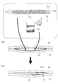
- FIG. 1 shows a flow diagram of a method of assembling the joining member according to the present embodiment.
- the base material 11 is impregnated with the resin 12.
- the impregnation of the resin can be carried out by coating with a brush, injection of the resin with a nozzle, or the like.
- the base material 11 impregnated with the resin 12 is inserted into the air gap 15 between the overlapped first part 13 and second part 14. After the insertion of the base 11, if there is a space, the resin 12 may be additionally replenished in the space.
- the resin 12 is cured to form a resin 12 ′ (see FIG. 1 (B)).
- a thermosetting resin such as an epoxy resin
- the first component 13 and the second component 14 are covered with a heater mat or the like so that the resin 12 has a curing temperature (for example, 90.degree. C. to 120.degree. C.).
- a thermoplastic resin such as PEEK
- the resin 12 is cooled to reach a curing temperature. The cooling may be allowing to cool, or may be actively performed using a cooling means such as a spot cooler.
- the first component 13 and the second component 14 are fastened by the fastening member.
- the fastening member fastens using a rivet, a bolt, etc. (not shown).
- the bonding strength of the bonding member can be improved by inserting the non-woven fabric made of the reinforcing fibers into the space.
- the non-woven fabric made of reinforcing fibers has shape flexibility and can be applied to the cavity 15 having a complicated three-dimensional shape.
- each component can be firmly supported between the first component 13 and the second component 14, and the shape of the joining member can be maintained.
- the bonding surface can be corrected by curing the resin 12 in the void. As a result, the space between the members can be reliably filled, and excessive tensile load on the fastening members and local over-deformation of the fastened members can be prevented.
- the assembling method of the present embodiment it is not necessary to measure the shape of the air gap 15 and machine the shim according to the shape, so that the assembling process can be made efficient.
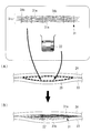
- FIG. 2 shows a flow diagram of the method of assembling the joining member according to the present embodiment.
- the base 21 in the present embodiment is a binder yarn.
- the binder yarn is a sheet-like structure in which the long fibers of the reinforcing fibers 21a are connected by a bonding member.
- the bonding member in FIG. 2 is an adhesive 21 b.
- the reinforcing fibers 21a are spread in a predetermined surface area and form a fiber layer 21c formed by being deposited in the thickness direction.
- the binder yarn of FIG. 2 is a sheet-like structure in which the resin 21b is attached to the surface of the long fibers of the reinforcing fiber 21a and the fibers are not separated.
- the material of the resin 21b is a thermosetting resin such as epoxy resin, or polyetheretherketone (PEEK).
- the resin 21 b is preferably made of the same material as the resin 22 for filling a gap described later.
- the thickness of the fiber layer 21c is preferably 0.1 mm to 10 mm. If the fiber layer 21c has a thickness within the above range, it becomes possible to conform to the size of the void by laminating a plurality of sheets.
- the fiber diameter and the fiber length of the reinforcing fiber 21a constituting the fiber layer 21c do not necessarily have to be one type, and fibers of a plurality of types (diameter, length) may be mixed to constitute the fiber layer 21c.
- the reinforcing fibers 21a are carbon fibers, aramid fibers, glass fibers or the like.
- the material of the resin 22 for filling the gaps between the members may be any material that satisfies all of the strength, rigidity, toughness, durability, environmental resistance, and the like required for the application site.
- the material of the resin 22 is epoxy resin, polyetheretherketone (PEEK) or the like.
- the resin 22 may contain an appropriate filler (such as a chopped material or a powder material) to satisfy the required characteristics.
- the base 21 is inserted into the air gap 25 between the first part 23 and the second part 24 which are overlapped.
- the resin 22 is injected into the space 25 into which the base material 21 is inserted, and the base material 21 is impregnated with the resin 22 and the space 25 is filled.
- the impregnation of the resin 22 can be performed by a method such as coating using a brush, injection of the resin using a nozzle, or the like.
- the binder yarn is inserted into the air gap, thereby reliably filling the air gap 25 between the members and preventing excessive tensile load on the fastening member and local over-deformation of the fastened member. be able to.
- Binder yarns have shape flexibility and can be applied to voids 25 having complex three-dimensional shapes.
- shape of the binder yarn By making the shape of the binder yarn follow the shape in the air gap, each component can be firmly supported between the first component 23 and the second component 24 and the shape of the joining member can be maintained.
- the bonding surface can be corrected by curing the resin 22 in the air gap 25. As a result, the space 25 between the members can be reliably filled, and excessive tensile load on the fastening members and local over-deformation of the fastened members can be prevented.
- the binder yarn 31 in FIG. 3 is a sheet-like structure assuming a method of collecting long fibers using out-of-plane direction yarns as a method of collecting long fibers of reinforcing fibers.
- the coupling member is an out-of-plane direction yarn 31 b.
- the out-of-plane direction yarn 31b penetrates in the thickness direction of the fiber layer 31c, and connects the reinforcing fibers 31a so as to sew the surface of the fiber layer 31c.
- the out-of-plane direction yarn 31 b is a fiber mainly made of a thermosetting resin or a thermoplastic resin. Specific examples include epoxy resin, polyetheretherketone (PEEK) and the like.
- the binder yarn 31 of FIG. 3 can be applied when assembling a joining member in the same manner as the binder yarn 21 of FIG.
- the air gap is between the two members, but the invention is not limited to this.
- the air gap may be, for example, a space sandwiched by three or more members.
Landscapes
- Engineering & Computer Science (AREA)
- General Engineering & Computer Science (AREA)
- Mechanical Engineering (AREA)
- Chemical & Material Sciences (AREA)
- Organic Chemistry (AREA)
- Standing Axle, Rod, Or Tube Structures Coupled By Welding, Adhesion, Or Deposition (AREA)
- Connection Of Plates (AREA)
- Lining Or Joining Of Plastics Or The Like (AREA)
- Sealing Material Composition (AREA)
- Adhesives Or Adhesive Processes (AREA)
Abstract
Le but de la présente invention concerne un procédé d'assemblage d'éléments joints, qui omet les étapes de création d'une cale qui est adaptée à la forme d'un espace mesuré par usinage et qui peut rendre une étape d'assemblage plus efficace, et un élément joint assemblé par ce procédé. Ce procédé d'assemblage d'éléments joints comprend : une étape d'insertion d'un matériau de base (11), qui est un tissu non tissé constitué de fibres de renforcement, dans un espace (15) entre un premier élément (13) et un deuxième élément (14) qui sont superposés ; une étape d'imprégnation d'une résine (12) dans le matériau de base (11) ; et une étape de durcissement de la résine (12) dans l'espace (15).
Applications Claiming Priority (2)
| Application Number | Priority Date | Filing Date | Title |
|---|---|---|---|
| JP2016090855A JP2017196834A (ja) | 2016-04-28 | 2016-04-28 | 接合部材の組立方法および接合部材 |
| JP2016-090855 | 2016-04-28 |
Publications (1)
| Publication Number | Publication Date |
|---|---|
| WO2017187920A1 true WO2017187920A1 (fr) | 2017-11-02 |
Family
ID=60161655
Family Applications (1)
| Application Number | Title | Priority Date | Filing Date |
|---|---|---|---|
| PCT/JP2017/014316 Ceased WO2017187920A1 (fr) | 2016-04-28 | 2017-04-06 | Procédé d'assemblage d'éléments joints et élément joint |
Country Status (2)
| Country | Link |
|---|---|
| JP (1) | JP2017196834A (fr) |
| WO (1) | WO2017187920A1 (fr) |
Citations (4)
| Publication number | Priority date | Publication date | Assignee | Title |
|---|---|---|---|---|
| JPS5541286A (en) * | 1978-09-20 | 1980-03-24 | Fujitsu Ltd | Adhesion method |
| JP2001270041A (ja) * | 2000-03-23 | 2001-10-02 | Spirulina Biological Lab Ltd | 複合体の製造方法 |
| JP2005279990A (ja) * | 2004-03-29 | 2005-10-13 | Toyota Boshoku Corp | レーザー溶接方法およびレーザー溶接構造 |
| JP2016065164A (ja) * | 2014-09-25 | 2016-04-28 | 京セラケミカル株式会社 | 熱膨張性接着シートおよび部品の接着方法 |
-
2016
- 2016-04-28 JP JP2016090855A patent/JP2017196834A/ja active Pending
-
2017
- 2017-04-06 WO PCT/JP2017/014316 patent/WO2017187920A1/fr not_active Ceased
Patent Citations (4)
| Publication number | Priority date | Publication date | Assignee | Title |
|---|---|---|---|---|
| JPS5541286A (en) * | 1978-09-20 | 1980-03-24 | Fujitsu Ltd | Adhesion method |
| JP2001270041A (ja) * | 2000-03-23 | 2001-10-02 | Spirulina Biological Lab Ltd | 複合体の製造方法 |
| JP2005279990A (ja) * | 2004-03-29 | 2005-10-13 | Toyota Boshoku Corp | レーザー溶接方法およびレーザー溶接構造 |
| JP2016065164A (ja) * | 2014-09-25 | 2016-04-28 | 京セラケミカル株式会社 | 熱膨張性接着シートおよび部品の接着方法 |
Also Published As
| Publication number | Publication date |
|---|---|
| JP2017196834A (ja) | 2017-11-02 |
Similar Documents
| Publication | Publication Date | Title |
|---|---|---|
| CA2769693C (fr) | Procede de moulage de parties composites complexes a l'aide d'un stratifie a fibre continue multidirectionnel prealablement assemble | |
| EP2921583B1 (fr) | Fabrication de stratifiés composites utilisant des préformes piquées temporairement | |
| EP2931497B1 (fr) | Rattachement de composants composites à l'aide d'une fusion de film thermoplastique basse température | |
| AU2015213272B2 (en) | Filament network for a composite structure | |
| CN103925267B (zh) | 一种复合材料与金属连接结构及形成所述连接结构的方法 | |
| US7727631B2 (en) | System and method of manufacture of multi-resin composite articles | |
| JP5920471B2 (ja) | 三次元繊維強化複合材及び三次元繊維強化複合材の製造方法 | |
| EP1406757B1 (fr) | Procede de fabrication de joints de structure en utilisant des preformes textiles tissees tridimensionnelles impregnees d'adhesif | |
| US20050186390A1 (en) | Z-pin closeout joint and method of assembly | |
| US9452588B2 (en) | Adjustable shim | |
| JPH02169237A (ja) | からみ合った横繊維を有するマトリックス結合プライを含む複合ラミネート及びその製造方法 | |
| KR101318312B1 (ko) | 섬유 강화 복합체 | |
| CN108621531B (zh) | 复合构造体的制造方法 | |
| CN101128307A (zh) | 纤维复合结构元件和用于制造纤维复合结构元件的方法 | |
| US5520999A (en) | Composite structures incorporating multiple resin-based systems | |
| Ramezani et al. | A study of the fracture mechanisms of hybrid carbon fiber reinforced polymer laminates reinforced by thin‐ply | |
| EP3705271B1 (fr) | Procédé pour le collage d'un matériau composite | |
| US5508096A (en) | Integral composite structure incorporating multiple resin-based systems and method of manufacture | |
| US10047465B2 (en) | Method for manufacturing a fiber composite component | |
| JP7382757B2 (ja) | プリフォーム、繊維強化樹脂複合材料及び繊維強化樹脂複合材料の製造方法 | |
| WO2017187920A1 (fr) | Procédé d'assemblage d'éléments joints et élément joint | |
| JP2008529849A (ja) | 繊維複合材料構造要素および繊維複合材料構造要素を製造する方法 | |
| JP6642918B2 (ja) | 接合部材の組立方法および接合部材 | |
| JP2021024918A (ja) | 繊維強化樹脂複合材料及び繊維強化樹脂複合材料の製造方法 | |
| JP2020193336A (ja) | 成形材料および成形品 |
Legal Events
| Date | Code | Title | Description |
|---|---|---|---|
| NENP | Non-entry into the national phase |
Ref country code: DE |
|
| 121 | Ep: the epo has been informed by wipo that ep was designated in this application |
Ref document number: 17789208 Country of ref document: EP Kind code of ref document: A1 |
|
| 122 | Ep: pct application non-entry in european phase |
Ref document number: 17789208 Country of ref document: EP Kind code of ref document: A1 |