WO2017187920A1 - 接合部材の組立方法および接合部材 - Google Patents
接合部材の組立方法および接合部材 Download PDFInfo
- Publication number
- WO2017187920A1 WO2017187920A1 PCT/JP2017/014316 JP2017014316W WO2017187920A1 WO 2017187920 A1 WO2017187920 A1 WO 2017187920A1 JP 2017014316 W JP2017014316 W JP 2017014316W WO 2017187920 A1 WO2017187920 A1 WO 2017187920A1
- Authority
- WO
- WIPO (PCT)
- Prior art keywords
- resin
- members
- gap
- base material
- fibers
- Prior art date
- Legal status (The legal status is an assumption and is not a legal conclusion. Google has not performed a legal analysis and makes no representation as to the accuracy of the status listed.)
- Ceased
Links
Images

Classifications
-
- B—PERFORMING OPERATIONS; TRANSPORTING
- B29—WORKING OF PLASTICS; WORKING OF SUBSTANCES IN A PLASTIC STATE IN GENERAL
- B29C—SHAPING OR JOINING OF PLASTICS; SHAPING OF MATERIAL IN A PLASTIC STATE, NOT OTHERWISE PROVIDED FOR; AFTER-TREATMENT OF THE SHAPED PRODUCTS, e.g. REPAIRING
- B29C65/00—Joining or sealing of preformed parts, e.g. welding of plastics materials; Apparatus therefor
- B29C65/48—Joining or sealing of preformed parts, e.g. welding of plastics materials; Apparatus therefor using adhesives, i.e. using supplementary joining material; solvent bonding
- B29C65/52—Joining or sealing of preformed parts, e.g. welding of plastics materials; Apparatus therefor using adhesives, i.e. using supplementary joining material; solvent bonding characterised by the way of applying the adhesive
-
- B—PERFORMING OPERATIONS; TRANSPORTING
- B29—WORKING OF PLASTICS; WORKING OF SUBSTANCES IN A PLASTIC STATE IN GENERAL
- B29C—SHAPING OR JOINING OF PLASTICS; SHAPING OF MATERIAL IN A PLASTIC STATE, NOT OTHERWISE PROVIDED FOR; AFTER-TREATMENT OF THE SHAPED PRODUCTS, e.g. REPAIRING
- B29C65/00—Joining or sealing of preformed parts, e.g. welding of plastics materials; Apparatus therefor
- B29C65/56—Joining or sealing of preformed parts, e.g. welding of plastics materials; Apparatus therefor using mechanical means or mechanical connections, e.g. form-fits
-
- C—CHEMISTRY; METALLURGY
- C09—DYES; PAINTS; POLISHES; NATURAL RESINS; ADHESIVES; COMPOSITIONS NOT OTHERWISE PROVIDED FOR; APPLICATIONS OF MATERIALS NOT OTHERWISE PROVIDED FOR
- C09J—ADHESIVES; NON-MECHANICAL ASPECTS OF ADHESIVE PROCESSES IN GENERAL; ADHESIVE PROCESSES NOT PROVIDED FOR ELSEWHERE; USE OF MATERIALS AS ADHESIVES
- C09J5/00—Adhesive processes in general; Adhesive processes not provided for elsewhere, e.g. relating to primers
-
- F—MECHANICAL ENGINEERING; LIGHTING; HEATING; WEAPONS; BLASTING
- F16—ENGINEERING ELEMENTS AND UNITS; GENERAL MEASURES FOR PRODUCING AND MAINTAINING EFFECTIVE FUNCTIONING OF MACHINES OR INSTALLATIONS; THERMAL INSULATION IN GENERAL
- F16B—DEVICES FOR FASTENING OR SECURING CONSTRUCTIONAL ELEMENTS OR MACHINE PARTS TOGETHER, e.g. NAILS, BOLTS, CIRCLIPS, CLAMPS, CLIPS OR WEDGES; JOINTS OR JOINTING
- F16B11/00—Connecting constructional elements or machine parts by sticking or pressing them together, e.g. cold pressure welding
-
- F—MECHANICAL ENGINEERING; LIGHTING; HEATING; WEAPONS; BLASTING
- F16—ENGINEERING ELEMENTS AND UNITS; GENERAL MEASURES FOR PRODUCING AND MAINTAINING EFFECTIVE FUNCTIONING OF MACHINES OR INSTALLATIONS; THERMAL INSULATION IN GENERAL
- F16B—DEVICES FOR FASTENING OR SECURING CONSTRUCTIONAL ELEMENTS OR MACHINE PARTS TOGETHER, e.g. NAILS, BOLTS, CIRCLIPS, CLAMPS, CLIPS OR WEDGES; JOINTS OR JOINTING
- F16B5/00—Joining sheets or plates, e.g. panels, to one another or to strips or bars parallel to them
- F16B5/08—Joining sheets or plates, e.g. panels, to one another or to strips or bars parallel to them by means of welds or the like
Definitions
- the present invention relates to a method of assembling a joining member and a joining member.
- Adhesives or fastening members are available as means for joining the two parts.
- Patent Document 1 an adhesive is introduced between parts to join two parts.
- Patent No. 4763196 (Claim 1)
- the members to be joined have shape tolerance due to the influence of shape accuracy up to the previous process.
- a gap is generated on the mating surface (joint surface) between the part and the part. If there is a gap between parts, an excessive tensile load may be applied to the fastening member at the time of fastening, or an excessive deformation may locally occur in the fastened member, which may lead to breakage.
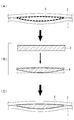
- the gaps between the members are filled by the following steps (see FIGS. 4A to 4C).
- the solid material 3 is machined according to the clearance shape, and the shim 4 is created.
- C) The shim 4 is inserted into the gap 5 to fill the gap between the joint surfaces.
- the shape of the gap is measured by an optical surface measurement, a gap measurement with a probe or the like, or a method of pouring in and solidifying a resin.
- An aluminum alloy, a resin or the like is used for the solid material 3.
- the present invention has been made in view of such circumstances, and omits a process of producing a shim by machining according to a measured clearance shape, and can provide a method of assembling a joining member which can make the assembling process more efficient, and It is an object of the present invention to provide a joint member assembled by
- the assembling method and joining member of the joining member of the present invention adopt the following means.
- At least one of a non-woven fabric composed of reinforcing fibers or a binder yarn composed of long fibers of reinforcing fibers joined by a bonding member as a base material is between members of a plurality of overlapped members.
- a method of assembling a bonding member comprises the steps of: inserting the base into a void; impregnating the base with a resin; and curing the resin within the void.
- a second aspect of the present invention comprises a plurality of stacked members, and a shim present to fill the members of the plurality of members, the shim including a substrate and a cured resin.
- the invention provides a bonding member in which the base material is at least one of a non-woven fabric made of reinforcing fibers and a binder yarn in which long fibers of the reinforcing fibers are connected by a bonding member.
- the gap between the members is filled by inserting the non-woven fabric or the binder yarn of the reinforcing fiber in the gap, and an excessive tensile load is applied to the fastening member and locally excessive deformation occurs in the fastened member. You can prevent that.
- Reinforcing fibers in sheet form such as non-woven fabrics and binder yarns can increase bonding strength as compared to chopped materials and the like.
- the non-woven fabric or the binder yarn follows the complicated three-dimensional shape in the air gap to maintain the shape of the joint member in which a plurality of members are jointed.
- the bonding surface can be corrected by filling and curing the resin in the void.
- the step of forming a shim by machining according to the measured gap shape is omitted by filling the void using a non-woven fabric or binder yarn of reinforcing fiber and a resin and curing the resin.
- the assembly process can be streamlined.
- the joining member includes a plurality of members which are overlapped and a shim which exists to fill the members of the plurality of members.
- the joining member further includes a fastening member for fastening the overlapped members.
- the members to be overlapped may be two or more. In the present embodiment, the members to be overlapped will be described as the first part and the second part.
- the first part and the second part are made of a fiber reinforced composite, an aluminum alloy or the like. Fiber reinforced composites are composed of matrix and reinforcing fibers.
- the matrix is a thermosetting resin such as epoxy resin, a thermoplastic resin such as PEEK (Poly Ether Ether Ketone), PEKK (Poly Ether Ketone Ketone), PPS (Poly Phenylene Sulfide), or the like.
- the reinforcing fiber is, for example, carbon fiber, glass fiber, or aramid fiber.
- Aluminum alloys include 2000 series and 7000 series. The thickness of the first part and the second part is about 0.5 mm to 50 mm.
- the shim comprises a substrate and a cured resin.
- the ratio of the base material to the resin in the shim may be adjusted within the range satisfying the strength or rigidity required for the bonding member.
- the proportion of the substrate is 80% by volume or less.
- the base material in the present embodiment is a non-woven fabric made of reinforcing fibers.
- the non-woven fabric is a sheet-like structure produced by fixing or entangled fibers mechanically, chemically, thermally or the like.
- the non-woven fabric has a predetermined length, for example, a length of several cm or more.
- the non-woven fabric has a thickness that can be inserted into the void.
- the thickness of the non-woven fabric is about 0.1 mm to 10 mm.
- a plurality of nonwoven fabrics may be piled up.
- the number of laminated non-woven fabrics can be appropriately set according to the change in the shape (plate thickness etc.) of the shims.
- the reinforcing fibers are carbon fibers, aramid fibers, glass fibers and the like.
- the fiber diameter and fiber length of the reinforcing fibers constituting the non-woven fabric do not necessarily have to be one type, and fibers of a plurality of types (diameter, length) may be mixed to constitute the non-woven fabric.
- the material of the resin may be any one that satisfies all of the strength, rigidity, toughness, durability, environmental resistance, etc. required for the application site.
- the material of the resin is epoxy resin, polyetheretherketone (PEEK) or the like.
- the resin may contain an appropriate filler (such as a chopped material or a powder material) to satisfy the required properties.
- the material of the filler is epoxy resin, polyetheretherketone (PEEK) or the like.
- the fastening member is a rivet, a bolt or the like.
- the fastening member is configured to penetrate the first member, the shim and the second member, and fastens the first member and the second member so as to enable load transfer between the members.
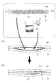
- FIG. 1 shows a flow diagram of a method of assembling the joining member according to the present embodiment.
- the base material 11 is impregnated with the resin 12.
- the impregnation of the resin can be carried out by coating with a brush, injection of the resin with a nozzle, or the like.
- the base material 11 impregnated with the resin 12 is inserted into the air gap 15 between the overlapped first part 13 and second part 14. After the insertion of the base 11, if there is a space, the resin 12 may be additionally replenished in the space.
- the resin 12 is cured to form a resin 12 ′ (see FIG. 1 (B)).
- a thermosetting resin such as an epoxy resin
- the first component 13 and the second component 14 are covered with a heater mat or the like so that the resin 12 has a curing temperature (for example, 90.degree. C. to 120.degree. C.).
- a thermoplastic resin such as PEEK
- the resin 12 is cooled to reach a curing temperature. The cooling may be allowing to cool, or may be actively performed using a cooling means such as a spot cooler.
- the first component 13 and the second component 14 are fastened by the fastening member.
- the fastening member fastens using a rivet, a bolt, etc. (not shown).
- the bonding strength of the bonding member can be improved by inserting the non-woven fabric made of the reinforcing fibers into the space.
- the non-woven fabric made of reinforcing fibers has shape flexibility and can be applied to the cavity 15 having a complicated three-dimensional shape.
- each component can be firmly supported between the first component 13 and the second component 14, and the shape of the joining member can be maintained.
- the bonding surface can be corrected by curing the resin 12 in the void. As a result, the space between the members can be reliably filled, and excessive tensile load on the fastening members and local over-deformation of the fastened members can be prevented.
- the assembling method of the present embodiment it is not necessary to measure the shape of the air gap 15 and machine the shim according to the shape, so that the assembling process can be made efficient.
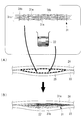
- FIG. 2 shows a flow diagram of the method of assembling the joining member according to the present embodiment.
- the base 21 in the present embodiment is a binder yarn.
- the binder yarn is a sheet-like structure in which the long fibers of the reinforcing fibers 21a are connected by a bonding member.
- the bonding member in FIG. 2 is an adhesive 21 b.
- the reinforcing fibers 21a are spread in a predetermined surface area and form a fiber layer 21c formed by being deposited in the thickness direction.
- the binder yarn of FIG. 2 is a sheet-like structure in which the resin 21b is attached to the surface of the long fibers of the reinforcing fiber 21a and the fibers are not separated.
- the material of the resin 21b is a thermosetting resin such as epoxy resin, or polyetheretherketone (PEEK).
- the resin 21 b is preferably made of the same material as the resin 22 for filling a gap described later.
- the thickness of the fiber layer 21c is preferably 0.1 mm to 10 mm. If the fiber layer 21c has a thickness within the above range, it becomes possible to conform to the size of the void by laminating a plurality of sheets.
- the fiber diameter and the fiber length of the reinforcing fiber 21a constituting the fiber layer 21c do not necessarily have to be one type, and fibers of a plurality of types (diameter, length) may be mixed to constitute the fiber layer 21c.
- the reinforcing fibers 21a are carbon fibers, aramid fibers, glass fibers or the like.
- the material of the resin 22 for filling the gaps between the members may be any material that satisfies all of the strength, rigidity, toughness, durability, environmental resistance, and the like required for the application site.
- the material of the resin 22 is epoxy resin, polyetheretherketone (PEEK) or the like.
- the resin 22 may contain an appropriate filler (such as a chopped material or a powder material) to satisfy the required characteristics.
- the base 21 is inserted into the air gap 25 between the first part 23 and the second part 24 which are overlapped.
- the resin 22 is injected into the space 25 into which the base material 21 is inserted, and the base material 21 is impregnated with the resin 22 and the space 25 is filled.
- the impregnation of the resin 22 can be performed by a method such as coating using a brush, injection of the resin using a nozzle, or the like.
- the binder yarn is inserted into the air gap, thereby reliably filling the air gap 25 between the members and preventing excessive tensile load on the fastening member and local over-deformation of the fastened member. be able to.
- Binder yarns have shape flexibility and can be applied to voids 25 having complex three-dimensional shapes.
- shape of the binder yarn By making the shape of the binder yarn follow the shape in the air gap, each component can be firmly supported between the first component 23 and the second component 24 and the shape of the joining member can be maintained.
- the bonding surface can be corrected by curing the resin 22 in the air gap 25. As a result, the space 25 between the members can be reliably filled, and excessive tensile load on the fastening members and local over-deformation of the fastened members can be prevented.
- the binder yarn 31 in FIG. 3 is a sheet-like structure assuming a method of collecting long fibers using out-of-plane direction yarns as a method of collecting long fibers of reinforcing fibers.
- the coupling member is an out-of-plane direction yarn 31 b.
- the out-of-plane direction yarn 31b penetrates in the thickness direction of the fiber layer 31c, and connects the reinforcing fibers 31a so as to sew the surface of the fiber layer 31c.
- the out-of-plane direction yarn 31 b is a fiber mainly made of a thermosetting resin or a thermoplastic resin. Specific examples include epoxy resin, polyetheretherketone (PEEK) and the like.
- the binder yarn 31 of FIG. 3 can be applied when assembling a joining member in the same manner as the binder yarn 21 of FIG.
- the air gap is between the two members, but the invention is not limited to this.
- the air gap may be, for example, a space sandwiched by three or more members.
Landscapes
- Engineering & Computer Science (AREA)
- General Engineering & Computer Science (AREA)
- Mechanical Engineering (AREA)
- Chemical & Material Sciences (AREA)
- Organic Chemistry (AREA)
- Standing Axle, Rod, Or Tube Structures Coupled By Welding, Adhesion, Or Deposition (AREA)
- Connection Of Plates (AREA)
- Lining Or Joining Of Plastics Or The Like (AREA)
- Sealing Material Composition (AREA)
- Adhesives Or Adhesive Processes (AREA)
Abstract
測定した隙間形状に合わせて機械加工によりシムを作成する工程を省略し、組立工程を効率化できる接合部材の組立方法およびそれにより組み立てられた接合部材を提供することを目的とする。本発明に係る接合部材の組立方法は、強化繊維で構成された不織布を基材(11)とし、重ね合せた第1部品(13)と第2部品(14)との間にある空隙(15)に基材(11)を挿入する工程と、基材(11)に樹脂(12)を含浸させる工程と、空隙(15)で樹脂(12)を硬化させる工程と、を備える。
Description
本発明は、接合部材の組立方法および接合部材に関するものである。
2つの部品を接合する手段として、接着剤または締結部材がある。特許文献1では、部品間に接着剤を導入して2つの部品を接合している。
しかしながら、接着剤のみで接合した部品は、接合強度の保証が難しい。よって、接合強度の保証が必要な部品や、接着剤が適用できない部品等の接合では締結部材が用いられる。
接合される各部材は、前工程までの形状精度による影響から形状公差がある。形状公差が大きい部品を重ね合せると、部品と部品との合せ面(接合面)に隙間が生じる。部品間に隙間があると、締結時に締結部材に過大な引張荷重がかかる、または、被締結部材に局所的に過大な変形が生じる等により破壊に至る恐れがある。
そのため、締結部材を用いて部品を組み立てる際には、締結作業前に部材間の隙間を埋める必要がある。
例えば、以下の工程により部材間の隙間を埋める(図4(A)から図4(C)参照)。
(A)まず、2つの部品(第1部品1,第2部品2)を重ね合せ、部品間の隙間形状を測定する。
(B)次に、隙間形状に合わせてソリッド材3を機械加工して、シム4を作成する。
(C)シム4を隙間5に挿入し、接合面間の隙間を埋める。
(A)まず、2つの部品(第1部品1,第2部品2)を重ね合せ、部品間の隙間形状を測定する。
(B)次に、隙間形状に合わせてソリッド材3を機械加工して、シム4を作成する。
(C)シム4を隙間5に挿入し、接合面間の隙間を埋める。
隙間形状は、光学的な面計測、プローブ等による隙間計測、または樹脂を流し込んで固めるなどの手法により測定する。ソリッド材3には、アルミニウム合金、樹脂などが用いられる。
上記のような方法は、非常に手間がかかり、労働集約的な方法である。
本発明は、このような事情に鑑みてなされたものであって、測定した隙間形状に合わせて機械加工によりシムを作成する工程を省略し、組立工程を効率化できる接合部材の組立方法およびそれにより組み立てられた接合部材を提供することを目的とする。
上記課題を解決するために、本発明の接合部材の組立方法および接合部材は以下の手段を採用する。
本発明の第1態様は、強化繊維で構成された不織布または、強化繊維の長繊維を結合部材で繋いでなるバインダーヤーンの少なくとも一方を基材とし、重ね合せた複数の部材の部材間にある空隙に前記基材を挿入する工程と、前記基材に樹脂を含浸させる工程と、前記空隙内で前記樹脂を硬化させる工程と、を備える接合部材の組立方法を提供する。
本発明の第2の態様は、重ね合せられた複数の部材と、前記複数の部材の部材間を埋めるよう存在するシムと、を備え、前記シムが、基材と硬化された樹脂とを含み、前記基材が、強化繊維で構成された不織布または、強化繊維の長繊維を結合部材で繋いでなるバインダーヤーンの少なくとも一方である接合部材を提供する。
上記態様によれば、空隙に強化繊維の不織布またはバインダーヤーンを挿入することで部材間の空隙を埋め、締結部材に過大な引張荷重がかかることおよび被締結部材に局所的に過大な変形が生じることを防ぐことができる。不織布およびバインダーヤーンのようなシート状の形態になった強化繊維は、チョップ材などと比較して接合強度を高めることができる。
不織布またはバインダーヤーンは、空隙内の複雑な立体形状に追従して、複数の部材を接合した接合部材の形状を保持する。空隙内に樹脂を充填して硬化させることで、接合面を修正できる。
本発明によれば、強化繊維の不織布またはバインダーヤーンと、樹脂とを用いて空隙を埋めて樹脂を硬化させることにより、測定した隙間形状に合わせて機械加工によりシムを作成する工程を省略し、組立工程を効率化できる。
〔第1実施形態〕
まず、本実施形態に係る組立方法で組み立てられた接合部材について説明する。接合部材は、重ね合せられた複数の部材と、当該複数の部材の部材間を埋めるよう存在するシムと、を備えている。接合部材は、さらに、重ね合せられた部材同士を締結する締結部材を備えている。
まず、本実施形態に係る組立方法で組み立てられた接合部材について説明する。接合部材は、重ね合せられた複数の部材と、当該複数の部材の部材間を埋めるよう存在するシムと、を備えている。接合部材は、さらに、重ね合せられた部材同士を締結する締結部材を備えている。
重ね合せられる部材は、2以上であればよい。本実施形態では、重ね合せられる部材が第1部品および第2部品であるとして説明する。第1部品および第2部品は、繊維強化複合材、アルミニウム合金などからなる。繊維強化複合材は、マトリックスおよび強化繊維で構成されている。マトリックスは、エポキシ樹脂などの熱硬化性樹脂、PEEK(Poly Ether Ether Ketone)、PEKK(Poly Ether Ketone Ketone)、PPS(Poly Phenylene Sulfide)などの熱可塑性樹脂などである。強化繊維は、炭素繊維、ガラス繊維、またはアラミド繊維などである。アルミニウム合金は、2000系、7000系などである。第1部品および第2部品の厚さは、0.5mmから50mm程度である。
シムは、基材と硬化された樹脂とを含む。シムにおける基材と樹脂との割合は、接合部材に要求される強度または剛性を満たす範囲内で調整すればよい。例えば、基材の割合は80体積%以下である。
本実施形態における基材は、強化繊維で構成された不織布である。不織布とは、機械的、化学的、熱的などにより繊維を固着したり、絡み合せたりして作製されたシート状の構造物である。
不織布は、所定の長さ、例えば数cm以上の長さを有する。不織布は、空隙に挿入可能な厚さを有する。不織布の厚さは0.1mmから10mm程度である。不織布は複数枚重ねられていてもよい。不織布の積層枚数は、シムの形状(板厚等)の変化に応じて適宜設定され得る。
強化繊維は、炭素繊維、アラミド繊維、ガラス繊維等である。
不織布を構成する強化繊維の繊維径及び繊維長は必ずしも一種類である必要はなく、複数の種類(径、長さ)の繊維を混ぜ合わせて不織布を構成してもよい。
樹脂の材質は、適用部位に要求される強度、剛性、靱性、耐久性、耐環境性などのすべてを満足するものであればよい。例えば、樹脂の材質は、エポキシ樹脂、ポリエーテルエーテルケトン(PEEK)などである。
樹脂は、要求特性を満足させるために、適切なフィラー(チョップ材またはパウダー材など)を含有してもよい。フィラーの材質は、エポキシ樹脂、ポリエーテルエーテルケトン(PEEK)などである。
締結部材は、リベット、ボルト等である。締結部材は、第1部材、シムおよび第2部材を貫通する形態で、部材間での荷重伝達を可能にするように第1部材および第2部材を締結している。
次に、本実施形態に係る接合部材の組立方法について説明する。図1に、本実施形態に係る接合部材の組立方法のフロー図を示す。
(樹脂含浸および基材の挿入:図1(A)参照)
まず、基材11に樹脂12を含浸させる。樹脂の含浸は、はけを用いての塗布、ノズルを用いた樹脂の注入などの方法で実施できる。
まず、基材11に樹脂12を含浸させる。樹脂の含浸は、はけを用いての塗布、ノズルを用いた樹脂の注入などの方法で実施できる。
次に、重ね合せた第1部品13と第2部品14との間にある空隙15に、樹脂12を含浸させた基材11を挿入する。基材11の挿入後、隙間がある場合には、空隙内に樹脂12を追加補充してもよい。
(樹脂の硬化:図1(B)参照)
空隙15に基材11および樹脂12を充填した後、樹脂12を硬化させて樹脂12’とする(図1(B)参照)。樹脂12にエポキシ樹脂などの熱硬化性樹脂を用いた場合、樹脂12が硬化温度(例えば90℃から120℃)となるよう第1部品13および第2部品14をヒータマット等で覆い加熱すればよい。樹脂12にPEEKなどの熱可塑性樹脂を用いた場合、樹脂12が硬化する温度に達するように冷却する。冷却は、放冷でもよいし、スポットクーラーなどの冷却手段を用いて積極的に実施してもよい。
空隙15に基材11および樹脂12を充填した後、樹脂12を硬化させて樹脂12’とする(図1(B)参照)。樹脂12にエポキシ樹脂などの熱硬化性樹脂を用いた場合、樹脂12が硬化温度(例えば90℃から120℃)となるよう第1部品13および第2部品14をヒータマット等で覆い加熱すればよい。樹脂12にPEEKなどの熱可塑性樹脂を用いた場合、樹脂12が硬化する温度に達するように冷却する。冷却は、放冷でもよいし、スポットクーラーなどの冷却手段を用いて積極的に実施してもよい。
(締結)
樹脂12を硬化させた後、締結部材で第1部品13と第2部品14を締結する。例えば、リベット、ボルト等を用いて締結する(不図示)。
樹脂12を硬化させた後、締結部材で第1部品13と第2部品14を締結する。例えば、リベット、ボルト等を用いて締結する(不図示)。
本実施形態の組立方法によれば、強化繊維で構成された不織布を空隙に挿入することで、接合部材の接合強度を向上させられる。
強化繊維で構成された不織布は形状柔軟性を有し、複雑な立体形状を有する空隙15にも適用できる。不織布の形状を空隙内の形状に追従させることで、第1部品13と第2部品14との間でしっかりと各部品を支え、接合部材の形状を保持できる。空隙内で樹脂12を硬化させることで接合面を修正できる。それにより、部材間の空隙を確実に埋め、締結部材への過大な引張荷重および被締結部材の局所的な過大変形を防ぐことができる。
本実施形態の組立方法によれば、空隙15の形状を測定して、該形状に合わせてシムを機械加工により作成する工程が不要であり、組立工程を効率化できる。
〔第2実施形態〕
本実施形態は、基材にバインダーヤーンを用いている点が第1実施形態と異なる。本実施形態は、樹脂を含浸させるタイミングが第1実施形態と異なる。第1実施形態と同様の構成については説明を省略する。図2に、本実施形態に係る接合部材の組立方法のフロー図を示す。
本実施形態は、基材にバインダーヤーンを用いている点が第1実施形態と異なる。本実施形態は、樹脂を含浸させるタイミングが第1実施形態と異なる。第1実施形態と同様の構成については説明を省略する。図2に、本実施形態に係る接合部材の組立方法のフロー図を示す。
本実施形態における基材21は、バインダーヤーンである。バインダーヤーンは、強化繊維21aの長繊維を結合部材で繋いでなるシート状の構造物である。図2において結合部材は、接着剤21bである。強化繊維21aは、所定面領域に広げられるとともに、厚さ方向に堆積してなる繊維層21cを形成する。
図2のバインダーヤーンは、強化繊維21aの長繊維の表面に樹脂21bを付着させ、繊維同士がばらばらにならないようにまとめたシート状の構造物である。樹脂21bの材質は、エポキシ樹脂等の熱硬化性樹脂、またはポリエーテルエーテルケトン(PEEK)等である。樹脂21bは、後述する空隙を埋めるための樹脂22と同じ材質であることが好ましい。
繊維層21cの厚さは、0.1mmから10mmとするのが好ましい。繊維層21cが上記範囲内の厚さであれば、複数枚積層させることで空隙のサイズに適合させることが可能となる。
繊維層21cを構成する強化繊維21aの繊維径及び繊維長は必ずしも一種類である必要はなく、複数の種類(径、長さ)の繊維を混ぜ合わせて繊維層21cを構成してもよい。
強化繊維21aは、炭素繊維、アラミド繊維、ガラス繊維等である。
部材間の空隙を埋めるための樹脂22の材質は、適用部位に要求される強度、剛性、靱性、耐久性、耐環境性などのすべてを満足するものであればよい。例えば、樹脂22の材質は、エポキシ樹脂、ポリエーテルエーテルケトン(PEEK)などである。樹脂22は、要求特性を満足させるために、適切なフィラー(チョップ材またはパウダー材など)を含有してもよい。
次に、本実施形態に係る接合部材の組立方法について説明する。
(基材の挿入および樹脂の含浸:図2(A)参照)
まず、重ね合せた第1部品23と第2部品24との間にある空隙25に、基材21を挿入する。基材21を挿入した空隙25に樹脂22を注入し、基材21に樹脂22を含浸させるとともに空隙25を埋める。樹脂22の含浸は、はけを用いての塗布、ノズルを用いた樹脂の注入などの方法で実施できる。
まず、重ね合せた第1部品23と第2部品24との間にある空隙25に、基材21を挿入する。基材21を挿入した空隙25に樹脂22を注入し、基材21に樹脂22を含浸させるとともに空隙25を埋める。樹脂22の含浸は、はけを用いての塗布、ノズルを用いた樹脂の注入などの方法で実施できる。
(樹脂の硬化:図2(B)参照)
空隙25に基材21および樹脂22を充填した後、樹脂22を硬化させて樹脂22’とする。硬化は第1実施形態と同様に実施できる。
空隙25に基材21および樹脂22を充填した後、樹脂22を硬化させて樹脂22’とする。硬化は第1実施形態と同様に実施できる。
本実施形態の組立方法によれば、バインダーヤーンを空隙に挿入することで、部材間の空隙25を確実に埋め、締結部材への過大な引張荷重および被締結部材の局所的な過大変形を防ぐことができる。
バインダーヤーンは形状柔軟性を有し、複雑な立体形状を有する空隙25にも適用できる。バインダーヤーンの形状を空隙内の形状に追従させることで、第1部品23と第2部品24との間でしっかりと各部品を支え、接合部材の形状を保持できる。空隙25内で樹脂22を硬化させることで接合面を修正できる。それにより、部材間の空隙25を確実に埋め、締結部材への過大な引張荷重および被締結部材の局所的な過大変形を防ぐことができる。
本実施形態の組立方法によれば、空隙25の形状を測定して、該形状に合わせてシムを機械加工により作成する工程が不要であり、組立工程を効率化できる。
(変形例)
図3に、本実施形態の変形例を示す。図3のバインダーヤーン31は、強化繊維の長繊維のまとめ方として、面外方向糸を用いて長繊維をまとめる方法を想定したシート状の構造物である。図3において結合部材は、面外方向糸31bである。図3の通り、面外方向糸31bは、繊維層31cの厚さ方向に貫通し、繊維層31cの面を縫うようにして強化繊維31aを繋いでいる。
図3に、本実施形態の変形例を示す。図3のバインダーヤーン31は、強化繊維の長繊維のまとめ方として、面外方向糸を用いて長繊維をまとめる方法を想定したシート状の構造物である。図3において結合部材は、面外方向糸31bである。図3の通り、面外方向糸31bは、繊維層31cの厚さ方向に貫通し、繊維層31cの面を縫うようにして強化繊維31aを繋いでいる。
面外方向糸31bは、主に熱硬化性樹脂または熱可塑性樹脂からなる繊維である。具体例としては、エポキシ樹脂、ポリエーテルエーテルケトン(PEEK)などが挙げられる。
図3のバインダーヤーン31は、図2のバインダーヤーン21と同様に接合部材を組み立てる際に適用できる。
なお、第1実施形態と第2実施形態で用いる基材を入れ替える、または基材として不織布およびバインダーヤーンを組み合わせて使用してもよい。
なお、上記第1実施形態および第2実施形態では、空隙は2つの部材間にあるとしたが、これに限定されるものではない。空隙は、例えば3つ以上の部材に挟まれた空間であってもよい。
1,13,23 第1部品
2,14,24 第2部品
3 ソリッド材
4 (ソリッド材から機械加工により作成した)シム
5,15,25 隙間(空隙)
11 不織布(基材)
12,22 樹脂(硬化前)
12’,22’ 樹脂(硬化後)
21,31 バインダーヤーン(基材)
21a,31a 強化繊維
21b 接着剤(結合部材)
21c,31c 繊維層
31b 面外方向糸(結合部材)
2,14,24 第2部品
3 ソリッド材
4 (ソリッド材から機械加工により作成した)シム
5,15,25 隙間(空隙)
11 不織布(基材)
12,22 樹脂(硬化前)
12’,22’ 樹脂(硬化後)
21,31 バインダーヤーン(基材)
21a,31a 強化繊維
21b 接着剤(結合部材)
21c,31c 繊維層
31b 面外方向糸(結合部材)
Claims (2)
- 強化繊維で構成された不織布または、強化繊維の長繊維を結合部材で繋いでなるバインダーヤーンの少なくとも一方を基材とし、重ね合せた複数の部材の部材間にある空隙に前記基材を挿入する工程と、
前記基材に樹脂を含浸させる工程と、
前記空隙内で前記樹脂を硬化させる工程と、
を備える接合部材の組立方法。 - 重ね合せられた複数の部材と、
前記複数の部材の部材間を埋めるよう存在するシムと、
を備え、
前記シムが、基材と硬化された樹脂とを含み、
前記基材が、強化繊維で構成された不織布または、強化繊維の長繊維を結合部材で繋いでなるバインダーヤーンの少なくとも一方である接合部材。
Applications Claiming Priority (2)
| Application Number | Priority Date | Filing Date | Title |
|---|---|---|---|
| JP2016090855A JP2017196834A (ja) | 2016-04-28 | 2016-04-28 | 接合部材の組立方法および接合部材 |
| JP2016-090855 | 2016-04-28 |
Publications (1)
| Publication Number | Publication Date |
|---|---|
| WO2017187920A1 true WO2017187920A1 (ja) | 2017-11-02 |
Family
ID=60161655
Family Applications (1)
| Application Number | Title | Priority Date | Filing Date |
|---|---|---|---|
| PCT/JP2017/014316 Ceased WO2017187920A1 (ja) | 2016-04-28 | 2017-04-06 | 接合部材の組立方法および接合部材 |
Country Status (2)
| Country | Link |
|---|---|
| JP (1) | JP2017196834A (ja) |
| WO (1) | WO2017187920A1 (ja) |
Citations (4)
| Publication number | Priority date | Publication date | Assignee | Title |
|---|---|---|---|---|
| JPS5541286A (en) * | 1978-09-20 | 1980-03-24 | Fujitsu Ltd | Adhesion method |
| JP2001270041A (ja) * | 2000-03-23 | 2001-10-02 | Spirulina Biological Lab Ltd | 複合体の製造方法 |
| JP2005279990A (ja) * | 2004-03-29 | 2005-10-13 | Toyota Boshoku Corp | レーザー溶接方法およびレーザー溶接構造 |
| JP2016065164A (ja) * | 2014-09-25 | 2016-04-28 | 京セラケミカル株式会社 | 熱膨張性接着シートおよび部品の接着方法 |
-
2016
- 2016-04-28 JP JP2016090855A patent/JP2017196834A/ja active Pending
-
2017
- 2017-04-06 WO PCT/JP2017/014316 patent/WO2017187920A1/ja not_active Ceased
Patent Citations (4)
| Publication number | Priority date | Publication date | Assignee | Title |
|---|---|---|---|---|
| JPS5541286A (en) * | 1978-09-20 | 1980-03-24 | Fujitsu Ltd | Adhesion method |
| JP2001270041A (ja) * | 2000-03-23 | 2001-10-02 | Spirulina Biological Lab Ltd | 複合体の製造方法 |
| JP2005279990A (ja) * | 2004-03-29 | 2005-10-13 | Toyota Boshoku Corp | レーザー溶接方法およびレーザー溶接構造 |
| JP2016065164A (ja) * | 2014-09-25 | 2016-04-28 | 京セラケミカル株式会社 | 熱膨張性接着シートおよび部品の接着方法 |
Also Published As
| Publication number | Publication date |
|---|---|
| JP2017196834A (ja) | 2017-11-02 |
Similar Documents
| Publication | Publication Date | Title |
|---|---|---|
| CA2769693C (en) | Method of molding complex composite parts using pre-plied multi-directional continuous fiber laminate | |
| EP2921583B1 (en) | Method of fabricating a composite structure using temporarily stitched preforms, and composite preform | |
| EP2931497B1 (en) | Joining composite components using low temperature thermoplastic film fusion | |
| AU2015213272B2 (en) | Filament network for a composite structure | |
| CN103925267B (zh) | 一种复合材料与金属连接结构及形成所述连接结构的方法 | |
| US7727631B2 (en) | System and method of manufacture of multi-resin composite articles | |
| JP5920471B2 (ja) | 三次元繊維強化複合材及び三次元繊維強化複合材の製造方法 | |
| EP1406757B1 (en) | Method of producing structural joints using adhesive-infused 3-d woven textile preforms | |
| US20050186390A1 (en) | Z-pin closeout joint and method of assembly | |
| US9452588B2 (en) | Adjustable shim | |
| JPH02169237A (ja) | からみ合った横繊維を有するマトリックス結合プライを含む複合ラミネート及びその製造方法 | |
| KR101318312B1 (ko) | 섬유 강화 복합체 | |
| CN108621531B (zh) | 复合构造体的制造方法 | |
| CN101128307A (zh) | 纤维复合结构元件和用于制造纤维复合结构元件的方法 | |
| US5520999A (en) | Composite structures incorporating multiple resin-based systems | |
| Ramezani et al. | A study of the fracture mechanisms of hybrid carbon fiber reinforced polymer laminates reinforced by thin‐ply | |
| EP3705271B1 (en) | Method for bonding composite material | |
| US5508096A (en) | Integral composite structure incorporating multiple resin-based systems and method of manufacture | |
| US10047465B2 (en) | Method for manufacturing a fiber composite component | |
| JP7382757B2 (ja) | プリフォーム、繊維強化樹脂複合材料及び繊維強化樹脂複合材料の製造方法 | |
| WO2017187920A1 (ja) | 接合部材の組立方法および接合部材 | |
| JP2008529849A (ja) | 繊維複合材料構造要素および繊維複合材料構造要素を製造する方法 | |
| JP6642918B2 (ja) | 接合部材の組立方法および接合部材 | |
| JP2021024918A (ja) | 繊維強化樹脂複合材料及び繊維強化樹脂複合材料の製造方法 | |
| JP2020193336A (ja) | 成形材料および成形品 |
Legal Events
| Date | Code | Title | Description |
|---|---|---|---|
| NENP | Non-entry into the national phase |
Ref country code: DE |
|
| 121 | Ep: the epo has been informed by wipo that ep was designated in this application |
Ref document number: 17789208 Country of ref document: EP Kind code of ref document: A1 |
|
| 122 | Ep: pct application non-entry in european phase |
Ref document number: 17789208 Country of ref document: EP Kind code of ref document: A1 |