WO2017191695A1 - Système de distribution - Google Patents
Système de distribution Download PDFInfo
- Publication number
- WO2017191695A1 WO2017191695A1 PCT/JP2017/003157 JP2017003157W WO2017191695A1 WO 2017191695 A1 WO2017191695 A1 WO 2017191695A1 JP 2017003157 W JP2017003157 W JP 2017003157W WO 2017191695 A1 WO2017191695 A1 WO 2017191695A1
- Authority
- WO
- WIPO (PCT)
- Prior art keywords
- delivery
- box
- carriage
- delivery box
- destination
- Prior art date
- Legal status (The legal status is an assumption and is not a legal conclusion. Google has not performed a legal analysis and makes no representation as to the accuracy of the status listed.)
- Ceased
Links
Images









Classifications
-
- G—PHYSICS
- G06—COMPUTING OR CALCULATING; COUNTING
- G06Q—INFORMATION AND COMMUNICATION TECHNOLOGY [ICT] SPECIALLY ADAPTED FOR ADMINISTRATIVE, COMMERCIAL, FINANCIAL, MANAGERIAL OR SUPERVISORY PURPOSES; SYSTEMS OR METHODS SPECIALLY ADAPTED FOR ADMINISTRATIVE, COMMERCIAL, FINANCIAL, MANAGERIAL OR SUPERVISORY PURPOSES, NOT OTHERWISE PROVIDED FOR
- G06Q10/00—Administration; Management
- G06Q10/08—Logistics, e.g. warehousing, loading or distribution; Inventory or stock management
-
- G—PHYSICS
- G05—CONTROLLING; REGULATING
- G05D—SYSTEMS FOR CONTROLLING OR REGULATING NON-ELECTRIC VARIABLES
- G05D1/00—Control of position, course, altitude or attitude of land, water, air or space vehicles, e.g. using automatic pilots
- G05D1/0011—Control of position, course, altitude or attitude of land, water, air or space vehicles, e.g. using automatic pilots associated with a remote control arrangement
- G05D1/0027—Control of position, course, altitude or attitude of land, water, air or space vehicles, e.g. using automatic pilots associated with a remote control arrangement involving a plurality of vehicles, e.g. fleet or convoy travelling
-
- B—PERFORMING OPERATIONS; TRANSPORTING
- B60—VEHICLES IN GENERAL
- B60P—VEHICLES ADAPTED FOR LOAD TRANSPORTATION OR TO TRANSPORT, TO CARRY, OR TO COMPRISE SPECIAL LOADS OR OBJECTS
- B60P3/00—Vehicles adapted to transport, to carry or to comprise special loads or objects
-
- B—PERFORMING OPERATIONS; TRANSPORTING
- B61—RAILWAYS
- B61B—RAILWAY SYSTEMS; EQUIPMENT THEREFOR NOT OTHERWISE PROVIDED FOR
- B61B13/00—Other railway systems
-
- B—PERFORMING OPERATIONS; TRANSPORTING
- B65—CONVEYING; PACKING; STORING; HANDLING THIN OR FILAMENTARY MATERIAL
- B65G—TRANSPORT OR STORAGE DEVICES, e.g. CONVEYORS FOR LOADING OR TIPPING, SHOP CONVEYOR SYSTEMS OR PNEUMATIC TUBE CONVEYORS
- B65G1/00—Storing articles, individually or in orderly arrangement, in warehouses or magazines
- B65G1/02—Storage devices
- B65G1/04—Storage devices mechanical
- B65G1/06—Storage devices mechanical with means for presenting articles for removal at predetermined position or level
-
- B—PERFORMING OPERATIONS; TRANSPORTING
- B65—CONVEYING; PACKING; STORING; HANDLING THIN OR FILAMENTARY MATERIAL
- B65G—TRANSPORT OR STORAGE DEVICES, e.g. CONVEYORS FOR LOADING OR TIPPING, SHOP CONVEYOR SYSTEMS OR PNEUMATIC TUBE CONVEYORS
- B65G61/00—Use of pick-up or transfer devices or of manipulators for stacking or de-stacking articles not otherwise provided for
-
- G—PHYSICS
- G01—MEASURING; TESTING
- G01C—MEASURING DISTANCES, LEVELS OR BEARINGS; SURVEYING; NAVIGATION; GYROSCOPIC INSTRUMENTS; PHOTOGRAMMETRY OR VIDEOGRAMMETRY
- G01C21/00—Navigation; Navigational instruments not provided for in groups G01C1/00 - G01C19/00
- G01C21/20—Instruments for performing navigational calculations
- G01C21/206—Instruments for performing navigational calculations specially adapted for indoor navigation
-
- G—PHYSICS
- G01—MEASURING; TESTING
- G01C—MEASURING DISTANCES, LEVELS OR BEARINGS; SURVEYING; NAVIGATION; GYROSCOPIC INSTRUMENTS; PHOTOGRAMMETRY OR VIDEOGRAMMETRY
- G01C21/00—Navigation; Navigational instruments not provided for in groups G01C1/00 - G01C19/00
- G01C21/26—Navigation; Navigational instruments not provided for in groups G01C1/00 - G01C19/00 specially adapted for navigation in a road network
- G01C21/34—Route searching; Route guidance
- G01C21/3453—Special cost functions, i.e. other than distance or default speed limit of road segments
- G01C21/3492—Special cost functions, i.e. other than distance or default speed limit of road segments employing speed data or traffic data, e.g. real-time or historical
-
- G—PHYSICS
- G05—CONTROLLING; REGULATING
- G05D—SYSTEMS FOR CONTROLLING OR REGULATING NON-ELECTRIC VARIABLES
- G05D1/00—Control of position, course, altitude or attitude of land, water, air or space vehicles, e.g. using automatic pilots
- G05D1/02—Control of position or course in two dimensions
- G05D1/021—Control of position or course in two dimensions specially adapted to land vehicles
- G05D1/0287—Control of position or course in two dimensions specially adapted to land vehicles involving a plurality of land vehicles, e.g. fleet or convoy travelling
- G05D1/0291—Fleet control
- G05D1/0297—Fleet control by controlling means in a control room
-
- G—PHYSICS
- G06—COMPUTING OR CALCULATING; COUNTING
- G06Q—INFORMATION AND COMMUNICATION TECHNOLOGY [ICT] SPECIALLY ADAPTED FOR ADMINISTRATIVE, COMMERCIAL, FINANCIAL, MANAGERIAL OR SUPERVISORY PURPOSES; SYSTEMS OR METHODS SPECIALLY ADAPTED FOR ADMINISTRATIVE, COMMERCIAL, FINANCIAL, MANAGERIAL OR SUPERVISORY PURPOSES, NOT OTHERWISE PROVIDED FOR
- G06Q10/00—Administration; Management
- G06Q10/04—Forecasting or optimisation specially adapted for administrative or management purposes, e.g. linear programming or "cutting stock problem"
-
- G—PHYSICS
- G06—COMPUTING OR CALCULATING; COUNTING
- G06Q—INFORMATION AND COMMUNICATION TECHNOLOGY [ICT] SPECIALLY ADAPTED FOR ADMINISTRATIVE, COMMERCIAL, FINANCIAL, MANAGERIAL OR SUPERVISORY PURPOSES; SYSTEMS OR METHODS SPECIALLY ADAPTED FOR ADMINISTRATIVE, COMMERCIAL, FINANCIAL, MANAGERIAL OR SUPERVISORY PURPOSES, NOT OTHERWISE PROVIDED FOR
- G06Q10/00—Administration; Management
- G06Q10/08—Logistics, e.g. warehousing, loading or distribution; Inventory or stock management
- G06Q10/083—Shipping
-
- B—PERFORMING OPERATIONS; TRANSPORTING
- B65—CONVEYING; PACKING; STORING; HANDLING THIN OR FILAMENTARY MATERIAL
- B65G—TRANSPORT OR STORAGE DEVICES, e.g. CONVEYORS FOR LOADING OR TIPPING, SHOP CONVEYOR SYSTEMS OR PNEUMATIC TUBE CONVEYORS
- B65G1/00—Storing articles, individually or in orderly arrangement, in warehouses or magazines
- B65G1/02—Storage devices
- B65G1/04—Storage devices mechanical
- B65G1/0478—Storage devices mechanical for matrix-arrangements
-
- B—PERFORMING OPERATIONS; TRANSPORTING
- B65—CONVEYING; PACKING; STORING; HANDLING THIN OR FILAMENTARY MATERIAL
- B65G—TRANSPORT OR STORAGE DEVICES, e.g. CONVEYORS FOR LOADING OR TIPPING, SHOP CONVEYOR SYSTEMS OR PNEUMATIC TUBE CONVEYORS
- B65G1/00—Storing articles, individually or in orderly arrangement, in warehouses or magazines
- B65G1/02—Storage devices
- B65G1/04—Storage devices mechanical
- B65G1/12—Storage devices mechanical with separate article supports or holders movable in a closed circuit to facilitate insertion or removal of articles the articles being books, documents, forms or the like
- B65G1/133—Storage devices mechanical with separate article supports or holders movable in a closed circuit to facilitate insertion or removal of articles the articles being books, documents, forms or the like the circuit being confined in a horizontal plane
-
- B—PERFORMING OPERATIONS; TRANSPORTING
- B65—CONVEYING; PACKING; STORING; HANDLING THIN OR FILAMENTARY MATERIAL
- B65G—TRANSPORT OR STORAGE DEVICES, e.g. CONVEYORS FOR LOADING OR TIPPING, SHOP CONVEYOR SYSTEMS OR PNEUMATIC TUBE CONVEYORS
- B65G1/00—Storing articles, individually or in orderly arrangement, in warehouses or magazines
- B65G1/02—Storage devices
- B65G1/04—Storage devices mechanical
- B65G1/137—Storage devices mechanical with arrangements or automatic control means for selecting which articles are to be removed
- B65G1/1373—Storage devices mechanical with arrangements or automatic control means for selecting which articles are to be removed for fulfilling orders in warehouses
- B65G1/1375—Storage devices mechanical with arrangements or automatic control means for selecting which articles are to be removed for fulfilling orders in warehouses the orders being assembled on a commissioning stacker-crane or truck
Definitions
- the present invention relates to a delivery system.
- This EC site plays a role as a virtual store provided on the Web and is also called an online shop.
- a product is selected on the EC site, it is possible to purchase the product, complete personal authentication, payment procedure, etc. on a system called a Web payment system, and then deliver the product to a designated delivery destination. .
- the products at this time include “digital data” distributed online and “shape products (articles)” such as daily necessities.
- delivery of the product is completed if it is sent to a designated destination such as an e-mail, but when the latter “shaped product” is purchased, And delivered (delivered) to a delivery destination via a delivery company or the like. That is, in the latter case, a delivery process for delivering the product to the delivery destination is necessary.
- Patent Document 1 discloses a technique related to a transportation device with a three-dimensional automatic warehouse.
- the transportation apparatus with a three-dimensional automatic warehouse of Patent Document 1 includes a rack, a stacker crane, a restraint mechanism for restraining the stacker crane, and a control means, and mechanizes the storage and handling of goods to reduce the burden on the operator. .
- the present invention has been made in view of the above circumstances, and an object of the present invention is to solve the above-described problems. That is, an example of the subject of this invention is providing the delivery system which can deliver a package efficiently.
- a delivery system includes a delivery vehicle that can load delivery boxes to be delivered to a delivery destination, a storage that can store one or a plurality of delivery boxes, and can be equipped with the delivery vehicle.
- a mother vehicle, and the mother vehicle includes a transport control mechanism for transporting the delivery box disposed at a predetermined storage position in the storage to another storage position different from the predetermined storage position.
- the delivery vehicle receives the delivery box, which is transported and controlled by the transport control mechanism, from the mother vehicle with respect to the receiving storage position where the delivery box can be received among the storage positions.
- the shipping box became mounting state is delivered to the delivery destination.
- a delivery system includes a delivery vehicle on which a delivery box to be delivered to a delivery destination is loaded, and a mother vehicle on which the delivery vehicle is mounted.
- the mother vehicle includes a plurality of delivery boxes.
- the automatic warehouse configured to store and change the arrangement of the plurality of delivery boxes, and to the delivery destination before the delivery vehicle is dismounted at a relay point on the delivery route from the delivery source to the delivery destination.
- the delivery box to be delivered includes a control unit that controls the automatic warehouse so that the delivery vehicle is disposed at a receiving storage position where the delivery vehicle can receive the delivery box, and the delivery box is located at the relay point corresponding to the delivery destination.
- the delivery vehicle loaded with the delivery box to be delivered to the delivery destination is dismounted, and the delivery vehicle receives the delivery box arranged at the receiving and storing position.
- the delivery box to be delivered to the delivery destination is loaded, travels on the delivery route from the relay point to the delivery destination, and the delivery box loaded on the delivery vehicle is set to the delivery destination. to deliver.
- the delivery system according to one aspect of the present invention can deliver packages efficiently.
- FIG. 7 is a diagram showing an internal configuration of a storage included in the automatic warehouse according to the first embodiment of the present invention, and is a view taken along the line AA ′ when the storage is cut along the line AA ′ shown in FIG. 6.
- the figure which shows the conveyor which comprises the conveyance control mechanism contained in the automatic warehouse in Embodiment 1 of this invention.
- the figure which shows the delivery aspect in the delivery system in Embodiment 1 of this invention (the 1).
- the figure which shows the delivery aspect in the delivery system in Embodiment 1 of this invention (the 2).
- the figure which shows the delivery aspect in the delivery system in Embodiment 1 of this invention (the 3).
- the figure which shows the delivery aspect in the delivery system in Embodiment 1 of this invention (the 4).
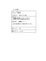
- the figure which shows the engagement state of the delivery box and delivery box fixing tool in Embodiment 1 of this invention The figure which shows the mail content which the recipient of a package receives.
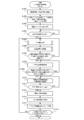
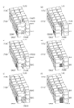
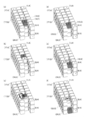
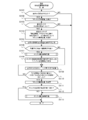
- the flowchart which shows the detailed flow of the transfer control process between tiers performed in the mother wheel and the child car in Embodiment 1 of this invention. It is a figure which shows a mode that arrangement
- FIG. 1 It is a figure which shows typically a mode that arrangement
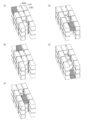
- Figure. The figure which shows the delivery box in Embodiment 2 of this invention, and its arrangement
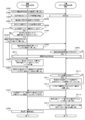
- the flowchart which shows the detailed flow of the automatic warehouse control process performed in the mother carriage in Embodiment 3 of this invention.
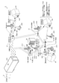
- FIG. 1 is a diagram showing an overview of a delivery system 1 in Embodiment 1 of the present invention.
- the delivery system 1 delivers a package by moving a delivery vehicle from a delivery center (hereinafter also referred to as “center 10”), which is a “delivery source” of the package, to a “delivery destination 20 (delivery destination)”.
- center 10 a delivery center
- delivery destination 20 delivery destination
- the center 10 includes a product management center (product management source) that manages products, a delivery center (delivery source) that performs delivery procedures for products ordered by the purchaser among products managed in the product management center, and monitoring related to delivery. It is a general term for bases that play a role such as a monitoring center (monitoring source).
- the center 10 may also be referred to as a “delivery base”.
- the center 10 accepts orders made using an EC site where electronic commerce is possible. More specifically, the center 10 receives an order at a server provided in the center 10 that manages and operates an EC site.
- This EC site is a store on the Web that can be accessed using electronic devices such as personal computers and tablets installed at home. A person who wishes to purchase a product can easily order (purchase) the desired product by accessing the EC site, and can easily shop.
- Access to this EC site is also possible from a vending machine equipped with a liquid crystal display and connected to the website via network communication.
- a person who wants to purchase a product can purchase the product displayed on the liquid crystal display like a beverage purchased by a conventional vending machine.
- the person who wishes to purchase the product designates the product to be purchased together with the payment method of the product and the delivery destination 20 of the product.
- the ordered product is selected from the managed products and the product is delivered to the delivery destination 20.
- the goods are delivered as a package by a delivery vehicle.
- the luggage at this time is stored in an appropriate delivery box 300 (also referred to as “box”, “BOX”, or “delivery container”) selected according to its size (size), shape, quantity, impact resistance, and the like. (Stored) and delivered. From this, the package and the delivery box 300 are synonymous as an object to be delivered (delivery object). The meaning of “delivery of package” and “delivery of delivery box” is not different.
- the delivery vehicle to be delivered is configured as a small delivery vehicle loaded with the delivery box 300 and a large delivery vehicle carrying the delivery vehicle itself.
- the large delivery vehicle can be equipped with one or a plurality of delivery boxes 300 and a small delivery vehicle. “Unmanned automatic operation delivery carriage”, “transport vehicle”, “mother vehicle”, “mother carriage” Also called. In the following, this large delivery vehicle is referred to as “base wheel 100”.
- a small delivery vehicle that can be mounted on the mother carriage 100 can be loaded with a delivery box 300 that stores luggage, and is also referred to as an “unmanned automatic driving delivery child car” or “child car”.
- this small delivery vehicle is referred to as “child car 200”.
- the slave vehicle 200 may be referred to as a “first delivery vehicle”, and the mother carriage 100 may be referred to as a “second delivery vehicle”.
- the center 10 sets (stores) information about the delivery destination 20 (“delivery information”) of the delivery box 300 in which the parcel is stored in each delivery vehicle (the mother car 100 and the child car 200). That is, in the mother carriage 100 and the child carriage 200, information related to the delivery destination 20 is set and stored for the quantity of one or more delivery boxes 300 mounted on the mother carriage 100.
- delivery information information about the delivery destination 20
- the mother carriage 100 and the child carriage 200 information related to the delivery destination 20 is set and stored for the quantity of one or more delivery boxes 300 mounted on the mother carriage 100.
- the delivery information includes the address and name of the delivery destination 20, “fixing tool number” for identifying the delivery box fixture 400, “box identification information” for identifying the delivery box 300 to be delivered, and the like. These pieces of information included in the delivery information are stored in association with each other.
- the delivery information includes delivery order information indicating the order in which the delivery boxes 300 are delivered to a plurality of delivery destinations 20.
- the mother carriage 100 has an automatic operation control mechanism (automatic operation control unit) and a delivery control mechanism (delivery control unit), and delivers packages by interlocking with each other.
- automatic operation control unit automatic operation control unit
- delivery control mechanism delivery control unit
- the automatic driving control mechanism of the mother carriage 100 is a general term for devices, mechanisms, control programs, and the like necessary for moving (running) the mother carriage 100 to a predetermined position (point) by automatic driving.
- This automatic operation control mechanism controls the movement of the mother carriage 100 from the delivery source center 10 to a predetermined position (point) on the delivery route (corresponding to the following “drop point” and “relay point 21”, etc.). Do.
- the delivery route from the delivery source center 10 to a predetermined position (point) on the delivery route is also referred to as a “first movement route”. That is, the first movement route is a delivery route on which the mother carriage 100 moves (runs) with the child car 200 mounted thereon. In other words, the child car 200 moves along the first movement route from the delivery destination 20 to the relay point 21 together with the mother vehicle (in an inseparable state).
- the delivery control mechanism of the carriage 100 is a general term for devices, mechanisms, control programs, and the like necessary for the carriage 100 to deliver the delivery box 300 to the delivery destination 20.
- This delivery control mechanism corresponds to a predetermined position (point) on the delivery route (corresponding to “alighting point” and “relay point 21”, etc.) among one or a plurality of delivery boxes 300 housed in the carriage 100.
- the delivery box 300 to be delivered to the delivery destination 20 to be delivered is specified and controlled to be loaded on the child car 200.
- this delivery control mechanism performs control for unloading the child carriage 200 mounted on the mother carriage 100 and getting off from the mother carriage 100.
- the unloading control at this time is a control process for unloading the child carriage 200 by opening the door of the mother carriage 100 so that the door becomes an unloading path.
- the delivery control mechanism causes the child car 200 to enter the mother car 100 when the child car 200 returns to the mother car 100 after returning the delivery box 300 to the delivery destination 20 (returns to the car).
- the warehousing control at this time is a control process in which the door of the mother carriage 100 is opened, the door becomes a warehousing path, and the child carriage 200 is admitted to stop in a predetermined space in the mother carriage 100.
- the delivery status of the child car 200 is managed by performing mutual communication with the child car 200 delivered from the mother car 100.
- the child car 200 also has an automatic operation control mechanism (automatic operation control unit) and a delivery control mechanism (delivery control unit), as in the case of the mother car 100. Do. However, although the automatic driving control mechanism of the child carriage 200 is similar to the automatic driving control mechanism in the mother carriage 100, the delivery control mechanism of the child carriage 200 is different from the delivery control mechanism in the mother carriage 100.
- the automatic driving control mechanism of the child car 200 moves the child car 200 by automatic driving from the point where the child car 200 gets off the mother car 100 (corresponding to “getting off point” and “relay point 21”) to the delivery destination 20 (running). It is a general term for devices, mechanisms, control programs, etc. necessary for This automatic operation control mechanism performs control to move the child car 200 from a point (corresponding to “getting off point”, “relay point 21”, etc.) from the mother car 100 to the delivery destination 20.
- the delivery route from the point where the child car 200 gets off the mother car 100 (corresponding to “getting point” and “relay point 21”) to the delivery destination 20 is also referred to as “second movement route”. That is, the second movement route is a delivery route in which the child car 200 gets off the mother car 100 and moves (runs). In other words, the child car 200 moves (runs) on the second movement route independently from the mother car 100 from the relay point 21 to the delivery destination 20.
- the delivery control mechanism of the child car 200 is a general term for devices, mechanisms, control programs, and the like necessary for the child car 200 to deliver the delivery box 300 to the delivery destination 20.
- the child carriage 200 is provided with a robot arm (also simply referred to as “arm”). This arm holds the delivery box 300 so that the delivery box 300 loaded on the child carriage 200 does not fall during delivery. Further, the arm moves the delivery box 300 from the state where the delivery box 300 is held, and fixes the delivery box 300 provided at the delivery destination 20 (hereinafter, “delivery box fixture 400”). To be fixed).
- delivery box fixture 400 fixes the delivery box 300 provided at the delivery destination 20
- the arm is a member capable of holding, holding, or holding the delivery box 300, it can be referred to as a “holding member”, “holding member”, “holding member”, or “holding unit”. . Further, since the arm is also a member that drives the delivery box 300 to be movable, it can also be referred to as a “movable member”.
- the mother carriage 100 on which the child carriage 200 is mounted searches for a delivery route (movement route) to the delivery destination 20 to which the delivery box 300 loaded on the child carriage 200 is delivered.
- a delivery route for delivering the delivery box 300 to the delivery destination 20 is searched using the GPS device provided in the carriage 100, map information, road information, and the like.
- the carriage 100 searches for a delivery route considering each delivery destination 20 of each delivery box 300.
- the carriage 100 stores the delivery route searched by this search process.
- the delivery route is ““ center ” ⁇ “ delivery destination 1 ” ⁇ “ delivery destination 2 ” ⁇ “ delivery destination 3 ” ⁇ “ center ”.
- the travel route along which the carriage 100 moves is “relay point 1” (relay point 1) ( “Relay 1”).
- the child car 200 moves between the “relay point 1” and the “delivery destination 1”.
- the “relay point 1” at this time is a point corresponding to “delivery destination 1” as the delivery destination 20, and is a child loaded with a delivery box 300 delivered to “delivery destination 1” as the delivery destination 20 This is a point (alighting point) where the car 200 gets off the mother car 100.
- the child car 200 also searches for a delivery route (moving route) from the current location (alighting point, etc.) to the delivery destination 20 based on information about the delivery destination 20 as in the case of the mother carriage 100. Furthermore, the sub-car 200 searches for a return route from the delivery destination 20 to the main car 100. In these search processes, the GPS device included in the child car 200, map information, road information, and the like are used, from the current location of the child car 200 (alighting point, etc.) to the delivery destination 20, and from the delivery destination 20 to the mother car 100. Search the route to the point.
- the child car 200 searches and stores a delivery route from “relay point 1” to “delivery destination 1”. Then, the child car 200 moves along the delivery route from “relay point 1” to “delivery destination 1”. After that, when delivery of the delivery box 300 to “delivery destination 1” is completed, the child car 200 transmits a return route to “relay point 1” that is a return point where the mother car 100 is located by mutual communication with the mother car 100. Search for. That is, in this case, it is indicated that the departure point and the return point from the mother carriage 100 are the same (including substantially the same).
- the portion ““ delivery destination 1 ” ⁇ “ delivery destination 2 ”” indicates that the movement start point and the return point of the child car 200 are different. This is because the mother car 100 has moved from “relay point 2” to “relay point 3” corresponding to “delivery destination 3” while the child car 200 is delivering to “delivery destination 3”. It shows that the child car 200 has searched for ““ delivery destination 2 ” ⁇ “ relay point 3 ”” as a return route through communication with the mother car 100.
- ““ delivery destination 3 ” ⁇ “ center ””, which is a part of the delivery route searched by the carriage 100, is a route along which the carriage 100 moves.
- the delivery system 1 can deliver the delivery box 300 (package) from the delivery center 10 to the delivery destination 20.
- the delivery destination 20 is provided with a delivery box fixture 400 which is a fixture to which the delivered delivery box 300 is fixed.
- the delivery box 300 fixed to the delivery box fixture 400 has one or a plurality of protrusions 310 (also referred to as “projections”) that can be fixed to the delivery box fixture 400. Further, the delivery box fixture 400 has one or a plurality of holes 410 that hook the delivery box 300 when the projection 310 of the delivery box 300 is inserted (penetrated).
- the projecting portion 310 is configured by a combination of a cylindrical portion and a conical portion, and has a constriction at the combined portion of the cylindrical portion and the conical portion.
- the protrusion 310 provided in the delivery box 300 and the hole 410 provided in the delivery box fixture 400 are fixing members that can fix the delivery box 300 to the delivery box fixture 400.
- the projection 310 is an engagement portion (first engagement) in the delivery box 300.
- the hole portion 410 is an engaging portion (second engaging portion) in the delivery box fixture 400. Therefore, the delivery box 300 can be fixed to the delivery box fixture 400 by engaging the second engagement portion and the first engagement portion.
- the delivery box fixture 400 has a lock mechanism, and when the projection 310 of the delivery box 300 is inserted into the hole 410, the projection 310 is fixed to the hole 410 by the lock mechanism and cannot be removed.
- By controlling (locking control) to a state including a state that is difficult to remove, it is configured so that it will not be removed or stolen by itself (by being in a state where the retaining is effective). ing.
- This locking mechanism is supported by two protrusions 310 of the four protrusions 310 provided on the delivery box 300, and the remaining two protrusions 310 are provided on the delivery box fixture 400.
- a cylindrical pin without a constriction protrudes from the delivery box as a projection that fits into the upper circular part of the hole 410 formed so as to prevent the delivery box from being lifted upward and to be fixed.
- the child car 200 In order to remove (unlock) the delivery box 300 controlled by the lock from the delivery box fixture 400, the child car 200 authenticates the unique ID and password stored in the storage device of the delivery box 300. The child carriage 200 performs an operation (lock release operation) for unlocking the delivery box 300 with respect to the delivery box fixture 400.
- the arrival information of the package can be notified to the contact information of the recipient, and the package can be delivered at a predetermined position (standby position) near the delivery destination 20 where the child car 200 is waiting.
- the child car 200 stores the contact information (email or various SNS) included in the information about the recipient of the delivery box 300 stored in the storage device. Notify the arrival of the package.
- the contents notified at this time include the fact that the package has been delivered and the unlocking key code (in addition to “unlocking information”, “unlocking password”) as information for taking out the delivered package from the delivery box 300. Also called).
- the delivery box 300 has an information input unit such as a touch panel, a button, or a camera (imaging device), and can accept an input of an unlocking key code described later.
- an information input unit such as a touch panel, a button, or a camera (imaging device)
- the delivery box 300 can open the door (also referred to as “BOX door” or “lid part”) of the delivery box 300 (opened).
- Lock control In addition, when the luggage is taken out by the recipient and the door is closed while the door is locked to the open state, the delivery box 300 controls the lock to a state where the door of the delivery box 300 is restricted (closed state). Do.
- the recipient of the parcel (if the recipient who wants to purchase the item is the same as the recipient who wants to purchase the item) inputs the predetermined information into the information input section of the delivery box 300, and the delivery box 300 is correct. If it authenticates that it is an unlocking key code, this delivery box 300 will perform lock control in the openable state (open state). As a result, the recipient can open the door of the delivery box 300 and take out the package.
- the delivery box 300 locks the door. It can be unlocked any number of times by authenticating it.
- the delivery system 1 can take out the package that has been delivered.
- the delivery box 300 transmits status information to the center 10 when detecting that the package is taken out by the sensor or the like and that the door is locked. At this time, the center 10 transmits a “BOX collection inquiry notification” for inquiring whether the collection box 300 can be collected to the carriage 100 that delivers the package to an arbitrary delivery destination 20.
- the mother carriage 100 that has received a “BOX collection instruction (collection instruction information)” instructing collection of the delivery box 300 from the center 10 receives the delivery destination 20 specified in the “BOX collection instruction” (in this case, “collection destination”). ”) (Referred to as“ collection information ”,“ collection destination information ”), and search and store the route to the collection destination and move based on the route Thus, the delivery box 300 is collected.
- the collection information at this time includes a “fixing tool number” for identifying the delivery box fixture 400, “box identification information” for identifying the delivery box 300 to be collected, and the like in addition to the address and name of the collection destination.
- the route for collecting the delivery box 300 is newly incorporated in the delivery route of the existing delivery box 300, whereby the carriage 100 collects with the delivery along the new delivery route (delivery collection route). It will be.
- the collection route may be searched and stored separately from the existing delivery route, and the delivery box 300 may be collected based on the collection route after the delivery of the delivery box 300 in the delivery route is completed. The delivery box 300 may be collected based on the collection route before delivery of the delivery box 300 on the route.
- FIG. 2 shows a state in which the delivery box 300 is delivered and collected by a new “delivery collection route” in which the collection route for collecting the delivery box 300 at this time is incorporated into the existing delivery route, which will be described later.
- FIG. 2 is another diagram showing an overview of the delivery system 1 according to the first embodiment of the present invention.
- FIG. 2 shows the delivery system 1 in the delivery / recovery route in which a collection route for collecting the delivery box 300 is incorporated into the delivery route in the delivery system 1 as shown in FIG.
- the delivery collection route shown in FIG. 2 corresponds to the delivery route shown in FIG. 1, “Center” ⁇ “Destination 1” ⁇ “Destination 2” ⁇ “Destination 3” ⁇ “Center”. 300 “collection destinations 1” (also referred to as “delivery destinations”) are newly incorporated.
- the delivery route for moving the carriage 100 from “delivery destination 3” to the center 10 is changed from “delivery destination 3” ⁇ “recovery destination 1” ⁇ “center”.
- this “collection destination 1” is also provided with “relay point 4” which is a stop position of the carriage 100 with respect to “collection destination 1”.
- the child car 200 gets off and the child car 200 moves to “collection destination 1”.
- the child carriage 200 heading for collection is a delivery vehicle in which the delivery box 300 is not loaded on the carrier.
- the sub-car 200 is subjected to a process of loading the delivery box 300 on the carrier using an arm.
- the sub-car 200 includes unique delivery box identification information (hereinafter also referred to as “BOXID”, “BOX identification information”, “box identification information”) stored in the storage device of the delivery box 300 and an unlock key. Confirm (check) the code etc., and the unlock key code etc. is the same as the “box identification information” or “unlock key code” of the information regarding the collection destination included in the “BOX collection instruction (collection instruction information)”
- the child car 200 releases the delivery box 300 from the delivery box fixture 400. Then, the child carriage 200 loads and collects the delivery box 300 that has been unlocked.
- the delivery system 1 can collect the delivery box 300 fixed to the delivery box fixture 400 of the delivery destination 20.
- the delivery can be completed without the recipient receiving the package stored in the delivery box 300 directly at the delivery destination 20.
- the number of times that re-delivery is required due to absence of a recipient can be significantly reduced.
- the delivery system 1 makes it possible to significantly reduce the cost (cost) related to delivery compared to conventional delivery.
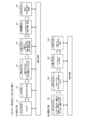
- FIG. 3 is a diagram showing processing steps (working steps) performed at a delivery source constituting the delivery system 1 according to the first embodiment of the present invention.
- the center 10 is a generic term for a product management center (product management source), a delivery center (delivery source), a monitoring center (monitoring source), and the like, as described above.
- FIG. 3 shows each work process included in the “BOX delivery process” and “BOX collection process” performed in the center 10.
- the order receiving process is a process of receiving an order made using an EC site that enables electronic commerce.
- the order receiving process when an order is received, there is a storing process (A2) in which the ordered product is stored (stored) in the delivery box 300 as a package.
- a delivery box 300 suitable for delivery of a package is selected from a plurality of delivery boxes 300 according to the size (size), shape, quantity, impact resistance, etc. of the package, and the selected delivery box 300 is selected. Pack the luggage in and store (store) it.
- the vehicle determination step (A3) for determining the mother vehicle 100 that is the delivery vehicle on which the child vehicle 200 is mounted.
- this vehicle determination step when a delivery vehicle is determined, there is an information setting step (A4) in which predetermined information is set (stored) in each storage device of the delivery box 300, the child carriage 200, and the mother carriage 100.
- the child car identification information (child car ID) for identifying the child car 200 on which the delivery box 300 is loaded and the delivery information specifying the delivery destination 20 are stored.
- box identification information for identifying the delivery box 300 loaded on the child car 200, authentication information, and mother car identification information for identifying the mother car 100 on which the child car 200 is mounted (the mother car) ID) and delivery information specifying the delivery destination 20 are stored at least.
- the child carriage ID for identifying the child carriage 200 mounted on the mother carriage 100, the delivery information designating the delivery destination 20, and the arrangement of the delivery box 300 in the mother carriage 100. Set the box management information for managing.
- a delivery instruction step (A6) in which a “BOX delivery request” is sent to the mother car 100 to give a delivery instruction.
- the carriage 100 can leave from the center 10 toward the delivery destination 20.
- the center 10 receives a “removal completion notification” indicating that the package has been removed from the delivery box 300, and then the center 10 sends a “BOX collection inquiry notification” to a predetermined mother car 100. There is an inquiry process (B1) to send.
- this inquiry step (B1) when the center 10 transmits a “BOX collection inquiry notification” to the predetermined carriage 100, the delivery box 300 is not loaded from the carriage 100 that has received this notification. It indicates that the delivery box 300 can be collected by mounting the child car 200, or that there is no child car 200 on which the delivery box 300 is not loaded and the delivery box 300 cannot be collected.
- a notification receiving step (B2) for receiving a “BOX inquiry response notification”.
- the carriage 100 transmits information necessary for the center 10 to determine the carriage 100 for collecting the delivery box 300, such as the current location and the remaining delivery number, included in the “BOX inquiry response notification”. May be.
- the notification receiving step (B2) when the “BOX inquiry response notification” is received from each of the mother carriages 100, the delivery box 300 is collected based on the “BOX inquiry response notification” received from each of the mother carriages 100. There is a mother wheel determination step (B3) for determining the mother wheel 100 to be performed.
- this mother carriage determination step (B3) the distance, movement route, etc. to the delivery destination 20 where the collection box 300 to be collected is installed among the mother carriages 100 carrying the child carriage 200 not loaded with the delivery box 300 are determined. Considering this, the mother carriage 100 corresponding to the collection of the delivery box 300 is determined.
- the collection route of the delivery box 300 is searched for the delivery route, and the delivery box 300 is collected.
- the center 10 instructs delivery and collection of the delivery box 300.
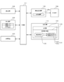
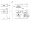
- FIG. 4 is a diagram showing an electrical configuration of the carriage 100 according to the first embodiment of the present invention.
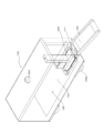
- FIG. 5 is a diagram showing an external configuration of the carriage 100 according to the first embodiment of the present invention.
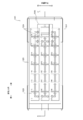
- FIG. 6 is a diagram illustrating an internal configuration of the storage 120 included in the automatic warehouse 110 according to the first embodiment of the present invention, and is a view of the inside of the storage 120 viewed from above.
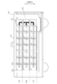
- FIG. 7 is a diagram showing an internal configuration of the storage 120 included in the automatic warehouse 110 according to the first embodiment of the present invention, and shows an A-A when the storage 120 is cut along the line AA ′ shown in FIG. It is A 'arrow view.
- FIG. 4 is a diagram showing an electrical configuration of the carriage 100 according to the first embodiment of the present invention.
- FIG. 5 is a diagram showing an external configuration of the carriage 100 according to the first embodiment of the present invention.
- FIG. 6 is a diagram illustrating an internal configuration of the storage 120 included in the automatic warehouse 110 according to the first embodiment of the present invention
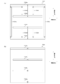
- FIG. 8 is a diagram illustrating the conveyor 131 that constitutes the transport control mechanism 130 included in the automatic warehouse 110 according to the first embodiment of the present invention.
- FIG. 8A shows a first conveyor 132 that is one of the conveyors 131.
- FIG. 8B shows a second conveyor 133 that is one of the conveyors 131.
- the carriage 100 includes a control unit 101, a communication device 102, a detection device 103, a storage device 104, an operation control device 105, a travel mechanism 106, and an automatic warehouse 110.
- the control unit 101 is a control unit that comprehensively controls the entire function of the mother carriage 100 including the automatic driving control mechanism and the delivery control mechanism as described above.
- the control unit 101 may be an ECU (Electronic Control Unit), for example.
- the communication device 102 is a mobile communication device that can perform mutual communication with the center 10 and mutual communication with the child car 200.
- the communication device 102 can also perform mutual communication with other mother carriages 100.
- the detection device 103 recognizes the surroundings of the mother vehicle 100 including a traffic lane defined by other nearby vehicles, pedestrians, animals, fallen objects, grooves, unevenness, center lines, etc., and signals.
- the various radars and various sensors that constitute the detection device 103 are, for example, a laser sensor, an infrared sensor, an ultrasonic sensor, a pyroelectric sensor, and 3D-LiDAR (3D-Light Detection-and-Ranging). These various sensors include a camera.
- the detection device 103 recognizes the situation around the carriage 100 based on information obtained by a camera face recognition system and a human body detection system. As a result, the mother carriage 100 can safely drive (mov) automatically to the relay point 21 or its vicinity while avoiding various dangers on the road.
- the storage device 104 is a storage device that stores various information necessary for executing various control processes performed by the automatic operation control mechanism and the delivery control mechanism as described above.
- the storage device 104 stores various information transmitted and received through mutual communication with the center 10 and the child car 200, and various information for traveling on the delivery route by automatic driving.
- delivery information that is information about the delivery destination 20, map information used to determine a delivery route to the package delivery destination 20, and a travel route (travel route, delivery route) of the carriage 100 Road information, traffic information, and the like related to the road are stored.
- the storage device 104 stores “box management information” for managing the arrangement of the delivery boxes 300 stored in the automatic warehouse 110.
- the operation control device 105 is a control unit that controls the traveling mechanism 106 of the carriage 100.
- the travel mechanism 106 is a vehicle mechanism related to travel of the mother carriage 100.
- the traveling mechanism 106 corresponds to an engine, driving wheels 106a, various actuators, motors (servo motors, in-wheel motors), cylinders, and the like.
- FIG. 5 shows a drive wheel 106a for the carriage 100 to travel on the road as an example of the travel mechanism 106.
- the driving control device 105 performs driving control of the traveling mechanism 106 to perform not only movement (driving) such as driving and stopping of the mother carriage 100 but also parallel parking and turning in a narrow place (alley, etc.). Therefore, it is possible to perform operation control such as parallel movement to the left and right, rotation on the spot, parallel movement in an oblique direction as well as forward and backward movement.
- the operation control device 105 also includes a GPS (Global Positioning System) device 105a capable of specifying (positioning) a position on the map information. Furthermore, the operation control device 105 includes a receiver that can be connected to a VICS (Vehicle Information and Communication System) or a similar road traffic information communication system, and can acquire road information and traffic information provided by the system. is there.
- VICS Vehicle Information and Communication System
- the operation control device 105 uses the information (map information, road information, traffic information, etc.) stored in the storage device 104 and the GPS device 105 a to the delivery destination 20 from the current position (current location).
- the delivery route (movement route) is searched and stored, and the operation (movement) is performed based on this delivery route.
- the operation control device 105 can appropriately update (change) this delivery route based on new traffic information, road information, and the like.
- the automatic warehouse 110 can store one or a plurality of delivery boxes 300 and can change the arrangement of the delivery boxes 300 in the automatic warehouse 110 without depending on the work of the worker. Based on a command from the control unit 101, the automatic warehouse 110 transports the delivery box 300 to a predetermined position (a “receiving / accommodating position” described later) in the automatic warehouse 110. The delivery box 300 transported to this predesignated position is received by the arm of the child car 200 and loaded on the child car 200.
- a predetermined position a “receiving / accommodating position” described later
- the automatic warehouse 110 includes a storage box 120 and a transport control mechanism 130.
- the storage box 120 is a warehouse for storing one or a plurality of delivery boxes 300. As shown in FIG. 5, the storage case 120 forms a casing of the carriage 100. That is, since the carriage 100 is an unmanned automatic driving delivery vehicle that does not require a driver's boarding space, the cabin of the carriage 100 can be formed in the storage 120.
- a door 125 serving as an entrance / exit of the child carriage 200 is provided in the rear side portion of the storage box 120.
- the door 125 functions as a warehousing path and a warehousing path when the child car 200 enters and exits (in / out).
- a mounting space 121 in which the child carriage 200 is mounted and a main space 122 in which the delivery box 300 is stored are provided.
- the mounting space 121 is not only a standby place where the child car 200 waits, but also a work place for loading the delivery box 300 on the child car 200 and preparing for delivery. That is, it can be said that the storage 120 stores the child car 200 in addition to the delivery box 300.
- the main space 122 is provided with a rack (not shown) in which a plurality of delivery boxes 300 can be three-dimensionally stored, and a plurality of storage spaces 123 in which the plurality of delivery boxes 300 are stored are secured. That is, the main space 122 is defined in each of the plurality of storage spaces 123. Each position of the plurality of storage spaces 123 corresponds to a storage position of the delivery box 300.
- the plurality of storage spaces 123 are arranged in a matrix adjacent to each other along the floor surface of the storage 120 that is a substantially uniform plane.
- the plurality of storage spaces 123 are three-dimensionally arranged adjacent to each other along the height direction of the storage case 120 (the vehicle height direction of the mother carriage 100).
- the space near the door 125 is defined as a mounting space 121 in which the child carriage 200 is mounted. That is, the internal space of the storage 120 has a plurality of levels (a plurality of levels) when the plurality of storage spaces 123 and the mounting space 121 arranged along the floor surface of the storage 120 are defined as one level (level). It can be said that it is comprised by laminating
- the space adjacent to the mounting space 121 is a storage in which the child carriage 200 positioned in the mounting space 121 can receive the delivery box 300 arranged in the storage space 123 adjacent to the mounting space 121.
- Space 123 the storage space 123 adjacent to the mounting space 121 among the plurality of storage spaces 123 provided in the storage 120 is referred to as a “reception storage space 124”.
- the position of the receiving and storing space 124 is referred to as a “receiving and storing position”.
- a plurality of receiving storage spaces 124 are provided for each level.
- FIGS. 6 and 7 eight spaces arranged in the front-rear direction of the mother carriage 100 are arranged in the storage box 120 by three rows in the vehicle width direction of the mother carriage 100 per level 24. Spaces are arranged. And, with 24 spaces arranged in a matrix along the floor of the storage 120 as one layer, three layers of “upper”, “middle” and “lower” are arranged. That is, in the example illustrated in FIGS. 6 and 7, 72 spaces are defined in the internal space of the storage case 120. In other words, in the example shown in FIGS. 6 and 7, 72 spaces are provided in the storage case 120.
- (1) to (24) and (A) to (X) are symbols for indicating the positions of a plurality of spaces provided in the storage 120.
- three spaces (16, H), (16, P), and (16, X) correspond to the mounting space 121.
- 69 spaces other than (16, H), (16, P), and (16, X) correspond to the storage space 123.
- (8, H), (8, P) and (8, X) correspond to the 69 storage spaces 123, (8, H), (8, P) and (8, X), (24, H), (24, P) and (24, X), and ( The nine spaces 15, G), (15, O), and (15, W) correspond to the receiving storage space 124.
- some of the plurality of storage spaces 123 are blank (empty space) in advance without storing the delivery box 300 from the stage of the departure preparation step (A5) in FIG. 3 in order to change the arrangement of the delivery box 300. It is in the state. Specifically, in FIG. 6 and FIG. 7, in 69 storage spaces 123, only one storage space 123 is blanked at any level. For example, in the example shown in FIGS. 6 and 7, the storage space 123 (15, G), which is one of the receiving storage spaces 124 in the upper hierarchy, is blanked in advance. For this reason, in the example shown in FIGS. 6 and 7, the storage box 120 can store a maximum of 68 delivery boxes 300. In addition, the hierarchy without the storage space 123 in the blank state is also referred to as the “packed hierarchy” of the delivery box 300.
- the transport control mechanism 130 is a mechanism that controls the change in the arrangement of the delivery box 300 in the automatic warehouse 110. Specifically, the transport control mechanism 130 is a mechanism that performs control to transport the delivery box 300 arranged in the storage space 123 (storage position) in the storage 120 to another storage space 123 in the storage 120. is there.
- the transport control mechanism 130 includes a plurality of conveyors 131 and a transport control unit 135.
- the plurality of conveyors 131 are mechanisms for transporting the delivery box 300 arranged in the storage space 123 (storage position) to another storage space 123 adjacent to the storage space 123.
- each of the plurality of conveyors 131 is configured by a roller conveyor with a pulley, for example.
- each of the plurality of conveyors 131 is provided for each of the plurality of storage spaces 123 in the storage box 120.
- Each of the plurality of conveyors 131 and each of the plurality of storage spaces 123 are associated with each other.
- each of the plurality of conveyors 131 is provided with a sensor capable of detecting the identification information of the delivery box 300 placed on each conveyor 131. Based on the information detected by these sensors, the carriage 100 can acquire the identification information of the delivery box 300 arranged in each of the plurality of storage spaces 123.
- each of the plurality of conveyors 131 is provided with a restraining tool for restraining the delivery box 300 placed on each conveyor 131.
- the carriage 100 can restrain the delivery box 300 from being displaced by restraining the delivery box 300 with these restraints during traveling.
- the plurality of conveyors 131 are composed of at least two types of conveyors.
- one type of conveyor 131 of at least two types is referred to as a “first conveyor 132”
- the other type of conveyor 131 is referred to as a “second conveyor 133”.
- the first conveyor 132 is a conveyor 131 that can transport the delivery box 300 in the front-rear direction and the vehicle width direction of the carriage 100.
- the first conveyor 132 is provided for at least the receiving storage space 124 among the plurality of storage spaces 123.
- 6 and 7 indicate the directions in which each of the first conveyor 132 and the second conveyor 133 conveys the delivery box 300.
- the first conveyor 132 has (8, H), (8, P) and (8, X), and (24, H), (24, P) and (24 , X), and receiving storage spaces 124 located at (15, G), (15, O) and (15, W). Further, the first conveyor 132 includes (7, G), (7, O) and (7, W), (23, G), (23, O) and (23, W), and (1 , A), (1, I) and (1, Q) and (9, A), (9, I) and (9, Q) and (17, A), (17, I) and It is provided for the storage space 123 located at (17, Q).
- the first conveyor 132 includes a motor roller 132a with a pulley and a free roller 132b with a pulley, a motor roller 132c with a pulley, and a free roller 132d with a pulley. Yes.
- the motor roller 132a and the free roller 132b are conveyors for transporting the delivery box 300 in the front-rear direction of the carriage 100.
- the motor roller 132 a and the free roller 132 b are provided such that their longitudinal directions extend in a direction substantially perpendicular to the front-rear direction of the carriage 100.
- the motor roller 132c and the free roller 132d are conveyors for conveying the delivery box 300 in the width direction of the carriage 100.
- the motor roller 132c and the free roller 132d are provided such that their longitudinal directions extend in a direction substantially perpendicular to the vehicle width direction of the carriage 100.
- the motor roller 132a, the free roller 132b, the motor roller 132c, and the free roller 132d are moved up and down in the vehicle height direction of the carriage 100 to bring the contact state with the delivery box 300 into the non-contact state.
- a switching mechanism is provided. For example, when the first conveyor 132 conveys the delivery box 300 in the front-rear direction of the carriage 100, the contact state of the motor roller 132c and free roller 132d with the delivery box 300 is switched to the non-contact state. When the first conveyor 132 conveys the delivery box 300 in the vehicle width direction of the carriage 100, the contact state between the motor roller 132a and the free roller 132b and the delivery box 300 is switched to the non-contact state. Thereby, the 1st conveyor 132 can convey the delivery box 300 to both the front-back direction and the vehicle width direction of the mother carriage 100.
- the second conveyor 133 is a conveyor 131 that can transport the delivery box 300 in the front-rear direction of the carriage 100.
- the second conveyor 133 is provided for the storage spaces 123 other than at least the receiving storage space 124 among the plurality of storage spaces 123.
- the second conveyor 133 has white arrows extending only in the front-rear direction of the mother carriage 100 such as (2, B), (2, J), and (2, R). It is provided for the storage space 123 at the position.
- the 2nd conveyor 133 is comprised from the motor roller 133a with a pulley and the free roller 133b with a pulley, as FIG.8 (b) shows.
- the motor roller 133a and the free roller 133b are conveyors for transporting the delivery box 300 in the front-rear direction of the carriage 100.
- the motor roller 133 a and the free roller 133 b are provided such that their longitudinal directions extend in a direction substantially perpendicular to the front-rear direction of the carriage 100.
- the conveyance control unit 135 is a control unit that controls the plurality of conveyors 131.
- the transfer control unit 135 sets the plurality of conveyors 131 so that the delivery box 300 arranged in the storage space 123 in the storage 120 is transferred to the receiving storage space 124 (reception storage position) in the storage 120. Process to control.
- the conveyance control unit 135 controls at least one of the first conveyor 132 and the second conveyor 133.
- the mother carriage 100 includes a monitoring camera that can monitor the periphery of the mother carriage 100, and also includes a microphone and a speaker at a predetermined part.
- the maintenance monitor of the monitoring center can monitor the surrounding situation with the monitoring camera mounted on the mother car 100 through mutual communication with the center 10 (particularly the monitoring center). In addition to confirming the above, it is possible to have a conversation with the surrounding people, and it is also possible for the maintenance monitor to operate by remote control while confirming the safety of the surrounding situation with a camera or the like.
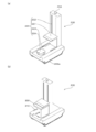
- FIG. 9 is a diagram illustrating an electrical configuration of the child carriage 200 according to the first embodiment of the present invention.
- FIG. 10 is a diagram showing an external configuration of the child carriage 200 according to the first embodiment of the present invention.
- FIG. 10A shows a state where the delivery box 300 is not loaded on the child car 200.
- FIG. 10A shows a state where the delivery box 300 is loaded on the child carriage 200.
- the child carriage 200 includes a control unit 201, a communication device 202, a detection device 203, a storage device 204, an operation control device 205, a travel mechanism 206, and a load control mechanism 210. .
- the control unit 201 is a control unit that comprehensively controls the entire functions of the child carriage 200 including the automatic operation control mechanism and the delivery control mechanism as described above.
- the control unit 201 may be an ECU (Electronic Control Unit), for example.
- the communication device 202 is a mobile communication device that can perform mutual communication with the center 10 and mutual communication with the mother carriage 100.
- the communication device 202 can also perform mutual communication with the delivery box 300 and mutual communication with the recipient of the delivery destination 20. Furthermore, the communication device 202 can also perform mutual communication with another child vehicle 200.
- the detection device 203 recognizes the surroundings of the child vehicle 200 including a surrounding lane, a pedestrian, an animal, a fallen object, a groove, an unevenness, a driving lane defined by a center line, and a signal.
- the various radars and various sensors constituting the detection device 203 are, for example, a laser sensor, an infrared sensor, an ultrasonic sensor, a pyroelectric sensor, a 3D-LiDAR, an electromagnetic wave sensor, and the like. These various sensors include a camera.
- the detection device 203 recognizes the situation around the child car 200 based on information obtained by a face recognition system using a camera and a human body detection system. As a result, the child car 200 can safely and automatically drive (move) to the delivery destination 20 or the vicinity thereof while avoiding various dangers on the road.
- the detection device 203 is also used when checking the position of the hole 410 in the delivery box fixture 400.
- the storage device 204 is a storage device that stores various information necessary for executing various control processes performed by the automatic operation control mechanism and the delivery control mechanism as described above.
- the storage device 204 stores various information transmitted and received through mutual communication with the center 10, the mother carriage 100, and the delivery box 300, and various information for traveling on the delivery route in an automatic operation.
- delivery information that is information related to the delivery destination 20, map information used to determine a delivery route to the delivery destination 20 of the package, and a travel route (travel route, delivery route) of the child car 200 Road information, traffic information, and the like related to the road are stored.
- the operation control device 205 is a control unit that controls the traveling mechanism 206 of the child car 200.
- the travel mechanism 206 is a vehicle mechanism related to the travel of the child car 200.
- the traveling mechanism 206 corresponds to an engine, driving wheels 206a, various actuators, motors (servo motors, in-wheel motors), cylinders, and the like.
- driving wheels 206 a for the child vehicle 200 to travel on the road are shown.
- the drive wheel 206a is configured by a crawler capable of running through a step, rough terrain, and the like.
- the driving control device 205 performs driving control of the traveling mechanism 206 to perform parallel parking and direction change in a narrow place (alley, etc.) as well as movement (driving) of the child car 200 such as driving and stopping. Therefore, it is possible to perform operation control such as parallel movement to the left and right, rotation on the spot, parallel movement in an oblique direction as well as forward and backward movement.
- the operation control device 205 has a balance control function for preventing a fall when the stairs and the like are moved up and down and on a slope.
- This balance control function is a function that detects the position of the center of gravity based on the child carriage 200 and the delivery box 300 one by one and automatically adjusts the position of the center of gravity using the center of gravity position adjusting device 205b (balancer).
- the driving control device 205 controls the balance of the child vehicle 200 by keeping the momentum at the center of gravity position at a constant value using the center of gravity position adjusting device 205b.
- the center-of-gravity position adjusting device 205b can minimize the rollover or fall of the child carriage 200 due to collision or contact with an obstacle.
- the operation control device 205 also includes a GPS device 205a capable of specifying (positioning) a position on the map information. Further, the operation control device 205 includes a receiver that can be connected to a VICS or similar road traffic information communication system, and can acquire road information and traffic information provided by this system.
- the child car 200 uses the information (map information, road information, traffic information, etc.) stored in the storage device 204 and the GPS device 205a by the operation control device 205 to the delivery destination 20 from the current position (current location).
- the delivery route (movement route) is searched and stored, and the operation (movement) is performed based on this delivery route.
- the operation control device 205 can appropriately update (change) this delivery route based on new traffic information, road information, and the like.
- the loading control mechanism 210 is a mechanism for controlling the loading of the delivery box 300 delivered to the delivery destination 20 on the child car 200 based on a command from the control unit 201. Specifically, the loading control mechanism 210 performs control to receive the delivery box 300 that is transported and controlled by the transport control mechanism 130 of the automatic warehouse 110 into the receiving storage space 124 in the storage 120 and to load the delivery box 300 on the slave car 200. Mechanism. The child car 200 delivers the delivery box 300 loaded on the child car 200 by being loaded by the loading control mechanism 210 to the delivery destination 20 as the delivery box 300 delivered to the delivery destination 20. .
- the loading control mechanism 210 includes a loading mechanism 220 and a loading control unit 230. As illustrated in FIG. 10A, the loading mechanism 220 includes an arm 221 (holding unit), an elevating unit 222, a translation unit 223, and a loading platform 224.
- the arm 221 is a means for realizing the delivery control mechanism of the child car 200 as described above, and holds the delivery box 300 loaded on the child car 200 at the time of delivery as shown in FIG. Fix to the fixture 400.
- the arm 221 receives the delivery box 300 arranged in the receiving storage space 124 in the storage 120 and places it on the loading platform 224 when the child carriage 200 is mounted in the mounting space 121 in the storage 120. be able to.
- the arm 221 can hold the delivery box 300 placed on the loading platform 224.
- the child carriage 200 is in a state in which the delivery box 300 is loaded. That is, the state in which the delivery box 300 is loaded on the child carriage 200 may be a state in which the delivery box 300 placed on the loading platform 224 is held by the arm 221.
- the elevating unit 222 is a mechanism that elevates and lowers the arm 221 in the height direction of the child carriage 200.
- the arm 221 and the elevating part 222 function as a lifter for the child carriage 200.
- the translation unit 223 is a mechanism that translates the arm 221 in the front-rear direction of the child carriage 200.
- the loading platform 224 is configured by a flat pedestal so that the bottom surface of the delivery box 300 is attached. Furthermore, the loading platform 224 includes a mechanism for rotating the placed delivery box 300, and is configured so that the orientation of the delivery box 300 can be changed.
- the loading control unit 230 is a control unit that controls the loading mechanism 220. For example, when the loading control unit 230 receives the delivery box 300 arranged in the receiving storage space 124 in the storage 120 by the loading mechanism 220 and loads it on the child carriage 200, the loading control unit 230 replaces each component of the loading mechanism 220 with the following. So as to drive in conjunction.
- the loading control unit 230 drives the lift unit 222 and the translation unit 223 to move the arm 221 to the receiving storage space 124. Then, the stacking control unit 230 drives the arm 221 moved to the receiving / accommodating space 124 to hold the delivery box 300 disposed in the receiving / accommodating space 124 on the arm 221. Then, the stacking control unit 230 drives the lifting unit 222 and the translation unit 223 to move the arm 221 holding the delivery box 300 to the loading platform 224, and places the delivery box 300 on the loading platform 224.
- the loading control unit 230 drives each component of the loading mechanism 220 so that the delivery box 300 arranged in the storage space 123 of a specific level in the storage 120 is transferred to another level different from the specific level. Can be controlled.
- the control process for transferring the delivery box 300 between the tiers of the storage 120 is referred to as “inter-tier transfer control process”.
- the function of executing the inter-tier transfer control process is referred to as an “inter-tier transfer control unit 231”.
- the loading control unit 230 holds, for example, the delivery box 300 arranged in the receiving storage space 124 located at (15, W) in the lower level with the arm 221, and It can be transferred to a blank receiving storage space 124 located at (15, G) of the level.
- the child car 200 includes a monitoring camera capable of monitoring the surroundings of the child car 200, and also includes a microphone and a speaker at a predetermined part.
- a maintenance monitor of the monitoring center uses a monitoring camera mounted on the child car 200 to communicate with the center 10 (particularly, the monitoring center). In addition to confirming the above, it is possible to have a conversation with the surrounding people, and it is also possible for the maintenance monitor to operate by remote control while confirming the safety of the surrounding situation with a camera or the like.
- the child car 200 can stop the travel of the child car 200 by pressing (or touching) the emergency stop button when the surrounding person feels danger. It is possible to check the surrounding situation with a monitoring camera mounted on the child car 200 and talk with the surrounding people.
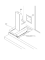
- [5. Delivery mode of delivery system] 11 to 14 are diagrams showing a delivery mode in the delivery system 1 according to the first embodiment of the present invention.
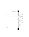
- FIG. 11 shows a roadway, a sidewalk provided along the roadway, a delivery destination passage substantially perpendicular to the sidewalk, and a step provided between the delivery destination passage and the delivery box fixture 400 of the delivery destination 20. (Staircase) is shown. Further, FIG. 11 shows a space where the arm 221 can be moved in order to install the delivery box 300 on the delivery box fixture 400 beyond the step, and a delivery destination designated for each delivery destination 20. The specified space is shown. Further, FIG. 11 shows a delivery box fixture 400 provided on the wall surface of the delivery destination 20.
- the carriage 100 is in a state of stopping at the end of the roadway as the relay point 21 (for example, “relay point 1”) corresponding to the delivery destination 20.
- the child carriage 200 that gets off from the carriage 100 at the relay point 21 leaves the door 125 of the carriage 100 as a delivery path and then moves along the sidewalk along the delivery path.
- the position of the hole 410 of the delivery box fixture 400 is confirmed, and then the delivery box 300 is moved to the hole 410. To fix.
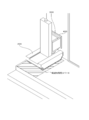
- FIGS. 12 to 14 are diagrams showing how the delivery box 300 is fixed to the delivery box fixture 400 by the movement of the arm 221 of the child carriage 200 in the delivery destination designation space provided in the delivery destination 20. .
- This delivery destination designation space is a work area that is provided in the front position of the delivery box fixture 400 and consists of a certain range in which the delivery box 300 is fixed by moving the arm 221 of the child carriage 200.
- the child car 200 When the child car 200 belongs to this delivery destination designation space (see FIG. 12), the child car 200 confirms the position of the hole 410 provided in the delivery box fixture 400 (position recognition).
- the child carriage 200 lifts the delivery box 300 from the carrier 224 and moves it forward of the child carriage 200 by the movement control of the arm 221.
- the child carriage 200 hooks the delivery box 300 by inserting (penetrating) the protruding portion 310 of the delivery box 300 into the hole 410 whose position is recognized.
- the delivery box fixture 400 shown in FIGS. 12 to 14 has four holes 410 (first hole 410a, second hole 410b, third hole 410c, and fourth hole 410d).
- the delivery box 300 has four protrusions 310 (first protrusion 310a, second protrusion 310b, third protrusion 310c, and fourth protrusion 310d) that are provided and inserted into the holes 410, respectively. is doing.
- the delivery box fixture 400 may have a plurality of holes 410, whereas the delivery box 300 may have only a single protrusion, or vice versa.
- the protrusion 310 is a mechanism that can be embedded in the delivery box 300 with a spring or the like (a mechanism that can be recessed)
- the quantity of the “hole 410” is “the quantity of the protrusion 310”. Or less.
- the number of engaging portions (projections 310 and holes 410) between the delivery box fixture 400 and the delivery box 300 is not necessarily the same.
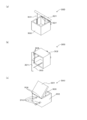
- FIG. 15 is a diagram showing a detailed configuration of the delivery box 300 according to the first embodiment of the present invention.
- the delivery box 300 includes a lid portion 301, a luggage storage portion 302, a damper 303, and a hinge 304.
- the lid portion 301 and the luggage storage portion 302 are joined by a hinge 304.
- the delivery box 300 uses the hinge 304 as a fulcrum, the lid portion 301 is opened, and the damper 303 can be kept open and closed slowly.
- FIG. 15A shows a state in which the lid portion 301 can be opened and closed in the vertical direction
- FIG. 15B shows a state in which the lid portion 301 can be opened and closed in the front direction.
- These delivery boxes 300 are appropriately selected depending on the package to be delivered.
- FIG. 15 (c) is a view showing the back surface provided with the protrusion 310 by rotating FIG. 15 (a).
- This protrusion 310 is provided in a positional relationship corresponding to a hole 410 provided in a delivery box fixture 400 described later.
- the protrusion 310 can also be referred to as a portion (first engagement portion) that engages with the hole 410 provided in the delivery box fixture 400.
- FIG. 16 is a diagram showing a detailed configuration of the delivery box fixture 400 according to the first embodiment of the present invention.
- the delivery box fixture 400 shown in FIG. 16 is provided with four holes (a first hole 410a, a second hole 410b, a third hole 410c, and a fourth hole 410d). It is a site
- the hole 410 can also be referred to as a portion (second engagement portion) that engages with the protrusion 310 provided in the delivery box 300.
- the hole portion 410 is configured by combining two circular portions, an upper circular portion and a lower circular portion, respectively.
- a protrusion 310 provided in the delivery box 300 is fitted (engaged) with the two circular portions of the upper circular portion and the lower circular portion. Note that the cylindrical portion of the protrusion 310 protrudes from the delivery box 300 and is provided to prevent the delivery box 300 from being lifted upward.
- FIG. 17 is a diagram illustrating an engagement state between the delivery box 300 and the delivery box fixture 400 according to the first embodiment of the present invention.
- FIG. 17 shows a state in which the protrusion 310 of the delivery box 300 is inserted into (latched into) the hole 410 of the delivery box fixture 400 and is fixed (engaged).
- a large hole (first hole shape) and a small hole (second hole shape) are combined with each other to form one hole.
- the projection 310 of the delivery box 300 After inserting the projection 310 of the delivery box 300 into this large hole, the projection 310 is moved to a small hole, and the delivery box 300 is engaged with the delivery box fixture 400 and fixed.
- FIG. 18 is a diagram showing the contents of mail received by the recipient of the package.
- This mail has header information including a destination (TO: xxx@yyy.jp), a delivery source (FROM: (delivery person or package sender)), a title (SUBJECT: notification of delivery completion), etc.
- the message content, delivery box identification information (BOX number) for identifying the delivery box, and unlock key code are included.
- the recipient of the package By receiving such mail contents, the recipient of the package recognizes that the package has been delivered, identifies the delivery box 300, unlocks the identified delivery box 300, and takes out the package. It becomes possible.
- FIG. 19 is a flowchart showing a detailed flow of the BOX delivery control process performed in the carriage 100 according to the first embodiment of the present invention.
- the carriage 100 (control unit 101) confirms “delivery information” and “collection information” which are information received or set by communication with the center 10 (S1901).
- This delivery information includes information including the address and name of the delivery destination 20, a “fixing tool number” for identifying the delivery box fixture 400, and “box identification information” for identifying the delivery box 300 to be delivered. It is.
- the collection information includes information including a collection destination address and name, “fixing device number” for identifying the delivery box fixture 400, “box identification information” for identifying the delivery box 300 to be collected, and the like. It is.
- the mother carriage 100 searches for a delivery route to the delivery destination 20 based on map information and traffic information stored in advance (S1902), and sets (stores). (S1903).
- the carriage 100 determines whether or not a delivery start condition that is a condition for starting delivery from the current location (for example, the center 10) is satisfied (S1904).
- the delivery start condition is that the carriage 100 is in a departure order starting from the center 10 or a set departure time.
- Stroller 100 (control unit 101) continues the standby state until it is determined that the delivery start condition is satisfied (NO in S1904).
- This operation control process is a process of moving the delivery route from the current position (current location) to the delivery destination 20 using each piece of information (map information, road information, traffic information, etc.) and the GPS device 105a.
- the mother car 100 Based on the information obtained by the detection device 103, the mother car 100 is aware of the driving lanes, signals, and the like defined by surrounding other vehicles, pedestrians, animals, falling objects, grooves, unevenness, centerlines, etc. It moves (runs) on the delivery route by automatic driving.
- the carriage 100 (the control unit 101) performs an automatic warehouse control process (S1906).
- the delivery box 300 delivered to the delivery destination 20 is arranged in the receiving storage space 124 in the storage 120 before the child car 200 is dismounted at the relay point 21 on the delivery route.
- This is a process for controlling the transport control mechanism 130 of the automatic warehouse 110.
- the child car 200 can receive and load the delivery box 300 arranged in the receiving storage space 124 before it gets off from the child car 200 at the relay point 21.
- the mother carriage 100 determines whether or not it has arrived at the relay point 21 for the delivery destination 20 indicated by the “delivery information” on the delivery route or in the vicinity thereof (S1906).
- the main carriage 100 (the control unit 101) continues the driving control process and the automatic warehouse control process until it arrives at these points (the relay point 21 or the vicinity thereof) by the driving control process (NO in S1907).
- the mother carriage 100 determines whether or not the child carriage 200 has been issued from the mother carriage 100 by this delivery control process (S1909), and until the child carriage 200 completes the delivery from the mother carriage 100 ( In step S1909, NO) performs a delivery control process (S1909).
- the mother carriage 100 (control unit 101) continuously performs the communication control process with the delivered child carriage 200.
- the mother carriage 100 and the child carriage 200 can grasp each other's current location and delivery status one by one.
- the mother car 100 determines whether or not the child car 200 has completed delivery and has belonged to a predetermined position (S1911).
- the mother car 100 (the control unit 101) is configured so that the child car 200 fixes the delivery box 300 to the delivery destination 20 and completes the delivery, and then the predetermined position related to the mother car 100 (the mother car 100 for receiving). It is determined whether or not it has returned to the position designated in the relationship.
- the mother car 100 (control unit 101) continues to manage the status of the child car 200 by performing communication control processing with the child car 200 (S1910). .
- the communication control processing performed between the mother carriage 100 and the child carriage 200 includes direct communication performed directly between the mother carriage 100 and the child carriage 200, and the mother carriage 100 and the child carriage 200 via the center 10. May be control processing of indirect communication performed indirectly. Moreover, all the control processes performed in the mother carriage 100 and the child carriage 200 may be based on a communication control instruction from the center 10.
- the mother carriage 100 controls the mother carriage 100 (control unit 101) performs a control process for moving the child carriage 200 into the mother carriage 100 (S1912).
- This warehousing control process is a control process in which the door 125 of the carriage 100 is opened, the door 125 serves as a warehousing path, and the child carriage 200 is admitted to stop at a predetermined stop position in the carriage 100.
- the mother carriage 100 updates the management information (child carriage management information) of the child carriage 200 (S1913). Transmit (S1914).
- the center 10 can grasp that the child car 200 has returned to the mother car 100 normally.
- the communication control process performed between the mother carriage 100 and the child carriage 200 is not only direct communication between the mother carriage 100 and the child carriage 200 but also the mother carriage via the center 10.
- the control process of indirect communication which 100 and the sub-car 200 indirectly perform may be sufficient.
- all the control processes performed in the mother carriage 100 and the child carriage 200 may be based on a communication control instruction from the center 10.
- the carriage 100 determines whether or not the delivery control in the delivery route is managed (S1915), and when it is determined that the delivery of all the delivery boxes 300 is completed (YES in S1915). This process is terminated.
- the carriage 100 performs the operation control process in the delivery of the delivery boxes 300 in the set delivery route. (S1905).
- FIG. 20 is a flowchart showing a detailed flow of the BOX delivery control process performed in the slave vehicle 100 according to the first embodiment of the present invention.
- the child car 200 (the control unit 201) confirms “delivery information” and “collection information” that are information received or set by communication with the center 10 (S2001).
- the delivery information includes the address and name of the delivery destination 20 as well as the “fixing tool number” for identifying the delivery box fixture 400 and the delivery box to be delivered, as with the “delivery information” set in the carriage 100.
- This information includes “box identification information” for identifying 300.
- the collection information includes a collection destination address and name, a “fixing tool number” for identifying the delivery box fixing tool 400, and a collection box to be collected, as with the “collection information” set in the carriage 100.
- This information includes “box identification information” for identifying 300.
- the child car 200 searches for a delivery route to the delivery destination 20 based on map information and traffic information stored in advance (S2002), and sets (stores) it. (S2003).
- the child vehicle 200 determines whether or not a child vehicle delivery start condition that is a condition for starting delivery from the current location (for example, the relay point 21) is satisfied (S2004). .
- the delivery start condition for the child carriage is a condition in which the child carriage 200 can be delivered in consideration of the surrounding road conditions and the like when the door 125 of the carriage 100 is opened.
- the control unit 201 determines that the delivery start condition for the child car is satisfied (NO in S2004), it continues the standby state until it is determined that the delivery start condition is satisfied.
- the child car 200 when determining that the delivery start condition is satisfied (YES in S2004), the child car 200 (the control unit 201) performs an operation control process related to delivery to the delivery destination 20 based on the set delivery route. Perform (S2005).
- the child car 200 determines whether or not it has arrived at the delivery destination 20 indicated by the “delivery information” on the delivery route by this operation control process (S2006).
- the child car 200 (the control unit 201) continues the operation control process until it arrives at the delivery destination 20 by this operation control process (NO in S2006).
- control unit 201 when the child car 200 (control unit 201) arrives at the delivery destination 20 indicated by "delivery information" (YES in S2006), the loaded delivery box 300 is fixed to the delivery box provided in the delivery destination 20.
- a control process (BOX fixing control process) for hooking and fixing the tool 400 is performed (S2007).
- the child carriage 200 (control unit 201) transmits an “attachment completion notice” to the mother carriage 100 and the center 10 (S2008). ).
- the child carriage 200 acquires “position information of the mother carriage” through communication with the mother carriage 100 (S2009), and the mother carriage 100 is obtained based on the obtained “position information of the mother carriage”.
- the “return route” up to is searched (S2010) and set (stored) (S2011).
- the child car 200 determines whether or not a “return start condition” for starting operation control based on the set “return route” is satisfied (S2012).
- the child car 200 determines whether or not all delivery based on the “delivery route” in the set child car 200 is completed (S2014). By this determination process, until all the delivery is completed (NO in S2014), the child car 200 (the control unit 201) continues to perform the operation control based on the “return route” (S2013).
- FIG. 21 is a flowchart showing a detailed flow of the lock control process performed in the delivery box 300 according to the first embodiment of the present invention.
- the delivery box 300 receives an input of “predetermined information” by an information input unit provided in the delivery box 300 by an operation by a recipient of the stored package (S2101).
- the information input unit is provided in the delivery box 300, and as described above, is a touch panel, a button, a camera (imaging device), and the like.
- the delivery box 300 transmits an authentication request including “predetermined information” input from the information input unit to the child car 200 (S2102).
- the control unit 201 receives the authentication request including the “predetermined information” from the delivery box 300, the “predetermined information” is the normal “unlocked” for unlocking the delivery box 300. It is determined whether or not it is “unlock key code”.
- This authentication request includes information for identifying the delivery box 300 in addition to “predetermined information”.
- the child car 200 determines whether or not the “predetermined information” is an “unlock key code” corresponding to the “authentication information” specified for the information for identifying the delivery box 300. Determine and respond to the delivery box 300. That is, in the storage device 204 of the child car 200, “authentication information” corresponding to information for identifying the delivery box 300 is stored, and is “unlocking key code” corresponding to the “authentication information”? A determination program for determining whether or not is stored.
- the delivery box 300 determines whether or not the response from the child car 200 is an authenticated “unlock key code” (S2103).
- the delivery box 300 opens the locked BOX door. Is performed (S2104).
- the delivery box 300 determines whether or not it has been detected that the package has been taken out by the recipient and the BOX door has been closed (S2105).
- the delivery box 300 When the delivery box 300 detects that the BOX door is closed by a sensor or the like (YES in S2105), the delivery box 300 performs a locking process for locking the BOX door (S2106).
- This locking process is a process for preventing the recipient from unlocking the BOX door without entering the “unlocking key code”. If the recipient again inputs the normal “unlocking key code”. This is a process for enabling the opening.
- the delivery box 300 determines whether or not it has been detected by the recipient that the package has been taken out by a sensor (package sensor) provided in the delivery box 300. (S2107).
- the delivery box 300 can accept input of “predetermined information” at the information input unit until it is detected that the package has been removed by the recipient (NO in S2107), that is, when the package has not been removed. To do.
- the delivery box 300 When the delivery box 300 detects that the package has been removed by the recipient (YES in S2107), the delivery box 300 indicates to the center 10 that the package has been removed. ) "Is transmitted (S2108), and this process ends.
- the delivery box 300 determines whether or not the package is taken out by the recipient after the locking process is performed, but the present invention is not limited to this. In other words, the delivery box 300 detects that the package has been taken out by the recipient with the BOX door open, and detects the package with respect to the center 10 by performing the locking process. A “takeout completion notification (including BOX identification information)” indicating that the takeout has been performed may be transmitted.
- FIG. 22 is a flowchart showing a detailed flow of the operation control process performed in the mother carriage 100 according to the first embodiment of the present invention.
- the carriage 100 (the control unit 101) confirms road information, traffic information, and the like of the delivery route as needed using the operation control device 105 and the detection device 103 while moving (running) the delivery route to the delivery destination 20. (S2201).
- the mother carriage 100 determines whether or not to change the delivery destination 20 to be delivered this time (S2202).
- the mother carriage 100 and the child carriage 200 deliver the delivery box 300 to the delivery destination 20 according to a preset delivery order included in the delivery information. At this time, unexpected situations such as traffic jams and traffic closures occur on the delivery route, and delivering the delivery box 300 according to a preset delivery order may be inefficient delivery.
- the carriage 100 determines that the delivery destination 20 is more efficiently delivered as a result of checking the road information and the traffic information, the delivery destination 20 to be delivered this time is determined. Is changed to another delivery destination 20 included in the delivery information (YES in S2202).
- the carriage 100 proceeds to S2208 in order to deliver to a preset delivery destination 20.
- the carriage 100 changes the delivery order information included in the delivery information according to the changed delivery destination 20. Then, the carriage 100 (control unit 101) updates the “delivery information” so that the changed delivery order information is included (S2203), and records that the delivery destination 20 is changed in the “delivery information”. (S2204). Then, the mother carriage 100 (control unit 101) transmits the updated delivery information to the center 10 and the child carriage 200, respectively.
- the carriage 100 searches for a delivery route to the changed delivery destination 20 (S2205), and determines whether or not to change the relay point 21 corresponding to the changed delivery destination 20. (S2206).
- the carriage 100 determines that changing the relay point 21 in accordance with the change of the delivery destination 20 enables more efficient delivery (YES in S2206)
- the relay point 21 Is set as a delivery route (S2207). Then, the mother carriage 100 (the control unit 101) transmits information on the changed relay point 21 to the center 10 and the child carriage 200, respectively.
- the carriage 100 (the control unit 101) delivers from the preset relay point 21.
- the process proceeds to S2208 to perform the above.
- the mother carriage 100 (control unit 101) performs a travel control process related to delivery based on the set delivery route (S2208). Thereafter, the carriage 100 (control unit 101) proceeds to S1906 in FIG.
- FIG. 23 is a flowchart showing a detailed flow of the automatic warehouse control process performed in the carriage 100 according to the first embodiment of the present invention.
- the mother carriage 100 (control unit 101) confirms the stored delivery information and determines whether or not it is recorded that the delivery destination 20 has been changed (S2301).
- the carriage 100 checks the stored “box management information” (S2302).
- the carriage 100 (the control unit 101) does not record that the delivery destination 20 has been changed in the delivery information (NO in S2301), for example, the information is set in advance in the information setting step (A4) in FIG. Based on the “box management information”, the process proceeds to S2305 in order to perform the transport control process for the delivery box 300.
- the box management information is information for managing the arrangement of the delivery boxes 300 stored in the storage 120 of the automatic warehouse 110.
- the box management information includes position information of each space (storage space 123 and mounting space 121) provided in the storage box 120, box identification information of the delivery box 300 arranged in these spaces, and these delivery boxes.
- the transport order information indicating the order of transporting 300 to the receiving storage space 124 is recorded in association with each other.
- the carriage 100 (the control unit 101) needs to change the arrangement of the delivery box 300 in the storage 120 according to the change of the delivery destination 20 based on the delivery information and the box management information. Is determined (S2303).
- the carriage 100 changes the delivery order information included in the box management information to the delivery information. In order to reflect the included delivery order information, the process proceeds to S2304.
- the carriage 100 updates the box management information including the conveyance order information so that the delivery box 300 is conveyed to the receiving storage space 124 according to the changed delivery order (S2304).
- the carriage 100 performs a box conveyance control process (S2305). Specifically, the control unit 101 of the carriage 100 transmits a command for instructing execution of the box conveyance control process to the conveyance control unit 135. This command includes delivery information and box management information.
- the transport control unit 135 executes box transport control processing based on a command from the control unit 101. After the box transport control process is executed by the transport control unit 135, the control unit 101 proceeds to S1907 in FIG.
- control is performed to transport the delivery box 300 delivered to the delivery destination 20 to the receiving storage space 124 based on the delivery information and the box management information, and the delivery box 300 is loaded on the child car 200.
- This is a process for performing control.
- the delivery box 300 to be delivered to the delivery destination 20 is loaded, and preparations for leaving the delivery box 300 are completed.
- FIG. 24 is a flowchart showing a detailed flow of the box transport control process performed in the mother carriage 100 and the child carriage 200 according to the first embodiment of the present invention.
- the mother carriage 100 (the conveyance control unit 135) transmits a notification indicating that the execution of the box conveyance control process is started to the child car 200 (S2401).
- the child car 200 (loading control unit 230) activates the loading mechanism 220 and executes necessary initial settings (S2402).
- the carriage 100 (the conveyance control unit 135) confirms the delivery information and the box management information (S2403). Then, the carriage 100 (the conveyance control unit 135) specifies the delivery destination 20 and the delivery box 300 delivered to the delivery destination 20 using the delivery information (S2404).
- the carriage 100 uses the box management information, for example, positional information on the space (the storage space 123 and the mounting space 121) in the storage box 120 in which the specified delivery box 300 is disposed. Is identified. Then, the carriage 100 (the conveyance control unit 135) searches the storage box 120 for the specified delivery box 300 (S2405), and the specified delivery box 300 is stored in the storage box 120 indicated by the specified position information. Make sure that it is actually placed in the space.
- box management information for example, positional information on the space (the storage space 123 and the mounting space 121) in the storage box 120 in which the specified delivery box 300 is disposed. Is identified. Then, the carriage 100 (the conveyance control unit 135) searches the storage box 120 for the specified delivery box 300 (S2405), and the specified delivery box 300 is stored in the storage box 120 indicated by the specified position information. Make sure that it is actually placed in the space.
- the carriage 100 determines whether or not the identified delivery box 300 is disposed in the receiving storage space 124 (S2406).
- the mother carriage 100 proceeds to S2413 to notify the child car 200 to that effect.
- the carriage 100 determines whether or not the delivery box 300 is stored in a full hierarchy. Is determined (S2407).
- the delivery box 300 When the delivery box 300 is stored in a full hierarchy, when any of the delivery boxes 300 stored in the full hierarchy is transferred to another hierarchy, the delivery box 300 is included in the full hierarchy.
- the arrangement of 300 can be changed. In other words, when the delivery box 300 is stored in a non-full tier with a blank storage space 123, the arrangement of the delivery boxes 300 can be changed in this non-full tier, so that inter-tier transfer control is performed. Processing need not be executed.
- the mother carriage 100 (the conveyance control unit 135) notifies the child car that the inter-tier transfer control process is not executed. 200 (S2408), and the process proceeds to S2412.
- the mother carriage 100 sends a notification indicating that the inter-tier transfer control process is executed. 200 (S2409), and the inter-tier transfer control process is executed (S2411).
- the child car 200 determines whether or not the inter-tier transfer control process is executed in response to a notification from the mother carriage 100 regarding whether or not the inter-tier transfer control process is executed (S2410). Specifically, when the child car 200 receives a notification indicating that the inter-tier transfer control process is to be executed (YES in S2410), the sub car 200 (loading control unit 230) executes the inter-tier transfer control process. (S2411). On the other hand, when a notification indicating that the inter-tier transfer control process is not executed is received by the child car 200 (NO in S2410), the child car 200 (loading control unit 230) is provided with the specified delivery box 300. The process waits until information indicating the position of the receiving storage space 124 and the position of the hierarchy where the receiving storage space 124 is located is transmitted from the mother carriage 100, and the process proceeds to S2414.
- This inter-tier transfer control process is a control process for transferring the delivery box 300 between the tiers of the storage box 120.
- the child carriage 200 (loading control unit 230) transfers the delivery boxes 300 arranged in the full-tiered receiving and storing spaces 124 to the non-full-tiered receiving and storing spaces 124 ( Transfer processing to the receiving storage space 124) of the transfer destination is performed.
- the carriage 100 (the conveyance control unit 135) changes the arrangement of the delivery boxes 300 in the hierarchy where the transfer destination receiving / accommodating space 124 is located so that the transfer destination receiving / accommodating space 124 is in a blank state. I do. That is, in the delivery system 1, even if a stacker crane or the like is not provided in the storage case 120, the child carriage 200 that delivers the delivery box 300 cooperates with the mother carriage 100 to deliver between the respective levels of the storage case 120. Box 300 can be transported.
- the carriage 100 controls the conveyor 131 so that the identified delivery box 300 is conveyed to the receiving storage space 124 in the same hierarchy (S2412).
- the mother carriage 100 sends information indicating the position of the receiving storage space 124 in which the specified delivery box 300 is arranged and the position of the hierarchy in which the receiving storage space 124 is present to the child carriage 200. Transmit (S2413).
- the child car 200 determines whether or not to raise or lower the arm 221 of the loading mechanism 220 based on the notification indicating the position and level of the receiving storage space 124 in which the specified delivery box 300 is arranged. Judgment is made (S2414).
- the child carriage 200 (loading control unit 230) prepares the arm 221 for receiving the delivery box 300 from the mother carriage 100. Then, the child car 200 (loading control unit 230) transmits a notification indicating that it is in a standby state for receiving the delivery box 300 to the mother car 100 (S2416).
- the child carriage 200 drives the lifting unit 222 to receive and store the storage space 124 in which the specified delivery box 300 is arranged.
- the arm 221 is moved up and down to the next level (S2415).
- the child carriage 200 (loading control unit 230) prepares the arm 221 and transmits a notification indicating that it is in a reception standby state to the mother carriage 100 (S2416).
- the mother car 100 When the mother car 100 receives a notification indicating that it is in the reception standby state, the mother car 100 (the conveyance control unit 135) has the delivery box 300 arranged in the receiving storage space 124 by the conveyance in S2412, and the arm 221.
- the conveyor 131 is controlled so as to be conveyed (S2417).
- the child carriage 200 (loading control unit 230) drives the arm 221 to hold the delivery box 300 arranged in the receiving storage space 124 by the arm 221. As a result, the child car 200 can receive the delivery box 300 (S2418).
- the child carriage 200 (loading control unit 230) drives the lifting unit 222 and the translation unit 223 to move the arm 221 holding the delivery box 300 to the loading platform 224, and places the delivery box 300 on the loading platform 224. .
- the child carriage 200 (loading control unit 230) holds the placed delivery box 300 with the arm 221. Accordingly, the child carriage 200 is in a state where the delivery box 300 is loaded.
- the child car 200 (loading control unit 230) sends a notification indicating that the identified delivery box 300, that is, the delivery box 300 delivered to the delivery destination 20, is loaded on the child car 200. This is transmitted to the mother carriage 100 (S2419), and this process is terminated.
- the transport control unit 135 When a notification indicating that the delivery box 300 is in the loaded state is received by the mother carriage 100, the transport control unit 135 confirms that the loading of the delivery box 300 delivered to the delivery destination 20 on the child car 200 is completed. A notification (loading completion notification) is transmitted to the control unit 101 of the carriage 100 (S2420). Then, the transfer control unit 135 updates the box management information so that the arrangement of the delivery box 300 in the storage box 120 is reflected in the box management information, and ends this processing. Upon receiving the loading completion notification, the control unit 101 proceeds to S1907 in FIG.
- FIG. 25 is a flowchart showing a detailed flow of the inter-tier transfer control process performed in the mother carriage 100 and the child carriage 200 according to the first embodiment of the present invention.
- the mother carriage 100 selects the delivery box 300 to be transferred to another level that is not full, among the delivery boxes 300 arranged in the receiving storage space 124 in the full level (S2501).
- the carriage 100 includes the position of the receiving storage space 124 where the selected delivery box 300 is arranged, the position of the hierarchy where the receiving storage space 124 is located, and the selected delivery box 300.
- Information indicating the position of the receiving storage space 124 of the transfer destination and the position of the hierarchy where the receiving storage space 124 of the transfer destination is located is transmitted to the child car 200 (S2502).
- the child car 200 drives the lifting / lowering part 222 to reach the level of the receiving storage space 124 in which the selected delivery box 300 is arranged. Is raised and lowered (S2503). Then, the child carriage 200 (loading control unit 230) prepares the arm 221 for receiving the delivery box 300 from the mother carriage 100, and transmits a notification indicating that it is in a reception standby state to the mother carriage 100 (S2504). .
- the delivery box 300 While the child carriage 200 is driving the arm 221 (S2503 and S2504), if the delivery box 300 is disposed in the receiving storage space 124 of the carriage 100 (the transport control unit 135) (in S2505). YES), the conveyor 131 is controlled so that the receiving and storing space 124 is in a blank state (S2506). On the other hand, if the delivery box 300 is not arranged in the receiving storage space 124 of the transfer destination (NO in S2505), the mother car 100 (the conveyance control unit 135) sends a notification indicating that it is in a reception standby state from the child car 200. The process waits until it is transmitted, and proceeds to S2507.
- the carriage 100 controls the conveyor 131 so that the selected delivery box 300 is conveyed to the arm 221. (S2507).
- the child car 200 (loading control unit 230) drives the arm 221 to hold the selected delivery box 300 by the arm 221. As a result, the child car 200 can receive the delivery box 300 (S2508).
- the child carriage 200 (loading control unit 230) drives the elevating unit 222 to elevate the arm 221 holding the delivery box 300 to the level where the receiving storage space 124 of the transfer destination is located (S2509). Then, the child carriage 200 (loading control unit 230) drives the arm 221 to place the delivery box 300 held by the arm 221 in the receiving storage space 124 of the transfer destination (S2510). As a result, the selected delivery box 300 is transferred to the receiving storage space 124 of the transfer destination.
- the child car 200 (loading control unit 230) transmits a notification indicating that the selected delivery box 300 has been placed in the receiving storage space 124 of the transfer destination to the mother car 100 (S2511), and ends this process.
- the transport control unit 135 confirms that (S2512). Then, the carriage 100 (the conveyance control unit 135) updates the box management information so that the arrangement of the delivery boxes 300 in the storage 120 is reflected in the box management information. Then, the carriage 100 (the conveyance control unit 135) ends this processing, and proceeds to S2412 in FIG.
- FIG. 26 is a diagram schematically illustrating a state in which the arrangement of the delivery box 300 in the storage 120 according to the first embodiment of the present invention is changed, and illustrates a case where the inter-tier transfer control process is not executed.
- FIG. 26 the positions of a plurality of spaces (storage space 123 and mounting space 121) provided in the storage 120 are specified using the same notation as in the examples shown in FIGS.
- a gray delivery box 300 in FIG. 26 indicates the delivery box 300 delivered to the delivery destination 20.
- the broken line of FIG. 26 has shown the storage space 123 of the blank state.
- FIG. 26A shows the arrangement of the delivery box 300 before the change.
- the delivery box 300 delivered to the delivery destination 20 is arranged in advance at (17, A) in a hierarchy that is not full.
- the carriage 100 conveys the delivery box 300 arranged in advance (14, F) adjacent to the blank state (15, G) to the blank state (15, G). Thereby, (14, F) becomes a blank state. Subsequently, the carriage 100 conveys the delivery box 300 arranged in (13, E) adjacent to (14, F) in the blank state to (14, F) in this blank state. When such conveyance is repeated, (9, A) adjacent to (17, A) where the delivery box 300 to be delivered to the delivery destination 20 is arranged becomes a blank state. Accordingly, as shown in FIG. 26B, the delivery box 300 delivered to the delivery destination 20 can be transported to a blank state (9, A).
- the carriage 100 moves the delivery box 300 arranged in (18, B) adjacent to (17, A) in the blank state to the blank state ( 17, transport to A). Thereby, (18, B) becomes a blank state. Subsequently, the carriage 100 conveys the delivery box 300 arranged in (19, C) adjacent to (18, B) in the blank state to (18, B) in this blank state.
- the delivery box 300 delivered to the delivery destination 20 is received in the receiving storage space 124 in the same hierarchy as (17, A) arranged in advance. It can be transported to a certain (15, G).
- the carriage 100 repeats conveying the delivery box 300 arranged in the storage space 123 adjacent to the blank storage space 123 to the blank storage space 123, thereby repeating the storage space 123. Can be circulated in the same hierarchy.
- the control process for transporting the delivery boxes 300 arranged in the storage space 123 of a specific hierarchy so as to circulate in the same hierarchy is referred to as “circulation conveyance control process”.
- the carriage 100 moves the delivery box 300 arranged in the receiving storage space 124 of (15, G) to the arm 221 of the child carriage 200 in (16, H). Transport.
- the delivery box 300 delivered to the delivery destination 20 is received by the arm 221 of the child carriage 200, and can be lowered to (16, X) in the hierarchy where the loading platform 224 is, as shown in FIG.
- the carriage 100 can transport the delivery box 300 delivered to the delivery destination 20 to the arm 221 of the child carriage 200.
- FIG. 27 is a diagram schematically illustrating a state in which the arrangement of the delivery box 300 in the storage 120 according to the first embodiment of the present invention is changed, and illustrates a case where the inter-tier transfer control process is executed.
- the gray delivery box 300 in FIG. 27 also shows the delivery box 300 delivered to the delivery destination 20 as in FIG.
- the broken line in FIG. 27 also shows the storage space 123 in a blank state, as in FIG.
- FIG. 27A shows the arrangement of the delivery box 300 before the change.
- the delivery box 300 delivered to the delivery destination 20 is previously arranged at (23, W) in the full hierarchy.
- the delivery box 300 delivered to the delivery destination 20 is arranged at (23, W) in the full hierarchy, the delivery box arranged in the receiving storage space 124 in the full hierarchy.
- the delivery box 300 to be transferred to another level that is not full is selected.
- the delivery box 300 arranged at (15, W) indicated by the oblique lines in FIG. 27A is selected as the delivery box 300 to be transferred to another level that is not full.
- the carriage 100 identifies a transfer destination hierarchy to which the selected delivery box 300 is transferred.
- the transfer destination level is a level where there is a blank storage space 123 as in (14, F).
- the mother carriage 100 performs the above-described circulation conveyance control process, and, as shown in FIG. 27B, sets the receiving storage space 124 (15, G) in the specified transfer destination hierarchy to a blank state.
- the carriage 100 conveys the delivery box 300 arranged in (15, W), which is the selected delivery box 300, to the arm 221 of the child carriage 200 in (16, X). Accordingly, as shown in FIG. 27C, the selected delivery box 300 can be received by the arm 221 of the child carriage 200 and located at (16, X).
- the child carriage 200 raises the arm 221 that holds the selected delivery box 300 to the transfer destination level, and moves the selected delivery box 300 in a blank state. It is transferred to (15, G) which is the previous receiving storage space 124.
- the receiving storage space 124 (15, W) in which the delivery box 300 is arranged can be in a blank state as shown in FIG.
- the carriage 100 transports the delivery box 300 delivered to the delivery destination 20 to the blank receiving / receiving space 124 (15, W).
- the carriage 100 is, as shown in FIG. 27 (f), a delivery box 300 arranged in the receiving storage space 124 of (15, W). To the arm 221 at (16, X).
- the mother carriage 100 is arranged in the receiving storage space 124 in the full hierarchy in cooperation with the child car 200.
- the delivery box 300 is transferred to another level that is not full. Thereby, the mother carriage 100 can convey the delivery box 300 delivered to the delivery destination 20 to the arm 221 of the child carriage 200.
- FIG. 28 is a diagram schematically illustrating a state in which the arrangement of the delivery box 300 in the storage box 120 in the first embodiment of the present invention is changed, and the delivery of the delivery box 300 according to the change of the delivery destination 20 Indicates the case where the order is changed.
- the gray delivery box 300 of FIG. 28 also shows the delivery box 300 delivered to the delivery destination 20 as in FIG.
- the broken line in FIG. 28 also shows the storage space 123 in a blank state as in FIG.
- FIG. 28A shows the arrangement of the delivery box 300 before the change.
- the delivery box 300 delivered to the delivery destination 20 is assumed to be a delivery box ⁇ arranged in advance at (14, F). It is assumed that the delivery box 300 delivered to the delivery destination 20 next to the delivery box ⁇ is a delivery box ⁇ arranged in advance at (13, E).
- the delivery order of the delivery box 300 is changed from “delivery box ⁇ ⁇ delivery box ⁇ ” to “delivery box ⁇ ⁇ delivery box ⁇ ” as shown in FIG. To do. That is, the delivery box 300 delivered this time is the delivery box ⁇ shown in gray.
- the carriage 100 performs the above-described circulation conveyance control process, and as shown in FIG. 28 (d), the delivery box ⁇ to be delivered this time is set to (15, G ) To the receiving storage space 124.
- the delivery box ⁇ to be delivered next time can be transported to (23, G).
- the carriage 100 moves the delivery box ⁇ arranged in the receiving storage space 124 of (15, G) to the arm 221 of the child carriage 200 in (16, H). Transport.
- the delivery box ⁇ is received by the arm 221 of the child carriage 200 and can be lowered to (16, X) in the hierarchy where the loading platform 224 is, as shown in FIG.
- the carriage 100 conveys the delivery box ⁇ arranged at (23, G) to the receiving storage space 124 of (15, G).
- the delivery boxes 300 can be arranged in the received storage space 124 of (15, G) in the changed delivery order (delivery box ⁇ ⁇ delivery box ⁇ ).
- the carriage 100 moves the delivery boxes 300 according to the changed delivery order of the delivery boxes 300. 221 can be conveyed.
- FIG. 28 shows a case where the transfer control process between layers is not executed when the delivery order of the delivery boxes 300 is changed to change the arrangement of the delivery boxes 300. However, the transfer control process between layers is executed. Even in this case, the carriage 100 can transport the delivery boxes 300 to the arm 221 of the child carriage 200 according to the changed delivery order of the delivery boxes 300 by appropriately combining the processes shown in FIG. Can do.
- the mother carriage 100 performs the same processing as that shown in FIGS. By doing so, the collected delivery box 300 can be stored in the storage box 120.
- the mother carriage 100 searches the storage space 123 in the blank state and its level in the storage 120 to determine the level and the storage space 123 in which the collected delivery box 300 is stored. At this time, the carriage 100 may determine the hierarchy and storage space 123 for storing the collected delivery box 300 as follows.
- the carriage 100 changes the storage space 123 located as far as possible from the loading platform 224 of the child carriage 200 into the storage space 123 for storing the collected delivery box 300 in the hierarchy where the storage space 123 in the blank state is present. You may decide.
- the storage space 123 positioned as far as possible from the loading platform 224 of the child carriage 200 is, for example, the storage space 123 positioned at (1, A) or (17, A) shown in FIG.
- the delivery box 300 that is subsequently delivered to the delivery destination 20 is easily transported to the receiving storage space 124, so that the delivery system 1 can deliver more efficiently.
- the carriage 100 When the storage space 123 in which the collected delivery box 300 is stored is determined, the carriage 100 performs the above-described circulation conveyance control process, and sets the reception storage space 124 in the hierarchy where the determined storage space 123 is in a blank state. . Then, the child carriage 200 moves the arm 221 up and down to the level where the determined storage space 123 is located, and places the collected delivery box 300 in the receiving storage space 124 that is in a blank state. Then, the carriage 100 performs the above-described circulation conveyance control process, and conveys the collected delivery box 300 to the determined storage space 123.
- the carriage 100 can store the collected delivery box 300 in the storage 120 by performing the same processing as the processing shown in FIGS.
- the delivery system 1 enables the child carriage 200 that delivers the delivery box 300 to cooperate with the mother carriage 100 even if a stacker crane or the like is not provided in the storage 120.
- the arrangement of the delivery box 300 in the storage box 120 can be changed.
- a stacker crane or the like transports luggage within the warehouse, and an operator uses a cart or the like to deliver the luggage outside the warehouse. That is, in a general automatic warehouse system, a dedicated means for transporting luggage in the warehouse, such as a stacker crane, is required in the warehouse, so that the amount of luggage storage is limited. Furthermore, in a general automatic warehouse system, packages are moved using different means inside and outside the warehouse, and the delivery itself to the delivery destination 20 is performed by the worker, thereby reducing the cost, speeding up and improving the efficiency of delivery. There is room for improvement. Since the number of times that re-delivery is required depends on the convenience of the recipient, it is difficult to efficiently deliver the package.
- the delivery system 1 according to the first embodiment changes the arrangement of the delivery box 300 in the storage box 120 in cooperation with the carriage 100, so that the child carriage 200 that delivers the delivery box 300 changes the storage box 120.
- a dedicated means for transporting the delivery box 300 is not required. For this reason, since the delivery system 1 according to the first embodiment can increase the amount of luggage stored in the storage 120, it can efficiently deliver the luggage and reduce the cost of delivery. .
- the delivery of the package to the delivery destination 20 is performed by the slave vehicle 200 of the unmanned automatic driving delivery vehicle, so that the delivery of the package by the operator is unnecessary.
- the delivery system 1 which concerns on Embodiment 1 can suppress a human error and the work dispersion
- the delivery box 300 since the delivery box 300 is delivered by being fixed to the delivery box fixture 400, delivery of the package can be completed regardless of the convenience of the recipient. For this reason, in the delivery system 1 according to the first embodiment, the number of times that re-delivery is required can be reduced, so that the delivery of packages can be reduced in cost, speeded up, and made efficient.
- the delivery box 300 delivered to the delivery destination 20 is arranged in the receiving storage space 124 before the child car 200 is dismounted at the relay point 21. For this reason, in the delivery system 1 according to the first embodiment, when the carriage 100 arrives at the relay point 21, the child car 200 can immediately get off and deliver the delivery box 300 to the delivery destination 20. Can be reduced in cost, speed, and efficiency.
- FIG. 29 is a diagram showing a delivery box 300 and its arrangement change according to the second embodiment of the present invention.
- FIG. 30 is a diagram illustrating the child carriage 200 on which the delivery box 300 according to the second embodiment of the present invention is loaded.
- the delivery box 300 according to the first embodiment has a size stored in each of the plurality of storage spaces 123 provided in the storage 120. That is, the size of the delivery box 300 according to the first embodiment is a size corresponding to the size of one storage space 123, and is at least a size equal to or smaller than the size of one storage space 123.
- the size of the delivery box 300 according to the second embodiment may be larger than the size of the storage space 123.
- the size of the delivery box 300 according to the second embodiment is a size corresponding to the size of the two storage spaces 123 and is larger than the size of one storage space 123. The size may be smaller than the size.
- the delivery box 300 according to the second embodiment is formed in a rectangular parallelepiped.
- the delivery box 300 according to the second embodiment has a length of one side along the front-rear direction of the carriage 100 that is twice that of the delivery box 300 according to the first embodiment.
- the carriage 100 according to the second embodiment changes the arrangement of the delivery box 300 in the storage box 120 as shown in FIGS.
- the delivery box 300 delivered to the destination 20 can be conveyed to the arm 221 of the child carriage 200.
- the delivery box 300 according to the second embodiment can be held and received by the arm 221, and as shown in FIG. 30 (b).
- the delivery box 300 according to the second embodiment can be loaded.
- the child carriage 200 according to the second embodiment can change the orientation of the delivery box 300 by rotating the delivery box 300 according to the second embodiment with the loading platform 224. is there.
- FIG. 31 is a flowchart showing a detailed flow of the automatic warehouse control process performed in the carriage 100 according to the third embodiment of the present invention.
- the carriage 100 may execute the automatic warehouse control process shown in FIG. 31 instead of the automatic warehouse control process shown in FIG. Of the processes shown in FIG. 31, the description of the same processes as in FIG. 23 will be omitted.
- the carriage 100 After updating the box management information (S3104), the carriage 100 (control unit 101) according to the third embodiment calculates the estimated arrival time and the required loading time (S3105).
- the estimated arrival time is the time when the carriage 100 is scheduled to arrive at the relay point 21.
- the mother car 100 calculates the distance from the current location to the relay point 21 using the map information and the GPS device 105a, and arrives based on travel information such as travel speed, road information, traffic information, and the like. Scheduled time can be calculated.
- the loading time is a time required for the delivery box 300 delivered to the delivery destination 20 to be loaded on the child car 200.
- the required loading time includes the time required for changing the arrangement of the delivery box 300 in the storage 120, the time required for receiving and loading the delivery box 300 in the child car 200, and the like.
- the carriage 100 can calculate the required loading time based on delivery information, box management information, and the like.
- the carriage 100 compares the estimated arrival time with the required loading time, and if the estimated arrival time is equal to or longer than the required loading time (YES in S3106), the box conveyance control shown in FIG. The process is executed by the transport control unit 135 (S3107). Then, after the box transport control process is executed, the carriage 100 (the control unit 101) records in the box management information that the box transport control process has been executed (S3108), and sets the delivery route that has been set. A travel control process related to the delivery based on this is performed (S3109).
- the carriage 100 controls the box conveyance after arrival at the relay point 21 until the child vehicle 200 is dismounted.
- a travel control process related to delivery based on the set delivery route is performed (S3109).
- the carriage 100 arrives at the relay point 21 or the vicinity thereof (YES in S3110), confirms the box management information (S3111), and determines whether or not the box transport control process has been executed. Is determined (S3112).
- the carriage 100 according to the third embodiment performs the box conveyance control process until the arrival at the relay point 21.
- the carriage 100 according to the third embodiment performs box transport control processing after arrival at the relay point 21 and before the child vehicle 200 is dismounted. As a result, the carriage 100 according to the third embodiment can reduce the possibility of occurrence of the above-described problems.
Landscapes
- Engineering & Computer Science (AREA)
- Business, Economics & Management (AREA)
- Economics (AREA)
- Remote Sensing (AREA)
- Radar, Positioning & Navigation (AREA)
- Physics & Mathematics (AREA)
- General Physics & Mathematics (AREA)
- Strategic Management (AREA)
- Human Resources & Organizations (AREA)
- Operations Research (AREA)
- Tourism & Hospitality (AREA)
- Entrepreneurship & Innovation (AREA)
- General Business, Economics & Management (AREA)
- Quality & Reliability (AREA)
- Theoretical Computer Science (AREA)
- Marketing (AREA)
- Development Economics (AREA)
- Automation & Control Theory (AREA)
- Mechanical Engineering (AREA)
- Transportation (AREA)
- Aviation & Aerospace Engineering (AREA)
- Game Theory and Decision Science (AREA)
- Public Health (AREA)
- Health & Medical Sciences (AREA)
- Management, Administration, Business Operations System, And Electronic Commerce (AREA)
Abstract
La présente invention concerne un système de distribution qui permet une distribution efficace d'un emballage. Ce système de distribution comprend : un véhicule de ce distribution qui peut être chargé avec une boîte de distribution devant être distribuée à une destination de distribution; et un véhicule parent qui peut transporter le véhicule de distribution et comporte une zone de stockage permettant de stocker une ou plusieurs des boîtes de distribution. Le véhicule parent comprend un mécanisme de commande de transport qui commande le transport de la boîte de distribution placée à une position de stockage prescrite dans la zone de stockage de vers une autre position de stockage différente de la position de stockage prescrite. Le véhicule de distribution comprend un mécanisme de commande de chargement qui commande la réception et le chargement de la boîte de livraison depuis le véhicule parent, la boîte de distribution ayant été transportée par le mécanisme de commande de transport vers une position de stockage de réception, qui est l'une des positions de stockage, depuis laquelle la boîte de distribution peut être reçue. La boîte de distribution, qui est chargée sur le véhicule de livraison en conséquence de son transport par le mécanisme de commande de transport vers la position de stockage de réception et chargée par le mécanisme de commande de chargement, est distribuée à la destination de distribution.
Priority Applications (4)
| Application Number | Priority Date | Filing Date | Title |
|---|---|---|---|
| US15/576,736 US10503164B2 (en) | 2016-05-02 | 2017-01-30 | Delivery system |
| CN201780001716.5A CN107835776B (zh) | 2016-05-02 | 2017-01-30 | 配送系统 |
| EP19157785.7A EP3508444B1 (fr) | 2016-05-02 | 2017-01-30 | Système de livraison |
| EP17792628.4A EP3287400B1 (fr) | 2016-05-02 | 2017-01-30 | Système de distribution |
Applications Claiming Priority (4)
| Application Number | Priority Date | Filing Date | Title |
|---|---|---|---|
| JP2016092610A JP6438910B2 (ja) | 2016-05-02 | 2016-05-02 | 配送システム |
| JP2016-092610 | 2016-05-02 | ||
| JP2016-092611 | 2016-05-02 | ||
| JP2016092611A JP6438911B2 (ja) | 2016-05-02 | 2016-05-02 | 配送システム |
Publications (1)
| Publication Number | Publication Date |
|---|---|
| WO2017191695A1 true WO2017191695A1 (fr) | 2017-11-09 |
Family
ID=60203595
Family Applications (1)
| Application Number | Title | Priority Date | Filing Date |
|---|---|---|---|
| PCT/JP2017/003157 Ceased WO2017191695A1 (fr) | 2016-05-02 | 2017-01-30 | Système de distribution |
Country Status (4)
| Country | Link |
|---|---|
| US (1) | US10503164B2 (fr) |
| EP (2) | EP3287400B1 (fr) |
| CN (1) | CN107835776B (fr) |
| WO (1) | WO2017191695A1 (fr) |
Cited By (9)
| Publication number | Priority date | Publication date | Assignee | Title |
|---|---|---|---|---|
| WO2019124336A1 (fr) * | 2017-12-20 | 2019-06-27 | 日本電産株式会社 | Dispositif de gestion de livraison, système de gestion de livraison, procédé de gestion de livraison, programme de gestion de livraison, et dispositif de tri |
| JP2019142703A (ja) * | 2018-02-23 | 2019-08-29 | トヨタ自動車株式会社 | 自律移動体および配送システム |
| JP2020007148A (ja) * | 2018-07-12 | 2020-01-16 | 株式会社Zmp | 無人配送車両による無人配送システム |
| WO2020013114A1 (fr) * | 2018-07-12 | 2020-01-16 | 株式会社Zmp | Système de livraison sans pilote par véhicule de livraison sans pilote |
| JP2020111195A (ja) * | 2019-01-11 | 2020-07-27 | トヨタ自動車株式会社 | 車両 |
| JP2020169082A (ja) * | 2019-04-02 | 2020-10-15 | 株式会社Zmp | 無人配送車両による無人配送システム |
| JP2022061816A (ja) * | 2020-10-07 | 2022-04-19 | トヨタ自動車株式会社 | 制御装置、システム、ロッカー、車両、及び配送方法 |
| US11807475B2 (en) * | 2019-04-12 | 2023-11-07 | Toyota Jidosha Kabushiki Kaisha | Loading support system |
| EP4343649A1 (fr) | 2021-09-20 | 2024-03-27 | UAB EEC Engineering | Module logistique postal automatisé, procédé et réseau pour services de distribution postale automatisés |
Families Citing this family (29)
| Publication number | Priority date | Publication date | Assignee | Title |
|---|---|---|---|---|
| US9233470B1 (en) * | 2013-03-15 | 2016-01-12 | Industrial Perception, Inc. | Determining a virtual representation of an environment by projecting texture patterns |
| JP7081133B2 (ja) * | 2017-12-12 | 2022-06-07 | トヨタ自動車株式会社 | 認証情報提供サーバ及び施解錠方法 |
| JP2019131391A (ja) | 2018-02-02 | 2019-08-08 | トヨタ自動車株式会社 | 配送システム及び配送システムの制御方法 |
| CN108830526B (zh) * | 2018-05-21 | 2022-07-05 | 北京京东乾石科技有限公司 | 配送设备、配送装置、配送方法及计算机可读存储介质 |
| CN108776482B (zh) * | 2018-06-22 | 2021-02-26 | 北京京东尚科信息技术有限公司 | 无人配送车、用于无人配送车的配送控制方法和装置 |
| DE102018005760A1 (de) * | 2018-07-20 | 2020-01-23 | Daimler Ag | Verfahren zur Durchführung eines Einkaufs |
| JP7087972B2 (ja) * | 2018-12-04 | 2022-06-21 | トヨタ自動車株式会社 | 配送システム |
| JP7081467B2 (ja) * | 2018-12-04 | 2022-06-07 | トヨタ自動車株式会社 | 車両及び配送システム |
| CN109625748B (zh) * | 2018-12-06 | 2021-01-08 | 深圳市今天国际软件技术有限公司 | 仓储调度系统及方法 |
| DK3670007T3 (da) * | 2018-12-21 | 2023-03-27 | Siemens Logistics Gmbh | Fremgangsmåde til bestemmelse af en tilstand af et sorteringsanlæg, funktionsenhed og sorteringsanlæg |
| JP7103259B2 (ja) * | 2019-02-15 | 2022-07-20 | トヨタ自動車株式会社 | 配送システム |
| JP2020152520A (ja) * | 2019-03-20 | 2020-09-24 | 本田技研工業株式会社 | 配送システム、配送方法及びプログラム |
| CN110422446A (zh) * | 2019-08-07 | 2019-11-08 | 北京三快在线科技有限公司 | 配送箱、无人配送设备及无人配送系统 |
| EP4046108B1 (fr) * | 2019-10-15 | 2025-12-24 | Sew-Eurodrive GmbH & Co. KG | Système et procédé pour le transport de marchandises |
| JP2021064233A (ja) * | 2019-10-16 | 2021-04-22 | トヨタ自動車株式会社 | 物品搬送ロボット、物品搬送システム、ロボット管理装置 |
| WO2021194747A1 (fr) * | 2020-03-23 | 2021-09-30 | Nuro, Inc. | Procédés et appareils pour des livraisons automatisées |
| WO2021195516A1 (fr) * | 2020-03-27 | 2021-09-30 | Home Valet, Inc. | Appareil pour permettre le stockage ou le maintien d'articles, en particulier pour des livraisons et/ou des ramassages |
| NO20200695A1 (en) * | 2020-06-12 | 2021-12-13 | Autostore Tech As | Delivery vehicle with rotatable container carrier, and methods of use thereof |
| JP7396231B2 (ja) * | 2020-08-28 | 2023-12-12 | トヨタ自動車株式会社 | 配送システム、配送方法、及びプログラム |
| JP7367638B2 (ja) * | 2020-08-28 | 2023-10-24 | トヨタ自動車株式会社 | 配送システム及び配送方法 |
| JP7359122B2 (ja) | 2020-10-02 | 2023-10-11 | トヨタ自動車株式会社 | 搬送システム及び搬送方法 |
| EP3978197B1 (fr) | 2020-10-02 | 2025-05-28 | Toyota Jidosha Kabushiki Kaisha | Robot de logistique et système logistique |
| DE102021000837B3 (de) | 2021-02-18 | 2022-03-31 | Sew-Eurodrive Gmbh & Co Kg | Transportbehälter zur Aufnahme von Waren und System zum Transport von Waren |
| JP2024529826A (ja) * | 2021-06-30 | 2024-08-14 | デカ・プロダクツ・リミテッド・パートナーシップ | 無人荷物配送のための方法、装置およびシステム |
| WO2023183161A1 (fr) * | 2022-03-23 | 2023-09-28 | United Parcel Service Of America, Inc. | Système de stockage et de récupération de colis |
| CN114715307B (zh) * | 2022-03-25 | 2023-05-12 | 东风汽车集团股份有限公司 | 园区无人快递车自动配送装置及方法 |
| JP7655269B2 (ja) | 2022-05-02 | 2025-04-02 | トヨタ自動車株式会社 | 車載荷役システム、スタッカ、および、荷物の受け渡し方法 |
| CN116228090A (zh) * | 2023-05-09 | 2023-06-06 | 湖南华创科技发展有限公司 | 一种基于产业互联网产业链优化配送平台及其使用方法 |
| US12496958B2 (en) | 2023-06-12 | 2025-12-16 | Ford Global Technologies, Llc | Last mile delivery system |
Citations (2)
| Publication number | Priority date | Publication date | Assignee | Title |
|---|---|---|---|---|
| JPH07315111A (ja) * | 1994-05-25 | 1995-12-05 | M B C Kk | 分類機能付き運搬車輌 |
| JP2015036164A (ja) * | 2013-08-13 | 2015-02-23 | 東京電力株式会社 | 遠隔操作ロボットシステム |
Family Cites Families (13)
| Publication number | Priority date | Publication date | Assignee | Title |
|---|---|---|---|---|
| JPH06305353A (ja) | 1993-04-20 | 1994-11-01 | Seirei Ind Co Ltd | 配送トラックの荷物早出しシステム |
| JPH08324709A (ja) | 1995-05-30 | 1996-12-10 | Kawasaki Heavy Ind Ltd | 立体自動倉庫付輸送機器 |
| DE19626966A1 (de) | 1996-07-04 | 1998-01-08 | Cegelec Aeg Anlagen Und Automa | Spurgeführtes Transportsystem mit Transportfahrzeugen |
| JP2002133577A (ja) | 2000-10-25 | 2002-05-10 | Mitsubishi Heavy Ind Ltd | 住宅団地用交通システム |
| JP2002205824A (ja) | 2001-01-09 | 2002-07-23 | Furiiran:Kk | 貨物の集配システム |
| JP2004323203A (ja) * | 2003-04-25 | 2004-11-18 | Mitsubishi Heavy Ind Ltd | 荷物集配所 |
| DE10329776B4 (de) * | 2003-07-01 | 2006-04-13 | Sew-Eurodrive Gmbh & Co. Kg | Spurgeführtes Transportsystem |
| US9230236B2 (en) * | 2012-08-07 | 2016-01-05 | Daniel Judge Villamar | Automated delivery vehicle, systems and methods for automated delivery |
| DE102013014102A1 (de) * | 2013-08-23 | 2015-02-26 | Eisenmann Ag | Verfahren und Anlagen zum Fördern von Ladungsträgern |
| TWM475441U (en) | 2013-12-17 | 2014-04-01 | Pavis Digitech Corp | Storage system connecting warehouse zone and operation zone |
| CN105314342B (zh) * | 2014-06-16 | 2017-12-19 | 深圳南方中集物流有限公司 | 物流运输车及具有该物流运输车的物流运输列车 |
| CN104150178A (zh) | 2014-08-12 | 2014-11-19 | 龙岩烟草工业有限责任公司 | 一种穿梭车及密集型箱式储运系统 |
| CN104477551B (zh) | 2014-12-22 | 2016-05-11 | 南京金牛机械制造股份有限公司 | 一种立体库穿梭车 |
-
2017
- 2017-01-30 WO PCT/JP2017/003157 patent/WO2017191695A1/fr not_active Ceased
- 2017-01-30 EP EP17792628.4A patent/EP3287400B1/fr active Active
- 2017-01-30 CN CN201780001716.5A patent/CN107835776B/zh active Active
- 2017-01-30 EP EP19157785.7A patent/EP3508444B1/fr active Active
- 2017-01-30 US US15/576,736 patent/US10503164B2/en active Active
Patent Citations (2)
| Publication number | Priority date | Publication date | Assignee | Title |
|---|---|---|---|---|
| JPH07315111A (ja) * | 1994-05-25 | 1995-12-05 | M B C Kk | 分類機能付き運搬車輌 |
| JP2015036164A (ja) * | 2013-08-13 | 2015-02-23 | 東京電力株式会社 | 遠隔操作ロボットシステム |
Non-Patent Citations (2)
| Title |
|---|
| ROBINETTE,TOM , HORSEFLY: "Octocopter", PRIMED TO FLY THE FUTURE TO YOUR FRONT DOOR, 6 April 2014 (2014-04-06), XP055221155, Retrieved from the Internet <URL:http://www.uc.edu/news/nr.aspx?id=19929> [retrieved on 20170328] * |
| See also references of EP3287400A4 * |
Cited By (15)
| Publication number | Priority date | Publication date | Assignee | Title |
|---|---|---|---|---|
| WO2019124336A1 (fr) * | 2017-12-20 | 2019-06-27 | 日本電産株式会社 | Dispositif de gestion de livraison, système de gestion de livraison, procédé de gestion de livraison, programme de gestion de livraison, et dispositif de tri |
| JP2019142703A (ja) * | 2018-02-23 | 2019-08-29 | トヨタ自動車株式会社 | 自律移動体および配送システム |
| CN112714746A (zh) * | 2018-07-12 | 2021-04-27 | 株式会社Zmp | 基于无人配送车辆的无人配送系统 |
| WO2020013114A1 (fr) * | 2018-07-12 | 2020-01-16 | 株式会社Zmp | Système de livraison sans pilote par véhicule de livraison sans pilote |
| JP2020007148A (ja) * | 2018-07-12 | 2020-01-16 | 株式会社Zmp | 無人配送車両による無人配送システム |
| JP6994738B2 (ja) | 2018-07-12 | 2022-01-14 | 株式会社Zmp | 無人配送車両による無人配送システム |
| CN112714746B (zh) * | 2018-07-12 | 2023-02-17 | 株式会社Zmp | 基于无人配送车辆的无人配送系统 |
| US11810048B2 (en) | 2018-07-12 | 2023-11-07 | Zmp Inc. | Unmanned delivery system by unmanned delivery vehicle |
| JP2020111195A (ja) * | 2019-01-11 | 2020-07-27 | トヨタ自動車株式会社 | 車両 |
| JP7259337B2 (ja) | 2019-01-11 | 2023-04-18 | トヨタ自動車株式会社 | 車両 |
| JP2020169082A (ja) * | 2019-04-02 | 2020-10-15 | 株式会社Zmp | 無人配送車両による無人配送システム |
| JP6994739B2 (ja) | 2019-04-02 | 2022-01-14 | 株式会社Zmp | 無人配送車両による無人配送システム |
| US11807475B2 (en) * | 2019-04-12 | 2023-11-07 | Toyota Jidosha Kabushiki Kaisha | Loading support system |
| JP2022061816A (ja) * | 2020-10-07 | 2022-04-19 | トヨタ自動車株式会社 | 制御装置、システム、ロッカー、車両、及び配送方法 |
| EP4343649A1 (fr) | 2021-09-20 | 2024-03-27 | UAB EEC Engineering | Module logistique postal automatisé, procédé et réseau pour services de distribution postale automatisés |
Also Published As
| Publication number | Publication date |
|---|---|
| CN107835776A (zh) | 2018-03-23 |
| EP3287400A1 (fr) | 2018-02-28 |
| EP3508444A1 (fr) | 2019-07-10 |
| US10503164B2 (en) | 2019-12-10 |
| US20190220000A1 (en) | 2019-07-18 |
| CN107835776B (zh) | 2021-04-09 |
| EP3287400A4 (fr) | 2018-10-10 |
| EP3508444B1 (fr) | 2020-07-01 |
| EP3287400B1 (fr) | 2019-12-04 |
Similar Documents
| Publication | Publication Date | Title |
|---|---|---|
| JP6438910B2 (ja) | 配送システム | |
| WO2017191695A1 (fr) | Système de distribution | |
| JP6438911B2 (ja) | 配送システム | |
| US10909648B2 (en) | Delivery system | |
| US11981508B2 (en) | Container method and system for automated end-to-end package delivery | |
| JP6455987B2 (ja) | 配送システム | |
| JP6537187B2 (ja) | 配送システム | |
| CN112949968A (zh) | 信息处理装置、信息处理方法以及非暂时性存储介质 | |
| JP6455985B2 (ja) | 配送システム | |
| JP6640315B2 (ja) | 配送車両 | |
| JP6455984B2 (ja) | 配送システム | |
| JP6605692B2 (ja) | 配送システム | |
| JP6608032B2 (ja) | 配送システム | |
| JP6640314B2 (ja) | 運搬車両 | |
| JP6738880B2 (ja) | 運搬車両 | |
| JP6738881B2 (ja) | 配送システム | |
| JP6608033B2 (ja) | 配送システム | |
| JP6650505B2 (ja) | 配送システム | |
| JP2020016120A (ja) | 出庫支援システム及び出庫支援方法 | |
| JP6455986B2 (ja) | 配送システム | |
| JP7447765B2 (ja) | 配送システム、配送方法及びプログラム |
Legal Events
| Date | Code | Title | Description |
|---|---|---|---|
| WWE | Wipo information: entry into national phase |
Ref document number: 2017792628 Country of ref document: EP |
|
| NENP | Non-entry into the national phase |
Ref country code: DE |