WO2017195547A1 - 端子付き電線及び端子 - Google Patents
端子付き電線及び端子 Download PDFInfo
- Publication number
- WO2017195547A1 WO2017195547A1 PCT/JP2017/015665 JP2017015665W WO2017195547A1 WO 2017195547 A1 WO2017195547 A1 WO 2017195547A1 JP 2017015665 W JP2017015665 W JP 2017015665W WO 2017195547 A1 WO2017195547 A1 WO 2017195547A1
- Authority
- WO
- WIPO (PCT)
- Prior art keywords
- electric wire
- bottom plate
- piece
- caulking piece
- plate portion
- Prior art date
- Legal status (The legal status is an assumption and is not a legal conclusion. Google has not performed a legal analysis and makes no representation as to the accuracy of the status listed.)
- Ceased
Links
Images







Classifications
-
- H—ELECTRICITY
- H01—ELECTRIC ELEMENTS
- H01R—ELECTRICALLY-CONDUCTIVE CONNECTIONS; STRUCTURAL ASSOCIATIONS OF A PLURALITY OF MUTUALLY-INSULATED ELECTRICAL CONNECTING ELEMENTS; COUPLING DEVICES; CURRENT COLLECTORS
- H01R4/00—Electrically-conductive connections between two or more conductive members in direct contact, i.e. touching one another; Means for effecting or maintaining such contact; Electrically-conductive connections having two or more spaced connecting locations for conductors and using contact members penetrating insulation
- H01R4/02—Soldered or welded connections
-
- H—ELECTRICITY
- H01—ELECTRIC ELEMENTS
- H01R—ELECTRICALLY-CONDUCTIVE CONNECTIONS; STRUCTURAL ASSOCIATIONS OF A PLURALITY OF MUTUALLY-INSULATED ELECTRICAL CONNECTING ELEMENTS; COUPLING DEVICES; CURRENT COLLECTORS
- H01R4/00—Electrically-conductive connections between two or more conductive members in direct contact, i.e. touching one another; Means for effecting or maintaining such contact; Electrically-conductive connections having two or more spaced connecting locations for conductors and using contact members penetrating insulation
- H01R4/02—Soldered or welded connections
- H01R4/023—Soldered or welded connections between cables or wires and terminals
-
- H—ELECTRICITY
- H01—ELECTRIC ELEMENTS
- H01R—ELECTRICALLY-CONDUCTIVE CONNECTIONS; STRUCTURAL ASSOCIATIONS OF A PLURALITY OF MUTUALLY-INSULATED ELECTRICAL CONNECTING ELEMENTS; COUPLING DEVICES; CURRENT COLLECTORS
- H01R4/00—Electrically-conductive connections between two or more conductive members in direct contact, i.e. touching one another; Means for effecting or maintaining such contact; Electrically-conductive connections having two or more spaced connecting locations for conductors and using contact members penetrating insulation
- H01R4/02—Soldered or welded connections
- H01R4/029—Welded connections
-
- H—ELECTRICITY
- H01—ELECTRIC ELEMENTS
- H01R—ELECTRICALLY-CONDUCTIVE CONNECTIONS; STRUCTURAL ASSOCIATIONS OF A PLURALITY OF MUTUALLY-INSULATED ELECTRICAL CONNECTING ELEMENTS; COUPLING DEVICES; CURRENT COLLECTORS
- H01R4/00—Electrically-conductive connections between two or more conductive members in direct contact, i.e. touching one another; Means for effecting or maintaining such contact; Electrically-conductive connections having two or more spaced connecting locations for conductors and using contact members penetrating insulation
- H01R4/10—Electrically-conductive connections between two or more conductive members in direct contact, i.e. touching one another; Means for effecting or maintaining such contact; Electrically-conductive connections having two or more spaced connecting locations for conductors and using contact members penetrating insulation effected solely by twisting, wrapping, bending, crimping, or other permanent deformation
- H01R4/18—Electrically-conductive connections between two or more conductive members in direct contact, i.e. touching one another; Means for effecting or maintaining such contact; Electrically-conductive connections having two or more spaced connecting locations for conductors and using contact members penetrating insulation effected solely by twisting, wrapping, bending, crimping, or other permanent deformation by crimping
-
- H—ELECTRICITY
- H01—ELECTRIC ELEMENTS
- H01R—ELECTRICALLY-CONDUCTIVE CONNECTIONS; STRUCTURAL ASSOCIATIONS OF A PLURALITY OF MUTUALLY-INSULATED ELECTRICAL CONNECTING ELEMENTS; COUPLING DEVICES; CURRENT COLLECTORS
- H01R43/00—Apparatus or processes specially adapted for manufacturing, assembling, maintaining, or repairing of line connectors or current collectors or for joining electric conductors
- H01R43/02—Apparatus or processes specially adapted for manufacturing, assembling, maintaining, or repairing of line connectors or current collectors or for joining electric conductors for soldered or welded connections
- H01R43/0207—Ultrasonic-, H.F.-, cold- or impact welding
-
- H—ELECTRICITY
- H01—ELECTRIC ELEMENTS
- H01R—ELECTRICALLY-CONDUCTIVE CONNECTIONS; STRUCTURAL ASSOCIATIONS OF A PLURALITY OF MUTUALLY-INSULATED ELECTRICAL CONNECTING ELEMENTS; COUPLING DEVICES; CURRENT COLLECTORS
- H01R43/00—Apparatus or processes specially adapted for manufacturing, assembling, maintaining, or repairing of line connectors or current collectors or for joining electric conductors
- H01R43/02—Apparatus or processes specially adapted for manufacturing, assembling, maintaining, or repairing of line connectors or current collectors or for joining electric conductors for soldered or welded connections
- H01R43/0249—Apparatus or processes specially adapted for manufacturing, assembling, maintaining, or repairing of line connectors or current collectors or for joining electric conductors for soldered or welded connections for simultaneous welding or soldering of a plurality of wires to contact elements
-
- H—ELECTRICITY
- H01—ELECTRIC ELEMENTS
- H01R—ELECTRICALLY-CONDUCTIVE CONNECTIONS; STRUCTURAL ASSOCIATIONS OF A PLURALITY OF MUTUALLY-INSULATED ELECTRICAL CONNECTING ELEMENTS; COUPLING DEVICES; CURRENT COLLECTORS
- H01R4/00—Electrically-conductive connections between two or more conductive members in direct contact, i.e. touching one another; Means for effecting or maintaining such contact; Electrically-conductive connections having two or more spaced connecting locations for conductors and using contact members penetrating insulation
- H01R4/10—Electrically-conductive connections between two or more conductive members in direct contact, i.e. touching one another; Means for effecting or maintaining such contact; Electrically-conductive connections having two or more spaced connecting locations for conductors and using contact members penetrating insulation effected solely by twisting, wrapping, bending, crimping, or other permanent deformation
- H01R4/18—Electrically-conductive connections between two or more conductive members in direct contact, i.e. touching one another; Means for effecting or maintaining such contact; Electrically-conductive connections having two or more spaced connecting locations for conductors and using contact members penetrating insulation effected solely by twisting, wrapping, bending, crimping, or other permanent deformation by crimping
- H01R4/183—Electrically-conductive connections between two or more conductive members in direct contact, i.e. touching one another; Means for effecting or maintaining such contact; Electrically-conductive connections having two or more spaced connecting locations for conductors and using contact members penetrating insulation effected solely by twisting, wrapping, bending, crimping, or other permanent deformation by crimping for cylindrical elongated bodies, e.g. cables having circular cross-section
- H01R4/184—Electrically-conductive connections between two or more conductive members in direct contact, i.e. touching one another; Means for effecting or maintaining such contact; Electrically-conductive connections having two or more spaced connecting locations for conductors and using contact members penetrating insulation effected solely by twisting, wrapping, bending, crimping, or other permanent deformation by crimping for cylindrical elongated bodies, e.g. cables having circular cross-section comprising a U-shaped wire-receiving portion
- H01R4/185—Electrically-conductive connections between two or more conductive members in direct contact, i.e. touching one another; Means for effecting or maintaining such contact; Electrically-conductive connections having two or more spaced connecting locations for conductors and using contact members penetrating insulation effected solely by twisting, wrapping, bending, crimping, or other permanent deformation by crimping for cylindrical elongated bodies, e.g. cables having circular cross-section comprising a U-shaped wire-receiving portion combined with a U-shaped insulation-receiving portion
-
- H—ELECTRICITY
- H01—ELECTRIC ELEMENTS
- H01R—ELECTRICALLY-CONDUCTIVE CONNECTIONS; STRUCTURAL ASSOCIATIONS OF A PLURALITY OF MUTUALLY-INSULATED ELECTRICAL CONNECTING ELEMENTS; COUPLING DEVICES; CURRENT COLLECTORS
- H01R4/00—Electrically-conductive connections between two or more conductive members in direct contact, i.e. touching one another; Means for effecting or maintaining such contact; Electrically-conductive connections having two or more spaced connecting locations for conductors and using contact members penetrating insulation
- H01R4/10—Electrically-conductive connections between two or more conductive members in direct contact, i.e. touching one another; Means for effecting or maintaining such contact; Electrically-conductive connections having two or more spaced connecting locations for conductors and using contact members penetrating insulation effected solely by twisting, wrapping, bending, crimping, or other permanent deformation
- H01R4/18—Electrically-conductive connections between two or more conductive members in direct contact, i.e. touching one another; Means for effecting or maintaining such contact; Electrically-conductive connections having two or more spaced connecting locations for conductors and using contact members penetrating insulation effected solely by twisting, wrapping, bending, crimping, or other permanent deformation by crimping
- H01R4/187—Electrically-conductive connections between two or more conductive members in direct contact, i.e. touching one another; Means for effecting or maintaining such contact; Electrically-conductive connections having two or more spaced connecting locations for conductors and using contact members penetrating insulation effected solely by twisting, wrapping, bending, crimping, or other permanent deformation by crimping combined with soldering or welding
Definitions
- the present invention relates to an electric wire with a terminal and a terminal.
- a portion that is electrically connected to the core wire of the electric wire and a portion that holds the portion where the core wire is covered with the covering are provided.
- the part that holds the part where the core wire is covered with the sheath serves to suppress the force applied to the electric wire from being applied to the connecting portion with the core wire, while being devised so as not to damage the insulation coating of the electric wire.
- a conventional terminal disclosed in Japanese Patent Application Laid-Open No. 2013-4406 includes a portion to which a core wire is welded and an insulation barrel that is caulked so as to wrap the outer periphery of the insulating coating from both sides.
- the insulation barrel is provided with a redundant part so as to be longer than the outer periphery of the electric wire as a whole, and by adjusting the force applied to the insulation coating by providing the redundant part, the force for holding the electric wire is secured. However, the insulation coating is less likely to be damaged.
- Patent Document 1 Japanese Patent Laid-Open No. 2013-4406
- the terminal is removed from the plate material.
- the dimension in the width direction (development length) when punching out is increased. Therefore, the developed length of the insulation barrel is the largest depending on the shape of the terminal. In other words, the length of the developed insulation barrel extending in both directions has been a cause of terminal yield deterioration, that is, a cost increase.
- the electric wire with a terminal disclosed in the present specification is an electric wire with a terminal in which a terminal is connected to the core wire exposed from an end portion of an electric wire whose outer periphery is surrounded by an insulating coating, and the terminal is the core wire Is mounted on the bottom plate portion from one side edge of the bottom plate portion, and a bottom plate portion that is continuous with the weld portion and on which the insulating coating of the electric wire is placed.
- a caulking piece extending in a direction intersecting with the direction in which the electric wire extends, and in a state where the caulking piece is caulked so as to be wound around an outer periphery of the insulating coating of the electric wire, a tip edge of the caulking piece is It is located closer to the bottom plate part than the first virtual plane passing through the center of the electric wire and perpendicular to the bottom plate part, and close to the side edge of the bottom plate part opposite to the side where the caulking piece is provided.
- the caulking piece that is caulked so as to be wound around the insulating coating of the electric wire is provided so as to extend from one side edge of the bottom plate portion. Therefore, compared to the case where the caulking pieces extend from the side edges in both directions of the bottom plate portion, the development length of the caulking pieces can be shortened.
- the electric wire with a terminal indicated by this specification it is good also as the following composition.
- a tip edge of the caulking piece passes through the center of the electric wire and is more than a second imaginary plane which is parallel to the bottom plate portion. It is good also as a structure which is located in the said baseplate part side and adjoins to the side edge on the opposite side to the side in which the said crimping piece in the said baseplate part is provided.
- the tip edge of the caulking piece is insulated until it is located on the bottom plate part side of the virtual plane passing through the center of the electric wire and parallel to the bottom plate part and close to the side edge on the opposite side of the bottom plate part. Encloses the outer periphery of the coating. That is, since the bottom plate portion and the caulking piece wrap around three-quarters or more of the outer circumference of the electric wire, it is possible to further secure the holding force for the electric wire.
- the end face of the caulking piece may be abutted against the bottom plate portion in a state where the electric wire is caulked to the caulking piece.
- the caulking piece covers the outer periphery of the electric wire and is abutted against the bottom plate, the force for holding the electric wire can be improved. Further, since only the caulking piece extends from the bottom plate portion, the development length can be shortened.
- a side edge of the bottom plate portion opposite to the side where the caulking piece is provided extends in a direction intersecting with a direction in which the electric wire placed on the bottom plate portion extends and is shorter than the caulking piece. It is good also as a structure which the piece is provided and the edge part of the said crimping piece and the edge part of the said auxiliary
- the holding force can be improved.
- the caulking piece and the auxiliary piece extend in both directions with respect to the bottom plate portion, the electric wire can be positioned when the electric wire is placed on the bottom plate portion.
- the auxiliary piece is shorter than the caulking piece, the unfolded length can be shortened as compared with the case where the caulking piece extends equally from the side edges in both directions as in the prior art.
- the end surface of the welded portion and the end surface of the bottom plate portion may be flush with each other in a state where the end surface is developed in a flat plate shape.
- the end face of the welded portion and the end face of the auxiliary piece may be flush with each other in a state where the end face is developed in a flat plate shape.
- the terminal disclosed in this specification includes a flat plate-like welded portion to which a core wire of an electric wire is welded, and a bottom plate portion on which a portion that is continuous with the welded portion and surrounded by an insulating coating of the electric wire is placed.
- a caulking piece extending from one side edge of the bottom plate portion in a direction intersecting with a direction in which the electric wire placed on the bottom plate portion extends, so that the caulking piece wraps around the outer circumference of the electric wire
- the tip edge of the caulking piece extends in a direction different from the direction perpendicular to the welded portion, and the side edge of the bottom plate portion opposite to the side where the caulking piece is provided Proximity to.
- the following configuration may be employed. It is good also as a structure by which the end surface of the said crimping piece is abutted against the said baseplate part in the state which the said electric wire was crimped to the said crimping piece.
- a side edge of the bottom plate portion opposite to the side where the caulking piece is provided extends in a direction intersecting with a direction in which the electric wire placed on the bottom plate portion extends and is shorter than the caulking piece. It is good also as a structure which the piece is provided and the edge part of the said crimping piece and the edge part of the said auxiliary
- the end surface of the welded portion and the end surface of the bottom plate portion may be flush with each other in a state where the end surface is developed in a flat plate shape.
- the end face of the welded portion and the end face of the auxiliary piece may be flush with each other in a state where the end face is developed in a flat plate shape.
- the developed length of the portion where the terminal caulks the electric wire can be shortened.
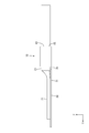
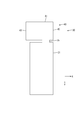
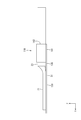
- Right side view of the electric wire with terminal Left side view of the electric wire with terminal Planar development of terminals Rear view of the state before the crimping piece is crimped
- Embodiment 1 will be described with reference to FIGS. 1 to 7.
- the electric wire 10 with a terminal of this embodiment is provided with the electric wire 20 and the terminal 30 connected to the terminal of this electric wire 20, as shown in FIG.1 and FIG.2.
- the Z direction is set to the upper side
- the X direction is set to the right side
- the Y direction is set to the front side.
- the electric wire 20 has a configuration in which an outer periphery of a core wire 21 made of a conductive metal strand is surrounded by an insulating coating 23.
- the electric wire 20 is called a fine wire used for a signal line or the like, and has a thin outer diameter.
- the core wire 21 is exposed by stripping the insulation coating 23 in the front end part of the electric wire 20.
- the electric wire 20 is mounted in the terminal 30 so that it may extend in the front-back direction.
- the terminal 30 is formed by pressing and then bending a conductive metal plate material. As shown in FIG. 1, the terminal 30 includes a welded portion 31 to which the core wire 21 of the electric wire 20 is welded, a caulked portion 40 that caulks the electric wire 20, and a neck portion 35 that connects the welded portion 31 and the caulked portion 40. ing.
- the welded portion 31 has a rectangular shape in plan view, and the dimension in the front-rear direction is longer than the dimension in the width direction.
- the exposed core wire 21 is welded to the right half of the welded portion 31 in the left-right direction (width direction). That is, the core wire 21 is welded at a position that is biased to one side in the width direction of the welded portion 31.
- the neck portion 35 is formed to extend rearward from the rear end of the welded portion 31.
- the right end position of the neck portion 35 is located on the left side of the right end surface 31 ⁇ / b> A of the weld portion 31. That is, the neck portion 35 enters the center side (inside) in the width direction with respect to the welded portion 31.
- the left end position of the neck portion 35 is located on the right side of the center position in the width direction of the welded portion 31. That is, the neck portion 35 extends rearward from a position biased to one side (right side) of the welded portion 31.
- the dimension in the width direction of the neck portion 35 is substantially the same as or slightly smaller than the maximum outer diameter dimension of the electric wire 20.
- the caulking portion 40 includes a bottom plate portion 41, a caulking piece 43, and an auxiliary piece 45.
- the bottom plate portion 41 is continued from the welded portion 31 through the neck portion 35, and the insulating coating 23 of the electric wire 20 is placed thereon.
- the dimension of the bottom plate part 41 in the width direction is smaller than the dimension of the neck part 35 in the width direction. Therefore, the rear end portion of the neck portion 35 is bent so that both side end portions thereof are connected to the caulking piece 43 and the auxiliary piece 45 so as to have the same width as the bottom plate portion 41.
- the caulking piece 43 is provided so as to extend from one (left side) side edge of the bottom plate portion 41 in a direction intersecting the direction in which the electric wire 20 extends (front-rear direction). As shown in FIG. 3, the caulking piece 43 is caulked so as to be wound around the outer periphery of the insulating coating 23 of the electric wire 20.
- the width dimension of the caulking piece 43 is such a dimension that it is wound around about three-fourths of the outer circumference of the electric wire 20.
- the left end position of the caulking piece 43 before bending (deployed state) protrudes slightly to the left from the left end position of the welded portion 31, as shown in FIG.
- the auxiliary piece 45 has a direction (front-rear direction) in which the electric wire 20 extends from the side edge on the side (right side) opposite to the side on which the caulking piece 43 of the bottom plate portion 41 is provided. It is provided to extend in the intersecting direction. Specifically, the auxiliary piece 45 is caulked so as to enter the inside of the caulking piece 43 while being wound around the outer periphery of the insulating coating 23 of the electric wire 20. The width dimension of the auxiliary piece 45 is shorter than the dimension that wraps around about a quarter of the outer circumference of the electric wire 20. 6 and 7, the auxiliary piece 45 is provided on the right side of the neck portion 35.
- the width of the auxiliary piece 45 is such that the neck portion 35 is on the left side of the welded portion 31 in the expanded state.
- the bottom plate portion 41 has a size that is smaller than the neck portion 35 added to the intrusion size.
- the right end surface 45A of the auxiliary piece 45 is flush with the right end surface 31A of the welded portion 31.
- a virtual plane passing through the center O in the radial direction of the electric wire 20 and perpendicular to the bottom plate portion 41 is defined as a first virtual plane P1
- a virtual plane passing through the center O in the radial direction of the electric wire 20 and parallel to the bottom plate portion 41 is used.
- the plane is defined as a second virtual plane P2.
- the tip edge 43 ⁇ / b> A of the caulking piece 43 passes through the first virtual surface P ⁇ b> 1 and is positioned below (the bottom plate portion 41 side) below the second virtual surface P ⁇ b> 2.
- the bottom plate portion 41 is close to the side edge on the opposite side (right side) to the side on which the caulking piece 43 is provided.
- the distal end edge (right end surface 45A) of the auxiliary piece 45 enters the left side (the electric wire 20 side) of the caulking piece 43 while being positioned below the second virtual surface P2. That is, the end portion of the caulking piece 43 overlaps with the end portion of the auxiliary piece 45, and the overlapping position is located below the second virtual plane P2.
- the electric wire with terminal 10 and the terminal 30 of the present embodiment are configured as described above, and the assembling method and operation thereof will be described subsequently.
- the insulating coating 23 is peeled off at the end of the electric wire 20.
- the core wire 21 is exposed to a degree that is slightly shorter than the dimension of the welded portion 31 in the front-rear direction.
- the terminal 30 is punched as shown in FIG. 6 by pressing a conductive metal plate.
- the tip edge 43A (left end position) of the caulking piece 43 protrudes to the left of the left end position of the welded portion 31, but the caulking pieces having the same length in both directions with respect to the bottom plate portion are provided.
- the protrusion dimension the dimension in the width direction is small. That is, compared to the case where the crimping piece extends uniformly from the side edges in both directions of the bottom plate portion, the developed length of the crimping piece 43 (the dimension in the width direction). ) Can be shortened, and the yield can be improved, and the right end surface 31A of the welded portion 31 and the right end surface 45A of the auxiliary piece 45 are flush with each other. Because it is complete, it will lead to further improvement in yield.
- the terminal 30 is bent.
- the caulking piece 43 and the auxiliary piece 45 rise obliquely upward from the bottom plate portion 41 and are bent into U-shapes having different lengths in the left-right direction.
- the electric wire 20 is placed on the terminal 30.
- the core wire 21 of the electric wire 20 extending in the front-rear direction
- the exposed core wire 21 is arranged on the right half of the welded portion 31, and the end of the insulation coating 23 of the electric wire 20 is arranged on the caulked portion 40.
- the core wire 21 is ultrasonically welded to the welded portion 31.
- the electric wire 20 since the electric wire 20 is positioned in the bottom plate portion 41 by the caulking piece 43 and the auxiliary piece 45, the core wire 21 does not move and the ultrasonic welding work can be easily performed.
- the caulking portion 40 is caulked so as to be wound around the outer periphery of the electric wire 20.
- the auxiliary piece 45 is caulked along the outer shape of the electric wire 20, while the caulking piece 43 tip edge 43A passes through the first virtual surface P1 and is lower than the second virtual surface P2 (bottom plate). It is caulked so as to be close to the side edge on the side (right side) opposite to the side on which the caulking piece 43 is provided in the bottom plate portion 41. That is, the front edge 43A of the caulking piece 43 extends in a direction different from the direction (vertical direction) orthogonal to the welded portion 31, and is the opposite side (left side) where the caulking piece 43 in the bottom plate portion 41 is provided.
- the caulking piece 43 is caulked so that the end of the caulking piece 43 overlaps the end of the auxiliary piece 45 below the second virtual plane P2.
- the second imaginary surface P2 that is in close contact with the insulating coating 23 is not above the second imaginary surface P2, but is slightly below the second imaginary surface P2 in which a slight gap is generated between the electric wires 20. Since they are overlapped and crimped on the side, the insulation coating 23 of the electric wire 20 is hardly damaged.
- the caulking portion 40 covers the outer periphery of the electric wire 20, the holding force to the electric wire 20 can be sufficiently secured even with the cantilevered caulking piece 43.
- the auxiliary piece 45 is shorter than the caulking piece 43, and therefore, when the caulking piece extends equally from the side edges in both directions of the bottom plate portion as in the past. In comparison, the dimension in the width direction (deployment length) in the expanded state can be shortened, and the yield can be improved.
- the tip edge of the caulking piece 43 is located on the side of the bottom plate portion 41 with respect to the first virtual plane P1 that passes through the center of the electric wire 20 and is perpendicular to the bottom plate portion 41, and is opposite to the bottom plate portion 41.
- the outer periphery of the insulating coating 23 is wrapped up to the side edge on the side. That is, since the bottom plate portion 41 and the caulking piece 43 are wound around one-half or more of the outer periphery of the electric wire 20, a holding force for the electric wire 20 can be ensured.
- the tip edge of the caulking piece 43 is located on the side of the bottom plate portion 41 with respect to the second virtual plane P2 that passes through the center of the electric wire 20 and is parallel to the bottom plate portion 41, and is opposite to the bottom plate portion 41.
- the outer periphery of the insulating coating 23 is wrapped up to the side edge on the side. That is, since the bottom plate portion 41 and the caulking piece 43 are wound around three-fourths or more of the outer periphery of the electric wire 20, the holding force for the electric wire 20 can be further ensured.
- the caulking piece 43 and the auxiliary piece 45 extend in both directions with respect to the bottom plate portion 41, the electric wire 20 can be positioned when the electric wire 20 is placed on the bottom plate portion 41.
- Embodiment 2 will be described with reference to FIGS.
- the shape of the caulking portion 140 is different from that of the first embodiment.
- description is abbreviate
- the vertical and horizontal directions are the same as those in the first embodiment.
- the electric wire with terminal 110 includes an electric wire 20 and a terminal 130.
- the terminal 130 is formed by pressing a conductive metal plate material and then bending it. As shown in FIG. 8, the terminal 130 includes a welded portion 31 to which the core wire 21 of the electric wire 20 is welded, a caulked portion 140 that caulks the electric wire 20, and a neck portion 135 that connects the welded portion 31 and the caulked portion 140. ing.
- the neck portion 135 is formed by extending backward from the rear end of the welded portion 31.
- the right end position of the neck portion 35 is flush with the right end surface 31A of the welded portion 31, and is flush with the right end surface 141A of the bottom plate portion 141 of the caulking portion 140.
- the dimension of the neck portion 135 in the width direction is substantially the same as or slightly smaller than the maximum outer diameter dimension of the electric wire 20.
- the position of the electric wire 20 is determined by the position of the neck portion 135 and the caulking portion 140 connected thereto, and the core wire 21 of the electric wire 20 is welded to the right end portion of the welded portion 31.
- the caulking portion 140 includes a bottom plate portion 141 and a caulking piece 143.
- the bottom plate portion 141 is continued from the welded portion 31 through the neck portion 135, and the insulating coating 23 of the electric wire 20 is placed thereon.
- the bottom plate portion 141 has a left end connected to the caulking piece 143, while an upper surface of the right end portion serves as an abutting surface 147 against which the abutting surface 143 ⁇ / b> B of the caulking piece 143 is abutted.
- the caulking piece 143 is provided so as to extend from one (left side) side edge of the bottom plate portion 141 in a direction intersecting with the direction in which the electric wire 20 extends (front-rear direction). Specifically, the caulking piece 143 is caulked so as to be wound around the outer periphery of the insulating coating 23 of the electric wire 20.
- the width dimension of the caulking piece 143 is such a dimension that the abutting surface 143B abuts against the abutted surface 147 of the bottom plate portion 141 after being wound around the outer periphery of the electric wire 20.
- the left end position of the caulking piece 143 before bending (deployed state) is the same as the left end position of the welded portion 31, as shown in FIG.
- the caulking portion 140 is wound around the outer periphery of the electric wire 20.
- the leading edge 143A of the caulking piece 143 passes through the first virtual surface P1 and is positioned below (the bottom plate portion 141 side) below the second virtual surface P2.
- the abutting surface 143B of the caulking piece 143 is in contact with the abutting surface 147 which is the upper surface of the side edge portion on the opposite side (right side) of the bottom plate portion 141 on the side where the caulking piece 143 is provided.
- the front edge 143A of the caulking piece 143 extends in a direction different from the direction (vertical direction) orthogonal to the welded portion 31, and is the opposite side (right side) of the bottom plate portion 141 where the caulking piece 143 is provided. ) In the vicinity of the side edge of the bottom plate portion 141.
- the electric wire with terminal 110 and the terminal 130 of the present embodiment are configured as described above, and the assembling method and operation will be described subsequently.
- the terminal 130 is punched as shown in FIG.
- the front end edge 43A (left end position) of the caulking piece 143 is the same as the left end position of the welded portion 31, and the development length (dimension in the width direction) of the caulking piece 143 can be shortened. Yield can be improved.
- the right end surface 31A of the welded portion 31, the right end surface of the neck portion 135, and the right end surface 141A of the bottom plate portion are flush with each other. Therefore, at least the right end face is aligned, which leads to further improvement in yield.
- the terminal 130 is bent.
- the caulking piece 143 is bent so as to rise obliquely from the bottom plate portion 141 in the upper left direction.
- the electric wire 20 is placed on the terminal 130.
- the core wire 21 of the electric wire 20 extending in the front-rear direction
- the exposed core wire 21 is arranged at the right end portion of the welded portion 31, and the end of the insulating coating 23 of the electric wire 20 is arranged on the bottom plate portion 141 of the caulking portion 140.
- the core wire 21 is ultrasonically welded to the welded portion 31.
- the caulking portion 140 is caulked so as to be wound around the outer periphery of the electric wire 20.
- the leading edge 143A of the caulking piece 143 passes through the first imaginary plane P1 and is lower than the second imaginary plane P2 (on the side of the bottom plate portion 141), and is the side where the caulking piece 143 in the bottom plate portion 141 is provided.
- the crimping surface 143B of the crimping piece 143 is crimped to the butted surface 147 which is the upper surface of the side edge on the opposite side (right side).
- the end face (butting surface 143B) of the caulking piece 143 is in contact with the abutted surface 147, the insulating coating 23 of the electric wire 20 is hardly damaged by the corners of the end face.
- the caulking portion 40 covers the outer periphery of the electric wire 20, a sufficient holding force to the electric wire 20 can be secured even with the cantilevered caulking piece 143.
- the caulking piece 143 extends from the bottom plate portion 141, the dimension in the width direction (deployment length) in the unfolded state can be shortened, and the yield can be reduced. Can be improved.
- the right end surface 31A of the welded portion 31 and the right end surface 141A of the bottom plate portion 141 are flush with each other in a flattened state, and the developed length of the caulking portion 140 is within the width dimension of the welded portion 31. Therefore, the yield can be further improved.
- the caulking portions 40 and 140 are wound with the caulking pieces 43 and 143 so as to surround the entire outer periphery of the electric wire 20, but the caulking pieces 43 and 143 and the auxiliary piece 45 or the bottom plate portion 141 are wound. There may be a gap between
- the right end surface 31A of the welded portion 31 and the right end surface 45A of the auxiliary piece 45 or the right end surface 141A of the bottom plate portion 141 are flush with each other. However, it does not have to be flush.
- the core wire 21 is welded to the welded portion 31 by ultrasonic welding, but may be welded by other methods such as resistance welding.
- the neck portions 35 and 135 are provided, but the bottom plate portions 41 and 141 of the caulking portions 40 and 140 are directly connected to the welded portion 31 without providing the neck portion. good.
Landscapes
- Engineering & Computer Science (AREA)
- Manufacturing & Machinery (AREA)
- Connections Effected By Soldering, Adhesion, Or Permanent Deformation (AREA)
Abstract
芯線21の外周が絶縁被覆23で包囲された電線20の端部から露出した前記芯線21に端子30が接続された端子付き電線10であって、前記端子30は、前記芯線21が溶接された平板状の溶接部31と、前記溶接部31に連なると共に前記電線20の前記絶縁被覆23が載置された底板部41と、前記底板部41の一方の側縁から、前記底板部41に載置された前記電線20が延びる方向と交差する方向に延びるかしめ片43と、を備え、前記かしめ片43が前記電線20の前記絶縁被覆23の外周に巻き付くようにかしめられた状態で、前記かしめ片43の先端縁43Aが、前記電線の中心Oを通り前記底板部41と垂直な第1仮想面P1よりも前記底板部41側に位置し、前記底板部41における前記かしめ片43が設けられている側とは反対側の側縁に近接する。
Description
本発明は、端子付き電線及び端子に関する。
一般的に、端子は電線の端末に接続される際に、電線の芯線と電気的に接続される部分と、芯線が被覆に覆われた部分を保持する部分が設けられている。芯線が被覆に覆われた部分を保持する部分は、電線にかかる力が、芯線との接続部分にかかるのを抑制する役割を果たす一方で、電線の絶縁被覆を傷つけにくいように工夫されている。例えば、特開2013-4406号公報に開示された従来の端子は、芯線が溶接される部分と、絶縁被覆の外周を両側から包み込むようにかしめられるインシュレーションバレルとを備えている。そして、インシュレーションバレルは、全体として電線の外周よりも長くなるように冗長部分が設けられており、冗長部分を設けることで絶縁被覆にかかる力を調整して、電線を保持する力を確保しつつ、絶縁被覆を傷つけにくくしている。
しかしながら、特開2013-4406号公報(上記特許文献1)に記載の従来の端子では、インシュレーションバレルは端子の軸線方向に直交する方向(幅方向)の両側に延びているため、板材から端子を打ち抜く際の幅方向の寸法(展開長)が大きくなる。そのため、端子の形状によっては、インシュレーションバレルの展開長が最も大きくなる。つまり、両方向に延びるインシュレーションバレルの展開長の大きさが、端子の歩留まり悪化の要因、つまりコストアップの要因となっていた。
本明細書で開示される端子付き電線は、芯線の外周が絶縁被覆で包囲された電線の端部から露出した前記芯線に端子が接続された端子付き電線であって、前記端子は、前記芯線が溶接された平板状の溶接部と、前記溶接部に連なると共に前記電線の前記絶縁被覆が載置された底板部と、前記底板部の一方の側縁から、前記底板部に載置された前記電線が延びる方向と交差する方向に延びるかしめ片と、を備え、前記かしめ片が前記電線の前記絶縁被覆の外周に巻き付くようにかしめられた状態で、前記かしめ片の先端縁が、前記電線の中心を通り前記底板部と垂直な第1仮想面よりも前記底板部側に位置し、前記底板部における前記かしめ片が設けられている側とは反対側の側縁に近接する。
このような構成によると、電線の絶縁被覆に巻き付くようにかしめられるかしめ片が底板部の一方の側縁から延びるように設けられている。そのため、底板部の両方向の側縁からかしめ片が延びる場合に比べて、かしめ片の展開長を短くすることができる。また、かしめ片の先端縁が、電線の中心を通り底板部と垂直になる第1仮想面よりも底板部側に位置し、かつ底板部の反対側の側縁に近接するまで絶縁被覆の外周を包み込んでいる。つまり、底板部とかしめ片によって電線の外周の2分の1以上に巻き付いているため、電線に対する保持力を確保することができる。
本明細書に開示される端子付き電線の実施の態様として、以下の構成としてもよい。
前記かしめ片が前記電線の前記絶縁被覆の外周に巻き付くようにかしめられた状態で、前記かしめ片の先端縁が、前記電線の中心を通り前記底板部と平行になる第2仮想面よりも前記底板部側に位置し、前記底板部における前記かしめ片が設けられている側とは反対側の側縁に近接する構成としても良い。
前記かしめ片が前記電線の前記絶縁被覆の外周に巻き付くようにかしめられた状態で、前記かしめ片の先端縁が、前記電線の中心を通り前記底板部と平行になる第2仮想面よりも前記底板部側に位置し、前記底板部における前記かしめ片が設けられている側とは反対側の側縁に近接する構成としても良い。
このような構成によると、かしめ片の先端縁が、電線の中心を通り底板部と平行になる仮想面よりも底板部側に位置し、かつ底板部の反対側の側縁に近接するまで絶縁被覆の外周を包み込んでいる。つまり、底板部とかしめ片によって電線の外周の4分の3以上に巻き付いているため、電線に対する保持力をさらに確保することができる。
前記電線が前記かしめ片にかしめられた状態で、前記かしめ片の端面が前記底板部に突き当てられる構成としても良い。
このような構成では、かしめ片が電線の外周を覆って底板部に突き当てられているため、電線を保持する力を向上することができる。また、底板部から延びるのがかしめ片だけのため、展開長を短くすることができる。
前記底板部の前記かしめ片が設けられている側と反対側の側縁には、前記底板部に載置された前記電線が延びる方向と交差する方向に延び、かつ前記かしめ片よりも短い補助片が設けられており、前記電線が前記かしめ片にかしめられた状態で、前記かしめ片の端部と前記補助片の端部が重なり合う構成としても良い。
このような構成では、かしめ片の端部と補助片の端部が重なり合うために、保持力を向上することができる。また、底板部に対して両方向にかしめ片と補助片が延びているため、電線を底板部に載置する際に、電線の位置決めが可能になる。一方、補助片はかしめ片に比べて短いため、従来のように両方向の側縁から均等にかしめ片が延びている場合に比べて、展開長を短くすることができる。
前記溶接部の端面と前記底板部の端面とが平板状に展開された状態で面一となっている構成としても良い。
このような構成では、溶接部の端面と底板部の端面とが面一となっていることから、幅方向の位置が少なくとも一方は揃うため、歩留まりを向上することができる。
前記溶接部の端面と前記補助片の端面とが平板状に展開された状態で面一となっている構成としても良い。
このような構成では、溶接部の端面と補助片の端面とが面一となっていることから、幅方向の位置が少なくとも一方は揃うため、歩留まりを向上することができる。
また、本明細書で開示される端子は、電線の芯線が溶接される平板状の溶接部と、前記溶接部に連なると共に前記電線の絶縁被覆で包囲された部分が載置される底板部と、前記底板部の一方の側縁から、前記底板部に載置された前記電線が延びる方向と交差する方向に延びるかしめ片と、を備え、前記かしめ片が前記電線の外周に巻き付くようにかしめられた状態で、前記かしめ片の先端縁が、前記溶接部と直交する方向とは異なる方向に延びており、かつ前記底板部における前記かしめ片が設けられたのとは反対側の側縁に近接する。
本明細書に開示される端子の実施の態様として、以下の構成としてもよい。
前記電線が前記かしめ片にかしめられた状態で、前記かしめ片の端面が前記底板部に突き当てられる構成としても良い。
前記電線が前記かしめ片にかしめられた状態で、前記かしめ片の端面が前記底板部に突き当てられる構成としても良い。
前記底板部の前記かしめ片が設けられている側と反対側の側縁には、前記底板部に載置された前記電線が延びる方向と交差する方向に延び、かつ前記かしめ片よりも短い補助片が設けられており、前記電線が前記かしめ片にかしめられた状態で、前記かしめ片の端部と前記補助片の端部が重なり合う構成としても良い。
前記溶接部の端面と前記底板部の端面とが平板状に展開された状態で面一となっている構成としても良い。
前記溶接部の端面と前記補助片の端面とが平板状に展開された状態で面一となっている構成としても良い。
本明細書に開示される端子付き電線及び端子によれば、端子が電線をかしめる部分の展開長を短くすることができる。
<実施形態1>
実施形態1を図1から図7の図面を参照しながら説明する。
本実施形態の端子付き電線10は、図1及び図2に示すように、電線20と、この電線20の端末に接続された端子30とを備えている。以下の説明では、上下方向については、Z方向を上方とし、左右方向については、X方向を右方とし、前後方向については、Y方向を前方とする。
実施形態1を図1から図7の図面を参照しながら説明する。
本実施形態の端子付き電線10は、図1及び図2に示すように、電線20と、この電線20の端末に接続された端子30とを備えている。以下の説明では、上下方向については、Z方向を上方とし、左右方向については、X方向を右方とし、前後方向については、Y方向を前方とする。
電線20は、図2に示すように、導電性の金属素線からなる芯線21の外周を絶縁被覆23で包囲した構成である。電線20は、信号線などに用いられる細線と呼ばれるもので、その外径が細いものとなっている。また、電線20は、その前端部において、絶縁被覆23が皮剥ぎされることで、芯線21が露出されている。そして、電線20は、前後方向に延びるように端子30に載置されている。
端子30は、導電性の金属板材をプレス加工後、折り曲げ加工して形成される。端子30は、図1に示すように、電線20の芯線21が溶接される溶接部31と、電線20をかしめるかしめ部40と、溶接部31とかしめ部40とを繋ぐ首部35とを備えている。
溶接部31は、図1及び図2に示すように、平面視矩形状となっており、前後方向の寸法が幅方向の寸法よりも長くなっている。そして、露出された芯線21は、溶接部31の左右方向(幅方向)の右半分に溶接されている。つまり、芯線21は、溶接部31の幅方向の一方に偏った位置に溶接されている。
首部35は、図1に示すように、溶接部31の後端から後方に延びて形成されている。首部35の右端位置は、溶接部31の右端面31Aよりも左側に位置している。つまり、首部35は、溶接部31よりも幅方向中央側(内側)に入りこんでいる。また、首部35の左端位置は、溶接部31の幅方向の中央位置よりも右側に位置している。つまり、首部35は、溶接部31の一方(右側)に偏った位置から後方に延びている。また、首部35の幅方向の寸法は、電線20の最大外径寸法とほぼ同じか若干小さくなっている。
かしめ部40は、図1及び図7に示すように、底板部41と、かしめ片43と、補助片45とを備えている。底板部41は、溶接部31から首部35を介して連なっており、電線20の絶縁被覆23が載置されている。底板部41の幅方向の寸法は、首部35の幅方向の寸法よりも小さくなっている。そのため、首部35の後端部は、底板部41と等幅になるようにその両側端部が若干かしめ片43及び補助片45に連なるように曲げられている。
かしめ片43は、図7に示すように、底板部41の一方(左側)の側縁から、電線20が延びる方向(前後方向)と交差する方向に延びるように設けられている。図3に示すように、このかしめ片43は、電線20の絶縁被覆23の外周に巻き付くようにかしめられている。かしめ片43の幅寸法は、電線20の外周の約4分の3に巻き付く程度の寸法となっている。また、曲げ加工前(展開状態)でのかしめ片43の左端位置は、図6に示すように、溶接部31の左端位置よりも若干左側に突出している。
補助片45は、図1及び図7に示すように、底板部41のかしめ片43が設けられている側とは反対側(右側)の側縁から、電線20が延びる方向(前後方向)と交差する方向に延びるように設けられている。具体的には、補助片45は、電線20の絶縁被覆23の外周に巻き付きつつ、かしめ片43の内側に入りこむようにかしめられている。補助片45の幅寸法は、電線20の外周の約4分の1に巻き付く程度の寸法よりも短くなっている。そして、補助片45は、図6及び図7に示すように、首部35よりも右側に設けられており、補助片45の幅寸法は、展開状態において、首部35が溶接部31よりも左側に入りこんだ寸法に底板部41が首部35よりも小さい分の寸法を加えた寸法となっている。また、展開状態において、補助片45の右端面45Aは、溶接部31の右端面31Aと面一になっている。
図3に示すように、かしめ部40が電線20の外周に巻き付いた状態について説明する。ここで、電線20の径方向の中心Oを通り底板部41に垂直な仮想的な平面を第1仮想面P1とし、電線20の径方向の中心Oを通り底板部41に平行な仮想的な平面を第2仮想面P2とする。かしめ部40が電線20の外周に巻き付いた状態では、かしめ片43の先端縁43Aが、第1仮想面P1を通過して、第2仮想面P2よりも下側(底板部41側)に位置し、底板部41におけるかしめ片43が設けられている側とは反対側(右側)の側縁に近接している。一方、補助片45の先端縁(右端面45A)は、第2仮想面P2よりも下側に位置しつつ、かしめ片43よりも左側(電線20側)に入りこんでいる。つまり、かしめ片43の端部は、補助片45の端部にオーバーラップするように重なり合っており、その重なり合う位置は、第2仮想面P2よりも下側に位置している。
本実施形態の端子付き電線10及び端子30は、以上のような構成であって、続いてその組み付け方法及び作用を説明する。
まず、電線20の端部において、絶縁被覆23を皮剥ぎする。この際に、溶接部31の前後方向の寸法よりも若干短くなる程度に芯線21を露出させる。
まず、電線20の端部において、絶縁被覆23を皮剥ぎする。この際に、溶接部31の前後方向の寸法よりも若干短くなる程度に芯線21を露出させる。
一方で、導電性の金属板材をプレス加工することで、図6に示すように、端子30を打ち抜く。この際に、かしめ片43の先端縁43A(左端位置)は、溶接部31の左端位置よりも左側に突出しているが、底板部に対して両方向に同じ長さのかしめ片を設けているものに比べれば、その突出寸法(幅方向の寸法は小さくなっている。つまり、底板部の両方向の側縁から均等にかしめ片が延びる場合に比べて、かしめ片43の展開長(幅方向の寸法)を短くすることができ、歩留まりを向上させることができる。また、溶接部31の右端面31Aと、補助片45の右端面45Aとが面一となっている。そのため、少なくとも右側の端面は揃っていることから、歩留まりの更なる向上につながる。
次に、図7に示すように、端子30を曲げ加工する。かしめ片43と補助片45が底板部41から斜め上方向に立ち上がって、左右方向で長さの違うU字状に曲げ加工される。そして、電線20を端子30に載置する。電線20の芯線21が前後方向に延びる状態で、露出した芯線21を溶接部31の右半分に配置し、電線20の絶縁被覆23の端末をかしめ部40に配置する。そして、溶接部31に対して芯線21を超音波溶接する。この際に、電線20がかしめ片43と補助片45によって底板部41内に位置決めされるため、芯線21が移動せずに超音波溶接の作業が行いやすくなる。
そして、かしめ部40を電線20の外周に巻き付けるようにしてかしめる。この際に、補助片45を電線20の外形に沿うようにかしめる一方で、かしめ片43先端縁43Aが、第1仮想面P1を通過して、第2仮想面P2よりも下側(底板部41側)であって、底板部41におけるかしめ片43が設けられている側とは反対側(右側)の側縁に近接するようにかしめる。つまり、かしめ片43の先端縁43Aが、溶接部31と直交する方向(上下方向)とは異なる方向に延びており、かつ底板部41におけるかしめ片43が設けられたのとは反対側(左側)の側縁に近接している。そして、かしめ片43の端部が補助片45の端部に第2仮想面P2よりも下側でオーバーラップするように、かしめ片43がかしめられる。このように、保持力を確保するためにしっかりと絶縁被覆23と密着する第2仮想面P2よりも上側ではなく、電線20との間に若干の隙間が生じている第2仮想面P2より下側で重なり合ってかしめられているために、電線20の絶縁被覆23を傷つけにくくなっている。また、電線20の外周をかしめ部40が覆っているために、片持ち状のかしめ片43であっても電線20への保持力を十分に確保することができる。
以上のように、実施形態1の端子付き電線10では、補助片45はかしめ片43に比べて短いため、従来のように底板部の両方向の側縁から均等にかしめ片が延びている場合に比べて、展開状態での幅方向の寸法(展開長)を短くすることができ、歩留まりを向上できる。
また、本実施形態においては、かしめ片43の先端縁が、電線20の中心を通り底板部41と垂直になる第1仮想面P1よりも底板部41側に位置し、かつ底板部41の反対側の側縁に近接するまで絶縁被覆23の外周を包み込んでいる。つまり、底板部41とかしめ片43によって電線20の外周の2分の1以上に巻き付いているため、電線20に対する保持力を確保することができる。特に、溶接部31の板面に垂直な方向に電線20を引きはがす力が電線20に加えられた場合において、上記のかしめ片43によって、電線20は底板部41と垂直な方向から押さえられている。これにより、芯線21と溶接部31とが溶接(超音波溶接)されている場合に、芯線21と溶接部31とが剥離することが抑制される。
更に、本実施形態においては、かしめ片43の先端縁が、電線20の中心を通り底板部41と平行になる第2仮想面P2よりも底板部41側に位置し、かつ底板部41の反対側の側縁に近接するまで絶縁被覆23の外周を包み込んでいる。つまり、底板部41とかしめ片43によって電線20の外周の4分の3以上に巻き付いているため、電線20に対する保持力をさらに確保することができる。
さらに、かしめ片43の端部と補助片45の端部が重なり合うために、電線20への保持力を十分に確保できる。
また、溶接部31の右端面31Aと補助片45の右端面45Aとが平板状に展開された状態で面一となっているため、歩留まりをさらに向上できる。
また、底板部41に対して両方向にかしめ片43と補助片45が延びているため、電線20を底板部41に載置する際に、電線20の位置決めが可能になる。
<実施形態2>
次に、実施形態2を図8から図13によって説明する。
実施形態2の端子付き電線110では、かしめ部140の形状が、実施形態1とは相違する。なお、実施形態1と同一機能を有する部材、部位については、同一の符号を付すことで、説明を省略しまたは簡略化する。また、上下左右前後方向については、実施形態1と同じ方向とする。
次に、実施形態2を図8から図13によって説明する。
実施形態2の端子付き電線110では、かしめ部140の形状が、実施形態1とは相違する。なお、実施形態1と同一機能を有する部材、部位については、同一の符号を付すことで、説明を省略しまたは簡略化する。また、上下左右前後方向については、実施形態1と同じ方向とする。
端子付き電線110は、電線20と端子130とを備えている。端子130は、導電性の金属板材をプレス加工後、折り曲げ加工して形成される。端子130は、図8に示すように、電線20の芯線21が溶接される溶接部31と、電線20をかしめるかしめ部140と、溶接部31とかしめ部140とを繋ぐ首部135とを備えている。
首部135は、図8に示すように、溶接部31の後端から後方に延びることで形成されている。首部35の右端位置は、溶接部31の右端面31Aと面一で、かしめ部140の底板部141の右端面141Aとも面一になっている。また、首部135の幅方向の寸法は、電線20の最大外径寸法とほぼ同じか若干小さくなっている。また、首部135及びそれに連なるかしめ部140の位置によって電線20の位置が決まっており、電線20の芯線21は溶接部31の右端部に熔接されている。
かしめ部140は、図8及び図10に示すように、底板部141と、かしめ片143とを備えている。底板部141は、溶接部31から首部135を介して連なっており、電線20の絶縁被覆23が載置されている。底板部141は、左端部がかしめ片143に連なるようになっている一方で、右端部の上面は、かしめ片143の突き当て面143Bが突き当てられる被突き当て面147となっている。
かしめ片143は、図8及び図10に示すように、底板部141の一方(左側)の側縁から、電線20が延びる方向(前後方向)と交差する方向に延びるように設けられている。具体的には、かしめ片143は、電線20の絶縁被覆23の外周に巻き付くようにかしめられている。かしめ片143の幅寸法は、電線20の外周に巻き付いた後に底板部141の被突き当て面147に突き当て面143Bが突き当たる程度の寸法となっている。また、曲げ加工前(展開状態)でのかしめ片143の左端位置は、図13に示すように、溶接部31の左端位置と同じになっている。
図10に示すように、かしめ部140が電線20の外周に巻き付いた状態について説明する。かしめ部140が電線20の外周に巻き付いた状態では、かしめ片143の先端縁143Aが、第1仮想面P1を通過して、第2仮想面P2よりも下側(底板部141側)に位置し、底板部141におけるかしめ片143が設けられている側とは反対側(右側)の側縁部の上面である被突き当て面147にかしめ片143の突き当て面143Bが突き当たっている。つまり、かしめ片143の先端縁143Aが、溶接部31と直交する方向(上下方向)とは異なる方向に延びており、かつ底板部141におけるかしめ片143が設けられたのとは反対側(右側)の側縁に近接して、底板部141の被突き当て面147に突き当たっている。
本実施形態の端子付き電線110及び端子130は、以上のような構成であって、続いてその組み付け方法及び作用を説明する。
導電性の金属板材をプレス加工することで、図13に示すように、端子130を打ち抜く。この際に、かしめ片143の先端縁43A(左端位置)は、溶接部31の左端位置と同じでとなっており、かしめ片143の展開長(幅方向の寸法)を短くすることができ、歩留まりを向上させることができる。また、溶接部31の右端面31Aと、首部135の右端面と底板部の右端面141Aとが面一となっている。そのため、少なくとも右側の端面は揃っていることから、歩留まりの更なる向上につながる。
導電性の金属板材をプレス加工することで、図13に示すように、端子130を打ち抜く。この際に、かしめ片143の先端縁43A(左端位置)は、溶接部31の左端位置と同じでとなっており、かしめ片143の展開長(幅方向の寸法)を短くすることができ、歩留まりを向上させることができる。また、溶接部31の右端面31Aと、首部135の右端面と底板部の右端面141Aとが面一となっている。そのため、少なくとも右側の端面は揃っていることから、歩留まりの更なる向上につながる。
次に、端子130を曲げ加工する。かしめ片143が底板部141から斜め左上方向に立ち上がるように曲げ加工される。そして、電線20を端子130に載置する。電線20の芯線21が前後方向に延びる状態で、露出した芯線21を溶接部31の右端部に配置し、電線20の絶縁被覆23の端末をかしめ部140の底板部141に配置する。そして、溶接部31に対して芯線21を超音波溶接する。
そして、かしめ部140を電線20の外周に巻き付けるようにしてかしめる。かしめ片143先端縁143Aが、第1仮想面P1を通過して、第2仮想面P2よりも下側(底板部141側)であって、底板部141におけるかしめ片143が設けられている側とは反対側(右側)の側縁部の上面である被突き当て面147にかしめ片143の突き当て面143Bが突き当たるようにかしめる。このように、かしめられたかしめ片143の端面(突き当て面143B)が被突き当て面147に突き当たっていることから、端面の角などによって電線20の絶縁被覆23を傷つけにくくなっている。また、電線20の外周をかしめ部40が覆っているために、片持ち状のかしめ片143であっても電線20への保持力を十分に確保することができる。
以上のように、本実施形態の端子付き電線10では、底板部141から延びるのがかしめ片143だけのため、展開状態での幅方向の寸法(展開長)を短くすることができ、歩留まりを向上できる。
また、溶接部31の右端面31Aと底板部141の右端面141Aとが平板状に展開された状態で面一となっており、溶接部31の幅寸法内でかしめ部140の展開長が収まっているため、歩留まりをさらに向上できる。
一方で、かしめ片143の端面(突き当て面143B)が底板部141の被突き当て面147に突き当たっているために、電線20への保持力を十分に確保できる。
<他の実施形態>
本明細書によって開示される技術は上記記述及び図面によって説明した実施形態に限定されるものではなく、例えば次のような種々の態様も含まれる。
(1)上記実施形態1及び2では、かしめ片43、143の先端縁43A、143Aは第2仮想面P2より下側に位置していたが、第1仮想面P1を通過してれば第2仮想面P2に至っていなくても良い。
本明細書によって開示される技術は上記記述及び図面によって説明した実施形態に限定されるものではなく、例えば次のような種々の態様も含まれる。
(1)上記実施形態1及び2では、かしめ片43、143の先端縁43A、143Aは第2仮想面P2より下側に位置していたが、第1仮想面P1を通過してれば第2仮想面P2に至っていなくても良い。
(2)上記実施形態1、2では、かしめ部40、140は電線20の外周をすべて囲うようにかしめ片43、143が巻き付いていたが、かしめ片43、143と補助片45もしくは底板部141との間に隙間があいていても良い。
(3)上記実施形態1、2では、溶接部31の右端面31Aと補助片45の右端面45Aもしくは底板部141の右端面141Aとが平板状に展開された状態で面一となっていたが、面一でなくても良い。
(4)上記実施形態1、2では、芯線21は溶接部31に超音波溶接によって溶接されていたが、抵抗溶接等他の方法で溶接されていても良い。
(5)上記実施形態1、2では、首部35、135が設けられていたが、首部を設けずに溶接部31に直接かしめ部40、140の底板部41、141が連節されていても良い。
10、110:端子付き電線
20:電線
21:芯線
23:絶縁被覆
30、130:端子
31:溶接部
31A:右端面
35、135:首部
40、140:かしめ部
41、141:底板部
141A:右端面
43、143:かしめ片
43A、143A:先端縁
143B:突き当て面
45:補助片
45A:右端面
147:被突き当て面
O:電線の径方向の中心
P1:第1仮想面
P2:第2仮想面
20:電線
21:芯線
23:絶縁被覆
30、130:端子
31:溶接部
31A:右端面
35、135:首部
40、140:かしめ部
41、141:底板部
141A:右端面
43、143:かしめ片
43A、143A:先端縁
143B:突き当て面
45:補助片
45A:右端面
147:被突き当て面
O:電線の径方向の中心
P1:第1仮想面
P2:第2仮想面
Claims (11)
- 芯線の外周が絶縁被覆で包囲された電線の端部から露出した前記芯線に端子が接続された端子付き電線であって、
前記端子は、
前記芯線が溶接された平板状の溶接部と、
前記溶接部に連なると共に前記電線の前記絶縁被覆が載置された底板部と、
前記底板部の一方の側縁から、前記底板部に載置された前記電線が延びる方向と交差する方向に延びるかしめ片と、を備え、
前記かしめ片が前記電線の前記絶縁被覆の外周に巻き付くようにかしめられた状態で、前記かしめ片の先端縁が、前記電線の中心を通り前記底板部と垂直な第1仮想面よりも前記底板部側に位置し、前記底板部における前記かしめ片が設けられている側とは反対側の側縁に近接する端子付き電線。 - 前記かしめ片が前記電線の前記絶縁被覆の外周に巻き付くようにかしめられた状態で、前記かしめ片の先端縁が、前記電線の中心を通り前記底板部と平行になる第2仮想面よりも前記底板部側に位置し、前記底板部における前記かしめ片が設けられている側とは反対側の側縁に近接する請求項1に記載の端子付き電線。
- 前記電線が前記かしめ片にかしめられた状態で、前記かしめ片の端面が前記底板部に突き当てられる請求項1または請求項2に記載の端子付き電線。
- 前記底板部の前記かしめ片が設けられている側と反対側の側縁には、前記底板部に載置された前記電線が延びる方向と交差する方向に延び、かつ前記かしめ片よりも短い補助片が設けられており、
前記電線が前記かしめ片にかしめられた状態で、前記かしめ片の端部と前記補助片の端部が重なり合う請求項1または請求項2に記載の端子付き電線。 - 前記溶接部の端面と前記底板部の端面とが平板状に展開された状態で面一となっている請求項1から請求項3のいずれか一項に記載の端子付き電線。
- 前記溶接部の端面と前記補助片の端面とが平板状に展開された状態で面一となっている請求項4に記載の端子付き電線。
- 電線の芯線が溶接される平板状の溶接部と、
前記溶接部に連なると共に前記電線の絶縁被覆で包囲された部分が載置される底板部と、
前記底板部の一方の側縁から、前記底板部に載置された前記電線が延びる方向と交差する方向に延びるかしめ片と、を備え、
前記かしめ片が前記電線の外周に巻き付くようにかしめられた状態で、前記かしめ片の先端縁が、前記溶接部と直交する方向とは異なる方向に延びており、かつ前記底板部における前記かしめ片が設けられたのとは反対側の側縁に近接する端子。 - 前記電線が前記かしめ片にかしめられた状態で、前記かしめ片の端面が前記底板部に突き当てられる請求項7に記載の端子。
- 前記底板部の前記かしめ片が設けられている側と反対側の側縁には、前記底板部に載置された前記電線が延びる方向と交差する方向に延び、かつ前記かしめ片よりも短い補助片が設けられており、
前記電線が前記かしめ片にかしめられた状態で、前記かしめ片の端部と前記補助片の端部が重なり合う請求項7に記載の端子。 - 前記溶接部の端面と前記底板部の端面とが平板状に展開された状態で面一となっている請求項7または請求項8に記載の端子。
- 前記溶接部の端面と前記補助片の端面とが平板状に展開された状態で面一となっている請求項9に記載の端子。
Priority Applications (2)
| Application Number | Priority Date | Filing Date | Title |
|---|---|---|---|
| CN201780028357.2A CN109075459B (zh) | 2016-05-10 | 2017-04-19 | 带端子的电线及端子 |
| US16/097,940 US10476175B2 (en) | 2016-05-10 | 2017-04-19 | Terminal-equipped electric wire, and terminal |
Applications Claiming Priority (2)
| Application Number | Priority Date | Filing Date | Title |
|---|---|---|---|
| JP2016094438A JP6766437B2 (ja) | 2016-05-10 | 2016-05-10 | 端子付き電線及び端子 |
| JP2016-094438 | 2016-05-10 |
Publications (1)
| Publication Number | Publication Date |
|---|---|
| WO2017195547A1 true WO2017195547A1 (ja) | 2017-11-16 |
Family
ID=60266985
Family Applications (1)
| Application Number | Title | Priority Date | Filing Date |
|---|---|---|---|
| PCT/JP2017/015665 Ceased WO2017195547A1 (ja) | 2016-05-10 | 2017-04-19 | 端子付き電線及び端子 |
Country Status (4)
| Country | Link |
|---|---|
| US (1) | US10476175B2 (ja) |
| JP (1) | JP6766437B2 (ja) |
| CN (1) | CN109075459B (ja) |
| WO (1) | WO2017195547A1 (ja) |
Families Citing this family (5)
| Publication number | Priority date | Publication date | Assignee | Title |
|---|---|---|---|---|
| JP6356376B1 (ja) * | 2017-05-31 | 2018-07-11 | Connect Fusion 合同会社 | 電線の接続構造及び補助端子 |
| JP7041180B2 (ja) | 2020-02-10 | 2022-03-23 | 矢崎総業株式会社 | 電線の接続構造及び接続方法 |
| JP7402419B2 (ja) * | 2020-09-16 | 2023-12-21 | 住友電装株式会社 | 端子付き電線 |
| JP2022106091A (ja) * | 2021-01-06 | 2022-07-19 | 日本航空電子工業株式会社 | ケーブル組立体の製造方法、その方法に用いられるホーンチップ及びその方法により製造されるケーブル組立体 |
| JP7833909B2 (ja) * | 2022-03-01 | 2026-03-23 | 古河電気工業株式会社 | 接続金具付電線及びその製造方法 |
Citations (3)
| Publication number | Priority date | Publication date | Assignee | Title |
|---|---|---|---|---|
| JPH0992348A (ja) * | 1995-09-22 | 1997-04-04 | Yazaki Corp | 電線固定部付きブスバー及びブスバーへの電線接続方法 |
| JP4966130B2 (ja) * | 2007-08-10 | 2012-07-04 | 長野日本無線株式会社 | 圧着端子 |
| JP2014107104A (ja) * | 2012-11-27 | 2014-06-09 | Sumitomo Wiring Syst Ltd | 端子金具 |
Family Cites Families (6)
| Publication number | Priority date | Publication date | Assignee | Title |
|---|---|---|---|---|
| JP4970093B2 (ja) * | 2006-08-01 | 2012-07-04 | 矢崎総業株式会社 | 取付構造 |
| WO2009112881A1 (en) * | 2008-03-11 | 2009-09-17 | Fci | Electrical terminal system |
| EP2458694B1 (en) * | 2010-11-24 | 2013-06-26 | Tyco Electronics Nederland B.V. | Terminal assembly and method for connecting an electric wire to a terminal element |
| JP5601259B2 (ja) * | 2011-03-24 | 2014-10-08 | 住友電装株式会社 | 端子金具 |
| US9343820B2 (en) * | 2013-01-11 | 2016-05-17 | Tyco Electronics Corporation | Crimp contact and cable assembly including the same |
| CN203911001U (zh) * | 2014-02-25 | 2014-10-29 | 浙江华西科技有限公司 | 冷压端子 |
-
2016
- 2016-05-10 JP JP2016094438A patent/JP6766437B2/ja active Active
-
2017
- 2017-04-19 CN CN201780028357.2A patent/CN109075459B/zh active Active
- 2017-04-19 WO PCT/JP2017/015665 patent/WO2017195547A1/ja not_active Ceased
- 2017-04-19 US US16/097,940 patent/US10476175B2/en active Active
Patent Citations (3)
| Publication number | Priority date | Publication date | Assignee | Title |
|---|---|---|---|---|
| JPH0992348A (ja) * | 1995-09-22 | 1997-04-04 | Yazaki Corp | 電線固定部付きブスバー及びブスバーへの電線接続方法 |
| JP4966130B2 (ja) * | 2007-08-10 | 2012-07-04 | 長野日本無線株式会社 | 圧着端子 |
| JP2014107104A (ja) * | 2012-11-27 | 2014-06-09 | Sumitomo Wiring Syst Ltd | 端子金具 |
Also Published As
| Publication number | Publication date |
|---|---|
| US20190148843A1 (en) | 2019-05-16 |
| JP6766437B2 (ja) | 2020-10-14 |
| CN109075459B (zh) | 2021-02-26 |
| US10476175B2 (en) | 2019-11-12 |
| CN109075459A (zh) | 2018-12-21 |
| JP2017204355A (ja) | 2017-11-16 |
Similar Documents
| Publication | Publication Date | Title |
|---|---|---|
| JP5884986B2 (ja) | 圧着端子付きアルミ電線 | |
| EP2871718B1 (en) | Pressure-fixing terminal, connecting structure and connector | |
| JP5654242B2 (ja) | 電線の端末処理方法 | |
| WO2017195547A1 (ja) | 端子付き電線及び端子 | |
| WO2013175902A1 (ja) | 端子付き電線およびその製造方法、ならびに治具 | |
| JPH11250952A (ja) | 被覆電線の接続構造 | |
| JP6709818B2 (ja) | 端子付き電線 | |
| WO2015093247A1 (ja) | 電線接続用の端子および該端子の電線接続構造 | |
| JP2018147564A (ja) | 端子付きシールド電線 | |
| US6123556A (en) | Shielded cable connection structure and processing method | |
| CN110021828A (zh) | 带端子的电线和带端子的电线的制造方法 | |
| JP5995799B2 (ja) | 接続構造体、コネクタ、及び接続方法 | |
| US20190165532A1 (en) | Ultrasonic bonding method of conductor of electric wire, method of manufacturing terminal-equipped electric wire, ultrasonic bonding apparatus for conductor of electric wire and electric wire | |
| JP5434095B2 (ja) | 電線接続スリーブ、リペア電線、電線接続スリーブの製造方法、および電線の接続方法 | |
| TWI336892B (en) | Flat cable | |
| CN109196721B (zh) | 带端子的电线及向电线压接的端子压接方法 | |
| JP2010186692A (ja) | 接続端子 | |
| CN100576633C (zh) | 线连接装置 | |
| JP6187299B2 (ja) | アルミニウム系電線の端子接続構造 | |
| JP6786312B2 (ja) | 圧着端子 | |
| JP2014029792A (ja) | 圧着端子付きアルミ電線 | |
| JP5838939B2 (ja) | 端子付き電線 | |
| JP6674847B2 (ja) | モータのステータ組立方法およびモータのステータ構造 | |
| JP5483273B2 (ja) | オス端子への電線接続構造 | |
| JP2011238522A (ja) | 圧着端子及びボルト締め端子 |
Legal Events
| Date | Code | Title | Description |
|---|---|---|---|
| NENP | Non-entry into the national phase |
Ref country code: DE |
|
| 121 | Ep: the epo has been informed by wipo that ep was designated in this application |
Ref document number: 17795908 Country of ref document: EP Kind code of ref document: A1 |
|
| 122 | Ep: pct application non-entry in european phase |
Ref document number: 17795908 Country of ref document: EP Kind code of ref document: A1 |