WO2017199466A1 - Dispositif de distribution de carburant - Google Patents
Dispositif de distribution de carburant Download PDFInfo
- Publication number
- WO2017199466A1 WO2017199466A1 PCT/JP2017/001540 JP2017001540W WO2017199466A1 WO 2017199466 A1 WO2017199466 A1 WO 2017199466A1 JP 2017001540 W JP2017001540 W JP 2017001540W WO 2017199466 A1 WO2017199466 A1 WO 2017199466A1
- Authority
- WO
- WIPO (PCT)
- Prior art keywords
- fuel
- curved surface
- fuel distribution
- pipe
- distribution pipe
- Prior art date
- Legal status (The legal status is an assumption and is not a legal conclusion. Google has not performed a legal analysis and makes no representation as to the accuracy of the status listed.)
- Ceased
Links
Images


Classifications
-
- F—MECHANICAL ENGINEERING; LIGHTING; HEATING; WEAPONS; BLASTING
- F02—COMBUSTION ENGINES; HOT-GAS OR COMBUSTION-PRODUCT ENGINE PLANTS
- F02M—SUPPLYING COMBUSTION ENGINES IN GENERAL WITH COMBUSTIBLE MIXTURES OR CONSTITUENTS THEREOF
- F02M55/00—Fuel-injection apparatus characterised by their fuel conduits or their venting means; Arrangements of conduits between fuel tank and pump F02M37/00
- F02M55/004—Joints; Sealings
- F02M55/005—Joints; Sealings for high pressure conduits, e.g. connected to pump outlet or to injector inlet
-
- F—MECHANICAL ENGINEERING; LIGHTING; HEATING; WEAPONS; BLASTING
- F02—COMBUSTION ENGINES; HOT-GAS OR COMBUSTION-PRODUCT ENGINE PLANTS
- F02M—SUPPLYING COMBUSTION ENGINES IN GENERAL WITH COMBUSTIBLE MIXTURES OR CONSTITUENTS THEREOF
- F02M55/00—Fuel-injection apparatus characterised by their fuel conduits or their venting means; Arrangements of conduits between fuel tank and pump F02M37/00
- F02M55/004—Joints; Sealings
-
- F—MECHANICAL ENGINEERING; LIGHTING; HEATING; WEAPONS; BLASTING
- F02—COMBUSTION ENGINES; HOT-GAS OR COMBUSTION-PRODUCT ENGINE PLANTS
- F02M—SUPPLYING COMBUSTION ENGINES IN GENERAL WITH COMBUSTIBLE MIXTURES OR CONSTITUENTS THEREOF
- F02M55/00—Fuel-injection apparatus characterised by their fuel conduits or their venting means; Arrangements of conduits between fuel tank and pump F02M37/00
- F02M55/02—Conduits between injection pumps and injectors, e.g. conduits between pump and common-rail or conduits between common-rail and injectors
- F02M55/025—Common rails
-
- F—MECHANICAL ENGINEERING; LIGHTING; HEATING; WEAPONS; BLASTING
- F02—COMBUSTION ENGINES; HOT-GAS OR COMBUSTION-PRODUCT ENGINE PLANTS
- F02M—SUPPLYING COMBUSTION ENGINES IN GENERAL WITH COMBUSTIBLE MIXTURES OR CONSTITUENTS THEREOF
- F02M61/00—Fuel-injectors not provided for in groups F02M39/00 - F02M57/00 or F02M67/00
- F02M61/14—Arrangements of injectors with respect to engines; Mounting of injectors
-
- F—MECHANICAL ENGINEERING; LIGHTING; HEATING; WEAPONS; BLASTING
- F02—COMBUSTION ENGINES; HOT-GAS OR COMBUSTION-PRODUCT ENGINE PLANTS
- F02M—SUPPLYING COMBUSTION ENGINES IN GENERAL WITH COMBUSTIBLE MIXTURES OR CONSTITUENTS THEREOF
- F02M69/00—Low-pressure fuel-injection apparatus ; Apparatus with both continuous and intermittent injection; Apparatus injecting different types of fuel
- F02M69/46—Details, component parts or accessories not provided for in, or of interest apart from, the apparatus covered by groups F02M69/02 - F02M69/44
- F02M69/462—Arrangement of fuel conduits, e.g. with valves for maintaining pressure in the pipes after the engine being shut-down
- F02M69/465—Arrangement of fuel conduits, e.g. with valves for maintaining pressure in the pipes after the engine being shut-down of fuel rails
-
- F—MECHANICAL ENGINEERING; LIGHTING; HEATING; WEAPONS; BLASTING
- F16—ENGINEERING ELEMENTS AND UNITS; GENERAL MEASURES FOR PRODUCING AND MAINTAINING EFFECTIVE FUNCTIONING OF MACHINES OR INSTALLATIONS; THERMAL INSULATION IN GENERAL
- F16L—PIPES; JOINTS OR FITTINGS FOR PIPES; SUPPORTS FOR PIPES, CABLES OR PROTECTIVE TUBING; MEANS FOR THERMAL INSULATION IN GENERAL
- F16L19/00—Joints in which sealing surfaces are pressed together by means of a member, e.g. a swivel nut, screwed on, or into, one of the joint parts
- F16L19/04—Joints in which sealing surfaces are pressed together by means of a member, e.g. a swivel nut, screwed on, or into, one of the joint parts using additional rigid rings, sealing directly on at least one pipe end, which is flared either before or during the making of the connection
- F16L19/05—Joints in which sealing surfaces are pressed together by means of a member, e.g. a swivel nut, screwed on, or into, one of the joint parts using additional rigid rings, sealing directly on at least one pipe end, which is flared either before or during the making of the connection with a rigid pressure ring between the screwed member and the exterior of the flared pipe end
Definitions
- the present invention relates to a fuel distribution device that distributes and supplies fuel to a plurality of fuel injection devices.
- a fuel distribution device used for a direct injection engine or the like includes a fuel distribution pipe that distributes high-pressure fuel compressed by a high-pressure pump to a plurality of fuel injection devices, a fuel pipe connected to the fuel distribution pipe, A connecting member for connecting the pipe and the fuel pipe.
- Patent Document 1 In the fuel distribution device described in Patent Document 1, the fuel pipe is provided with a tip (13) extending in a funnel shape. Then, by tightening the screw portion (10) of the connecting member to the outer peripheral surface of the fuel distribution pipe, the seal surface (15) of the fuel pipe is pressed against the seal seat surface (16) of the fuel distribution pipe, and the seal surface (15 ) And the seal seat surface (16). Patent Document 1 describes a conical shape and a spherical shape corresponding to the seal seat surface (16) as the shape of the seal surface (15).
- the seal surface (15) of the fuel pipe has a conical shape or a spherical shape corresponding to the seal seat surface (16).
- the sealing surface (15) is conical, when the fuel pipe is inclined with respect to the axis of the fuel distribution pipe, the sealing surface pressure changes depending on the location. For this reason, a sealing surface (15) and a seal seat surface (16) cannot be sealed stably.
- the seal surface pressure is dispersed because the seal surface (15) and the seal seat surface (16) are in surface contact. The fastening force (axial force) of the connecting member cannot be efficiently converted into the seal surface pressure. For this reason, the seal surface pressure between the seal surface (15) and the seal seat surface (16) becomes small, and the seal surface (15) and the seal seat surface (16) cannot be stably sealed.
- an object of the present invention is to provide a fuel distributor that can stably seal a fuel distribution pipe and a fuel pipe.
- a fuel distribution device includes a fuel distribution pipe that distributes fuel to a plurality of fuel injection devices, a fuel pipe connected to the fuel distribution pipe, and a connection that connects the fuel distribution pipe and the fuel pipe.
- the fuel distribution pipe has a seat portion formed with a first convex curved surface whose diameter is reduced to a convex curved shape toward the tip on the fuel pipe side on the outer peripheral surface;
- the fuel pipe is formed with a second concave curved surface whose diameter increases toward the tip on the fuel distribution pipe side on the inner peripheral surface so that the first convex curved surface is in contact with the second concave curved surface on the outer peripheral surface.
- the seal member has a second convex curved surface corresponding to the curved surface, the connecting member presses the seal portion against the seat from the opposite side of the fuel distribution pipe, and the radius of curvature of the second concave curved surface is the first convex It is larger than the radius of curvature of the curved surface.
- the connecting member presses the seal portion against the seat from the opposite side of the fuel distribution pipe, and the first convex curved surface of the fuel distribution pipe and the second concave curved surface of the fuel pipe Is sealed.
- the seal portion of the fuel pipe is expanded toward the tip on the fuel distribution pipe side, and a second concave curved surface with which the first convex curved surface abuts is formed on the inner peripheral surface thereof.
- the surface roughness (surface roughness) of the second concave curved surface can be easily reduced by strongly pressing the processing mold against the second concave curved surface.
- the seal portion even if the connection member presses the seal portion against the seat from the opposite side of the fuel distribution pipe, the seal portion only has a state where the tube wall is sandwiched between the connection member and the seat. For this reason, even if the pressing force by the connecting member is increased in order to increase the seal surface pressure, the seal portion is not easily deformed. Further, since the seal portion is hardly affected by the fuel pressure fluctuation, the seal portion is not easily deformed by the fuel pressure fluctuation. Thereby, loosening of the seal surface pressure accompanying deformation of the seal portion can be suppressed.
- the fuel pipe can be inclined with respect to the axis of the fuel distribution pipe to connect the fuel distribution pipe and the fuel pipe. it can.
- the curvature radius of a 2nd concave curved surface is larger than the curvature radius of a 1st convex curved surface, when a sealing part is pressed against a seat part by a connection member, a 1st convex curved surface and a 2nd concave curved surface will line-contact.
- the seal surface pressure of the 1st convex curved surface and the 2nd concave curved surface concentrates, the pressing force of the seal part by a connection member can be efficiently converted into a seal surface pressure.
- the fuel distribution pipe and the fuel pipe can be stably sealed.
- the first convex curved surface is formed in a spherical shape, and a straight line connecting the point on the second concave curved surface and the center of curvature of the second concave curved surface at the point is the first convex curved surface. You may pass through the center of curvature.
- the first convex curved surface is formed into a spherical shape, and the straight line connecting the point on the second concave curved surface and the center of curvature of the second concave curved surface at the point is the center of curvature of the first convex curved surface. Pass through. For this reason, even if the fuel pipe is inclined and connected to the axis of the fuel distribution pipe, the seal state between the first convex curved surface and the second concave curved surface can be maintained.
- the connecting member is screwed into the locking inner peripheral surface locked to the second convex curved surface from the opposite side of the fuel distribution pipe, and the outer peripheral surface of the fuel distribution pipe.
- a locking inner peripheral surface may be formed in a conical shape.
- the locking inner peripheral surface locks the second concave curved surface from the opposite side of the fuel distribution pipe. For this reason, the seal portion can be pressed against the seat portion from the opposite side of the fuel distribution pipe by screwing the screw engagement section with the outer peripheral surface of the fuel distribution pipe and moving the connecting member to the fuel distribution pipe side.
- the latching inner peripheral surface latched by the 2nd convex curved surface is formed in cone shape, the 2nd convex curved surface and the latching inner peripheral surface are in line contact. Thereby, the pressing force of the seal part by the connecting member can be efficiently converted into the seal surface pressure between the first convex curved surface and the second concave curved surface.
- the fuel distribution pipe and the fuel pipe can be stably sealed.
- the fuel distribution device 1 is a fuel injection device provided with high-pressure fuel compressed by a high-pressure pump (not shown) corresponding to each cylinder of an engine (not shown). 2 is distributed and supplied.
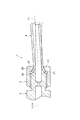
- the fuel distribution device 1 includes a fuel distribution pipe 3 that supplies fuel to a plurality of fuel injection devices 2, a fuel pipe 4 that is connected to the fuel distribution pipe 3, and a connection that connects the fuel distribution pipe 3 and the fuel pipe 4. And a member 5.
- the fuel distribution pipe 3 is also called a fuel injection rail, a fuel delivery pipe, a common rail, or the like.
- the fuel distribution pipe 3 includes a pipe part 11, a plurality of cup parts 12, a lid part 13, a connection part 14, and a fixing boss 15.
- the pipe portion 11 stores the fuel pumped from the high pressure pump in a high pressure state in order to supply the fuel to the plurality of fuel injection devices 2.
- the pipe part 11 is formed in a circular tube extending linearly along the cylinder row direction (crank shaft direction) of the engine.
- the inner peripheral surface of the pipe part 11 forms a fuel flow path.
- a reduced diameter portion 17 having a reduced diameter is formed on the inner peripheral surface of the tube portion 11.
- the reduced diameter portion 17 reduces the fuel pressure fluctuation by narrowing the fuel flow path, and suppresses the pulsation of the fuel from spreading into the pipe portion 11.
- the reduced diameter portion 17 can be, for example, an orifice.
- the tube shape of the tube part 11 does not necessarily need to be a circular tube extending linearly, and can be various shapes.
- the cup portion 12 is provided corresponding to the fuel injection device 2 and supplies the fuel stored in the pipe portion 11 to the fuel injection device 2.
- the cup portion 12 is fixed to the tube portion 11 and holds the fuel injection device 2 so as to be airtight with the fuel injection device 2.
- the lid 13 is located at the end of the pipe 11 opposite to the fuel pipe 4 (left side in FIG. 2) and closes one end of the pipe 11.
- the connecting part 14 is located at the end of the pipe part 11 on the fuel pipe 4 side (right side in FIG. 2) and is connected to the fuel pipe 4.
- the connection portion 14 is formed in a circular tube shape like the tube portion 11, and the inner peripheral surface of the connection portion 14 forms a fuel flow path.
- the connection portion 14 includes a seat portion 21 and a screw portion 22.
- the seat portion 21 is located at the end of the connecting portion 14 on the fuel pipe 4 side (right side in FIG. 2) and is pressed against the fuel pipe 4.
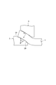
- a first convex curved surface 24 is formed on the outer peripheral surface of the seat portion 21.
- the first convex curved surface 24 is a seating surface against which the fuel pipe 4 is pressed (contacted), and serves as a seal surface that seals the fuel pipe 4.
- the first convex curved surface 24 is reduced in diameter into a convex curved surface toward the tip on the fuel pipe 4 side. That is, the first convex curved surface 24 is formed in a convex curve shape in a cross section passing through the tube axis L 1 of the connecting portion 14. More specifically, the first convex curved surface 24 is formed in a spherical shape having a center point on the tube axis L 1 of the connecting portion 14. That is, the first convex curved surface 24 is formed in an arc shape centered on a point on the tube axis L 1 of the connection portion 14 in a cross section passing through the tube axis L 1 of the connection portion 14.
- the screw portion 22 is positioned on the opposite side (left side in FIG. 2) of the fuel pipe 4 with respect to the seat portion 21 and is fastened to the connecting member 5.
- a male screw 25 for fastening the connecting member 5 is formed on the outer peripheral surface of the screw portion 22.
- the fixing boss 15 is a member for fixing the fuel distribution pipe 3 to the engine.
- the fixing boss 15 can be fixed to the engine by bolting, welding or the like.
- the fuel pipe 4 is a pipe for circulating fuel.
- the fuel pipe 4 can be a pipe for supplying high-pressure fuel compressed by a high-pressure pump to the fuel distribution pipe 3.
- the fuel pipe 4 is a pipe for supplying fuel from one fuel distribution pipe 3 to the other fuel distribution pipe 3. be able to.
- the fuel pipe 4 includes a pipe part 26 and a seal part 27.
- the piping part 26 is a part for circulating fuel.
- the piping part 26 is formed in a substantially tubular shape having the same shape in the longitudinal direction.
- the piping part 26 is suitably bent according to the place arrange
- the seal part 27 seals between the seat part 21 by being pressed by the seat part 21.
- the seal part 27 is located on the fuel distribution pipe 3 side of the pipe part 26 and is located on the end part of the fuel pipe 4 on the fuel distribution pipe 3 side.
- the seal portion 27 is expanded in a funnel shape toward the tip on the fuel distribution pipe 3 side.
- a second concave curved surface 28 is formed on the inner peripheral surface of the seal portion 27, and a second convex curved surface 29 is formed on the outer peripheral surface of the seal portion 27.
- the second concave curved surface 28 is a surface on which the first convex curved surface 24 is pressed (contacted), and serves as a sealing surface that seals with the first convex curved surface 24.
- the second concave curved surface 28 is expanded in a concave curved shape toward the tip on the fuel distribution pipe 3 side. That is, the second concave curved surface 28 is formed in a concave curve shape in a cross section passing through the tube axis L 2 of the seal portion 27.
- the radius of curvature SR 2 of the second concave curved surface 28 is larger than the radius of curvature SR 1 of the first convex curved surface 24.
- the second concave curved surface 28 is formed in an aspherical shape, and a straight line L 3 connecting an arbitrary point P on the second concave curved surface 28 and the center of curvature O 2 of the second concave curved surface 28 at the point P. Passes through the center of curvature O 1 of the first convex curved surface 24. Therefore, the center of curvature O 2 of the second concave curved surface 28 is not a single point, but the position of the center of curvature O 2 varies depending on the position of the point P on the second concave curved surface 28.
- the second convex curved surface 29 is a surface on which the connecting member 5 is pressed (contacted).
- the second convex curved surface 29 has a shape corresponding to the second concave curved surface 28.
- the second convex surface 29 is expanded in a convex curved shape toward the tip of the fuel distribution pipe 3 side, it is formed in a convex curved shape in cross-section through the tube axis L 2 of the sealing portion 27.
- a method for manufacturing the fuel pipe 4 will be described.
- a circular tube A having the same diameter is prepared in the longitudinal direction.
- the processing die B having a processing surface corresponding to the second concave curved surface 28 is pushed into the circular tube A, and the end portion of the circular tube A is expanded.
- the fuel pipe 4 in which the second concave curved surface 28 is formed is obtained.
- the second concave curved surface 28 is formed by pressing the machining surface of the machining die B. For this reason, by reducing the surface roughness of the processed surface of the processing mold B, the surface roughness of the second concave curved surface 28 can be easily reduced.
- the connecting member 5 seals the first convex curved surface 24 and the second concave curved surface 28 by pressing the seal portion 27 against the seat portion 21 from the opposite side of the fuel distribution pipe 3.
- connection member 5 is also called a union nut, a union joint, a joint nut, or the like.
- the connecting member 5 is formed in a cylindrical shape, and the fuel distribution pipe 3 and the fuel pipe 4 are inserted into the space inside the connecting member 5 in the radial direction.
- the central axis L 4 of the connecting member 5 coincides with the pipe axis L 1 of the connecting portion 14 when the fuel distribution pipe 3 and the fuel pipe 4 are connected.
- the connection member 5 includes a locking part 31 and a screwing part 32.
- the locking part 31 is located at the end of the connecting member 5 on the fuel pipe 4 side (right side in FIG. 2) and is locked to the second convex curved surface 29 from the opposite side of the fuel distribution pipe 3.
- a locking inner peripheral surface 34 that is locked to the second convex curved surface 29 from the opposite side of the fuel distribution pipe 3 is formed on the inner peripheral surface of the locking portion 31.
- the locking inner peripheral surface 34 is formed in a conical shape whose diameter decreases toward the tip on the fuel pipe 4 side, and is formed in a straight line in a cross section passing through the central axis L 4 of the connecting member 5.
- the screwing portion 32 is located on the fuel distribution pipe 3 side (left side in FIG. 2) with respect to the locking portion 31 and is screwed to the outer peripheral surface of the fuel distribution pipe 3.
- a female screw 35 that is screwed into a male screw 25 formed on the outer peripheral surface of the screw portion 22 of the connecting portion 14 is engraved.
- the screwing part 32 moves the connecting member 5 to the fuel distribution pipe 3 side by screwing the female screw 35 to the male screw 25.
- the locking inner peripheral surface 34 is locked to the second convex curved surface 29, whereby the connecting member 5 presses the seal portion 27 against the seat portion 21 from the opposite side of the fuel distribution pipe 3.
- this seal surface pressure becomes lower due to initial loosening and loosening with time.
- the initial slack is slack caused by the contact surface (seal surface) of the fuel distribution pipe 3 and the fuel pipe 4 being crushed, deformation of the fuel distribution pipe 3 and the fuel pipe 4 due to axial force, and the like.
- the slack over time is a slack caused by deformation of the fuel distribution pipe 3 and the fuel pipe 4 due to fuel pressure fluctuation.
- FIG. 7 shows that the seal surface pressure required in the initial stage decreases as the surface roughness of the seal surface decreases. In order to suppress the loosening over time, it is effective to adopt a structure in which the pressure fluctuation of the fuel is not received at the connecting portion of the fuel distribution pipe 3 and the fuel pipe 4.
- the seal portion 27 of the fuel pipe 4 is expanded toward the tip on the fuel distribution pipe 3 side, and the first convex curved surface 24 is brought into contact with the inner peripheral surface thereof.
- a second concave curved surface 28 is formed.
- the surface roughness of the second concave curved surface 28 can be easily reduced by strongly pressing the processing mold against the second concave curved surface 28 (see FIG. 3). Thereby, the looseness (initial looseness) of the seal surface pressure associated with the crushing of the second concave curved surface 28 can be suppressed.
- the curvature of the second concave curved surface 28 the radius SR 2 and the curvature radius SR 1 of the first convex surface 24 is considered for the same comparative example.
- this comparative example when axial force is generated in the fuel distribution pipe 3 and the fuel pipe 4 by the connecting member 5, the seal surface pressure generated on the seal surfaces (the first convex curved surface 24 and the second concave curved surface 28) is dispersed. End up. For this reason, in order to generate a high seal surface pressure, it is necessary to tighten the connecting member 5 to generate a large axial force in the fuel distribution pipe 3 and the fuel pipe 4.
- the radius of curvature SR 2 of the second concave curved surface 28 is larger than the radius of curvature SR 1 of the first convex curved surface 24.
- the first convex curved surface 24 and the second concave curved surface 28 come into line contact.
- the connecting member 5 is tightened to generate axial force on the fuel distribution pipe 3 and the fuel pipe 4
- the seal surface pressure generated on the seal surfaces (the first convex curved surface 24 and the second concave curved surface 28) is concentrated.
- the axial force generated by tightening the connecting member 5 can be efficiently converted into the seal surface pressure. That is, a higher seal surface pressure than that of the comparative example can be generated with respect to the axial force generated by the connecting member 5.
- the JIS tolerance grade is practically about 6 to 7 grade.
- the JIS tolerance grade is practically about 10 grade.
- 1.01 times the radius of curvature SR 1 of the curvature radius SR 2 of the second concave curved surface 28 first convex surface 24 ( with 101%) or more, it is possible to increase the curvature radius SR 2 of the second concave curved surface 28 than the radius of curvature SR 1 of the first convex surface 24. Therefore, the curvature radius SR 2 of the second concave curved surface 28 may be 1.01 times the radius of curvature SR 1 of the first convex surface 24 (101%) or more.
- the first convex curved surface 24 and the second concave curved surface 28 are increased until the ratio of the curvature radius SR 2 of the second concave curved surface 28 to the curvature radius SR 1 of the first convex curved surface 24 increases to some extent. Due to the dimensional variation, the seal surface pressure changes greatly. Therefore, the curvature radius SR 2 of the second concave curved surface 28 further, 1.03 times the radius of curvature SR 1 of the first convex surface 24 (103%) or more, more and 1.05 (105%) or more be able to.
- the curvature radius SR 2 of the second concave surface 28 2.00 times the radius of curvature SR 1 of the first convex surface 24 (200%) or less, and further, to 1.50 times (150%) or less Can do.
- the first convex curved surface 24 is formed into a spherical shape, and an arbitrary point P on the second concave curved surface 28 and the center of curvature O 2 of the second concave curved surface 28 at the point P.
- a straight line L 3 that connects to the first convex curved surface 24 passes through the center of curvature O 1 . Therefore, (see FIG. 5) the fuel pipe 4 is connected by inclined to the tube axis L 1 of the fuel distribution pipe 3, to hold the sealing state between the first convex surface 24 and the second concave curved surface 28 be able to.
- the locking inner peripheral surface 34 that is locked to the second convex curved surface 29 is formed in a conical shape, the second convex curved surface 29 and the locking inner peripheral surface 34 are in line contact. Thereby, the pressing force of the seal part 27 by the connection member 5 can be efficiently converted into the seal surface pressure.
- the seat portion 21 is described as being integral with the screw portion 22, but the seat portion 21A may be separate from the screw portion 22A as in the fuel distributor 1A shown in FIG. Good.
- the seat portion 21A is an independent member although it is a member constituting the fuel distribution pipe.
- the outer peripheral surface of the seat portion 21A is in contact with the first seal surface 211A that is in contact with the seat surface 23A formed on the inner peripheral surface of the screw portion 22A, and the second concave curved surface 28 of the seal portion 27. 212A of 2nd sealing surfaces are formed.
- the seat surface 23A is located on the inner peripheral surface, it is possible to prevent the seat surface 23A from being damaged when the fuel distribution pipe 3 is transported.
Landscapes
- Engineering & Computer Science (AREA)
- General Engineering & Computer Science (AREA)
- Mechanical Engineering (AREA)
- Chemical & Material Sciences (AREA)
- Combustion & Propulsion (AREA)
- Fuel-Injection Apparatus (AREA)
- Joints With Pressure Members (AREA)
Abstract
L'invention concerne un dispositif (1) de distribution de carburant comprenant : un tuyau de distribution de carburant (3) qui distribue et fournit du carburant à une pluralité de dispositifs (2) d'injection de carburant ; une tuyauterie de carburant (4) reliée au tuyau de distribution de carburant (3) ; et un élément (5) de liaison qui relie le tuyau de distribution de carburant (3) et la tuyauterie de carburant (4). Le tuyau de distribution de carburant (3) comprend une section siège (21), sur la surface périphérique externe de laquelle est formée une première surface incurvée de manière convexe (24) dont le diamètre diminue selon une forme de surface incurvée de manière convexe vers la pointe côté tuyauterie de carburant (4). La tuyauterie de carburant (4) comprend une section d'étanchéité (27), sur la surface périphérique interne de laquelle est formée une seconde surface incurvée de manière concave (28) dont le diamètre augmente selon une forme de surface incurvée de manière concave vers la pointe sur le tuyau de distribution de carburant (3) et avec laquelle la première surface incurvée de manière convexe (24) est en contact et à la surface périphérique externe de laquelle est formée une seconde surface incurvée de manière convexe (29) correspondant à la seconde surface incurvée de manière concave (28). L'élément de liaison (5) presse une section d'étanchéité (27) contre la section siège (21) en regard du tuyau de distribution de carburant (3). Le rayon de courbure SR2 de la seconde surface (28) incurvée de manière concave est supérieur au rayon de courbure SR1 de la première surface (24) incurvée de manière convexe 24.
Priority Applications (3)
| Application Number | Priority Date | Filing Date | Title |
|---|---|---|---|
| CN201780030110.4A CN109154263B (zh) | 2016-05-19 | 2017-01-18 | 燃料分配装置 |
| DE112017002558.3T DE112017002558T5 (de) | 2016-05-19 | 2017-01-18 | Kraftstoff-Verteilungsvorrichtung |
| US16/302,515 US11022082B2 (en) | 2016-05-19 | 2017-01-18 | Fuel distribution device |
Applications Claiming Priority (2)
| Application Number | Priority Date | Filing Date | Title |
|---|---|---|---|
| JP2016-100604 | 2016-05-19 | ||
| JP2016100604A JP6730089B2 (ja) | 2016-05-19 | 2016-05-19 | 燃料分配装置 |
Publications (1)
| Publication Number | Publication Date |
|---|---|
| WO2017199466A1 true WO2017199466A1 (fr) | 2017-11-23 |
Family
ID=60325791
Family Applications (1)
| Application Number | Title | Priority Date | Filing Date |
|---|---|---|---|
| PCT/JP2017/001540 Ceased WO2017199466A1 (fr) | 2016-05-19 | 2017-01-18 | Dispositif de distribution de carburant |
Country Status (5)
| Country | Link |
|---|---|
| US (1) | US11022082B2 (fr) |
| JP (1) | JP6730089B2 (fr) |
| CN (1) | CN109154263B (fr) |
| DE (1) | DE112017002558T5 (fr) |
| WO (1) | WO2017199466A1 (fr) |
Families Citing this family (2)
| Publication number | Priority date | Publication date | Assignee | Title |
|---|---|---|---|---|
| JP6734179B2 (ja) * | 2016-10-31 | 2020-08-05 | 三桜工業株式会社 | 燃料配管 |
| KR102258649B1 (ko) * | 2019-12-24 | 2021-06-01 | 주식회사 현대케피코 | 연료 레일 |
Citations (11)
| Publication number | Priority date | Publication date | Assignee | Title |
|---|---|---|---|---|
| US1326970A (en) * | 1917-03-14 | 1920-01-06 | American Marine Equipment Corp | Coupling and the like |
| US1977241A (en) * | 1933-04-29 | 1934-10-16 | Arthur L Parker | Tube coupling |
| JPH03209093A (ja) * | 1989-10-14 | 1991-09-12 | Usui Internatl Ind Co Ltd | 高圧燃料レールにおける分岐枝管の接続構造 |
| JPH0875075A (ja) * | 1994-06-28 | 1996-03-19 | Usui Internatl Ind Co Ltd | 高圧燃料レールにおける分岐接続体の接続構造 |
| JP2002039456A (ja) * | 2000-07-28 | 2002-02-06 | Yanagisawa Seiki Mfg Co Ltd | 継手部材 |
| US20030047945A1 (en) * | 2001-09-11 | 2003-03-13 | Schroeder Fred Georg | Flare fitting assembly with metal-to-metal line seal |
| WO2003078827A1 (fr) * | 2002-03-15 | 2003-09-25 | Renault S.A.S. | Dispositif de montage d'un tuyau pression et une rampe commune d'alimentation en carburant |
| DE102004053658A1 (de) * | 2004-11-03 | 2006-05-04 | Benteler Automobiltechnik Gmbh | Verbindungsanordnung |
| JP2006194233A (ja) * | 2004-06-17 | 2006-07-27 | Usui Kokusai Sangyo Kaisha Ltd | 内燃機関用燃料レールにおける分岐枝管の継手構造と分岐枝管およびその分岐枝管の製造方法 |
| JP2009299717A (ja) * | 2008-06-10 | 2009-12-24 | Advics Co Ltd | 管継手 |
| US20100301601A1 (en) * | 2009-06-01 | 2010-12-02 | Hitachi Automotive Products (Usa), Inc. | Fluid coupling for a direct injection engine |
Family Cites Families (7)
| Publication number | Priority date | Publication date | Assignee | Title |
|---|---|---|---|---|
| JP2898384B2 (ja) * | 1989-09-27 | 1999-05-31 | 臼井国際産業株式会社 | 高圧燃料レールにおける分岐接続体の接続構造 |
| JP2915099B2 (ja) * | 1990-06-30 | 1999-07-05 | 臼井国際産業株式会社 | 高圧燃料多岐管における分岐接続体の接続構造 |
| US5667255A (en) * | 1994-06-28 | 1997-09-16 | Usui Kokusai Sangyo Kaisha Ltd. | Joint structure for joining a branch member to a high pressure fuel rail |
| KR100999025B1 (ko) * | 2006-03-14 | 2010-12-09 | 우수이 고쿠사이 산교 가부시키가이샤 | 고압 연료 분사관의 접속 헤드부 구조 |
| DE102010064115A1 (de) | 2010-12-23 | 2012-06-28 | Robert Bosch Gmbh | Injektoranordnung, die vorzugsweise für Erdgas dient |
| JP2013199884A (ja) | 2012-03-26 | 2013-10-03 | Otics Corp | 燃料分配管 |
| DE102012206887A1 (de) | 2012-04-26 | 2013-10-31 | Robert Bosch Gmbh | Anordnung mit einem Brennstoffverteiler und mehreren Brennstoffeinspritzventilen |
-
2016
- 2016-05-19 JP JP2016100604A patent/JP6730089B2/ja active Active
-
2017
- 2017-01-18 US US16/302,515 patent/US11022082B2/en active Active
- 2017-01-18 WO PCT/JP2017/001540 patent/WO2017199466A1/fr not_active Ceased
- 2017-01-18 DE DE112017002558.3T patent/DE112017002558T5/de active Pending
- 2017-01-18 CN CN201780030110.4A patent/CN109154263B/zh active Active
Patent Citations (11)
| Publication number | Priority date | Publication date | Assignee | Title |
|---|---|---|---|---|
| US1326970A (en) * | 1917-03-14 | 1920-01-06 | American Marine Equipment Corp | Coupling and the like |
| US1977241A (en) * | 1933-04-29 | 1934-10-16 | Arthur L Parker | Tube coupling |
| JPH03209093A (ja) * | 1989-10-14 | 1991-09-12 | Usui Internatl Ind Co Ltd | 高圧燃料レールにおける分岐枝管の接続構造 |
| JPH0875075A (ja) * | 1994-06-28 | 1996-03-19 | Usui Internatl Ind Co Ltd | 高圧燃料レールにおける分岐接続体の接続構造 |
| JP2002039456A (ja) * | 2000-07-28 | 2002-02-06 | Yanagisawa Seiki Mfg Co Ltd | 継手部材 |
| US20030047945A1 (en) * | 2001-09-11 | 2003-03-13 | Schroeder Fred Georg | Flare fitting assembly with metal-to-metal line seal |
| WO2003078827A1 (fr) * | 2002-03-15 | 2003-09-25 | Renault S.A.S. | Dispositif de montage d'un tuyau pression et une rampe commune d'alimentation en carburant |
| JP2006194233A (ja) * | 2004-06-17 | 2006-07-27 | Usui Kokusai Sangyo Kaisha Ltd | 内燃機関用燃料レールにおける分岐枝管の継手構造と分岐枝管およびその分岐枝管の製造方法 |
| DE102004053658A1 (de) * | 2004-11-03 | 2006-05-04 | Benteler Automobiltechnik Gmbh | Verbindungsanordnung |
| JP2009299717A (ja) * | 2008-06-10 | 2009-12-24 | Advics Co Ltd | 管継手 |
| US20100301601A1 (en) * | 2009-06-01 | 2010-12-02 | Hitachi Automotive Products (Usa), Inc. | Fluid coupling for a direct injection engine |
Also Published As
| Publication number | Publication date |
|---|---|
| JP6730089B2 (ja) | 2020-07-29 |
| US11022082B2 (en) | 2021-06-01 |
| DE112017002558T5 (de) | 2019-02-28 |
| US20190293214A1 (en) | 2019-09-26 |
| CN109154263A (zh) | 2019-01-04 |
| CN109154263B (zh) | 2021-08-10 |
| JP2017207018A (ja) | 2017-11-24 |
Similar Documents
| Publication | Publication Date | Title |
|---|---|---|
| EP0002384B1 (fr) | Conduit pour fluide sous pression | |
| US20160131285A1 (en) | Piping joint structure | |
| US8783731B2 (en) | Connecting arrangement | |
| US10352485B2 (en) | Pipe connecting device | |
| CN102341634A (zh) | 管连接器 | |
| JP6649677B2 (ja) | ガソリン直噴エンジン用燃料レール | |
| KR20080092933A (ko) | 파이프 연결 장치 | |
| WO2017199466A1 (fr) | Dispositif de distribution de carburant | |
| US20180094614A1 (en) | Fuel pipe connecting head and fuel pipe | |
| KR20170031785A (ko) | 가솔린 직접 분사 엔진용 연료 레일의 단말 시일 구조 | |
| KR20170024091A (ko) | 가솔린 직분사 엔진용 연료 레일의 단말 시일 구조 | |
| EP3533991B1 (fr) | Conduite d'alimentation en carburant | |
| JP2010216431A (ja) | コモンレール | |
| KR101960201B1 (ko) | 가솔린 직분사 엔진용 연료 레일의 단말 시일 구조 | |
| KR20210104894A (ko) | 조인트 구조체 | |
| GB2550611A (en) | Common rail | |
| KR101709723B1 (ko) | 파이프 연결구 | |
| JP2011256945A (ja) | 拡管式管継手 | |
| KR102050044B1 (ko) | 고압밸브용 풀림방지장치 | |
| US20100301601A1 (en) | Fluid coupling for a direct injection engine | |
| KR20220059412A (ko) | 관 이음매 구조 | |
| KR20170100966A (ko) | 파이프와 파이프의 연결구조 | |
| JP2007292215A (ja) | 管接続具 |
Legal Events
| Date | Code | Title | Description |
|---|---|---|---|
| 121 | Ep: the epo has been informed by wipo that ep was designated in this application |
Ref document number: 17798905 Country of ref document: EP Kind code of ref document: A1 |
|
| 122 | Ep: pct application non-entry in european phase |
Ref document number: 17798905 Country of ref document: EP Kind code of ref document: A1 |