WO2017199466A1 - 燃料分配装置 - Google Patents
燃料分配装置 Download PDFInfo
- Publication number
- WO2017199466A1 WO2017199466A1 PCT/JP2017/001540 JP2017001540W WO2017199466A1 WO 2017199466 A1 WO2017199466 A1 WO 2017199466A1 JP 2017001540 W JP2017001540 W JP 2017001540W WO 2017199466 A1 WO2017199466 A1 WO 2017199466A1
- Authority
- WO
- WIPO (PCT)
- Prior art keywords
- fuel
- curved surface
- fuel distribution
- pipe
- distribution pipe
- Prior art date
- Legal status (The legal status is an assumption and is not a legal conclusion. Google has not performed a legal analysis and makes no representation as to the accuracy of the status listed.)
- Ceased
Links
Images


Classifications
-
- F—MECHANICAL ENGINEERING; LIGHTING; HEATING; WEAPONS; BLASTING
- F02—COMBUSTION ENGINES; HOT-GAS OR COMBUSTION-PRODUCT ENGINE PLANTS
- F02M—SUPPLYING COMBUSTION ENGINES IN GENERAL WITH COMBUSTIBLE MIXTURES OR CONSTITUENTS THEREOF
- F02M55/00—Fuel-injection apparatus characterised by their fuel conduits or their venting means; Arrangements of conduits between fuel tank and pump F02M37/00
- F02M55/004—Joints; Sealings
- F02M55/005—Joints; Sealings for high pressure conduits, e.g. connected to pump outlet or to injector inlet
-
- F—MECHANICAL ENGINEERING; LIGHTING; HEATING; WEAPONS; BLASTING
- F02—COMBUSTION ENGINES; HOT-GAS OR COMBUSTION-PRODUCT ENGINE PLANTS
- F02M—SUPPLYING COMBUSTION ENGINES IN GENERAL WITH COMBUSTIBLE MIXTURES OR CONSTITUENTS THEREOF
- F02M55/00—Fuel-injection apparatus characterised by their fuel conduits or their venting means; Arrangements of conduits between fuel tank and pump F02M37/00
- F02M55/004—Joints; Sealings
-
- F—MECHANICAL ENGINEERING; LIGHTING; HEATING; WEAPONS; BLASTING
- F02—COMBUSTION ENGINES; HOT-GAS OR COMBUSTION-PRODUCT ENGINE PLANTS
- F02M—SUPPLYING COMBUSTION ENGINES IN GENERAL WITH COMBUSTIBLE MIXTURES OR CONSTITUENTS THEREOF
- F02M55/00—Fuel-injection apparatus characterised by their fuel conduits or their venting means; Arrangements of conduits between fuel tank and pump F02M37/00
- F02M55/02—Conduits between injection pumps and injectors, e.g. conduits between pump and common-rail or conduits between common-rail and injectors
- F02M55/025—Common rails
-
- F—MECHANICAL ENGINEERING; LIGHTING; HEATING; WEAPONS; BLASTING
- F02—COMBUSTION ENGINES; HOT-GAS OR COMBUSTION-PRODUCT ENGINE PLANTS
- F02M—SUPPLYING COMBUSTION ENGINES IN GENERAL WITH COMBUSTIBLE MIXTURES OR CONSTITUENTS THEREOF
- F02M61/00—Fuel-injectors not provided for in groups F02M39/00 - F02M57/00 or F02M67/00
- F02M61/14—Arrangements of injectors with respect to engines; Mounting of injectors
-
- F—MECHANICAL ENGINEERING; LIGHTING; HEATING; WEAPONS; BLASTING
- F02—COMBUSTION ENGINES; HOT-GAS OR COMBUSTION-PRODUCT ENGINE PLANTS
- F02M—SUPPLYING COMBUSTION ENGINES IN GENERAL WITH COMBUSTIBLE MIXTURES OR CONSTITUENTS THEREOF
- F02M69/00—Low-pressure fuel-injection apparatus ; Apparatus with both continuous and intermittent injection; Apparatus injecting different types of fuel
- F02M69/46—Details, component parts or accessories not provided for in, or of interest apart from, the apparatus covered by groups F02M69/02 - F02M69/44
- F02M69/462—Arrangement of fuel conduits, e.g. with valves for maintaining pressure in the pipes after the engine being shut-down
- F02M69/465—Arrangement of fuel conduits, e.g. with valves for maintaining pressure in the pipes after the engine being shut-down of fuel rails
-
- F—MECHANICAL ENGINEERING; LIGHTING; HEATING; WEAPONS; BLASTING
- F16—ENGINEERING ELEMENTS AND UNITS; GENERAL MEASURES FOR PRODUCING AND MAINTAINING EFFECTIVE FUNCTIONING OF MACHINES OR INSTALLATIONS; THERMAL INSULATION IN GENERAL
- F16L—PIPES; JOINTS OR FITTINGS FOR PIPES; SUPPORTS FOR PIPES, CABLES OR PROTECTIVE TUBING; MEANS FOR THERMAL INSULATION IN GENERAL
- F16L19/00—Joints in which sealing surfaces are pressed together by means of a member, e.g. a swivel nut, screwed on, or into, one of the joint parts
- F16L19/04—Joints in which sealing surfaces are pressed together by means of a member, e.g. a swivel nut, screwed on, or into, one of the joint parts using additional rigid rings, sealing directly on at least one pipe end, which is flared either before or during the making of the connection
- F16L19/05—Joints in which sealing surfaces are pressed together by means of a member, e.g. a swivel nut, screwed on, or into, one of the joint parts using additional rigid rings, sealing directly on at least one pipe end, which is flared either before or during the making of the connection with a rigid pressure ring between the screwed member and the exterior of the flared pipe end
Definitions
- the present invention relates to a fuel distribution device that distributes and supplies fuel to a plurality of fuel injection devices.
- a fuel distribution device used for a direct injection engine or the like includes a fuel distribution pipe that distributes high-pressure fuel compressed by a high-pressure pump to a plurality of fuel injection devices, a fuel pipe connected to the fuel distribution pipe, A connecting member for connecting the pipe and the fuel pipe.
- Patent Document 1 In the fuel distribution device described in Patent Document 1, the fuel pipe is provided with a tip (13) extending in a funnel shape. Then, by tightening the screw portion (10) of the connecting member to the outer peripheral surface of the fuel distribution pipe, the seal surface (15) of the fuel pipe is pressed against the seal seat surface (16) of the fuel distribution pipe, and the seal surface (15 ) And the seal seat surface (16). Patent Document 1 describes a conical shape and a spherical shape corresponding to the seal seat surface (16) as the shape of the seal surface (15).
- the seal surface (15) of the fuel pipe has a conical shape or a spherical shape corresponding to the seal seat surface (16).
- the sealing surface (15) is conical, when the fuel pipe is inclined with respect to the axis of the fuel distribution pipe, the sealing surface pressure changes depending on the location. For this reason, a sealing surface (15) and a seal seat surface (16) cannot be sealed stably.
- the seal surface pressure is dispersed because the seal surface (15) and the seal seat surface (16) are in surface contact. The fastening force (axial force) of the connecting member cannot be efficiently converted into the seal surface pressure. For this reason, the seal surface pressure between the seal surface (15) and the seal seat surface (16) becomes small, and the seal surface (15) and the seal seat surface (16) cannot be stably sealed.
- an object of the present invention is to provide a fuel distributor that can stably seal a fuel distribution pipe and a fuel pipe.
- a fuel distribution device includes a fuel distribution pipe that distributes fuel to a plurality of fuel injection devices, a fuel pipe connected to the fuel distribution pipe, and a connection that connects the fuel distribution pipe and the fuel pipe.
- the fuel distribution pipe has a seat portion formed with a first convex curved surface whose diameter is reduced to a convex curved shape toward the tip on the fuel pipe side on the outer peripheral surface;
- the fuel pipe is formed with a second concave curved surface whose diameter increases toward the tip on the fuel distribution pipe side on the inner peripheral surface so that the first convex curved surface is in contact with the second concave curved surface on the outer peripheral surface.
- the seal member has a second convex curved surface corresponding to the curved surface, the connecting member presses the seal portion against the seat from the opposite side of the fuel distribution pipe, and the radius of curvature of the second concave curved surface is the first convex It is larger than the radius of curvature of the curved surface.
- the connecting member presses the seal portion against the seat from the opposite side of the fuel distribution pipe, and the first convex curved surface of the fuel distribution pipe and the second concave curved surface of the fuel pipe Is sealed.
- the seal portion of the fuel pipe is expanded toward the tip on the fuel distribution pipe side, and a second concave curved surface with which the first convex curved surface abuts is formed on the inner peripheral surface thereof.
- the surface roughness (surface roughness) of the second concave curved surface can be easily reduced by strongly pressing the processing mold against the second concave curved surface.
- the seal portion even if the connection member presses the seal portion against the seat from the opposite side of the fuel distribution pipe, the seal portion only has a state where the tube wall is sandwiched between the connection member and the seat. For this reason, even if the pressing force by the connecting member is increased in order to increase the seal surface pressure, the seal portion is not easily deformed. Further, since the seal portion is hardly affected by the fuel pressure fluctuation, the seal portion is not easily deformed by the fuel pressure fluctuation. Thereby, loosening of the seal surface pressure accompanying deformation of the seal portion can be suppressed.
- the fuel pipe can be inclined with respect to the axis of the fuel distribution pipe to connect the fuel distribution pipe and the fuel pipe. it can.
- the curvature radius of a 2nd concave curved surface is larger than the curvature radius of a 1st convex curved surface, when a sealing part is pressed against a seat part by a connection member, a 1st convex curved surface and a 2nd concave curved surface will line-contact.
- the seal surface pressure of the 1st convex curved surface and the 2nd concave curved surface concentrates, the pressing force of the seal part by a connection member can be efficiently converted into a seal surface pressure.
- the fuel distribution pipe and the fuel pipe can be stably sealed.
- the first convex curved surface is formed in a spherical shape, and a straight line connecting the point on the second concave curved surface and the center of curvature of the second concave curved surface at the point is the first convex curved surface. You may pass through the center of curvature.
- the first convex curved surface is formed into a spherical shape, and the straight line connecting the point on the second concave curved surface and the center of curvature of the second concave curved surface at the point is the center of curvature of the first convex curved surface. Pass through. For this reason, even if the fuel pipe is inclined and connected to the axis of the fuel distribution pipe, the seal state between the first convex curved surface and the second concave curved surface can be maintained.
- the connecting member is screwed into the locking inner peripheral surface locked to the second convex curved surface from the opposite side of the fuel distribution pipe, and the outer peripheral surface of the fuel distribution pipe.
- a locking inner peripheral surface may be formed in a conical shape.
- the locking inner peripheral surface locks the second concave curved surface from the opposite side of the fuel distribution pipe. For this reason, the seal portion can be pressed against the seat portion from the opposite side of the fuel distribution pipe by screwing the screw engagement section with the outer peripheral surface of the fuel distribution pipe and moving the connecting member to the fuel distribution pipe side.
- the latching inner peripheral surface latched by the 2nd convex curved surface is formed in cone shape, the 2nd convex curved surface and the latching inner peripheral surface are in line contact. Thereby, the pressing force of the seal part by the connecting member can be efficiently converted into the seal surface pressure between the first convex curved surface and the second concave curved surface.
- the fuel distribution pipe and the fuel pipe can be stably sealed.
- the fuel distribution device 1 is a fuel injection device provided with high-pressure fuel compressed by a high-pressure pump (not shown) corresponding to each cylinder of an engine (not shown). 2 is distributed and supplied.
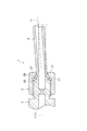
- the fuel distribution device 1 includes a fuel distribution pipe 3 that supplies fuel to a plurality of fuel injection devices 2, a fuel pipe 4 that is connected to the fuel distribution pipe 3, and a connection that connects the fuel distribution pipe 3 and the fuel pipe 4. And a member 5.
- the fuel distribution pipe 3 is also called a fuel injection rail, a fuel delivery pipe, a common rail, or the like.
- the fuel distribution pipe 3 includes a pipe part 11, a plurality of cup parts 12, a lid part 13, a connection part 14, and a fixing boss 15.
- the pipe portion 11 stores the fuel pumped from the high pressure pump in a high pressure state in order to supply the fuel to the plurality of fuel injection devices 2.
- the pipe part 11 is formed in a circular tube extending linearly along the cylinder row direction (crank shaft direction) of the engine.
- the inner peripheral surface of the pipe part 11 forms a fuel flow path.
- a reduced diameter portion 17 having a reduced diameter is formed on the inner peripheral surface of the tube portion 11.
- the reduced diameter portion 17 reduces the fuel pressure fluctuation by narrowing the fuel flow path, and suppresses the pulsation of the fuel from spreading into the pipe portion 11.
- the reduced diameter portion 17 can be, for example, an orifice.
- the tube shape of the tube part 11 does not necessarily need to be a circular tube extending linearly, and can be various shapes.
- the cup portion 12 is provided corresponding to the fuel injection device 2 and supplies the fuel stored in the pipe portion 11 to the fuel injection device 2.
- the cup portion 12 is fixed to the tube portion 11 and holds the fuel injection device 2 so as to be airtight with the fuel injection device 2.
- the lid 13 is located at the end of the pipe 11 opposite to the fuel pipe 4 (left side in FIG. 2) and closes one end of the pipe 11.
- the connecting part 14 is located at the end of the pipe part 11 on the fuel pipe 4 side (right side in FIG. 2) and is connected to the fuel pipe 4.
- the connection portion 14 is formed in a circular tube shape like the tube portion 11, and the inner peripheral surface of the connection portion 14 forms a fuel flow path.
- the connection portion 14 includes a seat portion 21 and a screw portion 22.
- the seat portion 21 is located at the end of the connecting portion 14 on the fuel pipe 4 side (right side in FIG. 2) and is pressed against the fuel pipe 4.
- a first convex curved surface 24 is formed on the outer peripheral surface of the seat portion 21.
- the first convex curved surface 24 is a seating surface against which the fuel pipe 4 is pressed (contacted), and serves as a seal surface that seals the fuel pipe 4.
- the first convex curved surface 24 is reduced in diameter into a convex curved surface toward the tip on the fuel pipe 4 side. That is, the first convex curved surface 24 is formed in a convex curve shape in a cross section passing through the tube axis L 1 of the connecting portion 14. More specifically, the first convex curved surface 24 is formed in a spherical shape having a center point on the tube axis L 1 of the connecting portion 14. That is, the first convex curved surface 24 is formed in an arc shape centered on a point on the tube axis L 1 of the connection portion 14 in a cross section passing through the tube axis L 1 of the connection portion 14.
- the screw portion 22 is positioned on the opposite side (left side in FIG. 2) of the fuel pipe 4 with respect to the seat portion 21 and is fastened to the connecting member 5.
- a male screw 25 for fastening the connecting member 5 is formed on the outer peripheral surface of the screw portion 22.
- the fixing boss 15 is a member for fixing the fuel distribution pipe 3 to the engine.
- the fixing boss 15 can be fixed to the engine by bolting, welding or the like.
- the fuel pipe 4 is a pipe for circulating fuel.
- the fuel pipe 4 can be a pipe for supplying high-pressure fuel compressed by a high-pressure pump to the fuel distribution pipe 3.
- the fuel pipe 4 is a pipe for supplying fuel from one fuel distribution pipe 3 to the other fuel distribution pipe 3. be able to.
- the fuel pipe 4 includes a pipe part 26 and a seal part 27.
- the piping part 26 is a part for circulating fuel.
- the piping part 26 is formed in a substantially tubular shape having the same shape in the longitudinal direction.
- the piping part 26 is suitably bent according to the place arrange
- the seal part 27 seals between the seat part 21 by being pressed by the seat part 21.
- the seal part 27 is located on the fuel distribution pipe 3 side of the pipe part 26 and is located on the end part of the fuel pipe 4 on the fuel distribution pipe 3 side.
- the seal portion 27 is expanded in a funnel shape toward the tip on the fuel distribution pipe 3 side.
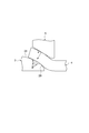
- a second concave curved surface 28 is formed on the inner peripheral surface of the seal portion 27, and a second convex curved surface 29 is formed on the outer peripheral surface of the seal portion 27.
- the second concave curved surface 28 is a surface on which the first convex curved surface 24 is pressed (contacted), and serves as a sealing surface that seals with the first convex curved surface 24.
- the second concave curved surface 28 is expanded in a concave curved shape toward the tip on the fuel distribution pipe 3 side. That is, the second concave curved surface 28 is formed in a concave curve shape in a cross section passing through the tube axis L 2 of the seal portion 27.
- the radius of curvature SR 2 of the second concave curved surface 28 is larger than the radius of curvature SR 1 of the first convex curved surface 24.
- the second concave curved surface 28 is formed in an aspherical shape, and a straight line L 3 connecting an arbitrary point P on the second concave curved surface 28 and the center of curvature O 2 of the second concave curved surface 28 at the point P. Passes through the center of curvature O 1 of the first convex curved surface 24. Therefore, the center of curvature O 2 of the second concave curved surface 28 is not a single point, but the position of the center of curvature O 2 varies depending on the position of the point P on the second concave curved surface 28.
- the second convex curved surface 29 is a surface on which the connecting member 5 is pressed (contacted).
- the second convex curved surface 29 has a shape corresponding to the second concave curved surface 28.
- the second convex surface 29 is expanded in a convex curved shape toward the tip of the fuel distribution pipe 3 side, it is formed in a convex curved shape in cross-section through the tube axis L 2 of the sealing portion 27.
- a method for manufacturing the fuel pipe 4 will be described.
- a circular tube A having the same diameter is prepared in the longitudinal direction.
- the processing die B having a processing surface corresponding to the second concave curved surface 28 is pushed into the circular tube A, and the end portion of the circular tube A is expanded.
- the fuel pipe 4 in which the second concave curved surface 28 is formed is obtained.
- the second concave curved surface 28 is formed by pressing the machining surface of the machining die B. For this reason, by reducing the surface roughness of the processed surface of the processing mold B, the surface roughness of the second concave curved surface 28 can be easily reduced.
- the connecting member 5 seals the first convex curved surface 24 and the second concave curved surface 28 by pressing the seal portion 27 against the seat portion 21 from the opposite side of the fuel distribution pipe 3.
- connection member 5 is also called a union nut, a union joint, a joint nut, or the like.
- the connecting member 5 is formed in a cylindrical shape, and the fuel distribution pipe 3 and the fuel pipe 4 are inserted into the space inside the connecting member 5 in the radial direction.
- the central axis L 4 of the connecting member 5 coincides with the pipe axis L 1 of the connecting portion 14 when the fuel distribution pipe 3 and the fuel pipe 4 are connected.
- the connection member 5 includes a locking part 31 and a screwing part 32.
- the locking part 31 is located at the end of the connecting member 5 on the fuel pipe 4 side (right side in FIG. 2) and is locked to the second convex curved surface 29 from the opposite side of the fuel distribution pipe 3.
- a locking inner peripheral surface 34 that is locked to the second convex curved surface 29 from the opposite side of the fuel distribution pipe 3 is formed on the inner peripheral surface of the locking portion 31.
- the locking inner peripheral surface 34 is formed in a conical shape whose diameter decreases toward the tip on the fuel pipe 4 side, and is formed in a straight line in a cross section passing through the central axis L 4 of the connecting member 5.
- the screwing portion 32 is located on the fuel distribution pipe 3 side (left side in FIG. 2) with respect to the locking portion 31 and is screwed to the outer peripheral surface of the fuel distribution pipe 3.
- a female screw 35 that is screwed into a male screw 25 formed on the outer peripheral surface of the screw portion 22 of the connecting portion 14 is engraved.
- the screwing part 32 moves the connecting member 5 to the fuel distribution pipe 3 side by screwing the female screw 35 to the male screw 25.
- the locking inner peripheral surface 34 is locked to the second convex curved surface 29, whereby the connecting member 5 presses the seal portion 27 against the seat portion 21 from the opposite side of the fuel distribution pipe 3.
- this seal surface pressure becomes lower due to initial loosening and loosening with time.
- the initial slack is slack caused by the contact surface (seal surface) of the fuel distribution pipe 3 and the fuel pipe 4 being crushed, deformation of the fuel distribution pipe 3 and the fuel pipe 4 due to axial force, and the like.
- the slack over time is a slack caused by deformation of the fuel distribution pipe 3 and the fuel pipe 4 due to fuel pressure fluctuation.
- FIG. 7 shows that the seal surface pressure required in the initial stage decreases as the surface roughness of the seal surface decreases. In order to suppress the loosening over time, it is effective to adopt a structure in which the pressure fluctuation of the fuel is not received at the connecting portion of the fuel distribution pipe 3 and the fuel pipe 4.
- the seal portion 27 of the fuel pipe 4 is expanded toward the tip on the fuel distribution pipe 3 side, and the first convex curved surface 24 is brought into contact with the inner peripheral surface thereof.
- a second concave curved surface 28 is formed.
- the surface roughness of the second concave curved surface 28 can be easily reduced by strongly pressing the processing mold against the second concave curved surface 28 (see FIG. 3). Thereby, the looseness (initial looseness) of the seal surface pressure associated with the crushing of the second concave curved surface 28 can be suppressed.
- the curvature of the second concave curved surface 28 the radius SR 2 and the curvature radius SR 1 of the first convex surface 24 is considered for the same comparative example.
- this comparative example when axial force is generated in the fuel distribution pipe 3 and the fuel pipe 4 by the connecting member 5, the seal surface pressure generated on the seal surfaces (the first convex curved surface 24 and the second concave curved surface 28) is dispersed. End up. For this reason, in order to generate a high seal surface pressure, it is necessary to tighten the connecting member 5 to generate a large axial force in the fuel distribution pipe 3 and the fuel pipe 4.
- the radius of curvature SR 2 of the second concave curved surface 28 is larger than the radius of curvature SR 1 of the first convex curved surface 24.
- the first convex curved surface 24 and the second concave curved surface 28 come into line contact.
- the connecting member 5 is tightened to generate axial force on the fuel distribution pipe 3 and the fuel pipe 4
- the seal surface pressure generated on the seal surfaces (the first convex curved surface 24 and the second concave curved surface 28) is concentrated.
- the axial force generated by tightening the connecting member 5 can be efficiently converted into the seal surface pressure. That is, a higher seal surface pressure than that of the comparative example can be generated with respect to the axial force generated by the connecting member 5.
- the JIS tolerance grade is practically about 6 to 7 grade.
- the JIS tolerance grade is practically about 10 grade.
- 1.01 times the radius of curvature SR 1 of the curvature radius SR 2 of the second concave curved surface 28 first convex surface 24 ( with 101%) or more, it is possible to increase the curvature radius SR 2 of the second concave curved surface 28 than the radius of curvature SR 1 of the first convex surface 24. Therefore, the curvature radius SR 2 of the second concave curved surface 28 may be 1.01 times the radius of curvature SR 1 of the first convex surface 24 (101%) or more.
- the first convex curved surface 24 and the second concave curved surface 28 are increased until the ratio of the curvature radius SR 2 of the second concave curved surface 28 to the curvature radius SR 1 of the first convex curved surface 24 increases to some extent. Due to the dimensional variation, the seal surface pressure changes greatly. Therefore, the curvature radius SR 2 of the second concave curved surface 28 further, 1.03 times the radius of curvature SR 1 of the first convex surface 24 (103%) or more, more and 1.05 (105%) or more be able to.
- the curvature radius SR 2 of the second concave surface 28 2.00 times the radius of curvature SR 1 of the first convex surface 24 (200%) or less, and further, to 1.50 times (150%) or less Can do.
- the first convex curved surface 24 is formed into a spherical shape, and an arbitrary point P on the second concave curved surface 28 and the center of curvature O 2 of the second concave curved surface 28 at the point P.
- a straight line L 3 that connects to the first convex curved surface 24 passes through the center of curvature O 1 . Therefore, (see FIG. 5) the fuel pipe 4 is connected by inclined to the tube axis L 1 of the fuel distribution pipe 3, to hold the sealing state between the first convex surface 24 and the second concave curved surface 28 be able to.
- the locking inner peripheral surface 34 that is locked to the second convex curved surface 29 is formed in a conical shape, the second convex curved surface 29 and the locking inner peripheral surface 34 are in line contact. Thereby, the pressing force of the seal part 27 by the connection member 5 can be efficiently converted into the seal surface pressure.
- the seat portion 21 is described as being integral with the screw portion 22, but the seat portion 21A may be separate from the screw portion 22A as in the fuel distributor 1A shown in FIG. Good.
- the seat portion 21A is an independent member although it is a member constituting the fuel distribution pipe.
- the outer peripheral surface of the seat portion 21A is in contact with the first seal surface 211A that is in contact with the seat surface 23A formed on the inner peripheral surface of the screw portion 22A, and the second concave curved surface 28 of the seal portion 27. 212A of 2nd sealing surfaces are formed.
- the seat surface 23A is located on the inner peripheral surface, it is possible to prevent the seat surface 23A from being damaged when the fuel distribution pipe 3 is transported.
Landscapes
- Engineering & Computer Science (AREA)
- General Engineering & Computer Science (AREA)
- Mechanical Engineering (AREA)
- Chemical & Material Sciences (AREA)
- Combustion & Propulsion (AREA)
- Fuel-Injection Apparatus (AREA)
- Joints With Pressure Members (AREA)
Abstract
燃料を複数の燃料噴射装置2に分配供給する燃料分配管3と、燃料分配管3に接続される燃料配管4と、燃料分配管3と燃料配管4とを接続する接続部材5と、を備える燃料分配装置1である。燃料分配管3は、外周面に燃料配管4側の先端に向かって凸曲面状に縮径される第一凸曲面24が形成された座部21を有する。燃料配管4は、内周面に燃料分配管3側の先端に向かって凹曲面状に拡径されて第一凸曲面24が当接される第二凹曲面28が形成されるとともに、外周面に第二凹曲面28に対応する第二凸曲面29が形成されたシール部27を有する。接続部材5は、燃料分配管3の反対側からシール部27を座部21に押圧する。第二凹曲面28の曲率半径SR2は、第一凸曲面24の曲率半径SR1よりも大きい。
Description
本発明は、燃料を複数の燃料噴射装置に分配供給する燃料分配装置に関する。
直噴エンジン等に用いられる燃料分配装置は、高圧ポンプにより圧縮された高圧の燃料を複数の燃料噴射装置に分配供給する燃料分配管と、この燃料分配管に接続された燃料配管と、燃料分配管と前記燃料配管とを接続する接続部材と、を備える。
特許文献1に記載された燃料分配装置では、燃料配管に、漏斗状に広がる先端部(13)が設けられている。そして、接続部材のネジ部(10)を燃料分配管の外周面に締め付けることで、燃料配管のシール面(15)を燃料分配管のシール座面(16)に押圧して、シール面(15)とシール座面(16)とをシールしている。また、特許文献1には、シール面(15)の形状として、円錐状と、シール座面(16)に対応した球面状と、が記載されている。
近年、より高い燃料圧力が必要になってきている。燃料圧力を高くするためには、燃料分配管と燃料配管とのシール面に高い面圧が必要となる。このシール面圧は、燃料分配管に対する燃料配管の締め付けにより発生する軸力と、燃料分配管と燃料配管との接触面積と、により決まる。
しかしながら、特許文献1に記載された燃料分配装置では、燃料配管のシール面(15)は、円錐状、又は、シール座面(16)に対応した球面状である。シール面(15)が円錐状である場合、燃料分配管の軸線に対して燃料配管を傾斜させると、場所によってシール面圧が変わる。このため、シール面(15)とシール座面(16)とを安定的にシールすることができない。また、シール面(15)がシール座面(16)に対応した球面状である場合、シール面(15)とシール座面(16)とが面接触するため、シール面圧が分散してしまい、接続部材の締め付け力(軸力)を効率的にシール面圧に変換することができない。このため、シール面(15)とシール座面(16)とのシール面圧が小さくなって、シール面(15)とシール座面(16)とを安定的にシールすることができない。
そこで、本発明は、燃料分配管と燃料配管とを安定的にシールすることができる燃料分配装置を提供することを目的とする。
本発明の一側面に係る燃料分配装置は、燃料を複数の燃料噴射装置に分配供給する燃料分配管と、燃料分配管に接続される燃料配管と、燃料分配管と燃料配管とを接続する接続部材と、を備える燃料分配装置であって、燃料分配管は、外周面に燃料配管側の先端に向かって凸曲面状に縮径される第一凸曲面が形成された座部を有し、燃料配管は、内周面に燃料分配管側の先端に向かって凹曲面状に拡径されて第一凸曲面が当接される第二凹曲面が形成されるとともに、外周面に第二凹曲面に対応する第二凸曲面が形成されたシール部を有し、接続部材は、燃料分配管の反対側からシール部を座部に押圧し、第二凹曲面の曲率半径は、第一凸曲面の曲率半径よりも大きい。
本発明の一側面に係る燃料分配装置では、接続部材が燃料分配管の反対側からシール部を座部に押圧することで、燃料分配管の第一凸曲面と燃料配管の第二凹曲面とがシールされる。そして、燃料配管のシール部が、燃料分配管側の先端に向かって拡管されており、その内周面に、第一凸曲面が当接される第二凹曲面が形成されている。このため、例えば、第二凹曲面に加工金型を強く押し当てることで、第二凹曲面の面粗度(表面粗さ)を容易に小さくすることができる。これにより、第二凹曲面の潰れに伴う第一凸曲面及び第二凹曲面におけるシール面圧の緩みを抑制することができる。また、接続部材は、燃料分配管の反対側からシール部を座部に押圧しても、シール部は、管壁が接続部材と座部とに挟まれた状態になるだけである。このため、シール面圧を高めるために接続部材による押圧力を大きくしても、シール部は変形しにくい。また、シール部は、燃料の圧力変動の影響をほとんど受けないため、燃料の圧力変動によっても、シール部は変形しにくい。これにより、シール部の変形に伴うシール面圧の緩みを抑制することができる。更に、接続部材と座部とに挟まれるシール部が曲面状に形成されているため、燃料分配管の軸線に対して燃料配管を傾斜させて、燃料分配管と燃料配管とを接続することができる。そして、第二凹曲面の曲率半径が第一凸曲面の曲率半径よりも大きいため、接続部材によりシール部を座部に押圧すると、第一凸曲面と第二凹曲面とは線接触する。これにより、第一凸曲面と第二凹曲面とのシール面圧が集中するため、接続部材によるシール部の押圧力を効率的にシール面圧に変換することができる。以上より、燃料分配管と燃料配管とを安定的にシールすることができる。
上記の燃料分配装置において、第一凸曲面は、球面状に形成されており、第二凹曲面上の点と当該点における第二凹曲面の曲率中心とを結ぶ直線は、第一凸曲面の曲率中心を通ってもよい。この燃料分配装置では、第一凸曲面が球面状に形成されているとともに、第二凹曲面上の点と当該点における第二凹曲面の曲率中心とを結ぶ直線が第一凸曲面の曲率中心を通る。このため、燃料分配管の軸線に対して燃料配管が傾斜して接続されても、第一凸曲面と第二凹曲面とのシール状態を保持することができる。
また、上記の燃料分配装置において、接続部材は、燃料分配管の反対側から第二凸曲面に係止される係止内周面と、燃料分配管の外周面に螺合されて接続部材を燃料分配管側に移動させる螺合部と、を有し、係止内周面は、円錐状に形成されていてもよい。この燃料分配装置では、係止内周面が燃料分配管の反対側から第二凹曲面を係止する。このため、螺合部を燃料分配管の外周面に螺合させて接続部材を燃料分配管側に移動させることで、燃料分配管の反対側からシール部を座部に押圧することができる。そして、第二凸曲面に係止される係止内周面が円錐状に形成されているため、第二凸曲面と係止内周面とは線接触する。これにより、接続部材によるシール部の押圧力を、効率的に第一凸曲面と第二凹曲面とのシール面圧に変換することができる。
本発明によれば、燃料分配管と燃料配管とを安定的にシールすることができる。
以下、図面を参照して、実施形態に係る燃料分配装置を説明する。なお、各図において同一又は相当する要素については同一の符号を付し、重複する説明を省略する。
図1に示すように、本実施形態に係る燃料分配装置1は、高圧ポンプ(不図示)により圧縮された高圧の燃料を、エンジン(不図示)の各気筒に対応して設けられる燃料噴射装置2に分配供給するものである。燃料分配装置1は、燃料を複数の燃料噴射装置2に分配供給する燃料分配管3と、燃料分配管3に接続される燃料配管4と、燃料分配管3と燃料配管4とを接続する接続部材5と、を備える。
燃料分配管3は、フューエルインジェクションレール、フューエルデリバリーパイプ、コモンレール等とも呼ばれる。燃料分配管3は、管部11と、複数のカップ部12と、蓋部13と、接続部14と、固定用ボス15と、を備える。
図1及び図2に示すように、管部11は、複数の燃料噴射装置2に燃料を供給するために、高圧ポンプから圧送された燃料を高圧状態で貯留する。管部11は、エンジンの気筒列方向(クランク軸方向)に沿って直線状に延びる円管状に形成されている。管部11の内周面は、燃料の流路を形成する。管部11の内周面には、縮径された縮径部17が形成されている。縮径部17は、燃料の流路を狭めることで燃料の圧力変動を緩和して、燃料の脈動が管部11内に波及するのを抑制する。縮径部17は、例えば、オリフィスとすることができる。なお、管部11の管形状は、必ずしも直線状に延びる円管状である必要はなく、様々な形状とすることができる。
カップ部12は、燃料噴射装置2に対応して設けられており、管部11に貯留されている燃料を燃料噴射装置2に供給する。カップ部12は、管部11に固定されており、燃料噴射装置2との間が気密となるように燃料噴射装置2を保持する。
蓋部13は、管部11の燃料配管4とは反対側(図2における左側)の端部に位置して、管部11の一方端部を閉塞する。
接続部14は、管部11の燃料配管4側(図2における右側)の端部に位置して、燃料配管4と接続される。接続部14は、管部11と同様に円管状に形成されており、接続部14の内周面は、燃料の流路を形成する。接続部14は、座部21と、ネジ部22と、を備える。
座部21は、接続部14の燃料配管4側(図2における右側)の端部に位置して、燃料配管4に押圧される。
座部21の外周面には、第一凸曲面24が形成されている。第一凸曲面24は、燃料配管4が押圧(当接)される座面であって、燃料配管4との間のシールを行うシール面となる。第一凸曲面24は、燃料配管4側の先端に向かって凸曲面状に縮径されている。つまり、第一凸曲面24は、接続部14の管軸L1を通る断面において凸曲線状に形成されている。より具体的には、第一凸曲面24は、接続部14の管軸L1上に中心点を有する球面状に形成される。つまり、第一凸曲面24は、接続部14の管軸L1を通る断面において、接続部14の管軸L1上の点を中心とした円弧状に形成されている。
ネジ部22は、座部21に対する燃料配管4の反対側(図2における左側)に位置して、接続部材5と締結される。ネジ部22の外周面には、接続部材5を締結するための雄ネジ25が刻設されている。
固定用ボス15は、燃料分配管3をエンジンに固定するための部材である。エンジンに対する固定用ボス15の固定は、ボルト締め、溶接等により行うことができる。
燃料配管4は、燃料を流通させるための管である。例えば、燃料配管4は、高圧ポンプにより圧縮された高圧の燃料を燃料分配管3に供給するための管とすることができる。また、V型エンジンに搭載するために燃料分配管3が2つ設けられる場合は、燃料配管4は、一方の燃料分配管3から他方の燃料分配管3に燃料を供給するための管とすることができる。燃料配管4は、配管部26と、シール部27と、を備える。
配管部26は、燃料を流通させるための部位である。配管部26は、長手方向において略同形の円管状に形成されている。なお、配管部26は、配置される場所に応じて、適宜屈曲されている。
シール部27は、座部21に押圧されることで、座部21との間をシールする。シール部27は、配管部26の燃料分配管3側に位置するとともに、燃料配管4の燃料分配管3側の端部に位置している。シール部27は、燃料分配管3側の先端に向かって漏斗状に拡管されている。そして、シール部27の内周面に、第二凹曲面28が形成されており、シール部27の外周面に、第二凸曲面29が形成されている。
第二凹曲面28は、第一凸曲面24が押圧(当接)される面であって、第一凸曲面24との間のシールを行うシール面となる。第二凹曲面28は、燃料分配管3側の先端に向かって凹曲面状に拡径されている。つまり、第二凹曲面28は、シール部27の管軸L2を通る断面において凹曲線状に形成されている。
図3に示すように、第二凹曲面28の曲率半径SR2は、第一凸曲面24の曲率半径SR1よりも大きい。そして、第二凹曲面28は、非球面状に形成されており、第二凹曲面28上の任意の点Pと当該点Pにおける第二凹曲面28の曲率中心O2とを結ぶ直線L3は、第一凸曲面24の曲率中心O1を通る。このため、第二凹曲面28の曲率中心O2は、一点ではなく、第二凹曲面28における点Pの位置によって、曲率中心O2の位置が変わる。
第二凸曲面29は、接続部材5が押圧(当接)される面である。第二凸曲面29は、第二凹曲面28に対応する形状となっている。つまり、第二凸曲面29は、燃料分配管3側の先端に向かって凸曲面状に拡径されており、シール部27の管軸L2を通る断面において凸曲線状に形成されている。
ここで、燃料配管4の製造方法について説明する。図4に示すように、まず、長手方向に亘って同一径の円管Aを用意する。そして、第二凹曲面28に対応する加工面を有する加工金型Bを円管Aに押し入れて、円管Aの端部を拡管する。これにより、第二凹曲面28が形成された燃料配管4が得られる。このとき、第二凹曲面28は、加工金型Bの加工面を押し当てることにより形成される。このため、加工金型Bの加工面の面粗度を小さくしておくことで、第二凹曲面28の面粗度を容易に小さくすることができる。
接続部材5は、燃料分配管3の反対側からシール部27を座部21に押圧することで、第一凸曲面24と第二凹曲面28とをシールする。
接続部材5は、ユニオンナット、ユニオン継手、継手ナット等とも呼ばれる。接続部材5は、円筒状に形成されており、接続部材5の半径方向内側の空間に、燃料分配管3及び燃料配管4が挿入される。接続部材5の中心軸線L4は、燃料分配管3と燃料配管4とを接続した際の接続部14の管軸L1と一致する。接続部材5は、係止部31と、螺合部32と、を備える。
係止部31は、接続部材5の燃料配管4側(図2における右側)の端部に位置して、燃料分配管3の反対側から第二凸曲面29に係止される。係止部31の内周面には、燃料分配管3の反対側から第二凸曲面29に係止される係止内周面34が形成されている。係止内周面34は、燃料配管4側の先端に向かうに従い縮径する円錐状に形成されており、接続部材5の中心軸線L4を通る断面において直線状に形成されている。
螺合部32は、係止部31に対する燃料分配管3側(図2における左側)に位置して、燃料分配管3の外周面に螺合される。螺合部32の内周面には、接続部14のネジ部22の外周面に形成された雄ネジ25に螺合される雌ネジ35が刻設されている。このため、雌ネジ35を雄ネジ25に螺合することで、螺合部32は、接続部材5を燃料分配管3側に移動させる。このとき、係止内周面34が第二凸曲面29に係止されることで、接続部材5は、燃料分配管3の反対側からシール部27を座部21に押圧する。このように、雌ネジ35を雄ネジ25に螺合して、接続部材5を燃料分配管3に締結することで、燃料分配管3及び燃料配管4に管軸L1方向における軸力が発生する。そして、第二凹曲面28が第一凸曲面24に圧接されるとともに第二凹曲面28と第一凸曲面24とがシールされた状態で、燃料分配管3と燃料配管4とが接続される。
また、係止部31と座部21とに挟まれるシール部27の表裏面(第二凹曲面28及び第二凸曲面29)が曲面状に形成されているため、図5に示すように、燃料分配管3の管軸L1に対して燃料配管4を傾斜させて、燃料分配管3と燃料配管4とを接続することができる。
次に、燃料分配管3と燃料配管4とのシール面(第一凸曲面24及び第二凹曲面28)に発生させるシール面圧について説明する。
図6に示すように、燃料の圧力とシール面に必要なシール面圧とは比例関係にあるため、燃料の圧力を高くするためには、シール面のシール面圧を高くする必要がある。このシール面圧は、接続部材5の締め付けにより発生する軸力と、燃料分配管3と燃料配管4との接触面積と、により決まる。
一方で、このシール面圧は、初期緩み及び経時緩みにより低くなる。初期緩みは、燃料分配管3及び燃料配管4の接触面(シール面)の潰れ、軸力による燃料分配管3及び燃料配管4の変形などにより生じる緩みである。経時緩みは、燃料の圧力変動による燃料分配管3及び燃料配管4の変形などにより生じる緩みである。
このため、シール面に必要なシール面圧を発生させるためには、初期緩み及び経時緩みを抑制するか、初期緩み及び経時緩みを考慮してシール面に発生させる軸力を十分に大きくする必要がある。
初期緩みを抑制するためには、燃料分配管3及び燃料配管4のシール面の面粗度を向上させること(図7参照)、燃料分配管3及び燃料配管4の接続部分に生じる応力を低減することなどが有効である。なお、図7では、シール面の面粗度が小さくなるほど、初期に必要となるシール面圧が小さくなることを示している。経時緩みを抑制するためには、燃料の圧力変動を燃料分配管3及び燃料配管4の接続部分で受けない構造とすることなどが有効である。
本実施形態に係る燃料分配装置1では、燃料配管4のシール部27が、燃料分配管3側の先端に向かって拡管されており、その内周面に、第一凸曲面24が当接される第二凹曲面28が形成されている。このため、例えば、第二凹曲面28に加工金型を強く押し当てることで(図3参照)、第二凹曲面28の面粗度を容易に小さくすることができる。これにより、第二凹曲面28の潰れに伴うシール面圧の緩み(初期緩み)を抑制することができる。
また、接続部材5が燃料分配管3の反対側からシール部27を座部21に押圧しても、シール部27は、管壁が接続部材5と座部21とに挟まれた状態になるだけである。このため、シール面圧を高めるために接続部材5による押圧力を大きくしても、シール部27には圧縮応力しか発生しないため、シール部27は変形しにくい。また、シール部27は、燃料の圧力変動の影響をほとんど受けないため、燃料の圧力変動によってもシール部27は変形しにくい。これにより、シール部27の変形に伴うシール面圧の緩み(初期緩み及び経時緩み)を抑制することができる。
ここで、図8に示すように、第二凹曲面28の曲率半径SR2と第一凸曲面24の曲率半径SR1とが同じ比較例について考える。この比較例では、接続部材5によって燃料分配管3及び燃料配管4に軸力を発生させると、シール面(第一凸曲面24及び第二凹曲面28)に発生するシール面圧が分散されてしまう。このため、高いシール面圧を発生させるためには、接続部材5を締め付けて燃料分配管3及び燃料配管4に大きな軸力を発生させる必要がある。
これに対し、図9に示すように、本実施形態では、第二凹曲面28の曲率半径SR2が第一凸曲面24の曲率半径SR1よりも大きいため、接続部材5によりシール部27を座部21に押圧すると、第一凸曲面24と第二凹曲面28とは線接触する。このため、接続部材5を締め付けて燃料分配管3及び燃料配管4に軸力を発生させると、シール面(第一凸曲面24及び第二凹曲面28)に発生するシール面圧を集中させることができる。これにより、接続部材5の締め付けにより発生させる軸力を効率的にシール面圧に変換することができる。つまり、接続部材5により発生させる軸力に対して、比較例よりも高いシール面圧を発生させることができる。
そして、図7に示すように、第二凹曲面28の曲率半径SR2に対する第一凸曲面24の曲率半径SR1の比(SR1/SR2)が小さくなるほど、第一凸曲面24と第二凹曲面28との接触面積が小さくなるため、初期に必要となるシール面圧が小さくなる。また、図10に示すように、第一凸曲面24の曲率半径SR1に対する第二凹曲面28の曲率半径SR2の比(SR2/SR1)が大きくなるほど、第一凸曲面24と第二凹曲面28との接触面積が小さくなるため、シール面圧の増加率が大きくなる。
また、第一凸曲面24を切削加工で製作する場合、JIS公差等級で、現実的には6~7等級程度となる。第二凹曲面28をプレスで成形する場合、JIS公差等級で、現実的には10等級程度となる。このような公差による第一凸曲面24及び第二凹曲面28の寸法バラツキを考慮すると、第二凹曲面28の曲率半径SR2を第一凸曲面24の曲率半径SR1の1.01倍(101%)以上とすることで、第二凹曲面28の曲率半径SR2を第一凸曲面24の曲率半径SR1よりも大きくすることができる。そこで、第二凹曲面28の曲率半径SR2は、第一凸曲面24の曲率半径SR1の1.01倍(101%)以上とすることができる。
更に、図10に示すように、第一凸曲面24の曲率半径SR1に対する第二凹曲面28の曲率半径SR2の割合がある程度大きくなるまでは、第一凸曲面24及び第二凹曲面28の寸法バラツキにより、シール面圧が大きく変わる。そこで、第二凹曲面28の曲率半径SR2は、更に、第一凸曲面24の曲率半径SR1の1.03倍(103%)以上、更には1.05倍(105%)以上とすることができる。
一方、図10に示すように、第一凸曲面24の曲率半径SR1に対して、第二凹曲面28の曲率半径SR2をある程度大きくすると、シール面圧の増加率が減少してしまい、十分な費用対効果が得られにくくなる。そこで、第二凹曲面28の曲率半径SR2は、第一凸曲面24の曲率半径SR1の2.00倍(200%)以下、更には、1.50倍(150%)以下とすることができる。
また、図3に示すように、第一凸曲面24が球面状に形成されているとともに、第二凹曲面28上の任意の点Pと当該点Pにおける第二凹曲面28の曲率中心O2とを結ぶ直線L3が第一凸曲面24の曲率中心O1を通る。このため、燃料分配管3の管軸L1に対して燃料配管4が傾斜して接続されても(図5参照)、第一凸曲面24と第二凹曲面28とのシール状態を保持することができる。
また、第二凸曲面29に係止される係止内周面34が円錐状に形成されているため、第二凸曲面29と係止内周面34とは線接触する。これにより、接続部材5によるシール部27の押圧力を、効率的にシール面圧に変換することができる。
以上、本発明の好適な実施形態について説明したが、本発明は上記実施形態に限定されるものではない。
例えば、上記実施形態では、座部21がネジ部22と一体であるものとして説明したが、図11に示す燃料分配装置1Aのように、座部21Aがネジ部22Aと別体であってもよい。図11に示す燃料分配装置1Aでは、座部21Aは、燃料分配管を構成する部材であるものの、独立した部材となっている。そして、座部21Aの外周面に、ネジ部22Aの内周面に形成された座面23Aに当接される第一シール面211Aと、シール部27の第二凹曲面28に当接される第二シール面212Aと、が形成されている。このような構成によれば、座面23Aが内周面に位置するため、燃料分配管3の搬送時などに、座面23Aが傷つくのを抑制することができる。
1…燃料分配装置、2…燃料噴射装置、3…燃料分配管、4…燃料配管、5…接続部材、11…管部、12…カップ部、13…蓋部、14…接続部、15…固定用ボス、17…縮径部、21…座部、22…ネジ部、24…第一凸曲面、25…雄ネジ、26…配管部、27…シール部、28…第二凹曲面、29…第二凸曲面、31…係止部、32…螺合部、34…係止内周面、35…雌ネジ、1A…燃料分配装置、21A…座部、211A…第一シール面、212A…第二シール面、22A…ネジ部、23A…座面、A…円管、B…加工金型、L1…接続部の管軸、L2…シール部の管軸、L3…直線、L4…接続部材の中心軸線、O1…第一凸曲面の曲率中心、O2…第二凹曲面の曲率中心、P…第二凹曲面上の点、SR1…第一凸曲面の曲率半径、SR2…第二凹曲面の曲率半径。
Claims (3)
- 燃料を複数の燃料噴射装置に分配供給する燃料分配管と、前記燃料分配管に接続される燃料配管と、前記燃料分配管と前記燃料配管とを接続する接続部材と、を備える燃料分配装置であって、
前記燃料分配管は、外周面に前記燃料配管側の先端に向かって凸曲面状に縮径される第一凸曲面が形成された座部を有し、
前記燃料配管は、内周面に前記燃料分配管側の先端に向かって凹曲面状に拡径されて前記第一凸曲面が当接される第二凹曲面が形成されるとともに、外周面に前記第二凹曲面に対応する第二凸曲面が形成されたシール部を有し、
前記接続部材は、前記燃料分配管の反対側から前記シール部を前記座部に押圧し、
前記第二凹曲面の曲率半径は、第一凸曲面の曲率半径よりも大きい、
燃料分配装置。 - 前記第一凸曲面は、球面状に形成されており、
前記第二凹曲面上の点と当該点における前記第二凹曲面の曲率中心とを結ぶ直線は、前記第一凸曲面の曲率中心を通る、
請求項1に記載の燃料分配装置。 - 前記接続部材は、
前記燃料分配管の反対側から前記第二凸曲面に係止される係止内周面と、
前記燃料分配管の外周面に螺合されて前記接続部材を前記燃料分配管側に移動させる螺合部と、を有し、
前記係止内周面は、円錐状に形成されている、
請求項1又は2に記載の燃料分配装置。
Priority Applications (3)
| Application Number | Priority Date | Filing Date | Title |
|---|---|---|---|
| CN201780030110.4A CN109154263B (zh) | 2016-05-19 | 2017-01-18 | 燃料分配装置 |
| DE112017002558.3T DE112017002558T5 (de) | 2016-05-19 | 2017-01-18 | Kraftstoff-Verteilungsvorrichtung |
| US16/302,515 US11022082B2 (en) | 2016-05-19 | 2017-01-18 | Fuel distribution device |
Applications Claiming Priority (2)
| Application Number | Priority Date | Filing Date | Title |
|---|---|---|---|
| JP2016-100604 | 2016-05-19 | ||
| JP2016100604A JP6730089B2 (ja) | 2016-05-19 | 2016-05-19 | 燃料分配装置 |
Publications (1)
| Publication Number | Publication Date |
|---|---|
| WO2017199466A1 true WO2017199466A1 (ja) | 2017-11-23 |
Family
ID=60325791
Family Applications (1)
| Application Number | Title | Priority Date | Filing Date |
|---|---|---|---|
| PCT/JP2017/001540 Ceased WO2017199466A1 (ja) | 2016-05-19 | 2017-01-18 | 燃料分配装置 |
Country Status (5)
| Country | Link |
|---|---|
| US (1) | US11022082B2 (ja) |
| JP (1) | JP6730089B2 (ja) |
| CN (1) | CN109154263B (ja) |
| DE (1) | DE112017002558T5 (ja) |
| WO (1) | WO2017199466A1 (ja) |
Families Citing this family (2)
| Publication number | Priority date | Publication date | Assignee | Title |
|---|---|---|---|---|
| JP6734179B2 (ja) * | 2016-10-31 | 2020-08-05 | 三桜工業株式会社 | 燃料配管 |
| KR102258649B1 (ko) * | 2019-12-24 | 2021-06-01 | 주식회사 현대케피코 | 연료 레일 |
Citations (11)
| Publication number | Priority date | Publication date | Assignee | Title |
|---|---|---|---|---|
| US1326970A (en) * | 1917-03-14 | 1920-01-06 | American Marine Equipment Corp | Coupling and the like |
| US1977241A (en) * | 1933-04-29 | 1934-10-16 | Arthur L Parker | Tube coupling |
| JPH03209093A (ja) * | 1989-10-14 | 1991-09-12 | Usui Internatl Ind Co Ltd | 高圧燃料レールにおける分岐枝管の接続構造 |
| JPH0875075A (ja) * | 1994-06-28 | 1996-03-19 | Usui Internatl Ind Co Ltd | 高圧燃料レールにおける分岐接続体の接続構造 |
| JP2002039456A (ja) * | 2000-07-28 | 2002-02-06 | Yanagisawa Seiki Mfg Co Ltd | 継手部材 |
| US20030047945A1 (en) * | 2001-09-11 | 2003-03-13 | Schroeder Fred Georg | Flare fitting assembly with metal-to-metal line seal |
| WO2003078827A1 (fr) * | 2002-03-15 | 2003-09-25 | Renault S.A.S. | Dispositif de montage d'un tuyau pression et une rampe commune d'alimentation en carburant |
| DE102004053658A1 (de) * | 2004-11-03 | 2006-05-04 | Benteler Automobiltechnik Gmbh | Verbindungsanordnung |
| JP2006194233A (ja) * | 2004-06-17 | 2006-07-27 | Usui Kokusai Sangyo Kaisha Ltd | 内燃機関用燃料レールにおける分岐枝管の継手構造と分岐枝管およびその分岐枝管の製造方法 |
| JP2009299717A (ja) * | 2008-06-10 | 2009-12-24 | Advics Co Ltd | 管継手 |
| US20100301601A1 (en) * | 2009-06-01 | 2010-12-02 | Hitachi Automotive Products (Usa), Inc. | Fluid coupling for a direct injection engine |
Family Cites Families (7)
| Publication number | Priority date | Publication date | Assignee | Title |
|---|---|---|---|---|
| JP2898384B2 (ja) * | 1989-09-27 | 1999-05-31 | 臼井国際産業株式会社 | 高圧燃料レールにおける分岐接続体の接続構造 |
| JP2915099B2 (ja) * | 1990-06-30 | 1999-07-05 | 臼井国際産業株式会社 | 高圧燃料多岐管における分岐接続体の接続構造 |
| US5667255A (en) * | 1994-06-28 | 1997-09-16 | Usui Kokusai Sangyo Kaisha Ltd. | Joint structure for joining a branch member to a high pressure fuel rail |
| KR100999025B1 (ko) * | 2006-03-14 | 2010-12-09 | 우수이 고쿠사이 산교 가부시키가이샤 | 고압 연료 분사관의 접속 헤드부 구조 |
| DE102010064115A1 (de) | 2010-12-23 | 2012-06-28 | Robert Bosch Gmbh | Injektoranordnung, die vorzugsweise für Erdgas dient |
| JP2013199884A (ja) | 2012-03-26 | 2013-10-03 | Otics Corp | 燃料分配管 |
| DE102012206887A1 (de) | 2012-04-26 | 2013-10-31 | Robert Bosch Gmbh | Anordnung mit einem Brennstoffverteiler und mehreren Brennstoffeinspritzventilen |
-
2016
- 2016-05-19 JP JP2016100604A patent/JP6730089B2/ja active Active
-
2017
- 2017-01-18 US US16/302,515 patent/US11022082B2/en active Active
- 2017-01-18 WO PCT/JP2017/001540 patent/WO2017199466A1/ja not_active Ceased
- 2017-01-18 DE DE112017002558.3T patent/DE112017002558T5/de active Pending
- 2017-01-18 CN CN201780030110.4A patent/CN109154263B/zh active Active
Patent Citations (11)
| Publication number | Priority date | Publication date | Assignee | Title |
|---|---|---|---|---|
| US1326970A (en) * | 1917-03-14 | 1920-01-06 | American Marine Equipment Corp | Coupling and the like |
| US1977241A (en) * | 1933-04-29 | 1934-10-16 | Arthur L Parker | Tube coupling |
| JPH03209093A (ja) * | 1989-10-14 | 1991-09-12 | Usui Internatl Ind Co Ltd | 高圧燃料レールにおける分岐枝管の接続構造 |
| JPH0875075A (ja) * | 1994-06-28 | 1996-03-19 | Usui Internatl Ind Co Ltd | 高圧燃料レールにおける分岐接続体の接続構造 |
| JP2002039456A (ja) * | 2000-07-28 | 2002-02-06 | Yanagisawa Seiki Mfg Co Ltd | 継手部材 |
| US20030047945A1 (en) * | 2001-09-11 | 2003-03-13 | Schroeder Fred Georg | Flare fitting assembly with metal-to-metal line seal |
| WO2003078827A1 (fr) * | 2002-03-15 | 2003-09-25 | Renault S.A.S. | Dispositif de montage d'un tuyau pression et une rampe commune d'alimentation en carburant |
| JP2006194233A (ja) * | 2004-06-17 | 2006-07-27 | Usui Kokusai Sangyo Kaisha Ltd | 内燃機関用燃料レールにおける分岐枝管の継手構造と分岐枝管およびその分岐枝管の製造方法 |
| DE102004053658A1 (de) * | 2004-11-03 | 2006-05-04 | Benteler Automobiltechnik Gmbh | Verbindungsanordnung |
| JP2009299717A (ja) * | 2008-06-10 | 2009-12-24 | Advics Co Ltd | 管継手 |
| US20100301601A1 (en) * | 2009-06-01 | 2010-12-02 | Hitachi Automotive Products (Usa), Inc. | Fluid coupling for a direct injection engine |
Also Published As
| Publication number | Publication date |
|---|---|
| JP6730089B2 (ja) | 2020-07-29 |
| US11022082B2 (en) | 2021-06-01 |
| DE112017002558T5 (de) | 2019-02-28 |
| US20190293214A1 (en) | 2019-09-26 |
| CN109154263A (zh) | 2019-01-04 |
| CN109154263B (zh) | 2021-08-10 |
| JP2017207018A (ja) | 2017-11-24 |
Similar Documents
| Publication | Publication Date | Title |
|---|---|---|
| EP0002384B1 (en) | Fluid pressure line | |
| US20160131285A1 (en) | Piping joint structure | |
| US8783731B2 (en) | Connecting arrangement | |
| US10352485B2 (en) | Pipe connecting device | |
| CN102341634A (zh) | 管连接器 | |
| JP6649677B2 (ja) | ガソリン直噴エンジン用燃料レール | |
| KR20080092933A (ko) | 파이프 연결 장치 | |
| WO2017199466A1 (ja) | 燃料分配装置 | |
| US20180094614A1 (en) | Fuel pipe connecting head and fuel pipe | |
| KR20170031785A (ko) | 가솔린 직접 분사 엔진용 연료 레일의 단말 시일 구조 | |
| KR20170024091A (ko) | 가솔린 직분사 엔진용 연료 레일의 단말 시일 구조 | |
| EP3533991B1 (en) | Fuel pipe | |
| JP2010216431A (ja) | コモンレール | |
| KR101960201B1 (ko) | 가솔린 직분사 엔진용 연료 레일의 단말 시일 구조 | |
| KR20210104894A (ko) | 조인트 구조체 | |
| GB2550611A (en) | Common rail | |
| KR101709723B1 (ko) | 파이프 연결구 | |
| JP2011256945A (ja) | 拡管式管継手 | |
| KR102050044B1 (ko) | 고압밸브용 풀림방지장치 | |
| US20100301601A1 (en) | Fluid coupling for a direct injection engine | |
| KR20220059412A (ko) | 관 이음매 구조 | |
| KR20170100966A (ko) | 파이프와 파이프의 연결구조 | |
| JP2007292215A (ja) | 管接続具 |
Legal Events
| Date | Code | Title | Description |
|---|---|---|---|
| 121 | Ep: the epo has been informed by wipo that ep was designated in this application |
Ref document number: 17798905 Country of ref document: EP Kind code of ref document: A1 |
|
| 122 | Ep: pct application non-entry in european phase |
Ref document number: 17798905 Country of ref document: EP Kind code of ref document: A1 |