WO2017199537A1 - Dispositif et procédé d'observation, et programme de commande de dispositif d'observation - Google Patents
Dispositif et procédé d'observation, et programme de commande de dispositif d'observation Download PDFInfo
- Publication number
- WO2017199537A1 WO2017199537A1 PCT/JP2017/008563 JP2017008563W WO2017199537A1 WO 2017199537 A1 WO2017199537 A1 WO 2017199537A1 JP 2017008563 W JP2017008563 W JP 2017008563W WO 2017199537 A1 WO2017199537 A1 WO 2017199537A1
- Authority
- WO
- WIPO (PCT)
- Prior art keywords
- optical system
- imaging optical
- observation
- displacement sensor
- scanning direction
- Prior art date
- Legal status (The legal status is an assumption and is not a legal conclusion. Google has not performed a legal analysis and makes no representation as to the accuracy of the status listed.)
- Ceased
Links
Images


Classifications
-
- G—PHYSICS
- G02—OPTICS
- G02B—OPTICAL ELEMENTS, SYSTEMS OR APPARATUS
- G02B7/00—Mountings, adjusting means, or light-tight connections, for optical elements
- G02B7/28—Systems for automatic generation of focusing signals
-
- G—PHYSICS
- G02—OPTICS
- G02B—OPTICAL ELEMENTS, SYSTEMS OR APPARATUS
- G02B21/00—Microscopes
- G02B21/0004—Microscopes specially adapted for specific applications
- G02B21/002—Scanning microscopes
- G02B21/0024—Confocal scanning microscopes (CSOMs) or confocal "macroscopes"; Accessories which are not restricted to use with CSOMs, e.g. sample holders
- G02B21/0036—Scanning details, e.g. scanning stages
-
- C—CHEMISTRY; METALLURGY
- C12—BIOCHEMISTRY; BEER; SPIRITS; WINE; VINEGAR; MICROBIOLOGY; ENZYMOLOGY; MUTATION OR GENETIC ENGINEERING
- C12N—MICROORGANISMS OR ENZYMES; COMPOSITIONS THEREOF; PROPAGATING, PRESERVING, OR MAINTAINING MICROORGANISMS; MUTATION OR GENETIC ENGINEERING; CULTURE MEDIA
- C12N5/00—Undifferentiated human, animal or plant cells, e.g. cell lines; Tissues; Cultivation or maintenance thereof; Culture media therefor
- C12N5/06—Animal cells or tissues; Human cells or tissues
-
- G—PHYSICS
- G02—OPTICS
- G02B—OPTICAL ELEMENTS, SYSTEMS OR APPARATUS
- G02B21/00—Microscopes
-
- G—PHYSICS
- G02—OPTICS
- G02B—OPTICAL ELEMENTS, SYSTEMS OR APPARATUS
- G02B21/00—Microscopes
- G02B21/0004—Microscopes specially adapted for specific applications
- G02B21/002—Scanning microscopes
-
- G—PHYSICS
- G02—OPTICS
- G02B—OPTICAL ELEMENTS, SYSTEMS OR APPARATUS
- G02B21/00—Microscopes
- G02B21/0004—Microscopes specially adapted for specific applications
- G02B21/002—Scanning microscopes
- G02B21/0024—Confocal scanning microscopes (CSOMs) or confocal "macroscopes"; Accessories which are not restricted to use with CSOMs, e.g. sample holders
- G02B21/008—Details of detection or image processing, including general computer control
-
- G—PHYSICS
- G02—OPTICS
- G02B—OPTICAL ELEMENTS, SYSTEMS OR APPARATUS
- G02B21/00—Microscopes
- G02B21/02—Objectives
-
- G—PHYSICS
- G02—OPTICS
- G02B—OPTICAL ELEMENTS, SYSTEMS OR APPARATUS
- G02B21/00—Microscopes
- G02B21/24—Base structure
- G02B21/241—Devices for focusing
-
- G—PHYSICS
- G02—OPTICS
- G02B—OPTICAL ELEMENTS, SYSTEMS OR APPARATUS
- G02B21/00—Microscopes
- G02B21/24—Base structure
- G02B21/26—Stages; Adjusting means therefor
Definitions
- the present invention relates to an observation apparatus for observing an image of an entire observation object by relatively moving a stage on which a container in which the observation object is accommodated and an imaging optical system for forming an image of the observation object.
- the present invention relates to a method and an observation apparatus control program.
- pluripotent stem cells such as ES (Embryonic Stem) cells and iPS (Induced uri Pluripotent Stem) cells and differentiation-induced cells are imaged with a microscope, etc., and the differentiation state of the cells is captured by capturing the characteristics of the images
- ES Embryonic Stem
- iPS Induced uri Pluripotent Stem
- Pluripotent stem cells such as ES cells and iPS cells have the ability to differentiate into cells of various tissues, and are attracting attention as being applicable in regenerative medicine, drug development, and disease elucidation. ing.
- the focal position of the imaging optical system is often adjusted to the bottom surface of the culture vessel, but the thickness of the bottom portion of the culture vessel is in the order of millimeters.
- the focal position for each observation area it is necessary to adjust the focal position for each observation area.
- it is desirable that the cell imaging time is short, and an apparatus capable of high-speed imaging is desired.
- Patent Document 1 in order to shorten the photographing time, at the time when an image of a certain observation area is captured, the focal position is measured in advance in an area adjacent to the observation area, and the measurement is performed before that.
- a method has been proposed in which an image is captured by performing focus control using the focused position.
- Patent Document 1 when measuring the focal position, as in the case of conventional autofocus control, an image of an area adjacent to the observation area is captured, and the focal position is determined based on the contrast of the image. Since it is measuring, it takes time for the arithmetic processing. Therefore, when the stage is moved at a high speed, there is a possibility that the calculation process and autofocus control based on the calculation process result will not be in time when the observation area reaches the measurement position.
- Patent Document 1 only a method of scanning the observation area in only one direction is proposed, and in such a scanning in only one direction, the scanning time becomes very long.
- the present invention can increase the speed of autofocus control for each observation area, thereby shortening the scanning time of the observation area in all ranges, and an observation control program.
- the purpose is to provide.
- An observation apparatus includes a stage on which a container in which an observation target is stored is installed, an imaging optical system having an objective lens that forms an image of the observation target in the container, and the objective lens is moved in the optical axis direction.
- an imaging optical system driving unit to be detected, a detection unit having at least one displacement sensor for detecting the vertical position of the container installed on the stage,
- An imaging optical system control unit that controls the imaging optical system driving unit, and at least one of the stage and the imaging optical system is moved in a main scanning direction in a horizontal plane and in a sub-scanning direction perpendicular to the main scanning direction, and A horizontal direction drive unit that reciprocates at least one of the main scan directions; and a scan control unit that controls the horizontal direction drive unit, wherein the detection unit is positioned more than the position of the observation area of the imaging optical system with respect to the container. Detecting a vertical position of the container at the position of the moving direction front range, and in accordance with a
- the detection unit includes at least two displacement sensors arranged in the main scanning direction with the objective lens interposed therebetween, and is used according to a change in the movement direction in the main scanning direction.
- the displacement sensor can be switched.
- the detection unit includes a displacement sensor moving mechanism that can move the displacement sensor to one side and the other side in the main scanning direction with the objective lens interposed therebetween. In accordance with the change of the moving direction, the position of the displacement sensor can be moved from the one side to the other side.
- the displacement sensor moving mechanism may include a guide mechanism that guides the displacement sensor from the one side to the other side.
- the imaging optical system control unit moves the imaging optical system drive unit when a preset time has elapsed after the detection unit detects the vertical position of the container.
- the objective lens can be moved in the optical axis direction by control.
- the imaging optical system control unit detects or detects when the observation region of the imaging optical system reaches the detection position after the detection unit detects the vertical position of the container.
- the objective lens can be moved in the optical axis direction by controlling the imaging optical system drive unit immediately before the observation area of the imaging optical system reaches the position.
- the imaging optical system control unit when the moving speed of at least one of the stage and the imaging optical system is changed by the scanning control unit, the imaging optical system control unit, depending on the changed moving speed, The preset time can be changed.
- an acceleration / deceleration region of movement in the main scanning direction of at least one of the stage and the imaging optical system is set on both sides of the container range in the main scanning direction, and the acceleration / deceleration region is set. It is desirable that the width in the main scanning direction and the interval in the main scanning direction between the imaging optical system and the displacement sensor be the same.
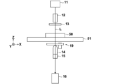
- the observation apparatus of the present invention may further include a vertical direction moving mechanism that integrally moves the imaging optical system, the imaging optical system drive unit, and the displacement sensor in the vertical direction.
- the imaging optical system drive unit includes a piezoelectric element, and the objective lens can be moved in the optical axis direction using the piezoelectric element.
- a laser displacement sensor can be used as the displacement sensor.
- the observation method of the present invention at least one of a stage on which a container in which an observation object is accommodated and an objective lens that forms an image of the observation object in the container is formed in the main scanning direction and the main scanning direction.
- the position of the container at a position on the front side in the moving direction of the observation area with respect to the position of the observation area of the imaging optical system with respect to the container The position in the vertical direction is detected using at least one displacement sensor, and the objective lens is moved in the optical axis direction based on the detected position in the vertical direction of the container, and the moving direction in the main scanning direction is changed.
- the position of the displacement sensor in the main scanning direction or the displacement sensor to be used is switched.
- An observation apparatus control program includes at least one of a stage on which a container in which an observation object is accommodated and an imaging optical system having an objective lens that forms an image of the observation object in the container in the main scanning direction and the main scanning direction.
- an observation apparatus control program for causing a computer to execute a procedure for moving in the sub-scanning direction orthogonal to the scanning direction and reciprocating at least one of the above in the main scanning direction, the observation is performed more than the position of the observation area of the imaging optical system relative to the container.
- the objective lens is moved in the direction of the optical axis based on the procedure of detecting the vertical position of the container at the front position in the moving direction of the area using at least one displacement sensor and the detected vertical position of the container.
- the displacement sensor position in the main scanning direction or the displacement sensor to be used according to the change of the moving direction in the main scanning direction. Characterized in that to perform the procedure for switching the computer.
- the observation apparatus and method and the observation apparatus control program of the present invention at least one of the stage on which the container is installed and the imaging optical system that forms an image of the observation target in the container is arranged in the main scanning direction and the sub scanning direction. And at least one of them is reciprocated in the main scanning direction.
- the stage or the imaging optical system is moved back and forth in the main scanning direction to scan the observation area of the imaging optical system, so that the stage is moved only in one direction as described in Patent Document 1 and observed.
- the scanning time of the observation area can be shortened.
- the position in the vertical direction of the container at the position on the front side in the moving direction of the observation area relative to the position of the observation area of the imaging optical system with respect to the container is detected using at least one displacement sensor, and the detection is performed. Since the autofocus control is performed by moving the objective lens in the optical axis direction based on the vertical position of the container, the autofocus control is performed based on the contrast of the captured image as in Patent Document 1. Compared with the case where it is performed, the autofocus control can be performed at high speed.
- the position of the displacement sensor in the main scanning direction or the displacement sensor to be used is switched in accordance with the change in the moving direction in the main scanning direction.
- the position of the container can always be detected prior to imaging.
- the figure which shows schematic structure of the microscope observation system using 1st Embodiment of the observation apparatus of this invention Schematic diagram showing the configuration of the imaging optical system Perspective view showing the structure of the stage
- Diagram showing the scanning position of the observation area in the culture vessel The figure which shows the positional relationship with an imaging optical system, the 1st displacement sensor, the 2nd displacement sensor, and culture
- the figure for demonstrating switching with a 1st displacement sensor and a 2nd displacement sensor The figure for demonstrating an example of the timing of autofocus control
- the block diagram which shows schematic structure of the microscope observation system using 2nd Embodiment of the observation apparatus of this invention.
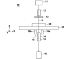
- FIG. 1 is a block diagram showing a schematic configuration of a microscope apparatus 10 in the microscope observation system of the present embodiment.
- the microscope apparatus 10 captures a phase difference image of cultured cells that are observation targets.
- the microscope apparatus 10 includes a white light source 11 that emits white light, a condenser lens 12, a slit plate 13, an imaging optical system 14, and an imaging optical system drive unit. 15, an image sensor 16, and a detection unit 18.
- the slit plate 13 is provided with a ring-shaped slit that transmits white light to the light-shielding plate that blocks white light emitted from the white light source 11, and the ring shape is obtained when white light passes through the slit. Illumination light L is formed.
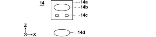
- FIG. 2 is a diagram showing a detailed configuration of the imaging optical system 14.
- the imaging optical system 14 includes a phase difference lens 14a and an imaging lens 14d.
- the phase difference lens 14a includes an objective lens 14b and a phase plate 14c.
- the phase plate 14 c is formed by forming a phase ring on a transparent plate that is transparent with respect to the wavelength of the illumination light L.
- the slit size of the slit plate 13 described above is in a conjugate relationship with the phase ring of the phase plate 14c.
- the phase ring is a ring in which a phase film that shifts the phase of incident light by a quarter wavelength and a neutral density filter that attenuates incident light are formed.
- the phase ring passes through the phase ring, the phase is shifted by 1 ⁇ 4 wavelength, and the brightness is weakened.
- most of the diffracted light diffracted by the observation object passes through the transparent plate of the phase plate 14c, and its phase and brightness do not change.
- the phase difference lens 14a having the objective lens 14b is moved in the optical axis direction of the objective lens 14b by the imaging optical system driving unit 15 shown in FIG.
- the objective lens 14b, the optical axis direction, and the Z direction are the same direction.
- the autofocus control is performed by the movement of the phase difference lens 14a in the Z direction, and the contrast of the phase difference image captured by the image sensor 16 is adjusted.
- the magnification of the phase difference lens 14a may be changed.
- the phase difference lens 14a or the imaging optical system 14 having different magnifications may be configured to be exchangeable. The exchange of the phase difference lens 14a or the imaging optical system 14 may be performed automatically or manually by the user.
- the imaging optical system driving unit 15 includes an actuator such as a piezoelectric element, and is driven based on a control signal output from the imaging optical system control unit 21 described later.
- the imaging optical system drive unit 15 is configured to pass the phase difference image that has passed through the phase difference lens 14a as it is.
- the configuration of the imaging optical system drive unit 15 is not limited to a piezoelectric element, and any other configuration that can move the phase difference lens 14a in the Z direction may be used.
- the imaging lens 14 d receives the phase difference image that has passed through the phase difference lens 14 a and the imaging optical system driving unit 15, and forms an image on the image sensor 16.
- the imaging device 16 captures the phase difference image formed by the imaging lens 14d.
- a CCD (Charge-Coupled Device) image sensor or a CMOS (Complementary Metal-Oxide Semiconductor) image sensor is used.
- CMOS Complementary Metal-Oxide Semiconductor
- an image sensor provided with RGB (Red Green Blue) color filters may be used, or a monochrome image sensor may be used.
- the detection unit 18 detects the position of the culture vessel 50 installed on the stage 51 in the Z direction (vertical direction).
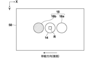
- the detection unit 18 includes a first displacement sensor 18a and a second displacement sensor 18b.
- the first displacement sensor 18a and the second displacement sensor 18b are arranged side by side in the X direction shown in FIG. 1 with the phase difference lens 14a interposed therebetween.
- the first displacement sensor 18a and the second displacement sensor 18b in this embodiment are laser displacement meters, which irradiate the culture vessel 50 with laser light and detect the reflected light, thereby detecting Z on the bottom surface of the culture vessel 50. Detect the position of the direction.
- the bottom surface of the culture vessel 50 is a boundary surface between the bottom portion of the culture vessel 50 and the cell to be observed, that is, the observation target installation surface.
- the position information in the Z direction of the culture vessel 50 detected by the detection unit 18 is output to the imaging optical system control unit 21, and the imaging optical system control unit 21 performs imaging optics based on the input position information.
- the system drive unit 15 is controlled to perform autofocus control. The detection of the position of the culture vessel 50 by the first displacement sensor 18a and the second displacement sensor 18b and the auto-autofocus control by the imaging optical system control unit 21 will be described in detail later.
- a stage 51 is provided between the slit plate 13, the phase difference lens 14 a and the detection unit 18. On the stage 51, a culture vessel 50 in which cells to be observed are accommodated is installed.
- the culture vessel 50 a petri dish, a dish, a well plate, or the like can be used.
- the cells contained in the culture vessel 50 include pluripotent stem cells such as iPS cells and ES cells, nerves, skin, myocardium and liver cells induced to differentiate from the stem cells, and skin, retina extracted from the human body, Examples include heart muscle, blood cells, nerve and organ cells.
- the stage 51 is moved in the X and Y directions orthogonal to each other by a horizontal driving unit 17 (see FIG. 4) described later.
- the X direction and the Y direction are directions orthogonal to the Z direction, and are directions orthogonal to each other in the horizontal plane.
- the X direction is the main scanning direction
- the Y direction is the sub-scanning direction.
- FIG. 3 is a diagram illustrating an example of the stage 51.
- a rectangular opening 51a is formed.
- the culture vessel 50 is installed on the member forming the opening 51a, and the phase difference image of the cells in the culture vessel 50 is configured to pass through the opening 51a.
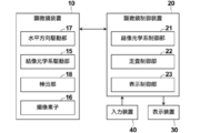
- FIG. 4 is a block diagram showing the configuration of the microscope observation system of the present embodiment.
- the block diagram of the one part structure controlled by each part of the microscope control apparatus 20 is shown.
- the microscope control device 20 controls the entire microscope device 10, and particularly includes an imaging optical system control unit 21, a scanning control unit 22, and a display control unit 23.
- the microscope control device 20 is composed of a computer including a central processing unit, a semiconductor memory, a hard disk, and the like, and an embodiment of the observation device control program of the present invention is installed on the hard disk. Then, when the observation apparatus control program is executed by the central processing unit, the imaging optical system control unit 21, the scanning control unit 22, and the display control unit 23 shown in FIG. 4 function.
- the imaging optical system control unit 21 controls the imaging optical system driving unit 15 based on the position information in the Z direction of the culture vessel 50 detected by the detection unit 18 as described above. Then, the objective lens 14b of the imaging optical system 14 is moved in the optical axis direction by driving the imaging optical system driving unit 15, and autofocus control is performed.
- the scanning control unit 22 drives and controls the horizontal direction driving unit 17, thereby moving the stage 51 in the X direction and the Y direction.
- the horizontal direction drive part 17 is comprised from the actuator which has a piezoelectric element etc.
- FIG. 5 is a diagram showing the scanning position of the observation area in the culture vessel 50 by a solid line M.
- a well plate having six wells W is used as the culture vessel 50.
- the observation area of the imaging optical system 14 moves along the solid line M from the scanning start point S to the scanning end point E. That is, the observation area is scanned in the positive X direction (rightward in FIG. 5), then moved in the Y direction (downward in FIG. 5), and scanned in the opposite negative direction (leftward in FIG. 5). Is done. The observation area then moves again in the Y direction and is scanned again in the positive direction. In this way, the observation area is scanned two-dimensionally in the culture vessel 50 by repeatedly performing reciprocal movement in the X direction and movement in the Y direction.
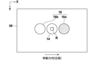
- FIGS. 6 and 7 show the positions of the imaging optical system 14, the first displacement sensor 18 a and the second displacement sensor 18 b, and the culture vessel 50 when the observation region R is at an arbitrary position in the culture vessel 50. It is the figure which showed the relationship.
- a first displacement sensor 18a and a second displacement sensor 18b are provided side by side in the X direction with the imaging optical system 14 interposed therebetween.
- the observation region R of the imaging optical system 14 is scanned two-dimensionally within the culture vessel 50 as described above. At this time, from the position of the observation region R of the imaging optical system 14 with respect to the culture vessel 50 In addition, the position of the culture vessel 50 in the Z direction is detected at the position in front of the observation area R in the moving direction. Specifically, when the observation area R moves in the direction of the arrow shown in FIG. 6 (the right direction in FIG. 6), the observation area R out of the first displacement sensor 18a and the second displacement sensor 18b.
- the position of the culture vessel 50 in the Z direction is detected by the first displacement sensor 18a on the front side in the R movement direction. Then, when the observation area R moves from the position shown in FIG. 6 to the position of the first displacement sensor 18a, autofocus control is performed using the previously detected position information of the culture vessel 50 in the Z direction. Then, a phase difference image is captured.
- the imaging optical system control unit 21 controls the imaging optical system drive unit 15 based on the position information in the Z direction of the culture vessel 50 detected in advance as described above, thereby performing autofocus. Take control. Specifically, in the imaging optical system control unit 21, the relationship between the position information of the culture vessel 50 in the Z direction and the amount of movement of the imaging optical system 14 in the optical axis direction is set in advance. The imaging optical system control unit 21 obtains the movement amount of the imaging optical system 14 in the optical axis direction based on the input position information of the culture vessel 50 in the Z direction, and concludes a control signal corresponding to the movement amount. The image is output to the image optical system driving unit 15. The imaging optical system drive unit 15 is driven based on the input control signal, whereby the imaging optical system 14 (objective lens 14b) moves in the optical axis direction, and corresponds to the position of the culture vessel 50 in the Z direction. Focus adjustment is performed.
- the detection timing of the position of the culture vessel 50 in each observation region R and the phase difference image The imaging timing is shifted in time. Therefore, the movement of the imaging optical system 14 (objective lens 14b) in the Z direction, that is, the autofocus control is performed after the position of the culture vessel 50 is detected by the first displacement sensor 18a or the second displacement sensor 18b. This is performed until the observation area R reaches the detection position.
- the position of the culture vessel 50 in the Z direction may be shifted due to some factor after the autofocus control until the observation area R reaches the detection position. There is a possibility that the focus position shifts.
- the autofocus control timing is just before the observation area R reaches the detection position, and the timing is sufficient to capture the phase difference image at the detection position.
- the observation area R sequentially moves in the X direction, and the detection position by the detection unit 18 is the position of Pd indicated by diagonal lines.
- the observation area R is from the time when it passes through the position Pr of the observation area R adjacent to the detection position Pd to the time when it reaches the detection position Pd.
- the autofocus control may be performed when the observation area R reaches the detection position Pd.
- the autofocus using the position information of the detection position from the detection timing by the first or second displacement sensor 18a and 18b so that the autofocus control timing becomes a desirable timing as described above.
- the time until the control timing is set in advance.
- the preset time is changed in accordance with the changing of the moving speed of the stage 51. Also good.
- the first displacement sensor 18a is moved by moving the first displacement sensor 18a or the second displacement sensor 18b in the X direction.
- the distance between the second displacement sensor 18b and the imaging optical system 14 may be changed.
- the first displacement sensor 18a and the second displacement sensor 18b are provided side by side in the X direction with the imaging optical system 14 interposed therebetween, and the culture vessel 50 is provided prior to the imaging of the phase difference image.
- the imaging optical system 14 In the case of detecting the position, in order to detect the position of the culture vessel 50 and capture the phase difference image in the entire range of the culture vessel 50, as shown in FIG. It is necessary to relatively move the imaging optical system 14, the first displacement sensor 18a, and the second displacement sensor 18b to the ranges R1 and R2.
- the width in the X direction of the range R1 is desirably the distance in the X direction between the first displacement sensor 18a and the imaging optical system 14, and the width in the X direction of the range R2 is the second displacement sensor 18b. It is desirable that the distance between the image forming optical system 14 and the imaging optical system 14 is X.
- the stage 51 when the observation region R is scanned in the range of the culture vessel 50 by moving the stage 51 in the X direction, it is desirable that the moving speed of the observation region R in the range of the culture vessel 50 is constant. Therefore, when the stage 51 starts to move in the X direction, it is necessary to accelerate until the stage 51 reaches a constant speed, and when the stage 51 finishes moving in the X direction, the stage 51 is decelerated from the constant speed and stopped. There is a need.
- the moving speed of the stage 51 in the X direction is set to a constant speed, it is possible to control the speed rapidly to a constant speed with almost no acceleration region, but when such control is performed, The liquid level of the culture solution or the like stored together with the cells in the culture vessel 50 may be shaken, leading to a decrease in the image quality of the phase difference image.
- a similar problem may occur when the stage 51 is stopped.
- the range R1 and the range R2 shown in FIG. 5 are set as the acceleration / deceleration range of the movement of the stage 51 in the X direction.
- the observation area R is scanned at a constant speed in the range of the culture container 50 without unnecessarily widening the scanning range. Can do.
- the shaking of the liquid level of the culture solution as described above can also be suppressed.
- the display control unit 23 generates a single composite phase difference image by combining the phase difference images of each observation region R imaged by the microscope apparatus 10, and the composite phase difference is generated.
- the image is displayed on the display device 30.
- the display device 30 displays the composite phase difference image generated by the display control unit 23 as described above, and includes, for example, a liquid crystal display. Further, the display device 30 may be configured by a touch panel and may also be used as the input device 40.
- the input device 40 includes a mouse and a keyboard, and accepts various setting inputs by the user.
- the input device 40 according to the present embodiment receives setting inputs such as an instruction to change the magnification of the phase difference lens 14a and an instruction to change the moving speed of the stage.
- the culture vessel 50 in which cells to be observed are accommodated is placed on the stage 51 (S10).
- the stage 51 moves, the observation area R of the imaging optical system 14 is set to the position of the scanning start point S shown in FIG. 5, and scanning of the observation area R is started (S12).
- the position of the culture vessel 50 is detected in advance for each observation area R, and when the observation area R reaches the detection position, a phase difference image is captured. Is done. Then, the position detection of the culture vessel 50 and the imaging of the phase difference image are performed while scanning the observation area R, and the phase difference image of the observation area R at a certain position and the front side of the scanning direction from the position are scanned. The position detection of the culture vessel 50 at the position is performed in parallel.
- the imaging optical system control unit 21 calculates the amount of movement of the imaging optical system 14 (objective lens 14b) in the Z direction based on the acquired position information of the culture vessel 50 in the Z direction (S16), and the movement thereof. The amount is stored together with the position on the XY coordinate of the detection position of the culture vessel 50 (S18).
- the observation area R moves toward the position where the position of the culture vessel 50 is detected by the first displacement sensor 18a in S18 (S20).
- the imaging optical system control unit 21 reads the movement amount immediately before the observation region R reaches the position where the position of the culture vessel 50 is detected, and performs autofocus control based on the movement amount (S22, S22). S24). That is, the imaging optical system control unit 21 drives and controls the imaging optical system driving unit 15 based on the movement amount stored in advance, and moves the imaging optical system 14 in the Z direction. Then, after the autofocus control, a phase difference image is taken when the observation region R reaches the position where the position of the culture vessel 50 is detected (S26).
- the phase difference image in the observation area R is output from the image sensor 16 to the display control unit 23 and stored. As described above, while the phase difference image in the observation area R is being captured in S26, the position detection of the culture vessel 50 is performed in parallel at the position in front of the observation area R in the scanning direction. .
- the displacement sensor to be used is switched from the first displacement sensor 18a to the second displacement sensor 18b (S30).
- the displacement sensor to be used is switched every time the observation area R moves to the acceleration / deceleration area R1 and R2, and the processes from S14 to S26 are repeated until all the scans are completed. Then, when the observation area R reaches the position of the scanning end point E shown in FIG. 5, all scanning is completed (S32, YES).
- the display control unit 23 combines the phase difference images of each observation region R to generate a combined phase difference image (S34), and displays the generated combined phase difference image on the display device 30. (S36).
- FIG. 10 is a diagram illustrating a schematic configuration of the microscope observation system according to the second embodiment.
- the microscope observation system of the second embodiment differs from the microscope observation system of the first embodiment in the configuration of the detection unit. Since the other configuration of the microscope observation system according to the second embodiment is the same as that of the first embodiment, the configuration of the detection unit of the microscope observation system according to the second embodiment will be mainly described below.
- the detection unit 18 of the first embodiment includes two displacement sensors, and the displacement unit to be used is switched according to the change in the moving direction of the observation area R.
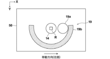
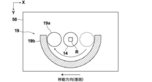
- the detection unit 19 of the second embodiment One displacement sensor is provided, and the position of the displacement sensor is switched according to the change in the moving direction of the observation area R.
- the detection unit 19 includes a displacement sensor 19a and a guide mechanism 19b that guides the displacement sensor 19a and moves the position thereof.
- the displacement sensor 19a is the same as the first and second displacement sensors 18a and 18b of the first embodiment, and includes a laser displacement sensor.
- the guide mechanism 19b includes a semicircular arc guide member, and moves the displacement sensor 19a along the guide member.
- the guide member moves the displacement sensor 19a from one side to the other side in the X direction across the imaging optical system 14 (objective lens 14b).
- FIG. 11 is a diagram showing the position of the displacement sensor 19a when the moving direction of the observation area R is the arrow direction in FIG. 11 (the right direction in FIG. 11).
- FIG. 12 is a diagram showing the position of the displacement sensor 19a when the moving direction of the observation area R is the arrow direction in FIG. 12 (left direction in FIG. 12).
- the above-described guide mechanism 19b is provided as a displacement sensor moving mechanism for moving the position of the displacement sensor.
- the configuration of the displacement sensor moving mechanism is not limited to this, and the position of the displacement sensor is determined. Other configurations may be used as long as the configurations can be similarly changed.
- the detection units 18 and 19 detect the position of the culture vessel 50 in the Z direction and perform autofocus control using the detection information. For example, when the bottom of the culture vessel 50 is installed so as to float from the installation surface of the stage 51 or when the bottom of the culture vessel 50 is thick, the distance between the imaging optical system 14 and the bottom of the culture vessel 50 becomes large. Even when the imaging optical system drive unit 15 moves the imaging optical system 14 to the maximum in the Z direction, the position of the bottom surface of the culture vessel 50 does not fall within the range of the depth of field of the imaging optical system 14. There is a case.
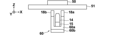
- the imaging optical system 14, the imaging optical system drive unit 15, the first displacement sensor 18a, and the second displacement sensor 18b are integrally formed in the Z direction. It is desirable to provide a vertical direction moving mechanism 60 for moving to the right.
- the vertical movement mechanism 60 includes a holding unit 60a that integrally holds the imaging optical system 14, the imaging optical system driving unit 15, the first displacement sensor 18a, and the second displacement sensor 18b, and the holding unit 60a as Z. And a Z-direction drive unit 60b that moves in the direction.
- the holding unit 60a holds the image forming optical system 14, the image forming optical system driving unit 15, the first displacement sensor 18a, and the second displacement sensor 18b while maintaining the relative positional relationship therebetween.
- the Z direction drive unit 60b includes an actuator such as a piezoelectric element.
- the vertical movement mechanism 60 is configured to pass the phase difference image formed by the imaging optical system 14 as it is.
- the imaging optical system 14, the imaging optical system driving unit 15, the first displacement sensor 18a, and the second displacement sensor 18b are moved using the vertical direction moving mechanism 60. By moving in the Z direction integrally, calibration of autofocus control is performed.
- the calibration first sets the position of the imaging optical system 14 in the Z direction as a reference position by driving the imaging optical system drive unit 15.
- This reference position is a reference position in the above-described autofocus control, and is the center position of the moving range of the imaging optical system 14 in the Z direction.
- the image formed by the imaging optical system 14 at each position is detected by the imaging element 16, and a phase difference image at each position is acquired. .
- a position where the contrast of the phase difference image is maximized is detected.
- the position where the contrast of the phase difference image becomes maximum for example, when the holding unit 60a is sequentially moved upward in the vertical direction, the position where the phase difference image is out of focus and the holding unit 60a are sequentially moved downward in the vertical direction. In this case, the position where the phase difference image is out of focus may be detected, and the center position of these detection positions may be detected as the position where the contrast of the phase difference image is maximized.
- the position where the contrast of the phase difference image is maximized is set as the reference position of the vertical movement mechanism 60, and the calibration is completed.
- the calibration may be performed at the center of gravity of the bottom of the culture vessel 50, for example, but may be performed at a plurality of locations on the bottom of the culture vessel 50. In that case, the average of the reference positions respectively detected at the plurality of locations may be set as the final reference position.
- FIG. 13 is a diagram illustrating an example in which a vertical movement mechanism 61 is provided in the microscope observation system of the second embodiment.
- the vertical movement mechanism 61 includes a holding unit 61a that integrally holds the imaging optical system 14, the imaging optical system driving unit 15, and the detection unit 19, and a Z-direction driving unit 61b that moves the holding unit 61a in the Z direction. It has.
- the holding unit 61 a holds the image forming optical system 14, the image forming optical system driving unit 15, and the displacement sensor 19 a of the detecting unit 19 while maintaining the relative positional relationship therebetween.
- the Z-direction drive unit 61b includes an actuator such as a piezoelectric element, for example, similarly to the Z-direction drive unit 60b described above.
- the calibration method is the same as in the case of the microscope observation system of the first embodiment described above.
- the observation area R is scanned by moving the stage 51.
- the present invention is not limited to this, and the stage 51 is fixed, and the imaging optical system 14 and other phase difference images are captured.
- the observation area R may be scanned by moving the configuration related to the observation area, or the observation area R may be moved by moving both the stage 51 and the imaging optical system 14 and other configurations related to imaging of the phase difference image. R may be scanned.
- the present invention is applied to a phase contrast microscope.
- the present invention is not limited to the phase contrast microscope, and is applied to other microscopes such as a differential interference microscope and a bright field microscope. Also good.
- the phase difference image formed by the image forming optical system 14 is picked up by the image pickup device 16, but the image is formed by the image forming optical system 14 without providing the image pickup device.
- An observation optical system or the like may be provided so that the user can directly observe the phase difference image of the observation target.
Landscapes
- Physics & Mathematics (AREA)
- General Physics & Mathematics (AREA)
- Optics & Photonics (AREA)
- Chemical & Material Sciences (AREA)
- Analytical Chemistry (AREA)
- Engineering & Computer Science (AREA)
- Health & Medical Sciences (AREA)
- Biomedical Technology (AREA)
- Life Sciences & Earth Sciences (AREA)
- Organic Chemistry (AREA)
- General Engineering & Computer Science (AREA)
- Biotechnology (AREA)
- Wood Science & Technology (AREA)
- Bioinformatics & Cheminformatics (AREA)
- Genetics & Genomics (AREA)
- Zoology (AREA)
- Cell Biology (AREA)
- Microbiology (AREA)
- Biochemistry (AREA)
- General Health & Medical Sciences (AREA)
- Computer Vision & Pattern Recognition (AREA)
- Microscoopes, Condenser (AREA)
- Automatic Focus Adjustment (AREA)
- Focusing (AREA)
Abstract
L'invention concerne un dispositif et un procédé d'observation ainsi qu'un programme de commande d'observation avec lesquels la vitesse de commande de mise au point automatique dans chaque zone d'observation peut être accrue et le temps de balayage dans chaque zone d'observation peut être réduit. La présente invention comprend : une platine (51) ; un système optique d'imagerie (14) comprenant une lentille d'objectif ; une unité de détection (18) comprenant des capteurs de déplacement (18a, 18b) qui détectent la position dans la direction verticale d'un récipient de culture (50) ; une unité de commande de système optique d'imagerie (21) qui commande une unité d'entraînement de système optique d'imagerie (15) sur la base de la position de direction verticale du récipient de culture (50) afin de déplacer la lentille d'objectif dans la direction de l'axe optique ; et une unité d'entraînement en direction horizontale (17) qui déplace la platine (51) dans une direction de balayage principale et une direction de balayage secondaire et qui déplace réciproquement la platine (51) dans la direction de balayage principale. L'unité de détection (18) détecte la position de direction verticale du récipient de culture (50) à une position dans la zone d'observation davantage vers le côté avant dans la direction de déplacement que la position dans la zone d'observation du système optique d'imagerie (14) par rapport au récipient de culture (50), et commute le capteur de déplacement à être utilisé selon des changements dans la direction de déplacement dans la direction de balayage principale.
Priority Applications (3)
| Application Number | Priority Date | Filing Date | Title |
|---|---|---|---|
| EP17798974.6A EP3460557B1 (fr) | 2016-05-17 | 2017-03-03 | Dispositif et procédé d'observation, et programme de commande de dispositif d'observation |
| KR1020187031959A KR102116199B1 (ko) | 2016-05-17 | 2017-03-03 | 관찰 장치 및 방법과 관찰 장치 제어 프로그램 |
| US16/177,577 US11009689B2 (en) | 2016-05-17 | 2018-11-01 | Observation device, observation method, and observation device control program |
Applications Claiming Priority (2)
| Application Number | Priority Date | Filing Date | Title |
|---|---|---|---|
| JP2016098541A JP6698421B2 (ja) | 2016-05-17 | 2016-05-17 | 観察装置および方法並びに観察装置制御プログラム |
| JP2016-098541 | 2016-05-17 |
Related Child Applications (1)
| Application Number | Title | Priority Date | Filing Date |
|---|---|---|---|
| US16/177,577 Continuation US11009689B2 (en) | 2016-05-17 | 2018-11-01 | Observation device, observation method, and observation device control program |
Publications (1)
| Publication Number | Publication Date |
|---|---|
| WO2017199537A1 true WO2017199537A1 (fr) | 2017-11-23 |
Family
ID=60326391
Family Applications (1)
| Application Number | Title | Priority Date | Filing Date |
|---|---|---|---|
| PCT/JP2017/008563 Ceased WO2017199537A1 (fr) | 2016-05-17 | 2017-03-03 | Dispositif et procédé d'observation, et programme de commande de dispositif d'observation |
Country Status (5)
| Country | Link |
|---|---|
| US (1) | US11009689B2 (fr) |
| EP (1) | EP3460557B1 (fr) |
| JP (1) | JP6698421B2 (fr) |
| KR (1) | KR102116199B1 (fr) |
| WO (1) | WO2017199537A1 (fr) |
Cited By (1)
| Publication number | Priority date | Publication date | Assignee | Title |
|---|---|---|---|---|
| WO2020066503A1 (fr) * | 2018-09-27 | 2020-04-02 | 富士フイルム株式会社 | Système d'observation et procédé d'observation et programme de commande de système d'observation |
Families Citing this family (1)
| Publication number | Priority date | Publication date | Assignee | Title |
|---|---|---|---|---|
| JP7109130B2 (ja) * | 2018-04-04 | 2022-07-29 | 株式会社エビデント | 顕微鏡 |
Citations (3)
| Publication number | Priority date | Publication date | Assignee | Title |
|---|---|---|---|---|
| JPH10307252A (ja) * | 1997-05-07 | 1998-11-17 | Hitachi Denshi Ltd | 自動合焦点光学式テレビカメラ顕微鏡 |
| JP2003295065A (ja) * | 2002-03-29 | 2003-10-15 | Natl Inst Of Radiological Sciences | 顕微鏡装置 |
| US20150309297A1 (en) * | 2011-06-08 | 2015-10-29 | Carl Zeiss Microscopy Gmbh | Autofocus method for microscope and microscope comprising autofocus device |
Family Cites Families (11)
| Publication number | Priority date | Publication date | Assignee | Title |
|---|---|---|---|---|
| JP2000266995A (ja) * | 1999-03-18 | 2000-09-29 | Hitachi Denshi Ltd | 顕微鏡合焦点検出方法 |
| US6924929B2 (en) * | 2002-03-29 | 2005-08-02 | National Institute Of Radiological Sciences | Microscope apparatus |
| US20050089208A1 (en) * | 2003-07-22 | 2005-04-28 | Rui-Tao Dong | System and method for generating digital images of a microscope slide |
| JP4936841B2 (ja) * | 2006-09-28 | 2012-05-23 | 株式会社キーエンス | 共焦点顕微鏡、共焦点顕微鏡操作方法、共焦点顕微鏡操作プログラム及びコンピュータで読み取り可能な記録媒体並びに記録した機器 |
| JP5043629B2 (ja) | 2007-12-17 | 2012-10-10 | オリンパス株式会社 | レーザ走査型顕微鏡及びその表面形状の測定方法 |
| JP5340820B2 (ja) * | 2009-06-19 | 2013-11-13 | オリンパス株式会社 | 共焦点レーザ顕微鏡 |
| JP2011081211A (ja) | 2009-10-07 | 2011-04-21 | Olympus Corp | 顕微鏡システム |
| US20130169788A1 (en) * | 2010-10-29 | 2013-07-04 | Canon Kabushiki Kaisha | Microscope, image acquisition apparatus, and image acquisition system |
| EP2845045B1 (fr) * | 2012-05-02 | 2023-07-12 | Leica Biosystems Imaging, Inc. | Mise au point en temps réel en imagerie à balayage linéaire |
| CN103852878B (zh) * | 2014-01-08 | 2016-05-25 | 麦克奥迪实业集团有限公司 | 一种具有实时聚焦的显微切片快速数字扫描装置及其方法 |
| WO2016022359A1 (fr) * | 2014-08-06 | 2016-02-11 | Cellomics, Inc. | Système de mise au point automatique laser à base d'image |
-
2016
- 2016-05-17 JP JP2016098541A patent/JP6698421B2/ja active Active
-
2017
- 2017-03-03 WO PCT/JP2017/008563 patent/WO2017199537A1/fr not_active Ceased
- 2017-03-03 KR KR1020187031959A patent/KR102116199B1/ko active Active
- 2017-03-03 EP EP17798974.6A patent/EP3460557B1/fr active Active
-
2018
- 2018-11-01 US US16/177,577 patent/US11009689B2/en active Active
Patent Citations (3)
| Publication number | Priority date | Publication date | Assignee | Title |
|---|---|---|---|---|
| JPH10307252A (ja) * | 1997-05-07 | 1998-11-17 | Hitachi Denshi Ltd | 自動合焦点光学式テレビカメラ顕微鏡 |
| JP2003295065A (ja) * | 2002-03-29 | 2003-10-15 | Natl Inst Of Radiological Sciences | 顕微鏡装置 |
| US20150309297A1 (en) * | 2011-06-08 | 2015-10-29 | Carl Zeiss Microscopy Gmbh | Autofocus method for microscope and microscope comprising autofocus device |
Non-Patent Citations (1)
| Title |
|---|
| See also references of EP3460557A4 * |
Cited By (3)
| Publication number | Priority date | Publication date | Assignee | Title |
|---|---|---|---|---|
| WO2020066503A1 (fr) * | 2018-09-27 | 2020-04-02 | 富士フイルム株式会社 | Système d'observation et procédé d'observation et programme de commande de système d'observation |
| JPWO2020066503A1 (ja) * | 2018-09-27 | 2021-08-30 | 富士フイルム株式会社 | 観察装置および方法並びに観察装置制御プログラム |
| US12061326B2 (en) | 2018-09-27 | 2024-08-13 | Fujifilm Corporation | Observation device, observation method, and observation device control program |
Also Published As
| Publication number | Publication date |
|---|---|
| KR20180126585A (ko) | 2018-11-27 |
| JP6698421B2 (ja) | 2020-05-27 |
| KR102116199B1 (ko) | 2020-05-27 |
| JP2017207567A (ja) | 2017-11-24 |
| US20190072749A1 (en) | 2019-03-07 |
| US11009689B2 (en) | 2021-05-18 |
| EP3460557B1 (fr) | 2022-12-14 |
| EP3460557A4 (fr) | 2019-06-26 |
| EP3460557A1 (fr) | 2019-03-27 |
Similar Documents
| Publication | Publication Date | Title |
|---|---|---|
| US20190121058A1 (en) | Imaging device, imaging method and imaging control program | |
| WO2018154924A1 (fr) | Dispositif microscopique, procédé d'observation, et programme de commande pour dispositif microscopique | |
| JP6619315B2 (ja) | 観察装置および方法並びに観察装置制御プログラム | |
| EP3457192B1 (fr) | Dispositif et procédé d'imagerie, et programme de commande de dispositif d'imagerie | |
| JP6824388B2 (ja) | 観察装置および観察制御方法並びに観察制御プログラム | |
| JP6698421B2 (ja) | 観察装置および方法並びに観察装置制御プログラム | |
| JP6667411B2 (ja) | 観察装置および方法並びに観察装置制御プログラム | |
| JPWO2019202979A1 (ja) | 観察装置、観察装置の作動方法、及び観察制御プログラム | |
| JP6861842B2 (ja) | 観察装置および方法並びに観察装置制御プログラム | |
| JP6812562B2 (ja) | 観察装置および方法並びに観察装置制御プログラム | |
| JP6848086B2 (ja) | 観察装置および方法並びに観察装置制御プログラム |
Legal Events
| Date | Code | Title | Description |
|---|---|---|---|
| ENP | Entry into the national phase |
Ref document number: 20187031959 Country of ref document: KR Kind code of ref document: A |
|
| NENP | Non-entry into the national phase |
Ref country code: DE |
|
| 121 | Ep: the epo has been informed by wipo that ep was designated in this application |
Ref document number: 17798974 Country of ref document: EP Kind code of ref document: A1 |
|
| ENP | Entry into the national phase |
Ref document number: 2017798974 Country of ref document: EP Effective date: 20181217 |