WO2017208306A1 - 自動走行作業車両 - Google Patents
自動走行作業車両 Download PDFInfo
- Publication number
- WO2017208306A1 WO2017208306A1 PCT/JP2016/065918 JP2016065918W WO2017208306A1 WO 2017208306 A1 WO2017208306 A1 WO 2017208306A1 JP 2016065918 W JP2016065918 W JP 2016065918W WO 2017208306 A1 WO2017208306 A1 WO 2017208306A1
- Authority
- WO
- WIPO (PCT)
- Prior art keywords
- steering
- target
- deviation
- value
- calculation unit
- Prior art date
- Legal status (The legal status is an assumption and is not a legal conclusion. Google has not performed a legal analysis and makes no representation as to the accuracy of the status listed.)
- Ceased
Links
Images


Classifications
-
- A—HUMAN NECESSITIES
- A01—AGRICULTURE; FORESTRY; ANIMAL HUSBANDRY; HUNTING; TRAPPING; FISHING
- A01B—SOIL WORKING IN AGRICULTURE OR FORESTRY; PARTS, DETAILS, OR ACCESSORIES OF AGRICULTURAL MACHINES OR IMPLEMENTS, IN GENERAL
- A01B69/00—Steering of agricultural machines or implements; Guiding agricultural machines or implements on a desired track
- A01B69/007—Steering or guiding of agricultural vehicles, e.g. steering of the tractor to keep the plough in the furrow
- A01B69/008—Steering or guiding of agricultural vehicles, e.g. steering of the tractor to keep the plough in the furrow automatic
-
- B—PERFORMING OPERATIONS; TRANSPORTING
- B60—VEHICLES IN GENERAL
- B60W—CONJOINT CONTROL OF VEHICLE SUB-UNITS OF DIFFERENT TYPE OR DIFFERENT FUNCTION; CONTROL SYSTEMS SPECIALLY ADAPTED FOR HYBRID VEHICLES; ROAD VEHICLE DRIVE CONTROL SYSTEMS FOR PURPOSES NOT RELATED TO THE CONTROL OF A PARTICULAR SUB-UNIT
- B60W10/00—Conjoint control of vehicle sub-units of different type or different function
- B60W10/20—Conjoint control of vehicle sub-units of different type or different function including control of steering systems
-
- B—PERFORMING OPERATIONS; TRANSPORTING
- B62—LAND VEHICLES FOR TRAVELLING OTHERWISE THAN ON RAILS
- B62D—MOTOR VEHICLES; TRAILERS
- B62D6/00—Arrangements for automatically controlling steering depending on driving conditions sensed and responded to, e.g. control circuits
- B62D6/002—Arrangements for automatically controlling steering depending on driving conditions sensed and responded to, e.g. control circuits computing target steering angles for front or rear wheels
-
- B—PERFORMING OPERATIONS; TRANSPORTING
- B62—LAND VEHICLES FOR TRAVELLING OTHERWISE THAN ON RAILS
- B62D—MOTOR VEHICLES; TRAILERS
- B62D6/00—Arrangements for automatically controlling steering depending on driving conditions sensed and responded to, e.g. control circuits
- B62D6/02—Arrangements for automatically controlling steering depending on driving conditions sensed and responded to, e.g. control circuits responsive only to vehicle speed
-
- G—PHYSICS
- G05—CONTROLLING; REGULATING
- G05D—SYSTEMS FOR CONTROLLING OR REGULATING NON-ELECTRIC VARIABLES
- G05D1/00—Control of position, course, altitude or attitude of land, water, air or space vehicles, e.g. using automatic pilots
- G05D1/02—Control of position or course in two dimensions
- G05D1/021—Control of position or course in two dimensions specially adapted to land vehicles
- G05D1/0212—Control of position or course in two dimensions specially adapted to land vehicles with means for defining a desired trajectory
-
- A—HUMAN NECESSITIES
- A01—AGRICULTURE; FORESTRY; ANIMAL HUSBANDRY; HUNTING; TRAPPING; FISHING
- A01D—HARVESTING; MOWING
- A01D41/00—Combines, i.e. harvesters or mowers combined with threshing devices
- A01D41/12—Details of combines
- A01D41/127—Control or measuring arrangements specially adapted for combines
- A01D41/1278—Control or measuring arrangements specially adapted for combines for automatic steering
-
- B—PERFORMING OPERATIONS; TRANSPORTING
- B60—VEHICLES IN GENERAL
- B60W—CONJOINT CONTROL OF VEHICLE SUB-UNITS OF DIFFERENT TYPE OR DIFFERENT FUNCTION; CONTROL SYSTEMS SPECIALLY ADAPTED FOR HYBRID VEHICLES; ROAD VEHICLE DRIVE CONTROL SYSTEMS FOR PURPOSES NOT RELATED TO THE CONTROL OF A PARTICULAR SUB-UNIT
- B60W2520/00—Input parameters relating to overall vehicle dynamics
- B60W2520/10—Longitudinal speed
-
- B—PERFORMING OPERATIONS; TRANSPORTING
- B60—VEHICLES IN GENERAL
- B60W—CONJOINT CONTROL OF VEHICLE SUB-UNITS OF DIFFERENT TYPE OR DIFFERENT FUNCTION; CONTROL SYSTEMS SPECIALLY ADAPTED FOR HYBRID VEHICLES; ROAD VEHICLE DRIVE CONTROL SYSTEMS FOR PURPOSES NOT RELATED TO THE CONTROL OF A PARTICULAR SUB-UNIT
- B60W2710/00—Output or target parameters relating to a particular sub-units
- B60W2710/20—Steering systems
- B60W2710/207—Steering angle of wheels
Definitions
- the present invention relates to an automatic traveling work vehicle that performs automatic steering traveling along a set target traveling route.
- Patent Document 1 discloses a teaching route generation unit based on position information measured by a GPS (Global Positioning System) device.
- GPS Global Positioning System
- a rice transplanter that generates a target route parallel to the generated teaching route and autonomously travels on the target route is disclosed.
- an actual travel route during automatic travel is measured by the GPS unit, and a deviation amount between the target route and the actual travel target route is calculated and compared with a preset threshold value.
- the angle between the target path direction and the traveling direction is used as the amount of deviation. If the amount of deviation exceeds the threshold, the direction of deviation from the reference line is detected and judged, and the deviation to the left is detected.
- the steering device is corrected in the right direction according to the amount of deviation, and if a deviation occurs in the right direction, the steering device is corrected in the left direction according to the amount of deviation.
- a deviation occurs in the steering device in the right direction according to the amount of deviation.
- only the angle formed by the target route direction and the traveling direction is used for steering control as a driving shift, so the target route and the vehicle body are close to each other.
- only the deviation amount is large, or when the target route is far away from the vehicle body even though the deviation amount is small, it is difficult to travel appropriately.
- a target travel route (target track) in which various curvatures are mixed, a lateral shift amount and an azimuth shift amount from the target travel route, and a target travel
- the curvature of the route is measured, and the steering angle corresponding to the two deviation amounts and the curvature is calculated and output.
- a reference point is provided so that the vehicle position is in the normal direction of the target travel route, and relative to the coordinate system, the coordinate system is a relative coordinate system based on the reference point from the absolute coordinate system of the vehicle position.
- the feedforward operation amount according to the deviation amount by proportional control and the feed forward according to the curvature and lateral deviation amount of the target track The steering angle is determined by the amount of operation.
- this traveling control technology may be effective for automobiles traveling on paved roads, but it is useful for farming machines such as rice transplanters, tractors, combines, lawn mowers, and civil engineering machines such as dozers.
- the traveling speed is low, it takes time to eliminate the traveling deviation compared to a vehicle that travels at a high speed at the same steering angle.
- JP ⁇ 2008-131880 A Japanese Unexamined Patent Publication No. 2002-215239 (JP 2002-215239 A)
- an object of the present invention is to provide an automatic traveling work vehicle capable of performing automatic steering traveling with high accuracy even during working traveling along a set target traveling route.
- a second control calculation unit that outputs a second steering value calculated for eliminating the deviation based on the azimuth deviation adjusted in accordance with the first steering value and the second steering value.
- a target steering calculation unit that outputs a target steering value, a steering drive control unit that outputs a steering drive signal with the target steering value as an input, and a steering drive unit that steers steered wheels based on the steering drive signal; It has.
- the target steering value for traveling along the target travel route is output from the position deviation with respect to the target travel route and the azimuth deviation with respect to the target travel route.
- a positional deviation with respect to the target travel route is also taken into consideration. Specifically, a weighting function for deriving a weighting coefficient using the position deviation as a variable is introduced, and at this time, the weighting function tends to decrease as the position deviation increases.
- the weighting coefficient w is obtained by G (d), and G is a function that decreases monotonously or decreases stepwise.
- w is usually a numerical value greater than 0 and less than or equal to 1.
- the weight coefficient w is used in multiplication.
- a vehicle speed calculation unit for calculating a vehicle speed is provided, and the target steering calculation unit is configured to calculate the first steering value and the second steering value.
- an adjustment function for deriving an adjustment coefficient for example, a numerical value greater than 0 and equal to or less than 1 using the vehicle speed as a variable is introduced.
- the adjustment function tends to decrease as the vehicle speed increases.
- K the adjustment coefficient k is obtained by K (k)
- K is a function that decreases monotonously or decreases stepwise.
- the adjustment coefficient k is used for multiplication.
- the target steering calculation unit includes the target steering unit. It has an upper limiter function for the steering value, and an upper limit value is set according to the vehicle speed. This upper limit value is preferably changeable depending on the work type. As a result, appropriate deviation cancellation from low speed running to high speed running is realized, and automatic steering running is stabilized.
- One of the features of the present invention is that, as described above, when the position deviation is large, the azimuth deviation is ignored to some extent, and a target steering value that emphasizes the elimination of the position deviation is output. At that time, it is more likely that automatic steering traveling adapted to the work can be obtained by changing the degree of ignoring the azimuth deviation depending on the state of the soil and the work type. For this reason, in one preferred embodiment of the present invention, the weight reduction degree using the weighting coefficient of the azimuth deviation depending on the magnitude of the position deviation in the second control calculation unit can be changed. It is configured as follows.
- the target steering calculation unit is configured to add the first steering value and the second steering value and output the target steering value.
- an automatic traveling work vehicle (hereinafter, simply referred to as a working vehicle), a farm working machine such as a rice transplanter, a tractor, or a combiner that repeats a linear traveling work while performing a U-turn on a farm field is assumed.
- This work vehicle is configured to perform automatic steering travel along a preset target travel route.
- this work vehicle includes satellite navigation equipment using a satellite called GPS (Global Positioning System) or GNSS (Global Navigation Satellite System) and inertial navigation equipment using an accelerometer and a gyro.
- GPS Global Positioning System
- GNSS Global Navigation Satellite System
- the vehicle position is indicated by a positioning value (latitude, longitude) at the center of the work vehicle
- the vehicle direction is a traveling direction calculated from a change in the vehicle position of the unit time. Indicated by GPS (Global Positioning System) or GNSS (Global Navigation Satellite System)
- the distance between a straight line drawn parallel to the straight target travel route (azimuth line) from the center of the work vehicle and the target travel route: d is treated as a positional deviation, and the vehicle body passes through the vehicle center.
- An angle formed by the front-rear direction line (traveling azimuth) and the target travel route: ⁇ is treated as an azimuth deviation.
- the target vehicle position in the automatic steering travel control is a point on the target travel route, and the target vehicle direction is the direction of the target travel route. Accordingly, the positional deviation between the vehicle position relative to the target travel route is d, and the azimuth deviation between the azimuth line of the target travel route and the travel azimuth is ⁇ .
- the first steering value for eliminating the deviation is calculated based on the position deviation.
- a PID (Proportional-Integral-Differential) control calculation can be preferably employed.
- the second steering value for eliminating the deviation is calculated based on the azimuth deviation, and the position deviation is also taken into consideration at that time.
- the azimuth deviation weight in the second steering value is reduced.
- a weighting coefficient w (0 ⁇ w ⁇ 1) is obtained that decreases as the position deviation increases.
- W (d) is created, and the second steering value is obtained by W (d) ⁇ F ( ⁇ ).
- the PID control calculation is preferably employed also when the second steering value is derived based on the azimuth deviation.
- a target steering value for the work vehicle to travel along the target travel route is obtained and output.
- the target steering value can be obtained by an addition operation that takes into account the signs of the first steering value and the second steering value.
- a steering control system is provided that outputs a steering drive signal to a steering drive unit that drives the steering angle of a steered wheel (including a crawler) of the work vehicle using the target steering value as an input.
- the steering drive unit can be composed of an electric motor, hydraulic equipment, or both.
- the steering control system is preferably constructed by a PI (Proportional-Integral) feedback control method, but other control methods may be used.
- the steering speed and the steering angle are adopted as feedback.
- the traveling speed of the work vehicle that is, the vehicle speed
- the vehicle speed when obtaining the target steering value from the first steering value and the second steering value. That is, when the steering angle is the same, the vehicle body posture change amount per hour increases as the vehicle speed increases. If the amount of posture change per hour becomes too large, there is a disadvantage that the field is threatened. For this reason, it is preferable to weaken the target steering value calculated from the first steering value and the second steering value as the vehicle speed increases.
- the target steering value calculated during low-speed traveling may be used as it is, and the target steering value may be decreased at a predetermined reduction rate during high-speed traveling above a predetermined level.
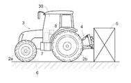
- the work vehicle is a tractor equipped with a work device that performs farm work such as tillage work on a farm field that is bounded by straw.
- a steering section 30 is formed at the center of the vehicle body 3 supported by the front wheels 2a and the rear wheels 2b.
- a ground working device 5 is provided at the rear of the vehicle body 3 via a hydraulic lifting mechanism 4.
- the front wheel 2a functions as a steered wheel, and the traveling direction of the tractor is changed by changing the steering angle.
- the steering angle of the front wheel 2 a is changed by the operation of the steering mechanism 6.
- the steering mechanism 6 is provided with a steering drive unit 60 (described later, see FIG.
- the steering unit 30 is also provided with a positioning unit 8 for measuring the position of the own aircraft that is necessary during the steering operation.
- the positioning unit 8 includes a satellite navigation module configured as a GNSS module and an inertial navigation module configured as a gyro module incorporating a gyro acceleration sensor and a magnetic bearing sensor.
- the satellite navigation module includes a satellite antenna for receiving GPS signals and GNSS signals, but is omitted in FIG.
- FIG. 3 shows a control system equipped in this work vehicle.
- This control system uses the basic principle of the automatic steering control described with reference to FIG.
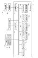
- the control system shown in FIG. 3 includes an electronic control unit 7, a positioning unit 8, a switch / sensor group 9, and a steering drive unit 60.
- the positioning unit 8 includes a satellite navigation module 81 that detects an orientation such as latitude and longitude using GNSS, and its configuration is similar to that of a positioning unit used in a car navigation system or the like.
- the positioning unit 8 includes an inertial navigation module 82 having a gyro acceleration sensor and the like in order to detect instantaneous work vehicle movement (direction vector and the like) and direction, and to complement the satellite navigation module 81. Is provided.
- the steering drive unit 60 adjusts the steering angle of the front wheels 2 a that are steered wheels based on the steering drive signal output from the electronic control unit 7.
- the switch / sensor group 9 is a general term for switches and sensors for detecting the traveling state and setting state of the work vehicle.
- the switch / sensor group 9 includes a sensor that outputs a detection signal for calculating the vehicle speed, and a sensor that outputs a detection signal for calculating the driving state (for example, operation speed and steering angle) of the steering drive unit 60. include.
- the electronic control unit 7 includes a reference route acquisition unit 71, a reference route setting unit 72, a vehicle position calculation unit 731, a vehicle direction calculation unit 732, a position deviation calculation unit 741, a direction, as functional units particularly related to the present invention.
- a deviation calculator 742, a first control calculator 751, a second control calculator 752, a target steering calculator 76, a vehicle speed calculator 78, and a steering drive controller 79 are included.
- the reference path acquisition unit 71 includes field information such as the map position of the farm field that is the work target and the position data of the ridge that defines the boundary line of the field, and device setting data relating to the field work to be performed (for example, work width) ) And the like, a target travel route for automatic steering work travel is acquired. Regarding acquisition of the target travel route, downloading from a remote management server, reading from the target travel route possessed by the work vehicle itself for each field and operation, etc. can be employed. You may calculate and obtain
- the target travel route may be calculated through teaching travel.
- the own vehicle position calculation unit 731 calculates the own vehicle position on the work travel map based on the positioning data sent from the positioning unit 8.
- the own vehicle direction calculation unit 732 calculates the traveling direction of the own vehicle on the work travel map based on the positioning data sent from the positioning unit 8.
- the position deviation calculation unit 741 calculates a position deviation (indicated by symbol d in FIG. 1) between the vehicle position relative to the target travel route.
- the azimuth deviation calculation unit 742 calculates an azimuth deviation (indicated by the symbol ⁇ in FIG. 1) between the azimuth line of the target travel route and the travel azimuth.
- the first control calculation unit 751 outputs the first steering value calculated for eliminating the deviation based on the position deviation.
- the second control calculation unit 752 reduces the weight of the azimuth deviation using the weighting coefficient as described above, and then performs the second control for eliminating the deviation based on the position deviation and the azimuth deviation.
- the steering value is output.
- the second control calculation unit 752 outputs a provisional second steering value for canceling the deviation based on the azimuth deviation, and reduces the provisional second steering value as the position deviation increases so that the formal second steering value is obtained. It may be configured to output as Note that the degree of reduction of the azimuth deviation depending on the magnitude of the position deviation can be adjusted or changed through the input device.
- the target steering calculation unit 76 outputs a target steering value for the work vehicle to travel along the target travel route based on the first steering value and the second steering value. In the simplest form, the addition calculation result of the first steering value and the second steering value becomes the target steering value.
- the target steering value output from the target steering calculation unit 76 is used as an input parameter in a control calculation for outputting a steering drive signal for driving the steering drive unit 60 in the steering drive control unit 79.
- the target steering calculation unit 76 considers the vehicle speed of the work vehicle obtained from the vehicle speed calculation unit 78 when calculating the target steering value, and if the vehicle speed is high, the target steering value and the second steering value are calculated. It also has a function of reducing the target steering value that is calculated and output based on the steering value. Specifically, when the target steering calculation unit 76 outputs the target steering value based on the first steering value and the second steering value, the target steering calculation unit 76 uses the adjustment coefficient k that shows a decreasing tendency as the vehicle speed increases. When the vehicle speed is high, the target steering value is reduced.
- a steering upper limit setting unit 760 is incorporated in the target steering calculation unit 76, and the steering upper limit setting unit 760 uses the first steering value, the second steering value, and further the target steering obtained using the vehicle speed.
- the value has a function of clamping the upper limit, that is, an upper limiter function. It is preferable that the upper limit value also varies depending on the vehicle speed. That is, the steering stability during high-speed traveling is improved by setting the maximum target steering value to be output as the vehicle speed increases.
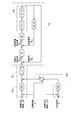
- the first control calculation unit 751 calculates and outputs a first steering value for reducing the position deviation: d using PI control with the target position deviation: ⁇ d and the position deviation: d as input parameters.
- PID control may be used instead of PI control.
- the second control calculation unit 752 calculates and outputs a temporary second steering value for reducing the azimuth deviation: ⁇ using PI control, with the target azimuth deviation: ⁇ and the azimuth deviation: ⁇ as input parameters.
- PID control may be used instead of PI control.
- the second control calculation unit 752 reduces the provisional second steering value obtained based on the azimuth deviation proportionally or nonlinearly according to the position deviation amount. And output as the second steering value.
- the target steering calculation unit 76 controls and outputs an addition value between the first steering value output from the first control calculation unit 751 and the second steering value output from the second control calculation unit 752 as a target steering value.
- the steering drive control unit 79 is configured as a feedback-type steering control module.
- the steering angle command value: S ⁇ * obtained by the comparison calculation with the actual steering angle: S ⁇ is input, and the preceding output value is obtained by using PI control.
- This previous stage output value is compared with the actual steering speed: S ⁇ output from the speed calculator: du / dt using differentiation, and the PI control is performed with the calculation result (steering speed command value: S ⁇ *) as an input.
- the steering drive signal drives a motor constituting the steering drive unit 60 via a driver to steer the front wheels 2a.
- the PI control in the steering drive control unit 79 may be replaced with PID control.
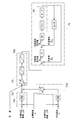
- FIG. 5 shows a modification of the control diagram of the electronic control unit 7 shown in FIG.
- the control diagram of FIG. 5 differs from FIG. 4 in that a function for reducing the target steering value that is finally output according to the vehicle speed is added to the target steering calculation unit 76. That is, in this modified example, the addition value of the first steering value output from the first control calculation unit 751 and the second steering value output from the second control calculation unit 752 is further increased as the vehicle speed increases. An arithmetic function for reducing the above is added.
- FIG. 6 shows a modification of the control diagram of the electronic control unit 7 shown in FIG.
- the control diagram of FIG. 6 is different from FIG. 5 in that a steering upper limit setting unit 760 is incorporated in the target steering calculation unit 76, and a function for clamping an upper limit of the target steering value that is finally output is added. Yes.
- the maximum target steering value output by the threshold value that changes according to the vehicle speed is suppressed before the obtained target steering value is output.
- the maximum target steering value that is output becomes smaller as the vehicle speed increases.
- the steering drive control unit 79 is configured as a steering control module that uses the actual steering angle and steering speed as feedback amounts.
- the control configuration of the steering drive control unit 79 is not limited, and other known control configurations may be employed.
- the target travel route is regarded as a straight line, but the present invention can be applied even if the target travel route is a curve.
- the positioning unit 8 is configured by the satellite navigation module 81 and the inertial navigation module 82, but may be configured by only the satellite navigation module 81.
- the tractor is exemplified as the automatic traveling work vehicle, but the present invention is not limited to this.
- the automatic traveling work vehicle may be another agricultural work vehicle such as a rice transplanter or a combine that is equipped with various working devices and is capable of automatic steering traveling. Further, the present invention is applicable not only to agricultural work vehicles but also to other work vehicles.
- Steering drive unit 76 Target steering calculation unit 78: Vehicle speed calculation unit 79: Steering drive control unit 731: Own vehicle position calculation unit 732: Own vehicle direction calculation unit 741: Position deviation calculation unit 742: Direction deviation calculation unit 751: 1st control calculating part 752: 2nd control calculating part
Landscapes
- Engineering & Computer Science (AREA)
- Mechanical Engineering (AREA)
- Life Sciences & Earth Sciences (AREA)
- Chemical & Material Sciences (AREA)
- Combustion & Propulsion (AREA)
- Transportation (AREA)
- Physics & Mathematics (AREA)
- Soil Sciences (AREA)
- Environmental Sciences (AREA)
- Mathematical Physics (AREA)
- Aviation & Aerospace Engineering (AREA)
- Radar, Positioning & Navigation (AREA)
- Remote Sensing (AREA)
- General Physics & Mathematics (AREA)
- Automation & Control Theory (AREA)
- Guiding Agricultural Machines (AREA)
- Steering Control In Accordance With Driving Conditions (AREA)
- Control Of Position, Course, Altitude, Or Attitude Of Moving Bodies (AREA)
Priority Applications (4)
| Application Number | Priority Date | Filing Date | Title |
|---|---|---|---|
| US16/099,892 US10602654B2 (en) | 2016-05-30 | 2016-05-30 | Auto traveling work vehicle |
| EP16903934.4A EP3467606B1 (de) | 2016-05-30 | 2016-05-30 | Autonomes arbeitsfahrzeug |
| CN201680085801.XA CN109154817B (zh) | 2016-05-30 | 2016-05-30 | 自动行驶作业车辆 |
| PCT/JP2016/065918 WO2017208306A1 (ja) | 2016-05-30 | 2016-05-30 | 自動走行作業車両 |
Applications Claiming Priority (1)
| Application Number | Priority Date | Filing Date | Title |
|---|---|---|---|
| PCT/JP2016/065918 WO2017208306A1 (ja) | 2016-05-30 | 2016-05-30 | 自動走行作業車両 |
Publications (1)
| Publication Number | Publication Date |
|---|---|
| WO2017208306A1 true WO2017208306A1 (ja) | 2017-12-07 |
Family
ID=60478207
Family Applications (1)
| Application Number | Title | Priority Date | Filing Date |
|---|---|---|---|
| PCT/JP2016/065918 Ceased WO2017208306A1 (ja) | 2016-05-30 | 2016-05-30 | 自動走行作業車両 |
Country Status (4)
| Country | Link |
|---|---|
| US (1) | US10602654B2 (de) |
| EP (1) | EP3467606B1 (de) |
| CN (1) | CN109154817B (de) |
| WO (1) | WO2017208306A1 (de) |
Cited By (6)
| Publication number | Priority date | Publication date | Assignee | Title |
|---|---|---|---|---|
| KR20200096500A (ko) * | 2017-12-18 | 2020-08-12 | 가부시끼 가이샤 구보다 | 자동 조타 시스템 및 자동 조타 방법 |
| CN113038821A (zh) * | 2018-10-30 | 2021-06-25 | 东京计器株式会社 | 误差修正装置 |
| WO2022107586A1 (ja) | 2020-11-18 | 2022-05-27 | 株式会社クボタ | 移動体、制御ユニット、および移動体の動作を制御する方法 |
| WO2022107588A1 (ja) | 2020-11-18 | 2022-05-27 | 株式会社クボタ | 移動体、制御ユニット、データ生成ユニット、移動体の動作を制御する方法、およびデータを生成する方法 |
| EP4019295A1 (de) | 2020-12-22 | 2022-06-29 | Kubota Corporation | Landwirtschaftliche maschine, sowie system und verfahren zur steuerung einer landwirtschaftlichen maschine |
| US12443198B2 (en) | 2020-11-18 | 2025-10-14 | Kubota Corporation | Mobile machine, data generation unit, and method of generating data |
Families Citing this family (16)
| Publication number | Priority date | Publication date | Assignee | Title |
|---|---|---|---|---|
| WO2019124298A1 (ja) * | 2017-12-18 | 2019-06-27 | 株式会社クボタ | 作業車及びトラクタ |
| CN111447826B (zh) * | 2018-01-23 | 2023-01-31 | 株式会社久保田 | 作业车辆 |
| US11154008B2 (en) * | 2018-08-20 | 2021-10-26 | Cnh Industrial America Llc | System and method for steering an agricultural harvester |
| US10696324B2 (en) * | 2018-10-15 | 2020-06-30 | Caterpillar Paving Products Inc. | Controlling machine operation including machine turning radius |
| CN109900273B (zh) * | 2019-02-28 | 2021-02-09 | 北京航天自动控制研究所 | 一种室外移动机器人导引方法及导引系统 |
| JP7346980B2 (ja) * | 2019-07-30 | 2023-09-20 | マツダ株式会社 | 車両制御システム |
| CN112384872B (zh) * | 2019-08-30 | 2024-02-27 | 深圳市大疆创新科技有限公司 | 可移动平台及其行驶控制方法和系统、控制设备 |
| JP7342541B2 (ja) * | 2019-09-06 | 2023-09-12 | オムロン株式会社 | ハウス管理システム、ハウス管理装置、ハウス管理方法及びプログラム |
| CN112650206A (zh) * | 2019-10-10 | 2021-04-13 | 苏州宝时得电动工具有限公司 | 智能割草机行走的控制方法及智能割草机 |
| US10935986B1 (en) * | 2019-11-28 | 2021-03-02 | Institute Of Automation, Chinese Academy Of Sciences | Gliding depth control method, system and device for biomimetic gliding robotic dolphin |
| JP7497669B2 (ja) * | 2020-10-28 | 2024-06-11 | 井関農機株式会社 | 自動制御コンバイン |
| CN112533143A (zh) * | 2020-12-02 | 2021-03-19 | 董树波 | 基于智能手机连接的地毯方向定位方法及其系统 |
| US12108696B2 (en) * | 2021-12-23 | 2024-10-08 | Cnh Industrial America Llc | Agricultural system and method for determining an as-driven path of an agricultural work vehicle |
| DE102022105922A1 (de) * | 2022-03-14 | 2023-09-14 | Krone Agriculture Se | Verfahren zur fahrroutenoptimierung |
| CN116022235B (zh) * | 2023-03-29 | 2023-06-16 | 北京理工大学深圳汽车研究院(电动车辆国家工程实验室深圳研究院) | 车辆转向控制方法、装置及车辆 |
| CN121180302B (zh) * | 2025-11-24 | 2026-02-03 | 厦门金龙联合汽车工业有限公司 | 一种港口重载igv液压制动转向分布式协同控制方法 |
Citations (3)
| Publication number | Priority date | Publication date | Assignee | Title |
|---|---|---|---|---|
| JPH05197423A (ja) * | 1992-01-17 | 1993-08-06 | Honda Motor Co Ltd | 移動体の制御装置 |
| JP2001350521A (ja) * | 2000-06-07 | 2001-12-21 | Nissan Motor Co Ltd | 車両の自動操舵装置 |
| JP2002333922A (ja) * | 2001-05-10 | 2002-11-22 | Isuzu Motors Ltd | 自動操舵装置 |
Family Cites Families (27)
| Publication number | Priority date | Publication date | Assignee | Title |
|---|---|---|---|---|
| JPS63153605A (ja) | 1986-12-17 | 1988-06-27 | Kubota Ltd | 自動走行作業車の操向制御装置 |
| JPH07223600A (ja) * | 1994-02-14 | 1995-08-22 | Mitsubishi Heavy Ind Ltd | 宇宙往還機の姿勢制御装置 |
| JP3281188B2 (ja) | 1994-08-09 | 2002-05-13 | ヤマハ発動機株式会社 | 無人車 |
| DE59805985D1 (de) * | 1997-06-28 | 2002-11-21 | Kostal Leopold Gmbh & Co Kg | Verfahren zum bestimmen der absoluten winkelstellung des lenkrades eines kraftfahrzeuges sowie optoelektronischer lenkwinkelsensor |
| JP3483855B2 (ja) | 2001-01-16 | 2004-01-06 | 川崎重工業株式会社 | 車両系の走行制御方法及び装置 |
| KR100580628B1 (ko) * | 2003-11-08 | 2006-05-16 | 삼성전자주식회사 | 이동물체의 진행방향 추정 방법 및 시스템 |
| JP2006268499A (ja) * | 2005-03-24 | 2006-10-05 | Funai Electric Co Ltd | 走行機および自走式掃除機。 |
| JP4195897B2 (ja) * | 2006-05-26 | 2008-12-17 | オリエンタルモーター株式会社 | ステッピングモータの制御装置 |
| JP2008131880A (ja) | 2006-11-28 | 2008-06-12 | Yanmar Co Ltd | 農用作業車 |
| JP4920393B2 (ja) | 2006-12-08 | 2012-04-18 | 本田技研工業株式会社 | 車両の操舵制御装置 |
| JP5045108B2 (ja) | 2007-01-11 | 2012-10-10 | トヨタ自動車株式会社 | 走行支援装置 |
| CN101118421A (zh) * | 2007-09-13 | 2008-02-06 | 北京航空航天大学 | 基于自适应蚁群智能的非线性pid控制参数整定方法 |
| JP5389360B2 (ja) | 2008-01-09 | 2014-01-15 | 富士重工業株式会社 | 車線追従制御装置および車線追従制御方法 |
| CN101221447A (zh) * | 2008-01-18 | 2008-07-16 | 中国农业大学 | 一种机械自动转向控制方法 |
| JP5359085B2 (ja) | 2008-03-04 | 2013-12-04 | 日産自動車株式会社 | 車線維持支援装置及び車線維持支援方法 |
| JP2010238217A (ja) * | 2009-03-09 | 2010-10-21 | Yaskawa Electric Corp | 移動ロボットの自己位置同定方法及び移動ロボット |
| US8510027B2 (en) * | 2009-06-11 | 2013-08-13 | Toyota Jidosha Kabushiki Kaisha | Method for judging vehicle traveling position and vehicle traveling position judgment device |
| JP2010152923A (ja) * | 2010-03-04 | 2010-07-08 | ▲吉▼川 英之 | リモートコントロール装置 |
| CN102147262A (zh) * | 2011-01-11 | 2011-08-10 | 北京理工大学 | 用于纠正导航偏差的方法、及采用该方法的导航显示器 |
| US9020757B2 (en) * | 2012-05-11 | 2015-04-28 | Trimble Navigation Limited | Path planning autopilot |
| JP5977203B2 (ja) * | 2012-12-21 | 2016-08-24 | 株式会社日本自動車部品総合研究所 | 車両制御装置 |
| CN105009160A (zh) * | 2013-09-04 | 2015-10-28 | 株式会社久保田 | 农业支援系统 |
| JP5939238B2 (ja) * | 2013-11-29 | 2016-06-22 | トヨタ自動車株式会社 | 車両用操舵制御装置 |
| CN103744428B (zh) * | 2014-01-17 | 2016-03-09 | 哈尔滨工程大学 | 一种基于邻域智能水滴算法的水面无人艇路径规划方法 |
| CN104536453B (zh) * | 2014-11-28 | 2017-08-04 | 深圳一电航空技术有限公司 | 飞行器的控制方法及装置 |
| CN104881025B (zh) * | 2015-04-10 | 2018-11-27 | 北京科技大学 | 一种地下矿用车辆的反应式导航控制方法 |
| CN105007012B (zh) * | 2015-07-16 | 2017-12-15 | 湖北三江航天万峰科技发展有限公司 | 一种车载转台控制系统及方法 |
-
2016
- 2016-05-30 EP EP16903934.4A patent/EP3467606B1/de active Active
- 2016-05-30 CN CN201680085801.XA patent/CN109154817B/zh active Active
- 2016-05-30 WO PCT/JP2016/065918 patent/WO2017208306A1/ja not_active Ceased
- 2016-05-30 US US16/099,892 patent/US10602654B2/en active Active
Patent Citations (3)
| Publication number | Priority date | Publication date | Assignee | Title |
|---|---|---|---|---|
| JPH05197423A (ja) * | 1992-01-17 | 1993-08-06 | Honda Motor Co Ltd | 移動体の制御装置 |
| JP2001350521A (ja) * | 2000-06-07 | 2001-12-21 | Nissan Motor Co Ltd | 車両の自動操舵装置 |
| JP2002333922A (ja) * | 2001-05-10 | 2002-11-22 | Isuzu Motors Ltd | 自動操舵装置 |
Non-Patent Citations (1)
| Title |
|---|
| See also references of EP3467606A4 * |
Cited By (14)
| Publication number | Priority date | Publication date | Assignee | Title |
|---|---|---|---|---|
| EP3729935A4 (de) * | 2017-12-18 | 2021-09-01 | Kubota Corporation | Automatisches lenksystem und automatisches lenkverfahren |
| US11317557B2 (en) | 2017-12-18 | 2022-05-03 | Kubota Corporation | Automatic steering system and automatic steering method |
| KR102871790B1 (ko) | 2017-12-18 | 2025-10-16 | 가부시끼 가이샤 구보다 | 자동 조타 시스템 및 자동 조타 방법 |
| KR20200096500A (ko) * | 2017-12-18 | 2020-08-12 | 가부시끼 가이샤 구보다 | 자동 조타 시스템 및 자동 조타 방법 |
| CN113038821B (zh) * | 2018-10-30 | 2022-12-06 | 东京计器株式会社 | 误差修正装置 |
| CN113038821A (zh) * | 2018-10-30 | 2021-06-25 | 东京计器株式会社 | 误差修正装置 |
| EP3874926A4 (de) * | 2018-10-30 | 2021-12-29 | Tokyo Keiki Inc. | Vorrichtung zur fehlerkorrektur |
| WO2022107588A1 (ja) | 2020-11-18 | 2022-05-27 | 株式会社クボタ | 移動体、制御ユニット、データ生成ユニット、移動体の動作を制御する方法、およびデータを生成する方法 |
| US12411493B2 (en) | 2020-11-18 | 2025-09-09 | Kubota Corporation | Mobile machine, control unit, and method of controlling operation of a mobile machine |
| US12443198B2 (en) | 2020-11-18 | 2025-10-14 | Kubota Corporation | Mobile machine, data generation unit, and method of generating data |
| WO2022107586A1 (ja) | 2020-11-18 | 2022-05-27 | 株式会社クボタ | 移動体、制御ユニット、および移動体の動作を制御する方法 |
| US12464964B2 (en) | 2020-11-18 | 2025-11-11 | Kubota Corporation | Mobile machine, control unit, data generation unit, method of controlling operation of a mobile machine, and method of generating data |
| EP4019295A1 (de) | 2020-12-22 | 2022-06-29 | Kubota Corporation | Landwirtschaftliche maschine, sowie system und verfahren zur steuerung einer landwirtschaftlichen maschine |
| US11917934B2 (en) | 2020-12-22 | 2024-03-05 | Kubota Corporation | Agricultural machine, and system and method for controlling agricultural machine |
Also Published As
| Publication number | Publication date |
|---|---|
| US20190133023A1 (en) | 2019-05-09 |
| CN109154817B (zh) | 2021-09-24 |
| CN109154817A (zh) | 2019-01-04 |
| EP3467606A4 (de) | 2020-01-29 |
| EP3467606B1 (de) | 2022-07-20 |
| EP3467606A1 (de) | 2019-04-10 |
| US10602654B2 (en) | 2020-03-31 |
Similar Documents
| Publication | Publication Date | Title |
|---|---|---|
| JP6420173B2 (ja) | 自動走行圃場作業車両 | |
| WO2017208306A1 (ja) | 自動走行作業車両 | |
| US11317557B2 (en) | Automatic steering system and automatic steering method | |
| US11052943B2 (en) | System and method for controlling a vehicle | |
| JP6528786B2 (ja) | 車両の運転支援装置 | |
| US10427712B2 (en) | Automatic driving system | |
| JP6437640B2 (ja) | 自律走行車の誘導制御システム | |
| US10401856B2 (en) | Vehicle travel control apparatus | |
| JP7072496B2 (ja) | 自動走行作業車のための制御装置 | |
| JP2020164160A (ja) | 自動走行圃場作業車両 | |
| JP2019038535A (ja) | 自動走行圃場作業車両 | |
| JP2019069745A (ja) | 運転支援制御システム | |
| CN107943060A (zh) | 一种自动驾驶仪、沿着跟踪直线引导车辆的方法以及计算机可读介质 | |
| US11603131B2 (en) | Control device and turning device | |
| KR20190009018A (ko) | 자율주행 농업기계의 작업안전을 위한 속도제어장치 및 방법 | |
| JP2020087340A (ja) | 自動走行作業車のための制御装置 | |
| WO2024118411A1 (en) | Steering angle error monitoring | |
| JP7316969B2 (ja) | 農作業用車両 | |
| JP7839377B2 (ja) | 制御方法、制御システム、自動制御車両 | |
| JP2005162153A (ja) | 操舵制御装置 | |
| JP2023046040A (ja) | 制御方法、制御システム、自動制御車両 | |
| JPH072131A (ja) | ヨーレート信号の調整方法 |
Legal Events
| Date | Code | Title | Description |
|---|---|---|---|
| 121 | Ep: the epo has been informed by wipo that ep was designated in this application |
Ref document number: 16903934 Country of ref document: EP Kind code of ref document: A1 |
|
| NENP | Non-entry into the national phase |
Ref country code: DE |
|
| ENP | Entry into the national phase |
Ref document number: 2016903934 Country of ref document: EP Effective date: 20190102 |
|
| NENP | Non-entry into the national phase |
Ref country code: JP |