WO2017208414A1 - コイル束誘導手段及びコイル挿入装置 - Google Patents
コイル束誘導手段及びコイル挿入装置 Download PDFInfo
- Publication number
- WO2017208414A1 WO2017208414A1 PCT/JP2016/066345 JP2016066345W WO2017208414A1 WO 2017208414 A1 WO2017208414 A1 WO 2017208414A1 JP 2016066345 W JP2016066345 W JP 2016066345W WO 2017208414 A1 WO2017208414 A1 WO 2017208414A1
- Authority
- WO
- WIPO (PCT)
- Prior art keywords
- coil
- coil bundle
- gap
- blade shaft
- bundle
- Prior art date
- Legal status (The legal status is an assumption and is not a legal conclusion. Google has not performed a legal analysis and makes no representation as to the accuracy of the status listed.)
- Ceased
Links
Images







Classifications
-
- H—ELECTRICITY
- H02—GENERATION; CONVERSION OR DISTRIBUTION OF ELECTRIC POWER
- H02K—DYNAMO-ELECTRIC MACHINES
- H02K15/00—Processes or apparatus specially adapted for manufacturing, assembling, maintaining or repairing of dynamo-electric machines
- H02K15/08—Forming windings by laying conductors into or around core parts
- H02K15/085—Forming windings by laying conductors into or around core parts by laying conductors into slotted stators
Definitions
- the present invention prevents the coil bundle from clogging in the middle of the gap when the coil bundle wound in advance by the winding frame is dropped to the base end of the gap formed by the blade shaft of the coil insertion device, thereby automating the stator manufacture.
- the present invention relates to a coil bundle guiding means and a coil insertion device to be made possible. More specifically, the coil bundle is not clogged in the middle of the gap, but is guided to the base end of the gap, and even if the coil bundle stagnates in the middle of the gap, the worker does not perform the work of loosening the coil bundle.
- the present invention relates to a coil bundle guiding means and a coil insertion device for guiding the coil bundle to the base end portion of the gap.
- the coil bundle previously wound around the winding frame by the winding machine is hooked on the tip of the blade shaft and dropped from the winding frame into the gap formed by each blade shaft.
- the coil bundle slides against the blade shaft, and is clogged in the gap formed by the blade shaft, and the blade shaft is pushed and expanded in the circumferential direction. If it does so, the blade axis
- Patent Document 1 before the coil bundle is hooked on the blade shaft, the coil bundles are aligned in advance so that they are stacked one by one, and the aligned coil bundle is dropped into the gap so that the coil bundle is less likely to be clogged in the gap. Techniques for making them disclosed are disclosed. According to Patent Document 1, a guide portion for aligning the windings is provided along the outer periphery of the winding shaft. Then, when the coil wire is passed through the alignment gap formed by the winding shaft and the guide portion to align the coil bundle, the aligned coil bundle is hooked on the tip of the blade shaft and dropped into the gap. Has been.
- Patent Document 2 discloses a coil insertion jig that prevents the arrangement of coil wires of a coil bundle from being scattered when the coil bundle is dropped into the gap from a winding machine.
- a coil guide that extends in parallel with the blade axis is provided and a coil receiving plate that can be moved up and down is provided so that the arrangement of the coil wires of the coil bundle is not scattered.
- the coil bundle hooked on the tip of the blade shaft has its lower edge part mounted on the coil receiving plate and is held by the coil guide, so that the coil insertion operation can be performed with the coil wires aligned. ing.
- Patent Document 3 discloses a technique for stabilizing the dropping of a coil bundle from a winding frame. According to the technique of Patent Document 3, a stepped shape in which the tip side of a blade operated integrally with the coil pusher is thinned, and the blade gap on the tip side is wider than the blade gap on the base end side, By doing so, it is said that dropping of the coil bundle can be stabilized.
- Patent Document 3 is a technique applied when the blade gap is in the range of 1 to 1.2 times the coil wire diameter. Then, similarly to Patent Document 1, the coil wire is inserted to increase the insertion density of the coil wire into the slot by shifting the center position of the coil wire to the left and right and dropping many coil wires into the gap formed by the blade shaft. It was not applicable to the device.
- Patent Document 4 discloses a technique of dropping a coil bundle from the top and bottom to the base end of the blade gap in a state where the coil wire is horizontally sandwiched so that the wound coil bundle does not clog the blade gap.
- the technique of Patent Document 4 when the wound coil bundle is once hooked on the transformer blade and transferred from the transformer blade to the blade shaft, the upper holding claw and the lower holding claw are used from the side. The blade is moved from the upper side to the lower side with the coil bundle interposed therebetween. Thus, the coil bundle is not inclined, the coil bundle is kept horizontal, and the coil wire is less likely to be clogged in the gap between the blade shafts.
- Patent Document 1 to Patent Document 4 it is only a technique for preventing the coil bundle from becoming clogged, and if the coil bundle is clogged in the gap formed by the blade shaft, It is necessary to loosen the coil bundle clogged up and guide it to the base end of the gap, making it difficult to automate the manufacture of the stator. Therefore, the inventor of the present application has made it a problem to provide a technique capable of automating the manufacture of a stator without requiring constant observation by an operator.
- Patent Document 1 Japanese Patent Laid-Open No. 2014-180129 Patent Document 2: Japanese Patent Laid-Open No. 7-194074 Patent Document 3: Japanese Patent Laid-Open No. 8-116650 Patent Document 4: Japanese Utility Model Laid-Open No. 5-15670
- the problem to be solved by the present invention is to prevent the coil bundle from clogging in the middle of the gap when the coil bundle wound in advance by the winding frame is dropped to the base end of the gap formed by the blade shaft of the coil insertion device. It is another object of the present invention to provide a coil bundle guiding means and a coil insertion device that enable automation of stator manufacture. More specifically, the coil bundle is not clogged in the middle of the gap, but is guided to the base end of the gap, and even if the coil bundle stagnates in the middle of the gap, the worker does not perform the work of loosening the coil bundle. However, it is to provide a coil bundle guiding means and a coil insertion device for guiding the coil bundle to the base end of the gap.
- the coil bundle guiding means of the first invention of the present invention is a coil insertion for inserting a coil bundle hooked in a gap formed by an annularly arranged blade shaft into a slot of a stator core held at the front portion of the blade shaft.
- Coil bundle guiding means provided in the apparatus wherein the coil bundle guiding means includes an opening end closing means and a sliding means, and the opening end closing means has the opening end closed in a state where the coil bundle is hooked.
- the gap is closed so that the gap width between the closing means and the blade shaft facing each other is smaller than the coil wire diameter, and the sliding means is adjacent to the coil bundle along the axial direction of the arranged blade shafts.
- One blade shaft of the matching blade shaft is slid with respect to the other blade shaft, and the coil bundle is dropped to the base end portion of the gap.
- the blade shaft that is slid by the sliding means may be provided by alternately providing movable blades and fixed blades, and the movable blades may be slid together, but is not limited thereto.
- three movable blades may be continuously arranged between the pair of fixed blades, and the central movable blade may be slid larger than the adjacent movable blades.
- shafts may be the height which corresponded, and may be different height.
- the sliding along the axial direction of the arranged blade shafts is not limited to the case where one blade shaft, that is, the movable blade is slid toward the base end portion of the gap, and the direction of the opening end of the gap Includes sliding into.
- the movable blade shaft may be slid directly from the original position toward the proximal end of the gap to induce the coil bundle.
- one blade shaft is slid with respect to the adjacent blade shaft sandwiching the coil bundle, so that the coil bundle is loosened and the coil bundle is dropped.
- the inserted resistance is reduced.
- the coil bundle can be It becomes easy to guide to the end.
- the coil bundle may be hooked in one blade gap so that the coil wires are stacked in a line.
- the coil bundle is guided smoothly, the pressure to the side of the blade shaft accompanying the induction of the coil bundle does not increase, and the blade shaft is not easily spread in the circumferential direction. Since the blade shaft does not tilt, the position of the front portion of the blade shaft does not shift. As a result, the stator core is unlikely to be held on the blade shaft by dropping the coil bundle.
- the movable blade may be moved at least when guiding the coil bundle to the base end of the gap, and may be fixed when inserting the coil bundle.
- the movable blade only needs to be able to hold the stator core in the distal portion after the coil bundle is guided to the proximal end portion of the gap, and may not be returned to the original position.
- the distance by which the movable blade is slid is not limited, and may be appropriately adjusted according to the wire diameter of the coil wire caught in the gap, the density of the coil wire, and the like. For example, when the density of the coil wire is high, the coil bundle is easily loosened when the sliding distance is increased.
- the gap width between the open end closing means and the blade shaft facing the coil end is smaller than the coil wire diameter, preventing the coil bundle from spilling out. If the coil bundle stagnates near the tip of the blade shaft, the coil wire does not spill out of the gap formed by the blade shaft even when the movable blade is slid toward the open end. Thereby, it is possible to prevent a part of the coil wire of the coil bundle from coming off from the tip end portion of the blade shaft and spilling out from the opening end of the gap.
- the method of hooking the coil bundle may be concentrated winding in which the coil bundle is hooked on one blade shaft, or distributed winding in which the coil bundle is hooked across a plurality of blade shafts, It is not limited.
- each coil bundle may be transferred directly from the winding machine to the gap between the blade shafts. Multiple coil bundles that are inserted simultaneously in the coil insertion operation are transferred to the blade shaft gap via a transfer jig. You may let them.
- the second invention of the present invention is the coil bundle guiding means according to the first invention, wherein the slide means is configured such that the one blade shaft can slide back and forth along the axial direction. It is characterized by.
- the manner in which the movable blade slides back and forth is not limited.
- the distance between “out” and “return” may be the same or different.
- different actions may be performed by combining the movements of “out”, “return”, and “stop”.
- the movable blade is slid in the distal direction and then slid again in the proximal direction, so that the stagnated coil bundle is loosened. . Therefore, the coil bundle can be guided to the base end portion of the gap without the worker performing the loosening operation. As a result, the coil bundle can be reliably guided to the position of the base end portion of the gap formed by the blade shaft.
- a third invention of the present invention is the coil bundle guiding means of the first or second invention, wherein the coil bundle guiding means includes inward pressing means, and the inward pressing means are arranged in the array. Along with the inner surface of the blade shaft, the coil bundle in the inner portion of the gap is pressed toward the base end portion in synchronization with the slide of the one blade shaft.
- the inward pressing means presses the coil bundle toward the base end of the gap so as to be synchronized with the slide of the movable blade.
- the inward pressing means and the movable blade may be synchronized as long as the sliding directions coincide with each other, and the speeds may not coincide.
- the coil bundle in the inner part of the gap is guided by the slide of the movable blade and also by the inward pressing means synchronized with the slide of the movable blade. As a result, the coil bundle can be reliably guided to the position of the base end portion of the gap formed by the blade shaft.
- the opening end closing means of the first invention may be slidable and may be an inward pressing means.
- the shape of the inward pressing means is not limited, and it may be a shaft body having a circular cross-sectional shape, and is provided with comb teeth protruding in the outer diameter direction like a stripper for inserting a coil bundle into a stator core. It is also good. When comb teeth are provided, it is preferable that a gap be formed between the comb teeth and each blade shaft. If the gap between the inner pressing means and each blade shaft is smaller than the wire diameter of the coil wire, the coil wire will not spill out of the inner pressing means.
- a fourth invention of the present invention is the coil bundle guiding means according to the third invention, wherein the coil bundle guiding means includes first alarm notification means, and the first alarm notification means is the inward pressing When the means detects that it is not slid in synchronization with the slide of the one blade shaft, an alarm is informed.
- Detecting means for detecting that the inward pressing means and the blade shaft are not synchronized is not limited.
- the sliding distance until the inward pressing means is stopped may be measured, or it may be detected whether the inward pressing means has reached a predetermined position. If the inward pressing means that is slid only by its own weight without being driven by the driving means stops in the middle of the blade shaft, an alarm may be informed that it is not synchronized with the movable blade shaft. Thereby, even if it is an inward pressing means slid only with its own weight, it can be confirmed whether the coil bundle is pressed down reliably.
- a fifth invention of the present invention is the coil bundle guiding means according to the first to fourth inventions, wherein the coil bundle guiding means includes outward pressing means, and the outward pressing means is outside the gap.
- the coil bundle is uniformly in contact with all the coil bundles extending in the direction, and the coil bundle is pressed toward the base end portion.
- the outward pressing means By providing an outward pressing means that uniformly contacts the coil bundle, when guiding the coil bundle to the base end, the coil bundle extending outward from the gap is also pressed along with the sliding of the blade shaft. Since the outward pressing means uniformly contacts all the coil bundles and presses the coil bundles, it is easier to guide the coil bundles so as not to tilt than when the coil bundles are sandwiched from above and below.
- the outward pressing means may be pressed from above by a driving force, or may be pressed only by its own weight. Thereby, it becomes easy to guide the coil bundle more reliably to the proximal end portion of the gap.
- a sixth invention of the present invention is the coil bundle guiding means according to the first to fifth inventions, wherein the slide means includes a slide distance changing means, and the slide distance changing means is provided on the one blade shaft. It is characterized by changing the slide distance.
- the slide distance changing means is not limited to this as long as the slide distance can be changed by changing the drive time of a servo motor or the like that slides the slide means. If the sliding distance of the blade shaft is increased, the time during which the frictional force between the coil wire and the blade shaft is reduced is increased, and the coil bundle is easily guided. Alternatively, the coil bundle may be guided by sliding the blade shaft in small increments and applying vibration to the coil bundle. Thereby, even when the wire diameter of the coil wire hooked on the blade shaft, the density of the coil wire, and the like are changed, the coil bundle can be guided more smoothly to the base end portion of the gap.
- a seventh invention of the present invention is the coil bundle guiding means according to the first to sixth inventions, wherein the coil bundle guiding means includes coil wire holding means, and the coil wire holding means holds the coil bundle. It is characterized in that each end of the formed coil wire is held. Each end of the coil wire refers to the start and end of the coil wire.
- the coil wire holding means only needs to be able to hook and hold the end of the coil wire, and the shape is not limited. For example, the end of the coil wire may be hooked on the hook-shaped claw.
- the end portion of the coil wire is held by the coil wire holding means, the end portion of the coil wire is not moved along with the slide of the movable blade when the coil bundle is guided to the base end portion of the gap. Thereby, even when the coil insertion device is automated from dropping of the coil bundle to insertion of the coil bundle, the end portions of the coil wires are not entangled with each other to cause a problem.
- the coil insertion device of the eighth invention of the present invention is characterized by comprising the coil bundle guiding means of the first to seventh inventions.
- the coil bundle is not clogged in the gap of the blade shaft, and the operator's observation is unnecessary. This makes it possible to provide a coil insertion device that automates stator manufacture from the stage of dropping the coil bundle.
- a coil insertion device is the coil insertion device according to the eighth aspect, wherein a core guide for aligning the blade shaft and the stator core when holding the stator core on the blade shaft;
- the core guide is slid along the inner side of the blade shaft arranged in an annular shape, and the second alarm notification means is configured so that the core guide forms the annular shape. It is characterized in that an alarm is informed when it is detected that the blade shafts arranged in are not slid and are not slid.
- Detecting means for detecting that the core guide is slid is not limited.
- the slide distance until the core guide is stopped may be measured, or it may be detected whether the core guide has reached a predetermined position. If the coil bundle is guided to the base end of the gap, the blade shaft does not tilt and the core guide is slid smoothly.
- the blade shaft is not inclined even after the blade shaft is moved to the position where the coil bundle is inserted into the stator core, and it is detected that the core guide is smoothly slid. Thereby, even at the stage of mounting the stator core, it is possible to promptly respond by alarm notification. As a result, even an automated coil insertion device from the stage of dropping the coil bundle to the mounting of the stator core can easily cope with unexpected situations.
- a coil bundle can be reliably guide
- a coil bundle can be reliably guide
- the coil bundle can be more reliably guided to the base end of the gap.
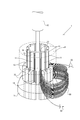
- the principal part perspective view of a coil bundle guidance means (Example 1).
- the principal part perspective view of a coil bundle guidance means (Example 1).
- the principal part perspective view of a coil bundle guidance means (Example 1).
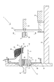
- Explanatory drawing by the cross section of a coil bundle guidance means (Example 1).
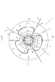
- the top view of a coil bundle guidance means (Example 1).
- Schematic plan view for explaining a coil insertion device Example 1).
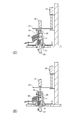
- Process drawing explaining the process of inducing a coil bundle (Example 1).
- Process drawing explaining the process of inducing a coil bundle (Example 1).
- Process drawing explaining the process of inducing a coil bundle (Example 1).
- Process drawing explaining the process of inducing a coil bundle (Example 1).
- Explanatory drawing explaining the state by which a coil bundle is loosened (Example 1).
- a coil bundle hooked on a blade shaft by sliding one blade shaft of adjacent blade shafts forming a gap to which the coil bundle is hooked along the axial direction of the arranged blade shafts with respect to the other blade shaft. was guided to the base end of the gap. By sliding one blade shaft in contact with the coil bundle, the frictional force applied to the coil bundle is reduced, and the coil bundle is guided so as not to be clogged with the gap.
- the coil bundle guiding means 1 including the movable blade 10 that is slidable and the inner pressing means 30 that is inserted into the inner space formed by the blade shaft is shown in FIGS.
- FIGS. 7 to 9 show only one coil bundle and omit the other coil bundles for easy understanding.
- FIG. 1 to FIG. 3 only the main part of the coil bundle guiding means 1 is shown.
- the broken line below the wedge guide and the base of the blade shaft is shown.
- the stripper 21 and the inward pressing means 30 are partially cut away and the movable blade 10 and the stripper 21 are colored.
- the inward pressing means 30 is indicated by a broken line.
- FIG. 1 shows a state where the coil bundle 60 is hooked on the blade shaft.
- FIG. 2 shows a state in which the inward pressing means 30 serving also as the opening end closing means is inserted into the inner side of the blade shaft and the movable blade 10 is slid upward.
- FIG. 3 shows a state after the coil bundle 60 is guided to the proximal end portion 14 of the gap.
- a state in which the stator core 24 is held at the tip of the blade shaft in a coil insertion process (see FIG. 14) that is a process different from the coil bundle induction process is indicated by a one-dot chain line.
- FIG. 4 is an explanatory diagram with a partially cutaway cross section at the AA position in FIG. 5, and FIG.
- FIG. 5 is a plan view at the BB position in FIG.
- FIG. 6 is a plan view illustrating the entire configuration of the coil insertion device 100.
- 7 to 9 are process diagrams illustrating a process of guiding the coil bundle 60 to the base end of the gap.
- FIG. 10 is an explanatory diagram for explaining a state where the coil bundle is loosened.
- the blade shaft is configured such that the movable blade 10 that is slidable and the fixed blade 11 that is fixed to the base 71 are alternately arranged in an annular shape (the movable blade 10 is colored in FIG. 1). ).
- Each movable blade 10 is integrated with a stripper 21 (see FIG. 4) for press-fitting a coil bundle into a slot of the stator core, and all the movable blades 10 and the stripper 21 are moved by a slide means 20 (see FIG. 4). It is possible to slide in conjunction (see FIG. 2).
- the slide means 20 is driven by a servo motor (not shown).
- the sliding means 20 and the stripper 21 are detachable.
- the sliding means 20 and the stripper 21 are locked by locking means (not shown), Slides together.
- the inner pressing means 30 includes a comb tooth portion 31 slightly smaller than the outer shape of the stripper 21 and a comb tooth portion 31 so as to be inserted into the inner space 15 formed by the blade shaft with a gap from the blade shaft.
- a gap 35 (see FIG. 5) between each blade shaft and the inward pressing means 30 is smaller than the wire diameter of the coil wire forming the coil bundle 60, and a part of the coil bundle hooked on the blade shaft is opened. It does not spill out of the gap from the end 17 (see FIG. 2). Further, since the gap 35 between the blade shaft and the inward pressing means 30 is provided, the inward pressing means 30 can be smoothly inserted into the inner space 15.
- the inward pressing means 30 can press the inner portion 64 (see FIG. 4) of the coil bundle located inward of the gap 13 in accordance with the slide of the movable blade 10.
- the pressing force by the inward pressing means 30 is not limited as long as the coil bundle 60 loosened by sliding the movable blade 10 can be slid along the inner surface of the blade shaft. For example, even if the pressing force is about the weight of the inward pressing means 30, if the coil bundle is loosened (see FIG. 10D), it can be easily guided to the base end portion 14 of the gap. (See FIG. 3).
- the advancing / retreating means 32 of the inward pressing means is synchronized with the slide of the movable blade 10 by a servo motor (not shown), and slides the inward pressing means 30 toward the base end portion 14 of the gap.
- the inward pressing means 30 is disposed on a slide base 33 that can be raised and lowered, and can be raised and lowered together with the slide base 33 by the raising and lowering means 34 (see FIG. 4).
- the elevating means 34 may be a known air cylinder or the like.
- each wedge guide 73 is provided along the outer surface of each blade shaft, and each wedge guide 73 is fixed to the base 71.
- the base 71 includes a disk-shaped substrate 72 extending in the horizontal direction from the outer periphery, and the same number of coil wire holding means 50 as the blade shafts are provided in the vicinity of the outer edge of the substrate 72 (see FIG. 5).
- the coil wire holding means 50 is provided with a hook-like portion 51 at the tip of the shaft body so that the end of the coil wire is hooked.
- the coil wire end portion refers to the start end portion 62 of the coil wire and the end portion 63 of the coil wire. For one coil bundle 60, each of the coil wire starting end 62 and terminal end 63 is hooked and held by two coil wire holding means 50 (see FIG. 5).
- the coil wire end In order to hook the coil wire end on the coil wire holding means 50, the coil wire end is kept in a state where the coil wire end is pinched by a cutter device (not shown) for cutting the coil wire after winding. What is necessary is just to move a part to the coil wire holding
- the upper tool 70 (see FIG. 4) includes a blade shaft including the movable blade 10 and the fixed blade 11, a stripper 21, a coil wire holding means 50, a base 71, and a wedge guide 73.
- the upper tool 70 is commonly used in any of the coil bundle guiding means 1, the winding means 101, and the coil inserting means 102 (see FIG. 6).
- the inward pressing means 30 and the slide base 33 are disposed on the fixed table 81 via the fixed shaft 36 and are used only in the coil bundle guiding means 1. Then, after the coil bundle 60 is guided to the base end portion 14 of the gap, the rotary table 80 is rotated, and the upper tool 70 is transferred to the coil insertion means 102 (position C in FIG. 6).
- FIG. 6 shows a schematic plan view of the coil insertion device 100.
- the coil bundle guiding means 1 which is the main configuration of the present invention is shown by a solid line, and the configurations of the winding means 101 (position in FIG. 6A) and the coil insertion means 102 (position in FIG. 6C) are broken lines. And a part of the configuration is omitted.
- the coil insertion device 100 includes a winding means 101, a coil bundle guiding means 1, a coil insertion means 102, and a table on which the upper tool 70 is placed.
- the table has a rotary table 80 on the outer side and a fixed table 81 on the inner side.
- the upper tool 70 is placed on the rotary table 80, and includes winding means 101 (position in FIG. 6A), coil bundle guiding means 1 (position in FIG. 6B), and coil insertion means 102 (position in FIG. 6C). They are transferred in order.
- the rotary table 80 is rotated, and the upper tool 70 is transferred to the first position (position A in FIG. 6A) where the winding means 101 is disposed.
- the starting end 62 of the coil wire is held by a cutter device (not shown) for cutting the coil wire and is hooked on the coil bundle holding means 50.
- the winding frame 103 is disposed immediately above a predetermined blade shaft, and a coil wire is wound around the winding frame 103 to form a coil bundle.
- Example 1 the terminal portion 63 of the coil wire is cut by the cutter device. Then, the terminal end 63 of the coil wire is held by the cutter device and hooked on the coil bundle holding means 50. Then, the coil bundle 60 is hooked on the tip of the blade shaft and dropped into the gap 13, whereby the coil bundle is transferred from the winding frame 103 to the blade shaft (see FIG. 1). This is repeated according to the number of coil bundles inserted into the stator core in one coil insertion step. In Example 1, the coil insertion process is divided into two times, and an example in which three bundles of coil bundles are inserted in one coil insertion process is shown (see FIGS. 5 and 6).
- the turntable 80 is rotated, and the upper tool 70 is transferred to the second position (position B in FIG. 6) where the coil bundle guiding means 1 performs the coil bundle guiding operation.
- the three coil bundles hooked on the blade shaft are guided to the proximal end portion 14 of the gap by the coil bundle guiding means 1 (see FIG. 3).
- the stripper 21 and the inward pressing means 30 are partially cut away in cross section, and the movable blade 10 and the stripper 21 are colored.
- the operation directions of the inward pressing means, the movable blade, and the stripper are indicated by arrows.
- FIG. 7A shows a state in which the coil bundle 60 is hooked on the blade shaft
- FIG. 7B shows the inner pressing means 30 inserted into the inner space 15 formed by the blade shaft.
- shaft makes is shown.
- FIG. 8C shows a state in which the movable blade 10 is extended toward the end of the gap.
- FIG. 8D shows a state where the movable blade 10 is slid toward the base end of the blade shaft gap and the coil bundle 60 is pressed by the inward pressing means 30.
- FIG. 9E shows a state where the coil bundle 60 is guided to the base end portion 14 of the gap
- FIG. 9F shows a state where the coil bundle induction process is completed.
- the rotary table 80 is rotated in a state where the coil bundle 60 is hooked on the blade shaft (see FIG. 1), and the upper tool 70 is transferred to the position where the coil bundle guiding means 1 is disposed. (See FIG. 7 (A), FIG. 6B position).
- the slide base 33 on which the inward pressing means 30 is arranged is lowered by the elevating means 34 (arrow in FIG. 7B), and the inward pressing means 30 is in the inner space 15. (See FIG. 7B). Since the inward pressing means 30 closes the opening end 17 (see FIG. 2) of the gap, a part of the coil bundle hooked on the tip end portion of the blade shaft is prevented from spilling out from the opening end 17.
- each movable blade 10 locked integrally with the stripper 21 is extended toward the tip of the blade shaft in the gap (arrow in FIG. 8C). Then, the slide means 20 and the advance / retreat means 32 are synchronized, and the movable blade 10 and the inward pressing means 30 are slid toward the proximal end portion 14 (see FIG. 1) of the gap, and the coil bundle 60 is guided. (FIG. 8 (D) diagram arrow).
- the movable blade 10 Since the movable blade 10 is slid toward the base end portion 14 of the gap, the frictional force at the portion where the coil bundle 60 and the movable blade 10 are in contact with each other is reduced. Further, since the coil bundle 60 is also pressed by the inward pressing means 30, the coil bundle 60 is smoothly guided to the proximal end portion 14 of the gap (FIG. 9E arrow).
- the first alarm notifying means (not shown).
- the detection means measures the slide distance until the inward pressing means 30 is stopped, and the position where the inward pressing means 30 is stopped is the reference position when the coil bundle is guided to the proximal end portion 14 of the gap. If the inner pressure means 30 has not been reached, it is determined that “the inner pressing means 30 is stopped during the slide, and the inner pressing means 30 and the movable blade 10 are not slid synchronously”, and an alarm is issued.
- the inward pressing means 30 is pulled out by the advancing / retreating means 32 from the inner space 15 formed by the blade shaft, and the slide base 33 is raised by the elevating means 34, and the inward pressing means. 30 returns to the original position (see the arrow in FIG. 9 (F)), and the coil bundle induction process is completed.
- FIG. 14 is an explanatory diagram for explaining the coil insertion means 102 in section.
- the movable blade 10 and the stripper 21 are colored for easy understanding.
- the stripper and the core guide are shown in a partially cutaway cross-sectional view, and the coil bundle 60, the wedge 23 and the wedge pusher 26 are shown only in one place.
- the outer edge of the stator core 24 is indicated by a one-dot chain line.
- 14A shows a state in which the core guide 25 is held at the tip of the blade shaft
- FIG. 14B shows a state in which the coil bundle 60 is inserted into the slot of the stator core 24. .
- the rotary table 80 is rotated, and the upper tool 70 is transferred to the third position (FIG. 6C position) where the coil insertion means 102 is disposed.
- the core guide 25 is inserted into the inner space 15 formed by the blade shaft, the stator core and the upper tool 70 are aligned in the horizontal direction, and the stator core 24 is attached to the tip of the blade shaft (see FIG. 14 (A)).
- the stripper 21 is stretched by the stretching means 22, the core guide 25 is retracted upward, the wedge pusher 26 for inserting the wedge 23 is stretched, and the coil bundle 60 and the wedge 23 are inserted into the stator core (see FIG. 14 (B)).
- the rotary table 80 is rotated again after the previous coil insertion process is completed, and the upper tool 70 is moved to the first position (FIG. 6-A position), the same winding process, coil bundle induction process, and coil insertion process are repeated, and the stator manufacture is completed.
- the second warning notification means measures the extension length of the core guide extension means 27, the extension length to the position where the slide of the core guide 25 is stopped, and the case where the core guide 25 is slid to the reference position. The stretch length is compared.
- an alarm is notified as “the core guide is not slid due to interference with the blade shaft”.
- reporting you may return to the induction
- FIG. 10 shows an enlarged view of the gap 13 formed by the adjacent movable blade 10 and the fixed blade 11.
- FIGS. 10B to 10E correspond to FIGS. 7B to 9E, respectively.
- the moving direction of the movable blade 10 and the inward pressing means 30 is shown by the arrow.
- FIG. 10B shows a state where the coil bundle 60 is stagnated in the gap 13 in the vicinity of the tip of the blade shaft.
- FIG. 10C shows a state in which the movable blade 10 is extended to loosen the coil bundle clogged in the gap 13.
- FIG. 10D shows a state in which the loosened coil bundle is guided toward the base end of the gap as the movable blade 10 slides.
- FIG. 10E shows a state in which the coil bundle is guided to the proximal end portion 14 of the gap.
- the inner pressing means 30 is inserted into the inner space 15 (see FIG. 4) formed by the blade shaft, and the opening end 17 of the gap formed by the blade shaft is closed (FIG. 10B). This prevents the coil bundle 60 from spilling out from the tip 16 of the blade shaft.
- the movable blade 10 is extended toward the tip of the blade shaft (see the arrow in FIG. 10C). When the movable blade is extended in a state where the coil bundle 60 is stagnated in the gap, the coil bundle 60 stagnated in the gap 13 is pulled up following the extension of the movable blade 10 (see FIG. 10C). ).
- the arrangement of the coil wires expands in the axial direction of the blade shaft compared to the state where the coil bundle is clogged, the state where the coil bundle is in close contact is loosened, and the coil bundle is easily induced (see FIG. (See FIG. 10 (C)).
- the movable blade 10 With the coil bundle 60 loosened, the movable blade 10 is slid toward the proximal end portion 14 of the gap, and the frictional force between the coil bundle 60 and the movable blade 10 is reduced.
- the inward pressing means 30 is slid in synchronization with the movable blade to press and guide the coil bundle 60 (see FIG. 10D).
- the coil bundle 60 can be smoothly guided to the base end portion 14 of the gap without clogging the gap 13 (see FIG. 10E and FIG. 3).
- the stator core 24 can be held without difficulty in the front portion of the blade shaft (see FIG. 3).
- Example 2 the coil bundle guiding means 2 provided with the sliding means 20, the inner pressing means 30, and the outer pressing means 40 will be described with reference to FIGS.
- the movable blade 10 and the stripper 21 are colored for easy understanding. Since the sliding means 20 and the inward pressing means 30 have the same configuration as that of the first embodiment, the same symbols are attached and description thereof is omitted.
- the second embodiment the case where the coil bundle hooked on the blade shaft is hooked on the blade shaft in a state where the coil wire density is higher than that in the first embodiment and the variation of the coil bundle is large will be described.
- the large variation of the coil bundle means a state in which the hooked coil bundle is dispersed in the axial direction of the blade shaft and the respective coil wires vary in the vertical direction.
- the outward pressing means 40 includes a pressing plate 41 for pressing the outer portion 65 (see FIG. 5) of the coil bundle extending outward from the gap 13, and an advancing / retreating means 42 for moving the pressing plate 41 back and forth (FIG. 11).
- the pressing plate 41 is formed with a through-hole 43 wider than the outer periphery of the wedge guide 73 so that the pressing plate 41 does not interfere with the wedge guide 73 in the center, and the planar shape is an annular shape.
- the pressing plate 41 is lowered from above with respect to the coil bundle, and presses uniformly against the outer portion 65 of all the coil bundles.
- the advance / retreat means 42 may be a known air cylinder or the like.
- the outward pressing means 40 presses the outer portion 65 of the coil bundle, the coil wires dispersed in the axial direction of the blade shaft become nearly horizontal. If it does so, since it will be in the state where a coil wire is easy to be induced, even if it is a case where there are many coil wires, a coil bundle can be smoothly guided to the base end part of a crevice.
- the outer pressing means 40 may be slid toward the base end of the gap as the inner pressing means 30 slides. Even if the outer pressing means is slid later than the sliding of the inner pressing means, the variation of the coil wire is reduced.
- FIG. 12C corresponds to the process of FIG. 8C
- FIG. 12E corresponds to the process of FIG. 9E.
- FIG. 12C shows a state where the slide base 33 is lowered and the movable blade 10 is extended.
- FIG. 12E shows a state in which the induction of the coil bundle 66 has been completed.
- the slide base 33 is lowered, and the inner pressing means 30 is inserted into the inner space 15 formed by the blade shaft to close the opening end 17 of the gap (see FIG. 2).
- the outer pressing means 40 is in contact with the outer portion 65 of the coil bundle (see FIG. 12C).
- the sliding means 20 slides the movable blade 10 toward the base end of the gap, moves the inward pressing means 30, and further moves the outward pressing means 40 so as to follow the inward pressing means 30.
- Lower see FIG. 12E. If it does so, it will be in the state where the upper part of the spread coil bundle 66 is near horizontal, ie, the coil bundle is hard to clog a gap, and is easy to guide. Thereby, even if the density of the coil wire is high and the variation of the hooked coil bundle becomes large, the coil bundle can be smoothly guided to the proximal end portion 14 of the gap (see FIG. 3).
- Example 3 the coil bundle guiding means 3 in which the movable blade 10 is slid back and forth when the sliding means guides the coil bundle will be described with reference to FIG.
- symbol is attached
- 13D corresponds to FIG. 10D
- FIG. 13E corresponds to FIG. 10E.
- Extending means of core guide, DESCRIPTION OF SYMBOLS 30 ... Inward pressing means, 31 ... Comb tooth part, 32 ... Advance / retreat means, 33 ... Slide base, 34 ... Elevating means, 35 ... Free fitting gap, 36 ... Fixed axis
Landscapes
- Engineering & Computer Science (AREA)
- Manufacturing & Machinery (AREA)
- Power Engineering (AREA)
- Manufacture Of Motors, Generators (AREA)
Abstract
【課題】コイル束を隙間の途中に詰まらせず、隙間の基端部まで誘導させると共に、仮にコイル束が隙間の途中に停滞した場合でも、作業員がコイル束のほぐし作業を行わなくても、コイル束を隙間の基端部まで誘導させるコイル束誘導手段及びコイル挿入装置を提供する。 【解決手段】 隙間に引っ掛けられたコイル束を隙間の基端部まで落とし込むコイル束誘導手段において、開口端閉塞手段とスライド手段とを含み、開口端閉塞手段は、コイル束が引っ掛けられた状態で、開口端閉塞手段と向かい合うブレード軸との隙間幅がコイル線径より小さい状態となるように隙間を塞ぎ、スライド手段は、軸方向に沿って、コイル束が接する隣り合うブレード軸の一方のブレード軸を他方のブレード軸に対してスライドさせて、コイル束を隙間の基端部まで落とし込ませるコイル束誘導手段、及びこれを含んだコイル挿入装置とした。
Description
本発明は、予め巻枠で巻回したコイル束を、コイル挿入装置のブレード軸がなす隙間の基端部まで落とし込む際に、コイル束が隙間の途中に詰まらないようにし、ステータ製造の自動化を可能にさせるコイル束誘導手段及びコイル挿入装置に関する。より詳細には、コイル束を隙間の途中に詰まらせず、隙間の基端部まで誘導させると共に、仮にコイル束が隙間の途中に停滞した場合でも、作業員がコイル束のほぐし作業を行わなくても、コイル束を隙間の基端部まで誘導させるコイル束誘導手段及びコイル挿入装置に関する。
コイル束をステータコアに挿入する前に、予め巻線機によって巻枠に巻回したコイル束を、ブレード軸の先端部に引っ掛けて、巻枠から夫々のブレード軸がなす隙間に落とし込んでいる。その際に、コイル束が傾いた状態になると、コイル束がブレード軸と摺り合って、ブレード軸がなす隙間の途中に詰まり、ブレード軸が周方向に押し拡げられるようになる。そうすると、ブレード軸が傾いて、ブレード軸の先端にステータコアを保持させることができなくなるという課題があった。
そのため、コイル束を巻枠からブレード軸の隙間に落とし込む際には、作業員が立ち会い、コイル束が詰まらないように常時看視していた。コイル束が前記隙間に詰まった場合には、一連のコイル落し込み作業を中断し、作業員が詰まったコイル束を一旦引き抜くように持ち上げて、詰まったコイル束のほぐし作業を行っていた。そして、ほぐしたコイル束を、隙間の基端部まで詰まらないように誘導させていた。ブレード軸に引っ掛けた全てのコイル束について、このコイル束の落とし込み作業を行ってから、ブレード軸の先方部にステータコアを保持させてコイル挿入作業が行われていた。
そこで、コイル束の落とし込み作業の効率化を図るために、コイル束をブレード軸の隙間に詰まりにくくする技術が提案されている。特許文献1には、コイル束をブレード軸に引っ掛ける前に、予めコイル線が1本ずつ積み重なるように整列させておき、整列させたコイル束を隙間に落とし込むことにより、コイル束を隙間に詰まりにくくさせる技術が開示されている。特許文献1によれば、巻回軸の外周に沿って、巻線を整列させる案内部を設けている。そして、巻回軸と案内部がなす整列隙間にコイル線を通過させて、コイル束を整列させた状態とし、整列されたコイル束がブレード軸の先端部に引っ掛けられ、隙間に落とし込まれるとされている。
しかし、特許文献1の技術によれば、コイル線を整列隙間に1本ずつ整列させる前に、コイル線を整列隙間の入口に落とし込むことが困難であった。また、コイル線を1本ずつ整然と並ぶように、予め積み重ねる技術であるため、ブレード隙間がコイル線の線径よりも広く、コイル線の中心位置が左右にずれるような状態に、コイル線を引っ掛ける場合には適用できなかった。したがって、コイル線の中心位置を左右にずらすようにして、ブレード軸がなす隙間に多くのコイル線を落とし込んでおき、スロットへのコイル線の挿入密度を高くさせるコイル挿入装置には適用できなかった。
特許文献2には、巻線機から前記隙間にコイル束を落とし込む際に、コイル束のコイル線の並びが散乱した状態とならないようにさせるコイル挿入治具が開示されている。特許文献2によれば、コイル束のコイル線の並びが散乱した状態とならないように、ブレード軸と平行に延びるコイルガイドを設けると共に、昇降可能なコイル受け板を設けるとされている。ブレード軸の先端部に引っ掛けられたコイル束は、下縁部分がコイル受け板に載ると共に、コイルガイドにより保持されるため、コイル線を整列させた状態でコイル挿入操作を行うことができるとされている。
しかし、特許文献2の技術によっても、特許文献1の技術と同様に、ブレード軸の先端部にコイル束を引っ掛けてから、ブレード軸の隙間にコイル線が整列されるまでの間に、コイル線がブレード軸の先端部で詰まる可能性があった。ブレード軸に加えて、コイルガイドにもコイル束を引っ掛ける必要があるため手間がかかるほか、コイル束を落とし込む際に、コイルガイドからコイル線が外れた場合には、コイル束を絡ませる可能性があった。
特許文献3には、巻枠からのコイル束の落とし込みの安定化を図る技術が開示されている。特許文献3の技術によれば、コイルプッシャーと一体に稼動されるブレードの先端側が細くなった段付き形状とされ、先端側のブレード隙間が、基端側のブレード隙間よりも広い段付き形状とされることにより、コイル束の落とし込みが安定化できるとされている。
しかし、特許文献3の技術は、ブレード隙間がコイル線径の1~1.2倍の範囲とされる場合に適用される技術とされている。そうすると、特許文献1と同様に、コイル線の中心位置を左右にずらすようにして、ブレード軸がなす隙間に多くのコイル線を落とし込んでおき、スロットへのコイル線の挿入密度を高くさせるコイル挿入装置には適用できなかった。
特許文献4には、巻回されたコイル束がブレード隙間に詰まらないように、上下からコイル線を水平に挟んだ状態で、ブレード隙間の基端部まで落とし込む技術が開示されている。特許文献4の技術によれば、巻回されたコイル束を一旦トランサブレードに引っ掛けておいて、トランサブレードからブレード軸に移し替える際に、側方から上側の把持爪と下側の保持爪で、コイル束を挟んだ状態として、ブレードの上方から下方に移動させている。これにより、コイル束が傾いた状態とならず、コイル束が水平に保たれ、ブレード軸の隙間にコイル線が詰まりにくくなるとされている。
しかし、特許文献4の技術によれば、全てのコイル束を一体に、側方から把持爪と保持爪とにより、上下から挟んだ状態として保持し、軸方向に沿ってブレード隙間の基端部までコイル束を誘導させている。そのため、把持爪又は保持爪に挟まれたコイル束が傾き易く、全てのコイル束を均一に保持することが困難であり、コイル線の整列状態が散乱される可能性があるという課題があった。
また、特許文献1から特許文献4のいずれの技術においても、コイル束が詰まりにくくなるように予防する技術に留まるものであり、ブレード軸がなす隙間にコイル束が詰まった場合には、作業員が詰まったコイル束をほぐして、前記隙間の基端部にまで誘導させる必要があり、ステータ製造を自動化させることは困難であった。そこで、本願の発明者は、作業員の常時看視を不要とし、ステータ製造を自動化できる技術を提供することを課題とした。
特許文献1:特開2014-180129号公報
特許文献2:特開平7-194074号公報
特許文献3:特開平8-116650号公報
特許文献4:実開平5-15670号公報
特許文献2:特開平7-194074号公報
特許文献3:特開平8-116650号公報
特許文献4:実開平5-15670号公報
本発明が解決しようとする課題は、予め巻枠で巻回したコイル束を、コイル挿入装置のブレード軸がなす隙間の基端部まで落とし込む際に、コイル束が隙間の途中に詰まらないようにし、ステータ製造の自動化を可能にさせるコイル束誘導手段及びコイル挿入装置を提供することである。より詳細には、コイル束を隙間の途中に詰まらせず、隙間の基端部まで誘導させると共に、仮にコイル束が隙間の途中に停滞した場合でも、作業員がコイル束のほぐし作業を行わなくても、コイル束を隙間の基端部まで誘導させるコイル束誘導手段及びコイル挿入装置を提供することである。
本発明の第1の発明のコイル束誘導手段は、環状に配列されたブレード軸がなす隙間に引っ掛けられたコイル束を、前記ブレード軸の先方部に保持させたステータコアのスロットに挿入させるコイル挿入装置に備えられるコイル束誘導手段であって、前記コイル束誘導手段は、開口端閉塞手段とスライド手段とを含み、前記開口端閉塞手段は、前記コイル束が引っ掛けられた状態で、前記開口端閉塞手段と向かい合うブレード軸との隙間幅がコイル線径より小さい状態となるように前記隙間を塞ぎ、前記スライド手段は、前記配列されたブレード軸の軸方向に沿って、前記コイル束が接する隣り合うブレード軸の一方のブレード軸を他方のブレード軸に対してスライドさせて、前記コイル束を前記隙間の基端部まで落とし込むことを特徴としている。
スライド手段によりスライドされるブレード軸は、可動ブレードと固定ブレードとを交互に設け、可動ブレードを一体にした状態でスライドさせればよいが、これに限定されない。例えば、対をなす固定ブレードの間に連続して3本の可動ブレードを配置し、中央の可動ブレードを両隣の可動ブレードよりも大きくスライドさせるようにしてもよい。なお、全てのブレード軸の先端部の原位置は、一致した高さであってもよく、異なった高さであってもよい。
配列されたブレード軸の軸方向に沿ってスライドされるとは、一方のブレード軸、すなわち可動ブレードが、隙間の基端部に向けてスライドされる場合に限定されず、隙間の開口端の方向にスライドされることを含んでいる。例えば、可動ブレードを、ブレード軸にコイル束を引っ掛けた原位置から開口端の方向にスライドさせた状態とし、その後隙間の基端部に向けてスライドさせるようにして、コイル束を誘導させてもよい。可動ブレード軸を、直接に原位置から隙間の基端部に向けてスライドさせ、コイル束を誘導させてもよいことは勿論のことである。
コイル束が接する隣り合うブレード軸のうち、一方のブレード軸が、コイル束を挟んでいる隣のブレード軸に対してスライドされるため、コイル束の挟まれている状態がゆるみ、コイル束が落とし込まれる抵抗が小さくなる。これにより、ひとつのブレード隙間に複数本のコイル線が並列された状態で引っ掛けられる場合や、コイル線の中心位置が左右にずれた状態で引っ掛けられる場合であっても、コイル束を隙間の基端部まで誘導させやすくなる。ひとつのブレード隙間に、コイル線が一列に積み上げられるようにコイル束が引っ掛けられてもよいことは勿論のことである。
仮に、コイル束が隙間の途中に停滞した場合であっても、一方のブレード軸が軸方向にスライドされることにより、隙間に停滞したコイル束がほぐされ、コイル束が誘導されやすい状態となる。これにより、作業員による常時看視と、コイル束が詰まった場合のほぐし作業が不要となり、コイル束の巻線から挿入までの一連のステータの製造工程の自動化が可能になるという有利な効果を奏する。
また、コイル束が滑らかに誘導され、コイル束の誘導に伴うブレード軸の側方への圧力が大きくならず、ブレード軸が周方向に押し広げられにくい。そして、ブレード軸が傾くことがないため、ブレード軸の先方部の位置がずれない。これにより、コイル束の落とし込みによって、ブレード軸にステータコアが保持できない状態となりにくい。
可動ブレードは、少なくともコイル束を隙間の基端部まで誘導させる際に可動されればよく、コイル束を挿入させる際には固定されていてもよい。可動ブレードは、コイル束を隙間の基端部まで誘導させた後に、先方部にステータコアを保持できればよく、原位置に復帰されなくてもよい。可動ブレードをスライドさせる距離は限定されず、隙間に引っ掛けられるコイル線の線径、コイル線の密度等に応じて適宜調整されればよい。例えば、コイル線の密度が高いような場合には、スライドさせる距離を長くするとコイル束がほぐれやすくなる。
開口端閉塞手段と向かい合うブレード軸との隙間幅は、コイル線径より小さくコイル束がこぼれ出ることが防止される。仮に、ブレード軸の先端近くでコイル束が停滞した場合において、可動ブレードを開口端に向けてスライドさせる場合であっても、ブレード軸がなす隙間からコイル線がこぼれ出ることはない。これにより、コイル束の一部のコイル線がブレード軸の先端部から外れて、隙間の開口端からこぼれ出ることを防止できる。
また、コイル束の引っ掛け方は、コイル束が一本のブレード軸に引っ掛けられる集中巻であってもよく、コイル束が複数本のブレード軸を跨ぐように引っ掛けられる分布巻であってもよく、限定されない。コイル束は、各々のコイル束を巻線機からブレード軸の隙間に直接移送させてもよく、コイル挿入作業で同時に挿入される複数のコイル束を、移送冶具を介してブレード軸の隙間に移送させてもよい。
本発明の第2の発明は、第1の発明のコイル束誘導手段であって、前記スライド手段は、前記一方のブレード軸が、前記軸方向に沿って往復してスライド可能とされていることを特徴としている。
可動ブレードが往復してスライドされる態様は限定されない。例えば、「往」と「復」の距離を同一としてもよく、異ならせてもよい。また、「往」と「復」と「停止」の動きを組み合わせて、異なった動作とさせてもよい。可動ブレードを複数回往復させることにより、確実にコイル束を隙間の基端部にまで誘導させることができる。
仮に、ブレード軸の途中にコイル束が停滞した状態となっても、可動ブレードが先端方向へスライドされて、再び基端方向へスライドされることにより、停滞した状態となったコイル束がほぐされる。そのため、作業員がほぐし作業を行わなくても、コイル束を隙間の基端部まで誘導させることができる。これにより、ブレード軸がなす隙間の基端部の位置まで、コイル束を確実に誘導させることができる。
本発明の第3の発明は、第1又は第2の発明のコイル束誘導手段であって、前記コイル束誘導手段が、内方押圧手段を含み、前記内方押圧手段は、前記配列されたブレード軸の内面に沿って、前記一方のブレード軸のスライドに同期するようにして、前記隙間の内方部にある前記コイル束を前記基端部に向けて押圧させることを特徴としている。
内方押圧手段は、可動ブレードのスライドに同期されるようにして、コイル束を隙間の基端部に向けて押圧させている。内方押圧手段と可動ブレードの同期は、スライド方向が一致していればよく、速度が一致していなくてもよい。隙間の内方部にあるコイル束が、可動ブレードのスライドにより誘導されると共に、可動ブレードのスライドに同期された内方押圧手段によっても誘導される。これにより、ブレード軸がなす隙間の基端部の位置まで、コイル束を確実に誘導させることができる。第1の発明の開口端閉塞手段をスライド可能とし、内方押圧手段としてもよい。
内方押圧手段の形状は限定されず、断面形状が円形形状の軸体とされてもよく、コイル束をステータコアに挿入させるストリッパと同様に、外径方向に突設された櫛歯が備えられたものとしてもよい。櫛歯を備えさせる場合には、櫛歯と各々のブレード軸との間に隙間があけられるようにするとよい。内方押圧手段と各々のブレード軸との隙間は、コイル線の線径よりも小さければ、コイル線が内方押圧手段の外にこぼれ出ることはない。
本発明の第4の発明は、第3の発明のコイル束誘導手段であって、前記コイル束誘導手段が、第1の警報報知手段を含み、第1の警報報知手段は、前記内方押圧手段が前記一方のブレード軸のスライドと同期してスライドされていないことを検知した場合に警報を報知させることを特徴としている。
内方押圧手段とブレード軸とが同期していないことを検知させる検知手段は限定されない。内方押圧手段が停止されるまでのスライド距離を計測してもよく、内方押圧手段が所定の位置に至ったかを検知するようにしてもよい。駆動手段に駆動されないで、自重だけでスライドされる内方押圧手段が、ブレード軸の途中に停止した場合には、可動ブレード軸と同期されていないとして警報を報知させればよい。これにより、自重だけでスライドされる内方押圧手段であっても、コイル束を確実に押し下げているかどうかを確認することができる。
本発明の第5の発明は、第1から第4の発明のコイル束誘導手段であって、前記コイル束誘導手段が、外方押圧手段を含み、前記外方押圧手段は、前記隙間から外方に伸びている全てのコイル束に均一に接して、前記コイル束を前記基端部に向けて押圧させることを特徴としている。
コイル束に均一に接する外方押圧手段が備えられることにより、コイル束を基端部まで誘導させる際に、ブレード軸のスライドに併せて、隙間から外方に伸びているコイル束も押圧させる。外方押圧手段は、全てのコイル束に均一に接して、コイル束を押圧させているため、コイル束を上下から挟む場合に比べて、コイル束を傾かないように誘導させやすい。外方押圧手段は、上方から駆動力により押圧させてもよく、自重のみで押圧させてもよい。これにより、コイル束を隙間の基端部まで、より確実に誘導させやすくなる。
本発明の第6の発明は、第1から第5の発明のコイル束誘導手段であって、前記スライド手段が、スライド距離変更手段を含み、前記スライド距離変更手段は、前記一方のブレード軸のスライド距離を変更させることを特徴としている。
スライド距離変更手段は、スライド手段をスライドさせるサーボモータ等の駆動時間を変更し、スライド距離を変更できればよいが、これに限定されない。ブレード軸のスライド距離を長くすれば、コイル線とブレード軸との間の摩擦力が小さくされる時間が長くなり、コイル束を誘導させやすくなる。また、ブレード軸を小刻みにスライドさせるようにし、コイル束に振動を与えるようにして、コイル束を誘導させるようにしてもよい。これにより、ブレード軸に引っ掛けられたコイル線の線径、コイル線の密度等が変更された場合であっても、コイル束をより滑らかに隙間の基端部まで誘導させることができる。
本発明の第7の発明は、第1から第6の発明のコイル束誘導手段であって、前記コイル束誘導手段が、コイル線保持手段を含み、前記コイル線保持手段が、前記コイル束をなすコイル線の各々の端部を保持させることを特徴としている。コイル線の各々の端部とは、コイル線の始端部と終端部を指している。コイル線保持手段は、コイル線の端部を引っ掛けて保持できればよく、形状は限定されない。例えば、鉤状の爪部にコイル線の端部が引っ掛けられればよい。
コイル線保持手段にコイル線の端部が保持されるため、コイル束を隙間の基端部まで誘導させる際に、コイル線の端部が可動ブレードのスライドに伴って移動されることがない。これにより、コイル束の落とし込みからコイル束の挿入までコイル挿入装置を自動化した場合でも、コイル線の端部が絡み合って不具合が発生されることがない。
本発明の第8の発明のコイル挿入装置は、第1から第7の発明のコイル束誘導手段を備えていることを特徴としている。コイル束の引っ掛け作業から挿入作業に亘る、いずれの工程においても、コイル束がブレード軸の隙間に詰まった状態とならず、作業員による看視が不要となる。これにより、コイル束の落とし込みの段階からステータ製造を自動化させたコイル挿入装置を提供することが可能となる。
本発明の第9の発明のコイル挿入装置は、第8の発明のコイル挿入装置であって、ブレード軸にステータコアを保持させる際に、ブレード軸とステータコアの位置合わせをするコアガイドと、第2の警報報知手段とを含み、前記コアガイドは、前記環状をなすように配列されたブレード軸の内方に沿ってスライドされ、第2の警報報知手段は、前記コアガイドが前記環状をなすように配列されたブレード軸に干渉し、スライドされていないことが検知された場合に警報を報知させることを特徴としている。
コアガイドがスライドされていることを検知させる検知手段は限定されない。コアガイドが停止されるまでのスライド距離を計測してもよく、コアガイドが所定の位置に至ったかを検知するようにしてもよい。コイル束が隙間の基端部まで誘導されていれば、ブレード軸が傾くことはなく、コアガイドも円滑にスライドされる。しかし、第10の発明では、ステータコアにコイル束が挿入される位置にブレード軸が移動された後にもブレード軸が傾いておらず、コアガイドが円滑にスライドされることを検知させている。これにより、ステータコアの装着の段階でも、警報の報知により速やかな対応を可能としている。これにより、コイル束の落とし込みの段階からステータコアの装着まで自動化したコイル挿入装置としても、不測の事態に対応しやすい。
・本発明の第1の発明によれば、ひとつのブレード隙間に複数本のコイル線が並列された状態で引っ掛けられる場合や、コイル線の中心位置が左右にずれた状態で引っ掛けられる場合であっても、コイル束を隙間の基端部まで誘導させやすくなる。これにより、作業員による常時看視と、コイル束が詰まった場合のほぐし作業が不要となり、コイル束の巻線から挿入までの一連のステータの製造工程の自動化が可能になるという有利な効果を奏する。また、コイル束の一部のコイル線がブレード軸の先端部から外れて、隙間の開口端からこぼれ出ることを防止できる。そして、コイル束の落とし込みによって、ブレード軸にステータコアが保持できない状態となりにくい。
・本発明の第2の発明によれば、ブレード軸がなす隙間の基端部の位置まで、コイル束を確実に誘導させることができる。
・本発明の第3の発明によれば、ブレード軸がなす隙間の基端部の位置まで、コイル束を確実に誘導させることができる。
・本発明の第4の発明によれば、自重だけでスライドされる内方押圧手段であっても、コイル束を確実に押し下げているかどうかを確認することができる。
・本発明の第5の発明によれば、コイル束を隙間の基端部まで、より確実に誘導させやすくなる。
・本発明の第3の発明によれば、ブレード軸がなす隙間の基端部の位置まで、コイル束を確実に誘導させることができる。
・本発明の第4の発明によれば、自重だけでスライドされる内方押圧手段であっても、コイル束を確実に押し下げているかどうかを確認することができる。
・本発明の第5の発明によれば、コイル束を隙間の基端部まで、より確実に誘導させやすくなる。
・本発明の第6の発明によれば、ブレード軸に引っ掛けられたコイル線の線径、コイル線の密度等が変更された場合であっても、コイル束をより滑らかに隙間の基端部まで誘導させることができる。
・本発明の第7の発明によれば、コイル束の落とし込みからコイル束の挿入までコイル挿入装置を自動化した場合でも、コイル線の端部が絡み合って不具合が発生されることがない。
・本発明の第8の発明によれば、コイル束の落とし込みの段階からステータ製造を自動化させたコイル挿入装置を提供することが可能となる。
・本発明の第9の発明によれば、コイル束の落とし込みの段階からステータコアの装着まで自動化したコイル挿入装置としても、不測の事態に対応しやすい。
・本発明の第7の発明によれば、コイル束の落とし込みからコイル束の挿入までコイル挿入装置を自動化した場合でも、コイル線の端部が絡み合って不具合が発生されることがない。
・本発明の第8の発明によれば、コイル束の落とし込みの段階からステータ製造を自動化させたコイル挿入装置を提供することが可能となる。
・本発明の第9の発明によれば、コイル束の落とし込みの段階からステータコアの装着まで自動化したコイル挿入装置としても、不測の事態に対応しやすい。
コイル束が引っ掛けられる隙間をなす隣り合うブレード軸の一方のブレード軸を、配列されたブレード軸の軸方向に沿って、他方のブレード軸に対してスライドさせて、ブレード軸に引っ掛けられたコイル束を隙間の基端部まで誘導させるようにした。コイル束に接する一方のブレード軸がスライドされることにより、コイル束にかかる摩擦力が小さくなり、コイル束が隙間に詰まらないように誘導される。
実施例1では、スライド可能とされた可動ブレード10と、ブレード軸がなす内方の空間に挿嵌される内方押圧手段30とを含んだコイル束誘導手段1を、図1から図10、及び図14を参照して説明する。なお、図1から図4及び図7から図9は、理解を容易にするため、ひとつのコイル束のみを示し、他のコイル束を省略している。図1から図3では、コイル束誘導手段1の要部のみを記載している。また、ウェッジガイドとブレード軸の基部より下方を破線で示している。図4では、ストリッパ21及び内方押圧手段30について一部切欠き断面を示し、可動ブレード10とストリッパ21とを着色している。図5では、内方押圧手段30を破線で示している。
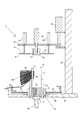
図1は、コイル束60をブレード軸に引っ掛けた状態を示している。図2は、開口端閉塞手段を兼ねた内方押圧手段30をブレード軸の内方に挿嵌させると共に、可動ブレード10を上方にスライドさせた状態を示している。図3は、コイル束60を隙間の基端部14まで誘導させた後の状態を示している。なお、図3では、コイル束の誘導工程とは別工程のコイル挿入工程(図14参照)において、ステータコア24がブレード軸の先方部に保持させた状態を一点鎖線で示している。図4は、図5のA-A位置の一部切欠き断面による説明図を示し、図5は、図4のB-B位置の平面図を示している。図6はコイル挿入装置100の全体構成を説明する平面図を示している。図7から図9はコイル束60を隙間の基端部まで誘導させる工程を説明する工程図である。図10はコイル束がほぐされる状態を説明する説明図である。
まず、図1から図5を参照して、コイル束誘導手段1の構成を説明する。ブレード軸は、スライド可能とされた可動ブレード10と、基台71に固定されている固定ブレード11とが交互に環状に配列されて構成されている(図1において可動ブレード10を着色している)。各々の可動ブレード10は、ステータコアのスロットにコイル束を圧入させるストリッパ21(図4参照)と一体とされており、スライド手段20(図4参照)により、全ての可動ブレード10とストリッパ21とが連動してスライド可能とされている(図2参照)。
スライド手段20は、サーボモータ(図示を省略している)により駆動される。スライド手段20とストリッパ21とは着脱可能とされており、可動ブレード10がスライドされる際には、スライド手段20とストリッパ21とが係止手段(図示を省略している)により係止され、一体にスライドされる。
内方押圧手段30は、ブレード軸がなす内方の空間15にブレード軸と隙間をあけて挿し込まれるように、ストリッパ21の外形よりも僅かに小さい櫛歯部31と、櫛歯部31を進退させる進退手段32とを備え、隙間閉塞手段を兼ねている(図4参照)。各々のブレード軸と内方押圧手段30との間の隙間35(図5参照)は、コイル束60をなすコイル線の線径よりも小さく、ブレード軸に引っ掛けられたコイル束の一部が開口端17(図2参照)から隙間の外にこぼれ出ないようにされている。また、ブレード軸と内方押圧手段30との間の隙間35が備えられるため、内方押圧手段30は円滑に内方の空間15に挿し込み可能とされている。
内方押圧手段30は、可動ブレード10のスライドに合わせて、隙間13よりも内方部にあるコイル束の内方部64(図4参照)を押圧可能とされている。内方押圧手段30による押圧力は、可動ブレード10をスライドさせることによりほぐされたコイル束60を、ブレード軸の内面に沿って滑らせることができればよい。例えば、内方押圧手段30の自重程度の押圧力であっても、ほぐされた状態のコイル束(図10(D)図参照)であれば、隙間の基端部14まで容易に誘導させることができる(図3参照)。
内方押圧手段の進退手段32は、サーボモータ(図示を省略している)により、可動ブレード10のスライドと同期され、内方押圧手段30を隙間の基端部14に向けてスライドさせる。また、内方押圧手段30は、昇降可能とされたスライドベース33に配設され、昇降手段34によりスライドベース33と共に昇降可能とされている(図4参照)。昇降手段34は、周知のエアシリンダー等であればよい。
また、各々のブレード軸の外面に沿うようにウェッジガイド73が備えられ、各々のウェッジガイド73は基台71に固定されている。基台71は、外周部から水平方向に広がる円盤状の基板72を備え、基板72の外縁近傍にはブレード軸と同数のコイル線保持手段50が備えられる(図5参照)。コイル線保持手段50は、軸体の先端部に鉤状部51が備えられ、コイル線端部が引っ掛けられるようにされている。コイル線端部とは、コイル線の始端部62と、コイル線の終端部63とを指している。ひとつのコイル束60について、コイル線の始端部62及び終端部63の各々が、2か所のコイル線保持手段50に引っ掛けられて保持される(図5参照)。
コイル線保持手段50に、コイル線端部を引っ掛けるには、巻線後にコイル線を裁断させるカッター装置(図示を省略している)でコイル線端部を摘まんだ状態のまま、コイル線端部をコイル線保持手段50にまで移動させ、鉤状部51(図11参照)に引っ掛ければよい。コイル線保持手段50にコイル線端部が引っ掛けられるため、コイル線端部がコイル束の誘導工程の際及びコイル挿入工程の際に、ブレード軸の軸方向に移動されることがなく、各々のコイル線端部が絡み合うことがない。また、コイル束をステータコアに挿入した後に、コイル線端部の処理を行う際も作業が容易となる。
アッパーツール70(図4参照)は、可動ブレード10及び固定ブレード11からなるブレード軸、ストリッパ21、コイル線保持手段50、基台71、ウェッジガイド73から構成される。アッパーツール70は、コイル束誘導手段1、巻線手段101及びコイル挿入手段102のいずれにおいても共通して使用される(図6参照)。内方押圧手段30及びスライドベース33は、固定軸36を介して固定テーブル81に配設され、コイル束誘導手段1においてのみ使用される。そして、コイル束60が隙間の基端部14まで誘導された後に、回転テーブル80が回転され、アッパーツール70がコイル挿入手段102まで移送される(図6-C位置)。
ここで、図6を参照してコイル挿入装置100の全体構成を簡単に説明する。図6はコイル挿入装置100の平面概略図を示している。図6では、本願発明の主要な構成であるコイル束誘導手段1について実線で示し、巻線手段101(図6-A位置)やコイル挿入手段102(図6-C位置)といった構成については破線で示すと共に、一部の構成を省略している。
コイル挿入装置100は、巻線手段101と、コイル束誘導手段1と、コイル挿入手段102と、アッパーツール70が載置されるテーブルとを含んでいる。テーブルは、外方が回転テーブル80とされ、内方が固定テーブル81とされている。アッパーツール70は、回転テーブル80に載置され、巻線手段101(図6-A位置)、コイル束誘導手段1(図6-B位置)、コイル挿入手段102(図6-C位置)の順に移送される。
まず、回転テーブル80が回転されて、巻線手段101が配設されている第1位置(図6-A位置)にアッパーツール70が移送される。次に、コイル線を切断するカッター装置(図示を省略している)によりコイル線の始端部62が摘ままれて、コイル束保持手段50に引っ掛けられる。そして、所定のブレード軸の直上位置に巻枠103を配置させ、巻枠103にコイル線を巻回させてコイル束が形成される。
次に、カッター装置によりコイル線の終端部63が切断される。そして、コイル線の終端部63がカッター装置に摘ままれて、コイル束保持手段50に引っ掛けられる。そして、コイル束60がブレード軸の先端部に引っ掛けられ、隙間13に落とし込まれることにより、巻枠103からブレード軸にコイル束が移送される(図1参照)。これが一回のコイル挿入工程においてステータコアに挿入されるコイル束の束数に応じて繰り返される。実施例1では、コイル挿入工程が2回に分割され、一回のコイル挿入工程において3束のコイル束が挿入される例を示している(図5,図6参照)。
巻線終了後に、回転テーブル80が回転されて、アッパーツール70がコイル束誘導手段1によりコイル束の誘導作業がされる第2位置(図6-B位置)に移送される。ここで、コイル束誘導手段1により、ブレード軸に引っ掛けられた3束のコイル束が隙間の基端部14にまで誘導される(図3参照)。
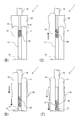
次に、図7から図9を参照して、コイル束60の誘導工程について説明する。図7から図9では、理解を容易にするため、ストリッパ21及び内方押圧手段30について一部切欠き断面を示し、可動ブレード10とストリッパ21とを着色している。また、内方押圧手段と可動ブレード及びストリッパの動作方向を矢印で示している。
図7(A)図は、コイル束60がブレード軸に引っ掛けられた状態を示し、図7(B)図は、ブレード軸がなす内方の空間15に、内方押圧手段30が挿し込まれ、ブレード軸がなす隙間を閉塞させた状態を示している。図8(C)図は、可動ブレード10が隙間の先方に向けて延伸された状態を示している。図8(D)図は、可動ブレード10がブレード軸の隙間の基端部に向けてスライドされると共に、コイル束60が内方押圧手段30に押圧されている状態を示している。図9(E)図は、コイル束60が隙間の基端部14まで誘導された状態を示し、図9(F)図は、コイル束の誘導工程が完了した状態を示している。
巻線工程が終了すると、ブレード軸にコイル束60が引っ掛けられた状態(図1参照)で、回転テーブル80が回転され、コイル束誘導手段1が配設されている位置までアッパーツール70が移送される(図7(A)図参照,図6-B位置)。コイル束の誘導工程では、まず、昇降手段34により内方押圧手段30の配設されたスライドベース33が降下(図7(B)図矢印)され、内方押圧手段30が内方の空間15に挿し込まれる(図7(B)図参照)。内方押圧手段30が隙間の開口端17(図2参照)を閉塞させるため、ブレード軸の先端部に引っ掛けられたコイル束の一部が開口端17から外にこぼれ出ることが防止される。
次に、スライド手段20が延伸されることにより、ストリッパ21と一体に係止された各々の可動ブレード10が隙間のブレード軸の先方に向けて延伸される(図8(C)図矢印)。そして、スライド手段20と進退手段32とが同期され、可動ブレード10と内方押圧手段30とが、隙間の基端部14(図1参照)に向けてスライドされ、コイル束60が誘導される(図8(D)図矢印)。
可動ブレード10が隙間の基端部14に向けてスライドされるため、コイル束60と可動ブレード10とが接している部分の摩擦力が小さくなる。さらに、コイル束60が内方押圧手段30によっても押圧されるため、コイル束60が隙間の基端部14まで滑らかに誘導される(図9(E)図矢印)。
ここで、内方押圧手段30と可動ブレード10とが同期されていないことが検知された場合には、第1の警報報知手段(図示を省略している)により警報が報知される。検知手段により、内方押圧手段30が停止されるまでのスライド距離を計測し、内方押圧手段30が停止された位置が、コイル束が隙間の基端部14まで誘導された場合の基準位置まで到達していない場合には、「内方押圧手段30がスライド途中に停止され、内方押圧手段30と可動ブレード10とが同期してスライドされていない。」と判定し警報を報知させる。
コイル束の誘導が終了された後に、ブレード軸がなす内方の空間15から、進退手段32により内方押圧手段30が引き抜かれると共に、昇降手段34によりスライドベース33が上昇され、内方押圧手段30が原位置に復帰し(図9(F)図矢印参照)、コイル束の誘導工程が終了される。
次に図6及び図14を参照して、コイル挿入作業について簡単に説明する。図14は、コイル挿入手段102を断面により説明する説明図である。図14では、理解を容易にするため可動ブレード10とストリッパ21を着色している。また、ストリッパ及びコアガイドを一部切欠断面図で示し、コイル束60、ウェッジ23及びウェッジプッシャ26を1か所のみ示している。また、ステータコア24の外縁を一点鎖線で示している。図14(A)図は、コアガイド25がブレード軸の先方部に保持された状態を示し、図14(B)図は、コイル束60がステータコア24のスロットに挿入された状態を示している。
コイル束の誘導工程が完了されると、回転テーブル80が回転され、コイル挿入手段102が配置されている第3位置(図6-C位置)にアッパーツール70が移送される。ここで、ブレード軸がなす内方の空間15にコアガイド25が挿し込まれ、ステータコアとアッパーツール70との水平方向の位置合わせがされ、ステータコア24がブレード軸の先端部に装着される(図14(A)図参照)。そして、ストリッパ21が延伸手段22により延伸されると共に、コアガイド25が上方に退避し、ウェッジ23を挿入させるウェッジプッシャ26が延伸され、コイル束60とウェッジ23とがステータコアに挿入される(図14(B)図参照)。
コイル束60は、2回のコイル挿入工程に分けてステータコアに挿入されるため、先のコイル挿入工程が終了された後、再び回転テーブル80が回転されて、アッパーツール70が第1位置(図6-A位置)まで移送され、同様の巻線工程、コイル束の誘導工程及びコイル挿入工程が繰り返され、ステータ製造が完了される。
また、コイル挿入工程(図14(A)図参照)において、コアガイド25がスライドされないことが検知された場合には、第2の警報報知手段(図示を省略している)により警報が報知される。第2の警報報知手段は、コアガイドの延伸手段27の延伸長さを計測し、コアガイド25のスライドが停止された位置までの延伸長さと、コアガイド25が基準位置までスライドされた場合の延伸長さを比較させている。そして、コアガイド25が基準位置まで到達していない場合には、「コアガイドがブレード軸と干渉してスライドされていない」として、警報が報知される。また、警報を報知させると共に、コイル束の誘導工程に戻って、コイル束の誘導工程を繰り返させてもよい。
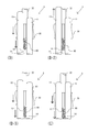
次に、図10を参照して、コイル束60が隙間13に停滞した場合に、コイル束60がほぐされる状態を詳細に説明する。図10の各々の図は隣り合う可動ブレード10と固定ブレード11とがなす隙間13の拡大図を示している。図10(B)図から図10(E)図は、それぞれの図が図7(B)図から図9(E)図に対応している。また、図10の各々の図において、可動ブレード10と内方押圧手段30の移動方向を矢印で示している。
図10(B)図は、ブレード軸の先端部近傍において、コイル束60が隙間13に停滞した状態を示している。図10(C)図は、可動ブレード10を延伸させて、隙間13に詰まったコイル束がほぐされる状態を示している。図10(D)図は、可動ブレード10のスライドに伴って、ほぐされたコイル束が隙間の基端部に向けて誘導されている状態を示している。図10(E)図は、コイル束が隙間の基端部14まで誘導された状態を示している。
まず、ブレード軸がなす内方の空間15(図4参照)に内方押圧手段30が挿し込まれ、ブレード軸がなす隙間の開口端17が閉塞される(図10(B)図)。これにより、コイル束60がブレード軸の先端部16から外にこぼれ出ることが防止される。次に、可動ブレード10がブレード軸の先方に向けて延伸される(図10(C)図矢印参照)。コイル束60が隙間に停滞した状態で、可動ブレードが延伸されると、隙間13に停滞していたコイル束60が、可動ブレード10の延伸に追従されて引き上げられる(図10(C)図参照)。
そうすると、コイル線の並びが、コイル束が詰まっていた状態と比べてブレード軸の軸方向に広がって、コイル束が密着していた状態がほぐされ、コイル束が誘導されやすい状態となる(図10(C)図参照)。コイル束60がほぐされた状態で、可動ブレード10が隙間の基端部14に向けてスライドされ、コイル束60と可動ブレード10との摩擦力が小さくされる。それと同時に、内方押圧手段30が可動ブレードに同期してスライドされ、コイル束60を押圧して誘導させる(図10(D)図参照)。
これにより、コイル束60を隙間13に詰まらせることなく、隙間の基端部14まで滑らかに誘導させることができる(図10(E)図,図3参照)。コイル束60が隙間の基端部14まで誘導されると、ブレード軸の先方部にステータコア24を無理なく保持させることができるようになる(図3参照)。
実施例2では、図11及び図12を参照して、スライド手段20、内方押圧手段30、外方押圧手段40が備えられたコイル束誘導手段2について説明する。また、図11及び図12では、理解を容易にするため、可動ブレード10とストリッパ21を着色している。スライド手段20、内方押圧手段30については、実施例1と同一の構成であるため、同一の記号を付して説明を省略している。なお、実施例2では、ブレード軸に引っ掛けられたコイル束が、実施例1の場合と比べてコイル線の密度が高く、コイル束のばらつきが大きい状態でブレード軸に引っ掛けられる場合を説明する。コイル束のばらつきが大きいとは、引っ掛けられたコイル束が、ブレード軸の軸方向に分散して、各々のコイル線が垂直方向にばらついた状態をいう。
外方押圧手段40は、隙間13から外方に伸びているコイル束の外方部65(図5参照)を押圧させるための押圧板41と、押圧板41を進退させる進退手段42(図11参照)とから構成されている。押圧板41は、中央にウェッジガイド73と干渉しないように、ウェッジガイド73の外周よりも広い貫通孔43が形成され、平面形状が円環形状とされている。この押圧板41は、コイル束に対して上方から下降され、全てのコイル束の外方部65に均一に接して押圧させる。進退手段42は、周知のエアシリンダー等とされればよい。
ブレード軸に引っ掛けられるコイル線の密度が高くなると、コイル束の外方部65のばらつきが大きくなることがある(図11参照)。外方押圧手段40がコイル束の外方部65を押圧させることにより、ブレード軸の軸方向に分散されたコイル線が水平に近い状態となる。そうすると、コイル線が誘導されやすい状態となるため、コイル線が多い場合であっても、コイル束を滑らかに隙間の基端部まで誘導させることができる。
なお、外方押圧手段40は、内方押圧手段30のスライドに伴って、隙間の基端部に向けてスライドされればよい。なお、内方押圧手段のスライドよりも遅れて外方押圧手段をスライドさせても、コイル線のばらつきが小さくなる。
次に、図12を参照して、コイル束の誘導工程について説明する。図12では理解を容易にするため、可動ブレード10とストリッパ21を着色している。また、内方押圧手段と可動ブレードのスライド方向を矢印で示している。なお、図12(C)図は、図8(C)図の工程に対応し、図12(E)図は、図9(E)図の工程に対応している。図12(C)図は、スライドベース33を降下させ、可動ブレード10を延伸させた状態を示している。図12(E)図は、コイル束66の誘導が終了された状態を示している。
まず、実施例1と同様に、スライドベース33が降下され、ブレード軸がなす内方の空間15に内方押圧手段30が挿し込まれ、隙間の開口端17を閉塞させる(図2参照)。コイル線のばらつきが大きい場合には、外方押圧手段40がコイル束の外方部65に接した状態となる(図12(C)図参照)。そして、スライド手段20により可動ブレード10を、隙間の基端部に向けてスライドさせると共に、内方押圧手段30を移動させ、更に内方押圧手段30に追従されるように外方押圧手段40を下降させる(図12(E)図参照)。そうすると、広がったコイル束66の上方部が水平に近い状態、すなわちコイル束が隙間に詰まりにくく、誘導させやすい状態となる。これにより、コイル線の密度が高く、引っ掛けられたコイル束のばらつきが大きくなった場合であっても、コイル束を滑らかに隙間の基端部14まで誘導させることができる(図3参照)。
実施例3では、図13を参照して、スライド手段がコイル束を誘導させる際に、可動ブレード10が往復スライドされるコイル束誘導手段3について説明する。実施例1と同一の構成については、同一の記号を付して説明を省略している。なお、図13(D)図は、図10(D)図に対応し、図13(E)図は図10(E)図に対応している。
可動ブレード10と内方押圧手段30とが、隙間の基端部に向けて同期してスライドされるまでの工程は、実施例1と同様である(図13(D)図参照)。次に、内方押圧手段30のスライドが一時停止され、可動ブレード10のみがスライド手段(図4参照)により、ブレード軸の先方に向けて再び延伸される(図13(D-2)図参照)。そして、可動ブレード10と内方押圧手段13とが、同期しながら隙間の基端部14に向けて再びスライドされる(図13(D-3)図参照)。
仮に、コイル束60を誘導させている途中に、コイル束が再度隙間13に停滞することがあっても、可動ブレード10を往復スライドさせることにより、コイル束60をほぐしてコイル束を誘導させやすい状態とすることができる。これにより、コイル束をなすコイル線の本数が多い場合であっても、コイル束60を隙間の基端部14まで、より滑らかに誘導させることができる(図13(E)図参照)。
(その他)
・本実施例では、分布巻の場合について説明しているが、集中巻に適用させてもよいことは勿論のことである。
・本実施例では、ストリッパと一体に一方のブレート軸をスライドさせているが、一方のブレード軸だけをスライドさせるようにしてもよい。
・今回開示された実施の形態はすべての点で例示であって、制限的なものではないと考えられるべきである。本発明の技術的範囲は、上記した説明に限られず特許請求の範囲によって示され、特許請求の範囲と均等の意味及び範囲内でのすべての変更が含まれることが意図される。
・本実施例では、分布巻の場合について説明しているが、集中巻に適用させてもよいことは勿論のことである。
・本実施例では、ストリッパと一体に一方のブレート軸をスライドさせているが、一方のブレード軸だけをスライドさせるようにしてもよい。
・今回開示された実施の形態はすべての点で例示であって、制限的なものではないと考えられるべきである。本発明の技術的範囲は、上記した説明に限られず特許請求の範囲によって示され、特許請求の範囲と均等の意味及び範囲内でのすべての変更が含まれることが意図される。
1,2,3…コイル束誘導手段、
100…コイル挿入装置、101…巻線手段、102…コイル挿入手段、103…巻枠、
10…可動ブレード、11…固定ブレード、13…隙間、14…隙間の基端部、15…内方の空間、16…ブレード軸の先端部、17…開口端、
20…スライド手段、21…ストリッパ、22…延伸手段、23…ウェッジ、24…ステータコア、25…コアガイド、26…ウェッジプッシャ、27…コアガイドの延伸手段、
30…内方押圧手段、31…櫛歯部、32…進退手段、33…スライドベース、34…昇降手段、35…遊嵌隙間、36…固定軸、
40…外方押圧手段、41…押圧板、42…進退手段、43…貫通孔、
50…コイル束保持手段、51…鉤状部、
60,66…コイル束、62…始端部、63…終端部、64…内方部、65…外方部、
70…アッパーツール、71…基台、72…基板、73…ウェッジガイド、
80…回転テーブル、81…固定テーブル
100…コイル挿入装置、101…巻線手段、102…コイル挿入手段、103…巻枠、
10…可動ブレード、11…固定ブレード、13…隙間、14…隙間の基端部、15…内方の空間、16…ブレード軸の先端部、17…開口端、
20…スライド手段、21…ストリッパ、22…延伸手段、23…ウェッジ、24…ステータコア、25…コアガイド、26…ウェッジプッシャ、27…コアガイドの延伸手段、
30…内方押圧手段、31…櫛歯部、32…進退手段、33…スライドベース、34…昇降手段、35…遊嵌隙間、36…固定軸、
40…外方押圧手段、41…押圧板、42…進退手段、43…貫通孔、
50…コイル束保持手段、51…鉤状部、
60,66…コイル束、62…始端部、63…終端部、64…内方部、65…外方部、
70…アッパーツール、71…基台、72…基板、73…ウェッジガイド、
80…回転テーブル、81…固定テーブル
Claims (9)
- 環状に配列されたブレード軸がなす隙間に引っ掛けられたコイル束を、前記ブレード軸の先方部に保持させたステータコアのスロットに挿入させるコイル挿入装置に備えられるコイル束誘導手段であって、
前記コイル束誘導手段は、開口端閉塞手段とスライド手段とを含み、
前記開口端閉塞手段は、前記コイル束が引っ掛けられた状態で、前記開口端閉塞手段と向かい合うブレード軸との隙間幅がコイル線径より小さい状態となるように前記隙間を塞ぎ、
前記スライド手段は、前記配列されたブレード軸の軸方向に沿って、前記コイル束が接する隣り合うブレード軸の一方のブレード軸を他方のブレード軸に対してスライドさせて、前記コイル束を前記隙間の基端部まで落とし込む、
ことを特徴とするコイル束誘導手段。 - 前記スライド手段は、前記一方のブレード軸が、前記軸方向に沿って往復してスライド可能とされていることを特徴とする請求項1に記載のコイル束誘導手段。
- 前記コイル束誘導手段が、内方押圧手段を含み、
前記内方押圧手段は、前記配列されたブレード軸の内面に沿って、前記一方のブレード軸のスライドに同期するようにして、前記隙間の内方部にある前記コイル束を前記基端部に向けて押圧させる、
ことを特徴とする請求項1又は請求項2に記載のコイル束誘導手段。 - 前記コイル束誘導手段が、第1の警報報知手段を含み、
第1の警報報知手段は、前記内方押圧手段が前記一方のブレード軸のスライドと同期してスライドされていないことを検知した場合に警報を報知させる、
ことを特徴とする請求項3に記載のコイル束誘導手段。 - 前記コイル束誘導手段が、外方押圧手段を含み、
前記外方押圧手段は、前記隙間から外方に伸びている全てのコイル束に均一に接して、前記コイル束を前記基端部に向けて押圧させる、
ことを特徴とする請求項1乃至請求項4のいずれか一項に記載のコイル束誘導手段。 - 前記スライド手段が、スライド距離変更手段を含み、
前記スライド距離変更手段は、前記一方のブレード軸のスライド距離を変更させる、
ことを特徴とする請求項1乃至請求項5のいずれか一項に記載のコイル束誘導手段。 - 前記コイル束誘導手段が、コイル線保持手段を含み、
前記コイル線保持手段が、前記コイル束をなすコイル線の各々の端部を保持させる、
ことを特徴とする請求項1乃至請求項6のいずれか一項に記載のコイル束誘導手段。 - コイル挿入装置であって、請求項1乃至請求項7のいずれか一項に記載のコイル束誘導手段を備えている、
ことを特徴とするコイル挿入装置。 - 請求項8に記載のコイル挿入装置であって、
ブレード軸にステータコアを保持させる際に、ブレード軸とステータコアの位置合わせをするコアガイドと、第2の警報報知手段とを含み、
前記コアガイドは、前記環状をなすように配列されたブレード軸の内方に沿ってスライドされ、
第2の警報報知手段は、前記コアガイドが前記環状をなすように配列されたブレード軸に干渉し、スライドされていないことが検知された場合に警報を報知させる、
ことを特徴とするコイル挿入装置。
Priority Applications (3)
| Application Number | Priority Date | Filing Date | Title |
|---|---|---|---|
| CN201680083542.7A CN109314448B (zh) | 2016-06-02 | 2016-06-02 | 线圈束引导单元以及线圈插入装置 |
| JP2016555793A JP6045052B1 (ja) | 2016-06-02 | 2016-06-02 | コイル束誘導手段及びコイル挿入装置 |
| PCT/JP2016/066345 WO2017208414A1 (ja) | 2016-06-02 | 2016-06-02 | コイル束誘導手段及びコイル挿入装置 |
Applications Claiming Priority (1)
| Application Number | Priority Date | Filing Date | Title |
|---|---|---|---|
| PCT/JP2016/066345 WO2017208414A1 (ja) | 2016-06-02 | 2016-06-02 | コイル束誘導手段及びコイル挿入装置 |
Publications (1)
| Publication Number | Publication Date |
|---|---|
| WO2017208414A1 true WO2017208414A1 (ja) | 2017-12-07 |
Family
ID=57543844
Family Applications (1)
| Application Number | Title | Priority Date | Filing Date |
|---|---|---|---|
| PCT/JP2016/066345 Ceased WO2017208414A1 (ja) | 2016-06-02 | 2016-06-02 | コイル束誘導手段及びコイル挿入装置 |
Country Status (3)
| Country | Link |
|---|---|
| JP (1) | JP6045052B1 (ja) |
| CN (1) | CN109314448B (ja) |
| WO (1) | WO2017208414A1 (ja) |
Families Citing this family (2)
| Publication number | Priority date | Publication date | Assignee | Title |
|---|---|---|---|---|
| JP7487676B2 (ja) * | 2021-01-29 | 2024-05-21 | ニデック株式会社 | コイル挿入装置 |
| JP2022156296A (ja) * | 2021-03-31 | 2022-10-14 | 日本電産株式会社 | コイル挿入装置 |
Citations (6)
| Publication number | Priority date | Publication date | Assignee | Title |
|---|---|---|---|---|
| JPS61109442A (ja) * | 1984-11-02 | 1986-05-27 | Hitachi Ltd | コイル插入装置 |
| JPS61244246A (ja) * | 1985-04-18 | 1986-10-30 | Sanko Kiki Kk | コイル挿入装置 |
| JPH07308052A (ja) * | 1994-05-12 | 1995-11-21 | Odawara Eng:Kk | コイル挿入装置 |
| JPH10174380A (ja) * | 1996-12-11 | 1998-06-26 | Hitachi Ltd | コイル挿入方法及び同装置 |
| JP2005080356A (ja) * | 2003-08-29 | 2005-03-24 | Honda Motor Co Ltd | コイル挿入方法 |
| JP2010259215A (ja) * | 2009-04-24 | 2010-11-11 | Toyota Motor Corp | ステータ製造方法、及びステータ製造装置 |
Family Cites Families (3)
| Publication number | Priority date | Publication date | Assignee | Title |
|---|---|---|---|---|
| US4026009A (en) * | 1976-03-11 | 1977-05-31 | General Electric Company | Apparatus and methods for aligning and placing insulating members in magnetic core slots |
| JP5046754B2 (ja) * | 2007-06-22 | 2012-10-10 | 三工機器株式会社 | コイル挿入装置 |
| JP5795148B2 (ja) * | 2010-02-26 | 2015-10-14 | E−Tec株式会社 | コイル挿入装置 |
-
2016
- 2016-06-02 JP JP2016555793A patent/JP6045052B1/ja not_active Expired - Fee Related
- 2016-06-02 CN CN201680083542.7A patent/CN109314448B/zh not_active Expired - Fee Related
- 2016-06-02 WO PCT/JP2016/066345 patent/WO2017208414A1/ja not_active Ceased
Patent Citations (6)
| Publication number | Priority date | Publication date | Assignee | Title |
|---|---|---|---|---|
| JPS61109442A (ja) * | 1984-11-02 | 1986-05-27 | Hitachi Ltd | コイル插入装置 |
| JPS61244246A (ja) * | 1985-04-18 | 1986-10-30 | Sanko Kiki Kk | コイル挿入装置 |
| JPH07308052A (ja) * | 1994-05-12 | 1995-11-21 | Odawara Eng:Kk | コイル挿入装置 |
| JPH10174380A (ja) * | 1996-12-11 | 1998-06-26 | Hitachi Ltd | コイル挿入方法及び同装置 |
| JP2005080356A (ja) * | 2003-08-29 | 2005-03-24 | Honda Motor Co Ltd | コイル挿入方法 |
| JP2010259215A (ja) * | 2009-04-24 | 2010-11-11 | Toyota Motor Corp | ステータ製造方法、及びステータ製造装置 |
Also Published As
| Publication number | Publication date |
|---|---|
| JPWO2017208414A1 (ja) | 2018-06-21 |
| CN109314448B (zh) | 2020-06-19 |
| CN109314448A (zh) | 2019-02-05 |
| JP6045052B1 (ja) | 2016-12-14 |
Similar Documents
| Publication | Publication Date | Title |
|---|---|---|
| JP5795148B2 (ja) | コイル挿入装置 | |
| US10396638B2 (en) | Stator manufacturing apparatus and stator manufacturing method | |
| JP6045052B1 (ja) | コイル束誘導手段及びコイル挿入装置 | |
| US20160156240A1 (en) | Stator winding for rotary electric machine, stator for rotary electric machine, method of manufacturing stator for rotary electric machine, and jig used in manufacturing stator for rotary electric machine | |
| WO2015132895A1 (ja) | コイル挿入機 | |
| EP3576264A1 (en) | Method for manufacturing laminated iron core and device for manufacturing laminated iron core | |
| JPWO2015111096A1 (ja) | 積層鉄心製造装置および積層鉄心の製造方法 | |
| KR101640239B1 (ko) | 코일 삽입기 | |
| US4723354A (en) | Apparatus and method for transferring coil leads from a partially assembled stator to a lead finishing assembly | |
| JP2007089310A (ja) | コイルの挿入方法及び装置 | |
| EP0203257A2 (en) | Method and apparatus for positioning and transferring stator coil leads | |
| CN112186983A (zh) | 线圈分离方法及线圈分离装置 | |
| JP2017063529A (ja) | コイル挿入方法及びコイル挿入装置 | |
| JP4872475B2 (ja) | ステータコイルのセット方法及びセット装置、並びに回転電機の製造方法 | |
| JP5943522B2 (ja) | ウェッジメイク装置及びコイル挿入装置 | |
| IE42026B1 (en) | Improvements in or relating to the securing of the tail ends of yarn bobbins | |
| KR101562858B1 (ko) | 브러시 세트 자동제조장치 | |
| TWI817341B (zh) | 線圈插入裝置 | |
| US7267296B2 (en) | Method and apparatus for winding multi-pole stators with termination hooks | |
| JP2002033235A (ja) | 巻線装置 | |
| DE102018222751A1 (de) | Stator für einen Elektromotor | |
| JP2002199673A (ja) | ステータ巻線方法及びステータ巻線機 | |
| JP5453854B2 (ja) | コイル形成挿入装置 | |
| CN121755618A (zh) | 一种线束屏蔽丝裁切装置及方法 | |
| CN113746283A (zh) | 线圈束成形装置 |
Legal Events
| Date | Code | Title | Description |
|---|---|---|---|
| ENP | Entry into the national phase |
Ref document number: 2016555793 Country of ref document: JP Kind code of ref document: A |
|
| NENP | Non-entry into the national phase |
Ref country code: DE |
|
| 121 | Ep: the epo has been informed by wipo that ep was designated in this application |
Ref document number: 16904039 Country of ref document: EP Kind code of ref document: A1 |
|
| 122 | Ep: pct application non-entry in european phase |
Ref document number: 16904039 Country of ref document: EP Kind code of ref document: A1 |