WO2017209012A1 - Véhicule - Google Patents
Véhicule Download PDFInfo
- Publication number
- WO2017209012A1 WO2017209012A1 PCT/JP2017/019771 JP2017019771W WO2017209012A1 WO 2017209012 A1 WO2017209012 A1 WO 2017209012A1 JP 2017019771 W JP2017019771 W JP 2017019771W WO 2017209012 A1 WO2017209012 A1 WO 2017209012A1
- Authority
- WO
- WIPO (PCT)
- Prior art keywords
- vehicle
- radiator
- radiator fan
- plate member
- flat plate
- Prior art date
- Legal status (The legal status is an assumption and is not a legal conclusion. Google has not performed a legal analysis and makes no representation as to the accuracy of the status listed.)
- Ceased
Links
Images


Classifications
-
- B—PERFORMING OPERATIONS; TRANSPORTING
- B60—VEHICLES IN GENERAL
- B60K—ARRANGEMENT OR MOUNTING OF PROPULSION UNITS OR OF TRANSMISSIONS IN VEHICLES; ARRANGEMENT OR MOUNTING OF PLURAL DIVERSE PRIME-MOVERS IN VEHICLES; AUXILIARY DRIVES FOR VEHICLES; INSTRUMENTATION OR DASHBOARDS FOR VEHICLES; ARRANGEMENTS IN CONNECTION WITH COOLING, AIR INTAKE, GAS EXHAUST OR FUEL SUPPLY OF PROPULSION UNITS IN VEHICLES
- B60K11/00—Arrangement in connection with cooling of propulsion units
- B60K11/02—Arrangement in connection with cooling of propulsion units with liquid cooling
- B60K11/04—Arrangement or mounting of radiators, radiator shutters, or radiator blinds
-
- B—PERFORMING OPERATIONS; TRANSPORTING
- B62—LAND VEHICLES FOR TRAVELLING OTHERWISE THAN ON RAILS
- B62D—MOTOR VEHICLES; TRAILERS
- B62D21/00—Understructures, i.e. chassis frame on which a vehicle body may be mounted
-
- B—PERFORMING OPERATIONS; TRANSPORTING
- B62—LAND VEHICLES FOR TRAVELLING OTHERWISE THAN ON RAILS
- B62D—MOTOR VEHICLES; TRAILERS
- B62D25/00—Superstructure or monocoque structure sub-units; Parts or details thereof not otherwise provided for
- B62D25/20—Floors or bottom sub-units
Definitions
- This disclosure relates to a vehicle having a radiator fan.
- the vehicle is provided with a radiator fan for cooling the cooling water in the radiator.
- a radiator fan is provided on the back side of the radiator, and sucks and exhausts air ahead of the radiator. In order to increase the cooling efficiency, it is desirable to exhaust the exhaust of the radiator fan to the outside of the vehicle.
- Patent Document 1 discloses a technique for discharging hot air that has passed through a radiator from a hot air discharge port provided in an under cover.
- the floor surface below the radiator fan is flat from the viewpoint of adjusting the flow of wind below the body frame.
- the exhaust of the radiator fan is difficult to escape, so that the subsequent intake by the radiator fan is not performed appropriately, and the cooling efficiency by the radiator fan is reduced.
- the present disclosure has been made in view of these points, and an object thereof is to suppress a decrease in cooling efficiency due to a radiator fan.
- a radiator In one aspect of the present disclosure, a radiator, a radiator fan that is provided on the back side of the radiator and sucks and exhausts air ahead of the radiator, and is attached to a vehicle body frame below the radiator fan, And a flat plate member forming a flat floor surface, wherein the flat plate member is provided with a discharge port for discharging the exhaust of the radiator fan to the outside.
- the flow of air below the vehicle body frame can be adjusted by using a flat plate member that is a flat floor surface, and the region between the radiator fan and the flat plate member is formed by the discharge port formed in the flat plate member.
- the exhaust can be prevented from being filled. Thereby, since the intake and exhaust of the radiator fan are smoothly performed, it is possible to suppress a decrease in cooling efficiency due to the radiator fan.
- the vehicle body frame includes a pair of side frames extending in the front-rear direction of the vehicle, and a suspension member for fixing a suspension to the side frame, and the flat plate member is attached to the suspension member. It is good to be.
- the suspension member may have a pair of cross members extending in the vehicle width direction of the vehicle, and the flat plate member may be disposed between the pair of cross members.
- discharge port may be formed on the center side of the flat plate member in the vehicle width direction of the vehicle so that the longitudinal direction is parallel to the front-rear direction of the vehicle.
- Drawing 1 is a mimetic diagram for explaining an example of composition of vehicles 1 concerning one embodiment of this indication.
- FIG. 2 is a view of the vehicle 1 of FIG. 1 as viewed from above.
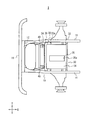
- FIG. 3 is a view of the vehicle 1 of FIG. 1 as viewed from below.
- FIG. 4 is a view for explaining an exhaust flow of the radiator fan 22.
- ⁇ Vehicle configuration> A configuration of the vehicle 1 according to an embodiment of the present disclosure will be described with reference to FIGS. 1 to 3.
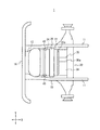
- FIG. 1 is a schematic diagram for explaining an example of a configuration of a vehicle 1 according to an embodiment.
- FIG. 2 is a view of the vehicle 1 of FIG. 1 as viewed from above.
- FIG. 3 is a view of the vehicle 1 of FIG. 1 as viewed from below. 1 to 3, only the front portion of the vehicle 1 is shown for convenience of explanation.
- Vehicle 1 is a large vehicle, here a truck. As shown in FIG. 1, the vehicle 1 includes a vehicle body frame 10, a front bumper 16, a front grill 18, a radiator 20, a radiator fan 22, an intercooler 24, and a suspension member 30.
- the body frame 10 is a skeleton that supports the vehicle 1. As shown in FIG. 2, the vehicle body frame 10 has a pair of side frames 11 extending in the front-rear direction of the vehicle 1 (X direction in FIG. 2) and a vehicle width direction (see FIG. 2 in the Y direction). An engine (not shown) is attached to the body frame 10.
- the front bumper 16 is provided in the front part of the vehicle body frame 10 along the vehicle width direction. Specifically, the front bumper 16 is attached to the cross member 12 located at the front end of the vehicle body frame 10.
- the front bumper 16 is a shock absorber, and has a function of reducing the impact at the time of collision with another vehicle or the like.
- the front grill 18 is provided above the front bumper 16.
- the front grille 18 is positioned in front of the radiator 20 and the intercooler 24 and has a function of preventing damage to the radiator 20 and the like. 2 and 3, the front grille 18 is omitted for convenience of explanation.
- the front grill 18 is formed with a plurality of openings for taking in air (for example, traveling wind when the vehicle 1 is traveling). Further, in the present embodiment, an opening 19 formed along the vehicle width direction is provided between the front grille 18 and the front bumper 16. The air that flows from the opening 19 flows toward the radiator 20 and the intercooler 24.
- the radiator 20 is a cooling device that cools engine coolant.
- a passage through which cooling water flows is formed in the radiator 20.
- the cooling water circulates between the radiator 20 and the engine, and the radiator 20 cools the cooling water warmed when passing through the engine.
- the radiator 20 cools the cooling water by exchanging heat between the traveling wind when the vehicle 1 is traveling and the cooling water that has passed through the engine.
- the radiator fan 22 is provided on the back side of the radiator 20. Specifically, the radiator fan 22 is provided between the radiator 20 and the engine. The radiator fan 22 is located on the center side of the vehicle 1 in the vehicle width direction.
- the radiator fan 22 is an electric fan that is connected to the engine and rotates by receiving power from the engine.
- the radiator fan 22 has a blade portion 22a including a plurality of blades that rotate by receiving the power of the engine.
- the radiator fan 22 sucks and exhausts air in front of the radiator 20 as the blade portion 22a rotates. Thereby, the cooling water flowing through the radiator 20 is cooled by the air.
- the radiator fan 22 also cools the engine disposed on the back side.
- the radiator fan 22 discharges the sucked air (exhaust gas) downward. Specifically, the exhaust gas flows toward the suspension member 30 provided below the radiator fan 22. Although details will be described later, an opening is provided in the suspension member 30 in order to efficiently exhaust the exhaust to the outside of the vehicle.
- the intercooler 24 is for cooling air (hereinafter referred to as pressurized air) pressurized in a supercharging device (not shown) of the vehicle 1.
- pressurized air pressurized air
- the intercooler 24 cools the pressurized air by exchanging heat between the traveling air during traveling of the vehicle 1 and the pressurized air.
- the intercooler 24 is provided in front of the radiator 20 and faces the lower portion of the radiator 20.
- the intercooler 24 is attached to the front surface of the radiator 20.
- the suspension member 30 is a sub-frame for fixing a suspension arm (rod), which is a suspension device for suspending wheels on the axle 5, to the vehicle body frame 10. For this reason, the suspension member 30 forms part of the vehicle body frame 10 of the vehicle 1.
- the suspension member 30 is connected to the pair of side frames 11.
- the suspension member 30 is located below the radiator fan 22. For this reason, the exhaust of the radiator fan 22 is directed to the suspension member 30.
- the suspension member 30 includes a pair of cross members 32 and a flat plate member 34.
- the pair of cross members 32 extend in the vehicle width direction of the vehicle 1 in the same manner as the cross member 12 of the vehicle body frame 10.
- the pair of cross members 32 are arranged at a predetermined interval in the front-rear direction of the vehicle 1. Further, the pair of cross members 32 are respectively supported by the side frames 11 of the vehicle body frame 10. For example, the pair of cross members 32 are respectively connected to the side frames 11 via the connecting members 40.
- the flat plate member 34 is disposed between the pair of cross members 32 and is fixed to each of the bottom surfaces of the pair of cross members 32.
- the flat plate member 34 has a rectangular shape.
- the flat plate member 34 forms a flat floor surface of the vehicle 1.
- the flat plate member is formed flat so that the entire surface thereof is substantially parallel to the longitudinal direction of the vehicle 1.
- the flat plate member 34 has a function of adjusting the flow of air below the body frame 10.
- the flat plate member 34 is provided with an opening 35.
- the opening 35 has a discharge port 35a for discharging the exhaust of the radiator fan 22 outward.
- FIG. 4 is a view for explaining an exhaust flow of the radiator fan 22. Since the exhaust of the radiator fan 22 is discharged outside the vehicle through the discharge port 35a (FIG. 3), it is possible to suppress the exhaust from being filled in the region between the radiator fan 22 and the flat plate member 34. Thereby, since the subsequent intake by the radiator fan 22 is also appropriately performed, it is possible to prevent the cooling water and the engine cooling efficiency from being reduced by the radiator fan 22.
- the discharge port 35a is formed in a portion of the flat plate member 34 where exhaust is concentrated. Specifically, as shown in FIG. 3, the discharge port 35 a is formed on the center side of the flat plate member 34 in the vehicle width direction so that the longitudinal direction is parallel to the front-rear direction of the vehicle 1. In such a case, the exhaust of the radiator fan 22 can be efficiently discharged to the outside of the vehicle, so that a reduction in cooling efficiency by the radiator fan 22 can be more effectively prevented.
- the shape of the discharge port 35a is rectangular, but is not limited thereto.
- the shape of the discharge port 35a may be circular.
- the vehicle 1 includes the flat plate member 34 attached to the frame (specifically, the suspension member 30) below the radiator fan 22.
- the flat plate member 34 is formed with a discharge port 35a for discharging the exhaust of the radiator fan 22 outward.
- the flow of air below the vehicle body frame 10 is adjusted by using the flat plate member 34 that is a flat floor surface, and the radiator fan 22 and the flat plate member 34 are formed by the discharge port 35 a formed in the flat plate member 34. It is possible to suppress the exhaust gas from filling the area between the two. Thereby, since the intake and exhaust of the radiator fan 22 are performed smoothly, a decrease in cooling efficiency by the radiator fan 22 can be suppressed.
- the flat plate member 34 serving as the floor surface of the vehicle 1 is attached to the suspension member 30.
- the present invention is not limited to this.
- the flat plate member 34 may be attached to another frame of the vehicle body frame 10.
- the vehicle 1 is a truck, but the present invention is not limited to this.
- the vehicle 1 may be a bus or the like.
- the present invention has an effect of suppressing a decrease in cooling efficiency due to a radiator fan, and is useful for a vehicle having a radiator fan.
Landscapes
- Engineering & Computer Science (AREA)
- Chemical & Material Sciences (AREA)
- Combustion & Propulsion (AREA)
- Transportation (AREA)
- Mechanical Engineering (AREA)
- Body Structure For Vehicles (AREA)
- Cooling, Air Intake And Gas Exhaust, And Fuel Tank Arrangements In Propulsion Units (AREA)
Abstract
L'invention concerne un véhicule (1) ayant un radiateur (20), un ventilateur de radiateur (22) qui est disposé à l'arrière du radiateur (20), aspire l'air devant le radiateur (20) et expulse l'air, et un élément de plaque plate (34) qui est monté sur un élément de suspension (30) en dessous du ventilateur de radiateur (22) et forme une surface de sol plate. L'élément de plaque plate (34) a un orifice d'échappement (35a) formé sur ce dernier servant à expulser l'air d'échappement du ventilateur de radiateur (22) vers l'extérieur.
Applications Claiming Priority (2)
| Application Number | Priority Date | Filing Date | Title |
|---|---|---|---|
| JP2016-111523 | 2016-06-03 | ||
| JP2016111523A JP6720701B2 (ja) | 2016-06-03 | 2016-06-03 | 車両 |
Publications (1)
| Publication Number | Publication Date |
|---|---|
| WO2017209012A1 true WO2017209012A1 (fr) | 2017-12-07 |
Family
ID=60477577
Family Applications (1)
| Application Number | Title | Priority Date | Filing Date |
|---|---|---|---|
| PCT/JP2017/019771 Ceased WO2017209012A1 (fr) | 2016-06-03 | 2017-05-26 | Véhicule |
Country Status (2)
| Country | Link |
|---|---|
| JP (1) | JP6720701B2 (fr) |
| WO (1) | WO2017209012A1 (fr) |
Families Citing this family (1)
| Publication number | Priority date | Publication date | Assignee | Title |
|---|---|---|---|---|
| JP7119818B2 (ja) | 2018-09-18 | 2022-08-17 | トヨタ自動車株式会社 | 車両前部構造 |
Citations (6)
| Publication number | Priority date | Publication date | Assignee | Title |
|---|---|---|---|---|
| JPS583377U (ja) * | 1981-06-30 | 1983-01-10 | 日産自動車株式会社 | 自動車のフロントエプロン構造 |
| JPS59135282U (ja) * | 1983-02-28 | 1984-09-10 | 日野自動車株式会社 | 自動車のアンダカバ− |
| JPS6023423U (ja) * | 1983-07-26 | 1985-02-18 | 富士重工業株式会社 | エンジン室のアンダガ−ド |
| JPH0672789U (ja) * | 1993-03-29 | 1994-10-11 | 日産車体株式会社 | 車両のアンダーカバー構造 |
| JPH09226387A (ja) * | 1996-02-29 | 1997-09-02 | Hino Motors Ltd | 遮蔽カバー |
| JP2007001419A (ja) * | 2005-06-23 | 2007-01-11 | Honda Motor Co Ltd | 車両前部構造 |
Family Cites Families (1)
| Publication number | Priority date | Publication date | Assignee | Title |
|---|---|---|---|---|
| JPH09193839A (ja) * | 1995-11-17 | 1997-07-29 | Nissan Motor Co Ltd | 自動車のアンダーフロア構造 |
-
2016
- 2016-06-03 JP JP2016111523A patent/JP6720701B2/ja active Active
-
2017
- 2017-05-26 WO PCT/JP2017/019771 patent/WO2017209012A1/fr not_active Ceased
Patent Citations (6)
| Publication number | Priority date | Publication date | Assignee | Title |
|---|---|---|---|---|
| JPS583377U (ja) * | 1981-06-30 | 1983-01-10 | 日産自動車株式会社 | 自動車のフロントエプロン構造 |
| JPS59135282U (ja) * | 1983-02-28 | 1984-09-10 | 日野自動車株式会社 | 自動車のアンダカバ− |
| JPS6023423U (ja) * | 1983-07-26 | 1985-02-18 | 富士重工業株式会社 | エンジン室のアンダガ−ド |
| JPH0672789U (ja) * | 1993-03-29 | 1994-10-11 | 日産車体株式会社 | 車両のアンダーカバー構造 |
| JPH09226387A (ja) * | 1996-02-29 | 1997-09-02 | Hino Motors Ltd | 遮蔽カバー |
| JP2007001419A (ja) * | 2005-06-23 | 2007-01-11 | Honda Motor Co Ltd | 車両前部構造 |
Also Published As
| Publication number | Publication date |
|---|---|
| JP6720701B2 (ja) | 2020-07-08 |
| JP2017217931A (ja) | 2017-12-14 |
Similar Documents
| Publication | Publication Date | Title |
|---|---|---|
| US8701811B2 (en) | Battery cooling system and method | |
| JP2012025188A (ja) | 車両の前部車体構造 | |
| JPWO2012029088A1 (ja) | 車両 | |
| WO2017209012A1 (fr) | Véhicule | |
| JP2016137824A (ja) | アンダーカバー | |
| JP6015513B2 (ja) | 冷却構造 | |
| JP2013100023A (ja) | 車両前部構造 | |
| JP2015085824A (ja) | 車両の前部構造 | |
| JP6405123B2 (ja) | 車両の整流装置 | |
| JP2007290465A (ja) | 車両の前端構造 | |
| JP2006044337A (ja) | 車両用冷却装置 | |
| JP2018058531A (ja) | 冷却システム | |
| JP5473816B2 (ja) | 作業車 | |
| JP6798209B2 (ja) | 車両用アンダーカバー構造 | |
| JP5732796B2 (ja) | サブラジエータの搭載構造 | |
| CN106005058B (zh) | 整流装置 | |
| JP2016055751A (ja) | 車両のアンダカバー構造 | |
| JP2011057172A (ja) | タイヤ昇温装置 | |
| JP5003950B2 (ja) | 車両のパワートレイン配設構造 | |
| JP2017217994A (ja) | 車両 | |
| EP2620610A1 (fr) | Support avant de véhicule à moteur comprenant une ouverture oblongue et module de refroidissement | |
| JP2019069645A (ja) | 車両 | |
| JP2017149191A (ja) | 車輌フレーム、及び車輌 | |
| JP2017226252A (ja) | 車両の冷却装置 | |
| JP2018118571A (ja) | 車両 |
Legal Events
| Date | Code | Title | Description |
|---|---|---|---|
| 121 | Ep: the epo has been informed by wipo that ep was designated in this application |
Ref document number: 17806567 Country of ref document: EP Kind code of ref document: A1 |
|
| NENP | Non-entry into the national phase |
Ref country code: DE |
|
| 122 | Ep: pct application non-entry in european phase |
Ref document number: 17806567 Country of ref document: EP Kind code of ref document: A1 |