WO2017217536A1 - Dispositif optique, unité optique, dispositif d'affichage et procédé de fixation de prisme - Google Patents
Dispositif optique, unité optique, dispositif d'affichage et procédé de fixation de prisme Download PDFInfo
- Publication number
- WO2017217536A1 WO2017217536A1 PCT/JP2017/022343 JP2017022343W WO2017217536A1 WO 2017217536 A1 WO2017217536 A1 WO 2017217536A1 JP 2017022343 W JP2017022343 W JP 2017022343W WO 2017217536 A1 WO2017217536 A1 WO 2017217536A1
- Authority
- WO
- WIPO (PCT)
- Prior art keywords
- prism
- positioning member
- seating surface
- adhesive
- optical device
- Prior art date
- Legal status (The legal status is an assumption and is not a legal conclusion. Google has not performed a legal analysis and makes no representation as to the accuracy of the status listed.)
- Ceased
Links
Images


Classifications
-
- G—PHYSICS
- G02—OPTICS
- G02B—OPTICAL ELEMENTS, SYSTEMS OR APPARATUS
- G02B7/00—Mountings, adjusting means, or light-tight connections, for optical elements
- G02B7/18—Mountings, adjusting means, or light-tight connections, for optical elements for prisms; for mirrors
- G02B7/1805—Mountings, adjusting means, or light-tight connections, for optical elements for prisms; for mirrors for prisms
-
- H—ELECTRICITY
- H01—ELECTRIC ELEMENTS
- H01S—DEVICES USING THE PROCESS OF LIGHT AMPLIFICATION BY STIMULATED EMISSION OF RADIATION [LASER] TO AMPLIFY OR GENERATE LIGHT; DEVICES USING STIMULATED EMISSION OF ELECTROMAGNETIC RADIATION IN WAVE RANGES OTHER THAN OPTICAL
- H01S5/00—Semiconductor lasers
- H01S5/40—Arrangement of two or more semiconductor lasers, not provided for in groups H01S5/02 - H01S5/30
- H01S5/4012—Beam combining, e.g. by the use of fibres, gratings, polarisers, prisms
-
- G—PHYSICS
- G02—OPTICS
- G02B—OPTICAL ELEMENTS, SYSTEMS OR APPARATUS
- G02B26/00—Optical devices or arrangements for the control of light using movable or deformable optical elements
- G02B26/08—Optical devices or arrangements for the control of light using movable or deformable optical elements for controlling the direction of light
- G02B26/0816—Optical devices or arrangements for the control of light using movable or deformable optical elements for controlling the direction of light by means of one or more reflecting elements
- G02B26/0833—Optical devices or arrangements for the control of light using movable or deformable optical elements for controlling the direction of light by means of one or more reflecting elements the reflecting element being a micromechanical device, e.g. a MEMS mirror, DMD
-
- G—PHYSICS
- G02—OPTICS
- G02B—OPTICAL ELEMENTS, SYSTEMS OR APPARATUS
- G02B26/00—Optical devices or arrangements for the control of light using movable or deformable optical elements
- G02B26/08—Optical devices or arrangements for the control of light using movable or deformable optical elements for controlling the direction of light
- G02B26/10—Scanning systems
-
- H—ELECTRICITY
- H01—ELECTRIC ELEMENTS
- H01S—DEVICES USING THE PROCESS OF LIGHT AMPLIFICATION BY STIMULATED EMISSION OF RADIATION [LASER] TO AMPLIFY OR GENERATE LIGHT; DEVICES USING STIMULATED EMISSION OF ELECTROMAGNETIC RADIATION IN WAVE RANGES OTHER THAN OPTICAL
- H01S5/00—Semiconductor lasers
- H01S5/02—Structural details or components not essential to laser action
- H01S5/022—Mountings; Housings
- H01S5/0225—Out-coupling of light
- H01S5/02253—Out-coupling of light using lenses
-
- H—ELECTRICITY
- H01—ELECTRIC ELEMENTS
- H01S—DEVICES USING THE PROCESS OF LIGHT AMPLIFICATION BY STIMULATED EMISSION OF RADIATION [LASER] TO AMPLIFY OR GENERATE LIGHT; DEVICES USING STIMULATED EMISSION OF ELECTROMAGNETIC RADIATION IN WAVE RANGES OTHER THAN OPTICAL
- H01S5/00—Semiconductor lasers
- H01S5/02—Structural details or components not essential to laser action
- H01S5/022—Mountings; Housings
- H01S5/023—Mount members, e.g. sub-mount members
- H01S5/02325—Mechanically integrated components on mount members or optical micro-benches
-
- H—ELECTRICITY
- H01—ELECTRIC ELEMENTS
- H01S—DEVICES USING THE PROCESS OF LIGHT AMPLIFICATION BY STIMULATED EMISSION OF RADIATION [LASER] TO AMPLIFY OR GENERATE LIGHT; DEVICES USING STIMULATED EMISSION OF ELECTROMAGNETIC RADIATION IN WAVE RANGES OTHER THAN OPTICAL
- H01S5/00—Semiconductor lasers
- H01S5/02—Structural details or components not essential to laser action
- H01S5/022—Mountings; Housings
- H01S5/0235—Method for mounting laser chips
-
- H—ELECTRICITY
- H01—ELECTRIC ELEMENTS
- H01S—DEVICES USING THE PROCESS OF LIGHT AMPLIFICATION BY STIMULATED EMISSION OF RADIATION [LASER] TO AMPLIFY OR GENERATE LIGHT; DEVICES USING STIMULATED EMISSION OF ELECTROMAGNETIC RADIATION IN WAVE RANGES OTHER THAN OPTICAL
- H01S5/00—Semiconductor lasers
- H01S5/40—Arrangement of two or more semiconductor lasers, not provided for in groups H01S5/02 - H01S5/30
- H01S5/4025—Array arrangements, e.g. constituted by discrete laser diodes or laser bar
- H01S5/4087—Array arrangements, e.g. constituted by discrete laser diodes or laser bar emitting more than one wavelength
- H01S5/4093—Red, green and blue [RGB] generated directly by laser action or by a combination of laser action with nonlinear frequency conversion
-
- G—PHYSICS
- G02—OPTICS
- G02B—OPTICAL ELEMENTS, SYSTEMS OR APPARATUS
- G02B27/00—Optical systems or apparatus not provided for by any of the groups G02B1/00 - G02B26/00, G02B30/00
- G02B27/01—Head-up displays
- G02B27/0101—Head-up displays characterised by optical features
Definitions
- the present invention relates to an optical device, an optical unit, a display device, and a prism fixing method.
- Prisms such as dichroic prisms and beam splitter prisms are used in a projector or the like as optical components for color separation and color synthesis.
- a plurality of these components are generally used and are in many cases fixed with an adhesive such as ultraviolet curable resin.
- an adhesive such as ultraviolet curable resin.
- a relative positional relationship of a light incident surface such as displacement of pixels of each color light and deviation of an optical axis, directly affects image quality. Therefore, a high-precision and stable fixing method is required for the optical components.
- Patent Literature 1 discloses a prism unit in which a prism base includes at least three seating surfaces attached to a surface orthogonal to the reflective surfaces of the prism and an adhesive seating-surface portion adhered to the prism by an adhesive and having a height lower than at least the three seating surfaces, in which the shape of at least the three seating surfaces is circular or polygonal, in which a groove portion having a shape along the shape of at least the three seating surfaces is formed between at least the three seating surfaces and the adhesive seating-surface portion, and in which the seating surfaces and the groove portion are adjacent to each other and the groove portion and the adhesive seating-surface portion are adjacent to each other.
- the prism such as the dichroic prism
- the bottom surface of the prism and a base plate or the like are directly adhered, when the thickness of an adhesive layer interposed therebetween is not exactly uniform, the prism is likely to be tilted without standing upright on the base plate.
- a method in which the heights of seating surfaces are made constant by providing a plurality of seating surfaces, an adhesive reservoir lower than the seating surfaces, and an adhesive removal groove around the seating surfaces and by separating the prism seating surface from an adhesive applied surface so as not to attach the adhesive to the seating surfaces.
- a target prism is a large prism with one side of the contact surface exceeding 10 mm. This is because, for a prism of 10 mm or less, it is difficult to machine a die for manufacturing a seating surface (receiving surface) and it becomes more difficult to machine it when three seating surfaces are provided. It is also difficult to set the prism to the seating surface and apply an adhesive thereto, which may result in erroneous application to the seating surface (prism contact surface).
- an optical device comprising: a rectangular parallelepiped prism configured to include a reflection-transmission surface for reflecting and transmitting light fluxes; a seating surface provided so that a bottom surface of the prism is fixed by an adhesive; and a groove portion provided in at least a part of the periphery of the seating surface, wherein the groove portion is formed so as to be capable of receiving the adhesive protruded from between the bottom surface of the prism and the seating surface when the prism is pressed against a first member for determining a position of the prism so that a first side face of the prism is along a predetermined straight line and against a second member for restricting a second side face orthogonal to the first side face of the prism from moving in the direction of the straight line, at the time of fixing the prism to the seating surface by the adhesive.
- Fig. 1 is a diagram illustrating an overview of a display device according to an embodiment.
- Fig. 2 is a perspective view illustrating a configuration example of a prism unit.
- Fig. 3 is a diagram illustrating a state before a prism in the prism unit is fixed.
- Fig. 4 is a diagram illustrating pressing directions when the prism in the prism unit is fixed.
- Fig. 5 is a perspective view illustrating a state in which the prism is fixed.
- Fig. 6A is a diagram illustrating an example of a relationship between incident directions of laser light fluxes and positions where first positioning members and a second positioning member are provided.
- Fig. 1 is a diagram illustrating an overview of a display device according to an embodiment.
- Fig. 2 is a perspective view illustrating a configuration example of a prism unit.
- Fig. 3 is a diagram illustrating a state before a prism in the prism unit is fixed.
- Fig. 4 is a diagram
- FIG. 6B is a diagram illustrating a comparative example of the relationship between incident directions of laser light fluxes and positions where the first positioning members and the second positioning member are provided.
- Fig. 7 is a perspective view illustrating a first modification of a positioning member that includes the first positioning members and the second positioning member.
- Fig. 8 is a perspective view illustrating a second modification of the positioning member.
- Fig. 9 is a perspective view illustrating a third modification of the positioning member.
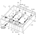
- Fig. 1 is a diagram illustrating an overview of a display device 1 according to an embodiment.
- the display device 1 is, for example, HuD (Head-up Display), and is mounted on a movable body such as a vehicle, an aircraft, and a ship.
- HuD Head-up Display
- the display device 1 includes, for example, a light source portion (optical unit) 10, a two-dimensional deflecting portion 11, a concave mirror 12, a scanned surface element 13, a concave mirror 14, and a reflective surface element 15, so that an observer can observe an enlarged virtual image 17.
- a light source portion optical unit
- a two-dimensional deflecting portion 11, a concave mirror 12, a scanned surface element 13, a concave mirror 14, and a reflective surface element 15, so that an observer can observe an enlarged virtual image 17.
- the light source portion 10 is a laser light source that includes a prism unit (optical device) 2 (which is explained later with reference to Fig. 2) and emits a pixel display beam LC (laser light) for color image display.
- the pixel display beam LC is a beam obtained by combining beams of three colors of red (hereinafter, referred to as "R"), green (hereinafter, referred to as “G”), and blue (hereinafter, referred to as "B”) into one beam, and the prism unit 2 combines R, G, B laser light fluxes into a single light flux, and irradiates the two-dimensional deflecting portion 11 with the light flux.
- the two-dimensional deflecting portion 11 deflects the pixel display beam LC emitted from the light source portion 10 in a two-dimensional direction.
- the two-dimensional deflecting portion 11 is configured to swing a micro-mirror on "two axes orthogonal to each other" as swing axes. That is, the two-dimensional deflecting portion 11 is MEMS (Micro Electro Mechanical Systems) or the like manufactured as a micro swinging mirror element in a semiconductor process or the like.
- the two-dimensional deflecting portion 11 may be a combination, etc. of, for example, two micro-mirrors each swinging around one axis so that swinging directions are orthogonal to each other.
- the pixel display beam LC deflected in the two-dimensional direction is irradiated to the concave mirror 12.
- the concave mirror 12 reflects the incident pixel display beam LC toward the scanned surface element 13.
- the optical action of the concave mirror 12 is to reflect incident pixel display beams LC deflected in the two-dimensional direction and to align the directions of the reflected pixel display beams LC in a certain direction.
- the pixel display beam LC reflected by the concave mirror 12 is incident on the scanned surface element 13 while moving in parallel in association with the deflection by the two-dimensional deflecting portion 11, and scans the scanned surface element 13 in the two-dimensional direction.
- the scanned surface element 13 is, for example, a microlens array of a "fine convex lens structure".
- "two-dimensional color image” is formed on the scanned surface element 13. It is needless to say that a pixel to be displayed at each moment is "only a pixel irradiated by the pixel display beam LC at that moment".
- a two-dimensional color image is formed as "a set of pixels displayed at respective moments" through scanning in the two-dimensional direction by the pixel display beam LC.
- the concave mirror 14 reflects the light constituting the "two-dimensional color image" formed on the scanned surface element 13.
- the scanned surface element 13 and the concave mirror 14 constitute a virtual image forming optical system.
- "Virtual image forming optical system” forms the enlarged virtual image 17 of the two-dimensional color image.
- the reflective surface element 15 is provided on the front side of the imaging position of the enlarged virtual image 17, and reflects the light flux forming the enlarged virtual image 17 toward an observer side (represented by an observer's eye in the drawing). With this reflected light, the observer can visually recognize the enlarged virtual image 17.
- Fig. 2 is a perspective view illustrating a configuration example of the prism unit 2.
- Light sources 20a, 20b, and 20c are laser diodes or the like which are fixed to an LD substrate 21, and emit laser beams of R, G, and B, respectively.
- Coupling lenses 22a, 22b, and 22c suppress divergence of the laser beams of the colors respectively emitted from the light sources 20a, 20b, and 20c.
- a laser light flux LB of B is deflected by a mirror 23 to enter a prism 24b.
- a laser light flux LG of G also enters the prism 24b.
- the prism 24b has a dichroic film 25b that transmits the laser light flux LB and reflects the laser light flux LG.
- the prism 24b is a rectangular parallelepiped prism in which one reflection-transmission surface (dichroic film 25b) that reflects a light flux of a predetermined wavelength and transmits a light flux of other wavelength is internally provided so as to be surrounded by at least four apexes and the bottom surface, and deflects the laser light flux LG and transmits the laser light flux LB to enter a prism 24a.
- the prism 24a has a dichroic film 25a that transmits the laser light fluxes LG and LB and reflects the laser light flux LR.
- the prism 24a is a rectangular parallelepiped prism in which one reflection-transmission surface (dichroic film 25a) that reflects a light flux of a predetermined wavelength and transmits a light flux of other wavelength is internally provided so as to be surrounded by at least four apexes and the bottom surface. Therefore, the laser light fluxes of the colors of LR, LG, and LB are combined into one light flux and emitted from the prism 24a.
- the light flux emitted from the prism 24a is converted into a "collimated beam" of a predetermined light flux diameter by a lens. This "collimated beam” is the pixel display beam LC.
- the laser light fluxes of the R, G, and B colors that constitute the pixel display beam LC are intensity-modified by an image signal of "two-dimensional color image" to be displayed.
- the amount of emitted light is set based on the amount of light detected by a light-receiving sensor.
- the light-receiving sensor detects the light amounts of the laser light flux LR transmitted without being reflected by the prism 24a and of the laser light fluxes LG and LB not transmitted by the prism 24a.
- the prism 24a and the prism 24b are fixed to respective seating surfaces 26 with an adhesive in a housing 201.
- the seating surfaces 26 are formed fixedly on a substrate 210 of the housing 201.
- the seating surfaces 26 may be formed separately from the substrate 210 of the housing 210.
- the seating surfaces 26 may be formed integrally with the substrate 210, in other words, a part of the substrate 210 may be configured to be functioned as the seating surface.
- the prism 24a and the prism 24b are positioned respectively by positioning member that includes first positioning members 27 and a second positioning member 28 at the time of being fixed.
- a groove portion 29 is formed in a part of the periphery of the seating surface 26.
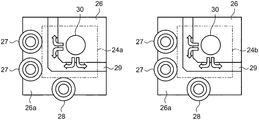
- Fig. 3 is a diagram illustrating a state before the prism 24a and the prism 24b are fixed in the prism unit 2.
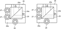
- Fig. 4 is a diagram illustrating pressing directions when the prism 24a and the prism 24b are fixed in the prism unit 2.
- Fig. 5 is a perspective view illustrating a state in which the prism 24a is fixed.
- the seating surface 26 is provided so that the bottom surface (adhesive surface) of the prism 24a or the prism 24b is fixed by an adhesive.
- the respective seating surfaces 26 are preferably set so as to be equal to or slightly larger than the respective adhesive surfaces of the prism 24a and the prism 24b.
- the prism 24a and the prism 24b are, for example, a rectangular parallelepiped (or cube) having a side length of 10 mm or less. Therefore, each one side of the seating surfaces 26 is also set to, for example, about 10 mm or less. Because the seating surface 26 has a small area, each surface is further reduced when divided, which makes it difficult to perform processing and apply the adhesive thereto. On the other hand, because the seating surface 26 has a small area, variations in flatness of each area hardly occur. That is, the seating surface 26 does not need to be divided.
- the adhesive surfaces of the prism 24a and the prism 24b have sufficient planarity. Therefore, by applying a uniform load to the surfaces opposite to the adhesive surfaces of the prism 24a and the prism 24b, the film thickness of the adhesive layer is made uniform, and thickness unevenness is eliminated. In other words, the prism 24a and the prism 24b are adhered thereto without tilting. Because each area of the seating surfaces 26 is narrow, the amount of adhesive is small, but the weight of the prism 24a and the prism 24b is light, so that it is possible to obtain sufficient adhesion.
- the first positioning members 27 and the second positioning member 28 are provided near the respective seating surfaces 26.
- the first positioning members 27 are, for example, two reference pins and positions the prism 24a or the prism 24b so that its first side face is along a predetermined straight line.
- the second positioning member 28 is, for example, one reference pin and restricts a second side face orthogonal to the first side face of the prism 24a or the prism 24b from moving in the direction in which the straight line extends.
- the groove portion 29 is provided between an adhesive applied position 30 and the first positioning members 27/the second positioning member 28.
- the groove portion 29 is formed so that the length in the direction intersecting a direction from the seating surface 26 to the first positioning members 27 or to the second positioning member 28 is longer than the length in the direction from the seating surface 26 to the first positioning members 27 or to the second positioning member 28.
- a member surface 26a filling a space between the first positioning members 27/the second positioning member 28 and the groove portion 29 is set to be equal to or slightly lower than the height of the respective seating surfaces 26 and is set to be higher than the groove portion 29.
- the prism 24a and the prism 24b are positioned by being pressed in the directions of the arrows illustrated in Fig. 4 when being adhered to the respective seating surfaces 26 by the adhesive. In addition, by pressing the prism 24a and the prism 24b against the respective seating surfaces 26, extra adhesive is pushed out, and the film thickness of the adhesive is made uniform.
- the prism 24a and the prism 24b are pressed in the directions of the arrows to come into contact with the first positioning members 27 and the second positioning member 28.
- Each of the prism 24a and the prism 24b may be pressed against the second positioning member 28 after being pressed against the first positioning members 27.
- the extra adhesive crushed by the prism 24a and the prism 24b flows in the directions of the arrows illustrated in Fig. 3, and does not reach the first positioning members 27 and the second positioning member 28 even if it flows in the groove portion 29. Even if the extra adhesive flows between the first positioning members 27/the second positioning member 28 and the groove portion 29, it is a small amount, and the adhesive does not reach the first positioning members 27 and the second positioning member 28. Moreover, when the portion between the first positioning members 27/the second positioning member 28 and the groove portion 29 is set to be lower than the seating surface 26, the adhesive does not affect the attitudes of the prism 24a and the prism 24b after being fixed. Thereafter, the prism 24a and the prism 24b are reliably adhered to the respective seating surfaces 26 by being irradiated with ultraviolet rays and stored at a high temperature, or the like.
- the first positioning members 27 and the second positioning member 28 are provided so as not to block or damage optically effective areas 200a and 200b of the prism 24a (or prism 24b) through which a light flux passes. It is only necessary for the first positioning members 27 and the second positioning member 28 to be arranged so as not to block the passage of the light flux, and they may be arranged in the lower part of the optically effective areas 200a and 200b or may be arranged on the sides of the optically effective areas 200a and 200b.
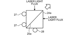
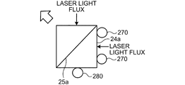
- Figs. 6A and 6B are diagrams illustrating a relationship between an incident direction of a laser light flux and positions where the first positioning members 27 and the second positioning member 28 are provided.
- Fig. 6A represents an example
- Fig. 6B represents a comparative example.
- a direction, in which the prism 24a is likely to be displaced when it is positioned is a direction of the arrow of Fig. 6A.
- the prism 24a is displaced in the direction in which the dichroic film 25a extends at the time of positioning, only the position where the light flux in the dichroic film 25a is transmitted or reflected is changed, and the direction in which the light flux is transmitted or reflected is not largely displaced.
- the direction, in which the prism 24a is likely to be displaced when it is positioned is a direction of the arrow of Fig. 6B.
- the direction in which the prism 24a transmits or reflects the light flux may change.
- a combination of light fluxes may not be performed correctly.
- the prism 24a and the prism 24b are abutted against the first positioning members 27 and the second positioning member 28 and positioned when they are adhered to the respective seating surfaces 26 by an adhesive, and the groove portion 29 receives the extra adhesive, so that the prism 24a and the prism 24b are easily fixed with high accuracy.
- Fig. 7 is a perspective view illustrating a first modification of the positioning member including the first positioning members and the second positioning member.
- the first positioning members 27 including the two reference pins according to the embodiment may be configured by a first member 27a which is a single member (for example, widened).
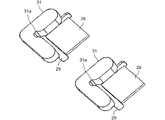
- Fig. 8 is a perspective view illustrating a second modification of the positioning member including the first positioning members and the second positioning member.
- the positioning member may be configured as a single member 31 that includes the first positioning members 27 and the second positioning member 28 according to the embodiment in an integrated fashion.
- the positioning member 31 includes two contact surfaces that are intersected each other and are contact with the prism 24a (or prism 24b), and is provided with a relief groove 31a at the intersection of the contact surfaces.
- the prism 24a (or prism 24b) can be reliably abutted against the contact surfaces of the positioning member 31 without contacting a corner of the prism 24a (or prism 24b) with the intersection of the contact surfaces of the positioning member 31. Because the two contact surfaces of the positioning member 31 in contact with the prism 24a (or prism 24b) can be processed at one time, high position accuracy can be achieved. Moreover, because the positioning member 31 can receive protrusion of the adhesive by the groove portion 29 and relief groove 31a, the adhesive can be prevented from being adhered to surfaces other the adhesive surface of the prism 24a (or prism 24b).
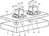
- Fig. 9 is a perspective view illustrating a third modification of the positioning member including the first positioning members and the second positioning member.
- the first positioning members 27 and the second positioning member 28 according to the embodiment may be replaced with a plurality of first positioning members 40 and second positioning members 42 which are provided on a jig 4.
- the jig 4 is provided so that, for example, four first positioning members 40 and two second positioning members 42 extend upward.
- the substrate 210 includes thereon seating surfaces (not shown), and a groove portion (not shown) is provided in at least a part of the periphery of each of the seating surfaces.
- the openings 202 are formed at positions opposite to the respective seating surfaces across the respective groove portions.
- the seating surfaces may be formed separately from the substrate 210 or integrally with the substrate 210, thus, in the modification, also the seating surfaces (not shown) may be formed separately from the substrate 210 or integrally with the substrate 210.
- the openings 202 are provided at positions corresponding to the first positioning members 27 and the second positioning member 28, and each diameter thereof is made larger than that of the first positioning members 40 and the second positioning members 42. In other words, the jig 4 is moved upward and downward at a predetermined position, which causes the first positioning members 40 and the second positioning members 42 to pass through or retract from the openings 202.
- the operator applies the adhesive to the prism adhesive surfaces of the substrate 210, and sets up the prism 24a and the prism 24b thereon. At this time, the operator abuts the prism 24a and the prism 24b against the first positioning members 40 and the second positioning members 42 respectively to position, and ejects extra adhesive into the grooves provided at the periphery of the respective seating surfaces on the substrate 210. Thereafter, the operator cures the adhesive by UV irradiation or high temperature storage, lowers the jig 4 downward, and retracts the first positioning members 40 and the second positioning members 42 from the openings 202 to remove the first positioning members 40 and the second positioning members 42 together with the jig 4 from the housing 201.
- Display device 2 Prism unit (Optical device) 4 Jig 20a, 20b, 20c Light source 22a, 22b, 22c Coupling lens 23 Mirror 24a, 24b Prism 25a, 25b Dichroic film 26 Seating surface 26a Member surface 27, 27a First positioning member 28 Second positioning member 29 Groove portion 30 Adhesive applied position 31 Positioning member 40 First positioning member 42 Second positioning member 200a, 200b Optically effective area 202 Opening
Landscapes
- Physics & Mathematics (AREA)
- General Physics & Mathematics (AREA)
- Optics & Photonics (AREA)
- Condensed Matter Physics & Semiconductors (AREA)
- Electromagnetism (AREA)
- Mounting And Adjusting Of Optical Elements (AREA)
- Optical Elements Other Than Lenses (AREA)
- Mechanical Optical Scanning Systems (AREA)
Abstract
Un dispositif optique comprend un prisme en forme de parallélépipède rectangle comportant : une surface de réflexion et de transmission conçue pour réfléchir et transmettre des flux lumineux ; une surface d'appui disposée de telle sorte qu'une surface inférieure du prisme est fixée par un adhésif ; et une partie de rainure située dans une partie de la périphérie de la surface d'appui. Une fois le prisme fixé à la surface d'appui par l'adhésif, la partie de rainure est conçue pour pouvoir recevoir l'adhésif faisant saillie entre la surface inférieure du prisme et la surface d'appui lorsque le prisme est appuyé contre un premier élément de positionnement afin de déterminer une position du prisme telle qu'une première surface latérale du prisme se trouve le long d'une ligne droite prédéterminée et contre un second élément de positionnement afin de limiter le déplacement dans la direction de la ligne droite d'une seconde surface latérale perpendiculaire à la première surface latérale du prisme.
Priority Applications (2)
| Application Number | Priority Date | Filing Date | Title |
|---|---|---|---|
| US16/309,293 US10923883B2 (en) | 2016-06-17 | 2017-06-16 | Optical device, optical unit, display device, and prism fixing method |
| EP17734847.1A EP3472653B1 (fr) | 2016-06-17 | 2017-06-16 | Dispositif optique, unité optique, dispositif d'affichage et procédé de fixation de prisme |
Applications Claiming Priority (2)
| Application Number | Priority Date | Filing Date | Title |
|---|---|---|---|
| JP2016120630A JP2017223893A (ja) | 2016-06-17 | 2016-06-17 | 光学装置、光学ユニット、表示装置、及びプリズム固定方法 |
| JP2016-120630 | 2016-06-17 |
Publications (1)
| Publication Number | Publication Date |
|---|---|
| WO2017217536A1 true WO2017217536A1 (fr) | 2017-12-21 |
Family
ID=59270076
Family Applications (1)
| Application Number | Title | Priority Date | Filing Date |
|---|---|---|---|
| PCT/JP2017/022343 Ceased WO2017217536A1 (fr) | 2016-06-17 | 2017-06-16 | Dispositif optique, unité optique, dispositif d'affichage et procédé de fixation de prisme |
Country Status (4)
| Country | Link |
|---|---|
| US (1) | US10923883B2 (fr) |
| EP (1) | EP3472653B1 (fr) |
| JP (1) | JP2017223893A (fr) |
| WO (1) | WO2017217536A1 (fr) |
Families Citing this family (4)
| Publication number | Priority date | Publication date | Assignee | Title |
|---|---|---|---|---|
| CN109375337B (zh) * | 2018-11-16 | 2021-10-08 | 上海禾赛科技有限公司 | 一种棱镜固定结构 |
| JP7241859B2 (ja) * | 2019-03-29 | 2023-03-17 | 京セラ株式会社 | スライスミラー、面分光器、望遠鏡およびスライスミラーの製造方法 |
| CN110286458A (zh) * | 2019-07-24 | 2019-09-27 | 嘉兴旭锐电子科技有限公司 | 一种利用方块结构实现可重构的光学定位系统和方法 |
| CN113281875B (zh) * | 2021-02-07 | 2023-02-21 | 深圳市安华光电技术有限公司 | 光机及投影仪 |
Citations (8)
| Publication number | Priority date | Publication date | Assignee | Title |
|---|---|---|---|---|
| US4261646A (en) * | 1978-06-12 | 1981-04-14 | Universal Pioneer Corporation | Beam splitter for optical player |
| EP0703088A2 (fr) * | 1994-08-29 | 1996-03-27 | Konica Corporation | Dispositif de génération d'images avec unité de balayage optique à deux rayons |
| JP2000321480A (ja) * | 1999-05-06 | 2000-11-24 | Chinontec Kk | プリズム装置及びプリズム装置の製造方法 |
| JP2006251517A (ja) * | 2005-03-11 | 2006-09-21 | Ricoh Printing Systems Ltd | 光走査装置 |
| JP2010032796A (ja) * | 2008-07-29 | 2010-02-12 | Olympus Imaging Corp | 光走査型プロジェクタ |
| WO2011142210A1 (fr) * | 2010-05-12 | 2011-11-17 | コニカミノルタオプト株式会社 | Système optique à balayage et projecteur muni de ce dernier |
| CN102087399B (zh) * | 2010-12-30 | 2012-09-19 | 中国科学院长春光学精密机械与物理研究所 | 一种棱镜的固定方法 |
| JP5398894B2 (ja) | 2012-10-22 | 2014-01-29 | キヤノン株式会社 | プリズムユニット |
Family Cites Families (32)
| Publication number | Priority date | Publication date | Assignee | Title |
|---|---|---|---|---|
| JPS61282808A (ja) * | 1985-06-10 | 1986-12-13 | Matsushita Electric Ind Co Ltd | 部品取付装置 |
| JPS63304222A (ja) * | 1987-06-04 | 1988-12-12 | Minolta Camera Co Ltd | レ−ザ光源装置 |
| JPH05323167A (ja) * | 1992-05-20 | 1993-12-07 | Ricoh Co Ltd | 光学部品取り付け方法 |
| JPH10149559A (ja) * | 1996-11-19 | 1998-06-02 | Sankyo Seiki Mfg Co Ltd | レーザビーム出射装置 |
| JP3075236B2 (ja) * | 1997-10-29 | 2000-08-14 | 日本電気株式会社 | 光学ヘッド装置および光軸傾き調整治具 |
| JP2003177289A (ja) * | 2001-12-12 | 2003-06-27 | Minebea Co Ltd | 光軸調整機構、光軸調整機構付き偏光ビームスプリッタ、及び光軸調整機構の調整方法 |
| JP4480075B2 (ja) | 2004-09-16 | 2010-06-16 | 株式会社リコー | 光書き込み装置及び画像形成装置 |
| US7916161B2 (en) | 2006-02-13 | 2011-03-29 | Ricoh Company, Ltd. | Image forming apparatus |
| JP2008033141A (ja) | 2006-07-31 | 2008-02-14 | Ricoh Co Ltd | 光走査装置および光走査装置を用いた画像形成装置 |
| JP2008224965A (ja) | 2007-03-12 | 2008-09-25 | Ricoh Co Ltd | 光走査装置、および画像形成装置 |
| JP2009023102A (ja) | 2007-07-17 | 2009-02-05 | Ricoh Co Ltd | 光書込装置および画像形成装置 |
| JP4918439B2 (ja) | 2007-09-04 | 2012-04-18 | 株式会社リコー | 光書込装置及び画像形成装置 |
| JP5033548B2 (ja) | 2007-09-10 | 2012-09-26 | 株式会社リコー | 光書込装置及び画像形成装置 |
| JP5223452B2 (ja) * | 2008-05-20 | 2013-06-26 | 株式会社リコー | プロジェクタ及び投影画像形成方法及び車両用ヘッドアップディスプレイ装置 |
| JP5304380B2 (ja) | 2008-07-23 | 2013-10-02 | 株式会社リコー | 光走査装置、これを用いた画像投影装置、ヘッドアップディスプレイ装置および携帯電話機 |
| JP5729545B2 (ja) | 2010-05-20 | 2015-06-03 | 株式会社リコー | 光走査装置及び画像形成装置 |
| JP5565117B2 (ja) | 2010-06-07 | 2014-08-06 | 株式会社リコー | 撮像装置 |
| JP5397328B2 (ja) | 2010-06-28 | 2014-01-22 | 株式会社リコー | 画像形成装置 |
| JP5863029B2 (ja) | 2011-05-25 | 2016-02-16 | 株式会社リコー | 画像形成装置 |
| JP2013104746A (ja) | 2011-11-11 | 2013-05-30 | Ricoh Co Ltd | レーザレーダ装置 |
| JP5906697B2 (ja) | 2011-11-30 | 2016-04-20 | 株式会社リコー | 光照射装置、画像読取装置および画像形成装置 |
| JP5862251B2 (ja) | 2011-12-01 | 2016-02-16 | 株式会社リコー | 光照射装置、画像読取装置および画像形成装置 |
| JP5896215B2 (ja) | 2012-01-24 | 2016-03-30 | 株式会社リコー | 光走査装置及び画像形成装置 |
| JP5899964B2 (ja) | 2012-01-26 | 2016-04-06 | 株式会社リコー | 光書込装置及び画像形成装置 |
| JP2013201746A (ja) | 2012-02-24 | 2013-10-03 | Ricoh Co Ltd | 光照射光学系、画像読取装置及び画像形成装置 |
| JP2013216785A (ja) * | 2012-04-09 | 2013-10-24 | Sumitomo Electric Ind Ltd | 光学部品実装構造、波長選択デバイス、及び光学部品実装構造の製造方法 |
| JP2013254663A (ja) | 2012-06-07 | 2013-12-19 | Ricoh Co Ltd | 半導体発光素子を用いたled直管形ランプ及びそれを備えた照明装置 |
| JP6075685B2 (ja) | 2013-02-19 | 2017-02-08 | 株式会社リコー | 光走査装置および画像形成装置 |
| JP2015065634A (ja) | 2013-08-28 | 2015-04-09 | 株式会社リコー | 光照射装置、及び画像形成装置 |
| JP6369038B2 (ja) | 2014-02-05 | 2018-08-08 | 株式会社リコー | ヘッドアップディスプレイ装置 |
| JP6489410B2 (ja) | 2014-03-17 | 2019-03-27 | 株式会社リコー | 光走査装置および画像形成装置 |
| JP2016045231A (ja) * | 2014-08-20 | 2016-04-04 | パイオニア株式会社 | 画像表示装置 |
-
2016
- 2016-06-17 JP JP2016120630A patent/JP2017223893A/ja active Pending
-
2017
- 2017-06-16 US US16/309,293 patent/US10923883B2/en active Active
- 2017-06-16 WO PCT/JP2017/022343 patent/WO2017217536A1/fr not_active Ceased
- 2017-06-16 EP EP17734847.1A patent/EP3472653B1/fr active Active
Patent Citations (8)
| Publication number | Priority date | Publication date | Assignee | Title |
|---|---|---|---|---|
| US4261646A (en) * | 1978-06-12 | 1981-04-14 | Universal Pioneer Corporation | Beam splitter for optical player |
| EP0703088A2 (fr) * | 1994-08-29 | 1996-03-27 | Konica Corporation | Dispositif de génération d'images avec unité de balayage optique à deux rayons |
| JP2000321480A (ja) * | 1999-05-06 | 2000-11-24 | Chinontec Kk | プリズム装置及びプリズム装置の製造方法 |
| JP2006251517A (ja) * | 2005-03-11 | 2006-09-21 | Ricoh Printing Systems Ltd | 光走査装置 |
| JP2010032796A (ja) * | 2008-07-29 | 2010-02-12 | Olympus Imaging Corp | 光走査型プロジェクタ |
| WO2011142210A1 (fr) * | 2010-05-12 | 2011-11-17 | コニカミノルタオプト株式会社 | Système optique à balayage et projecteur muni de ce dernier |
| CN102087399B (zh) * | 2010-12-30 | 2012-09-19 | 中国科学院长春光学精密机械与物理研究所 | 一种棱镜的固定方法 |
| JP5398894B2 (ja) | 2012-10-22 | 2014-01-29 | キヤノン株式会社 | プリズムユニット |
Also Published As
| Publication number | Publication date |
|---|---|
| US20190260183A1 (en) | 2019-08-22 |
| EP3472653A1 (fr) | 2019-04-24 |
| US10923883B2 (en) | 2021-02-16 |
| JP2017223893A (ja) | 2017-12-21 |
| EP3472653B1 (fr) | 2023-02-22 |
Similar Documents
| Publication | Publication Date | Title |
|---|---|---|
| US8267532B2 (en) | Passive alignment method and its application in micro projection devices | |
| US10923883B2 (en) | Optical device, optical unit, display device, and prism fixing method | |
| CN105408805B (zh) | 光源装置以及投影装置 | |
| US10571685B2 (en) | Optical scanning control device | |
| US20080273568A1 (en) | Beam combiner for a multicolor laser display | |
| US10942352B2 (en) | Head-up display apparatus | |
| US10182217B2 (en) | Projection device and a method of manufacturing a projection device | |
| US20210339460A1 (en) | Optical shaping apparatus | |
| US20140098350A1 (en) | Optical device | |
| JPWO2018003589A1 (ja) | ヘッドアップディスプレイ装置 | |
| KR20200016210A (ko) | 주사형 표시 장치 및 주사형 표시 시스템 | |
| JP6524722B2 (ja) | 光走査装置、光走査装置における基板の固定方法、画像表示装置、車両 | |
| US20200182434A1 (en) | Light source module | |
| US12123589B1 (en) | Flood projector with microlens array | |
| CN112462564A (zh) | 激光光学投影模块及包含其的穿戴装置 | |
| JP2011170271A (ja) | 光学装置、光学部品の位置調整固定方法、及びレーザプロジェクタ | |
| US20180106997A1 (en) | Support for optical element and image drawing apparatus | |
| JP2014240958A (ja) | 光モジュール | |
| JP2018017859A (ja) | 光スキャナパッケージおよびその製造方法および光走査装置および画像投射装置 | |
| US20240393551A1 (en) | Pattern projector | |
| KR101530369B1 (ko) | 피코 프로젝터 | |
| KR101530370B1 (ko) | 피코 프로젝터 | |
| KR20150024971A (ko) | 피코 프로젝터 | |
| US9467757B2 (en) | Wavelength selective switch | |
| KR20200061126A (ko) | 레이저 스캔 프로젝터 모듈 및 그 제조방법 |
Legal Events
| Date | Code | Title | Description |
|---|---|---|---|
| 121 | Ep: the epo has been informed by wipo that ep was designated in this application |
Ref document number: 17734847 Country of ref document: EP Kind code of ref document: A1 |
|
| NENP | Non-entry into the national phase |
Ref country code: DE |
|
| ENP | Entry into the national phase |
Ref document number: 2017734847 Country of ref document: EP Effective date: 20190117 |