WO2017221071A1 - Capteur à balayage laser - Google Patents
Capteur à balayage laser Download PDFInfo
- Publication number
- WO2017221071A1 WO2017221071A1 PCT/IB2017/000922 IB2017000922W WO2017221071A1 WO 2017221071 A1 WO2017221071 A1 WO 2017221071A1 IB 2017000922 W IB2017000922 W IB 2017000922W WO 2017221071 A1 WO2017221071 A1 WO 2017221071A1
- Authority
- WO
- WIPO (PCT)
- Prior art keywords
- light
- pulse
- delay time
- trigger
- time
- Prior art date
- Legal status (The legal status is an assumption and is not a legal conclusion. Google has not performed a legal analysis and makes no representation as to the accuracy of the status listed.)
- Ceased
Links
Images





Classifications
-
- G—PHYSICS
- G01—MEASURING; TESTING
- G01S—RADIO DIRECTION-FINDING; RADIO NAVIGATION; DETERMINING DISTANCE OR VELOCITY BY USE OF RADIO WAVES; LOCATING OR PRESENCE-DETECTING BY USE OF THE REFLECTION OR RERADIATION OF RADIO WAVES; ANALOGOUS ARRANGEMENTS USING OTHER WAVES
- G01S17/00—Systems using the reflection or reradiation of electromagnetic waves other than radio waves, e.g. lidar systems
- G01S17/02—Systems using the reflection of electromagnetic waves other than radio waves
- G01S17/06—Systems determining position data of a target
- G01S17/42—Simultaneous measurement of distance and other co-ordinates
-
- G—PHYSICS
- G01—MEASURING; TESTING
- G01S—RADIO DIRECTION-FINDING; RADIO NAVIGATION; DETERMINING DISTANCE OR VELOCITY BY USE OF RADIO WAVES; LOCATING OR PRESENCE-DETECTING BY USE OF THE REFLECTION OR RERADIATION OF RADIO WAVES; ANALOGOUS ARRANGEMENTS USING OTHER WAVES
- G01S7/00—Details of systems according to groups G01S13/00, G01S15/00, G01S17/00
- G01S7/48—Details of systems according to groups G01S13/00, G01S15/00, G01S17/00 of systems according to group G01S17/00
- G01S7/481—Constructional features, e.g. arrangements of optical elements
- G01S7/4817—Constructional features, e.g. arrangements of optical elements relating to scanning
-
- G—PHYSICS
- G01—MEASURING; TESTING
- G01S—RADIO DIRECTION-FINDING; RADIO NAVIGATION; DETERMINING DISTANCE OR VELOCITY BY USE OF RADIO WAVES; LOCATING OR PRESENCE-DETECTING BY USE OF THE REFLECTION OR RERADIATION OF RADIO WAVES; ANALOGOUS ARRANGEMENTS USING OTHER WAVES
- G01S7/00—Details of systems according to groups G01S13/00, G01S15/00, G01S17/00
- G01S7/48—Details of systems according to groups G01S13/00, G01S15/00, G01S17/00 of systems according to group G01S17/00
- G01S7/483—Details of pulse systems
- G01S7/484—Transmitters
-
- G—PHYSICS
- G01—MEASURING; TESTING
- G01S—RADIO DIRECTION-FINDING; RADIO NAVIGATION; DETERMINING DISTANCE OR VELOCITY BY USE OF RADIO WAVES; LOCATING OR PRESENCE-DETECTING BY USE OF THE REFLECTION OR RERADIATION OF RADIO WAVES; ANALOGOUS ARRANGEMENTS USING OTHER WAVES
- G01S7/00—Details of systems according to groups G01S13/00, G01S15/00, G01S17/00
- G01S7/48—Details of systems according to groups G01S13/00, G01S15/00, G01S17/00 of systems according to group G01S17/00
- G01S7/483—Details of pulse systems
- G01S7/486—Receivers
- G01S7/4865—Time delay measurement, e.g. time-of-flight measurement, time of arrival measurement or determining the exact position of a peak
-
- G—PHYSICS
- G01—MEASURING; TESTING
- G01S—RADIO DIRECTION-FINDING; RADIO NAVIGATION; DETERMINING DISTANCE OR VELOCITY BY USE OF RADIO WAVES; LOCATING OR PRESENCE-DETECTING BY USE OF THE REFLECTION OR RERADIATION OF RADIO WAVES; ANALOGOUS ARRANGEMENTS USING OTHER WAVES
- G01S7/00—Details of systems according to groups G01S13/00, G01S15/00, G01S17/00
- G01S7/48—Details of systems according to groups G01S13/00, G01S15/00, G01S17/00 of systems according to group G01S17/00
- G01S7/497—Means for monitoring or calibrating
-
- G—PHYSICS
- G02—OPTICS
- G02B—OPTICAL ELEMENTS, SYSTEMS OR APPARATUS
- G02B26/00—Optical devices or arrangements for the control of light using movable or deformable optical elements
- G02B26/08—Optical devices or arrangements for the control of light using movable or deformable optical elements for controlling the direction of light
- G02B26/10—Scanning systems
-
- G—PHYSICS
- G02—OPTICS
- G02B—OPTICAL ELEMENTS, SYSTEMS OR APPARATUS
- G02B26/00—Optical devices or arrangements for the control of light using movable or deformable optical elements
- G02B26/08—Optical devices or arrangements for the control of light using movable or deformable optical elements for controlling the direction of light
- G02B26/10—Scanning systems
- G02B26/12—Scanning systems using multifaceted mirrors
-
- G—PHYSICS
- G02—OPTICS
- G02B—OPTICAL ELEMENTS, SYSTEMS OR APPARATUS
- G02B26/00—Optical devices or arrangements for the control of light using movable or deformable optical elements
- G02B26/08—Optical devices or arrangements for the control of light using movable or deformable optical elements for controlling the direction of light
- G02B26/10—Scanning systems
- G02B26/12—Scanning systems using multifaceted mirrors
- G02B26/121—Mechanical drive devices for polygonal mirrors
- G02B26/122—Control of the scanning speed of the polygonal mirror
-
- G—PHYSICS
- G02—OPTICS
- G02B—OPTICAL ELEMENTS, SYSTEMS OR APPARATUS
- G02B26/00—Optical devices or arrangements for the control of light using movable or deformable optical elements
- G02B26/08—Optical devices or arrangements for the control of light using movable or deformable optical elements for controlling the direction of light
- G02B26/10—Scanning systems
- G02B26/12—Scanning systems using multifaceted mirrors
- G02B26/127—Adaptive control of the scanning light beam, e.g. using the feedback from one or more detectors
Definitions
- the present invention relates to a laser scan sensor for detecting an intruder or the like by measuring a distance to an object such as a human body by a TOF (Time Of Flight) method using reflection of pulsed laser light, and in particular, a polygon mirror is used as a projection surface.
- the present invention relates to a laser scan sensor capable of avoiding the irradiation projection position of pulsed laser light from being affected by the accuracy of a polygon mirror as much as possible.
- the inventor of the present application has so far reliably detected a human body at a distance, and suppresses an inadvertent warning that the cover is dirty when the measurement distance range is limited to a relatively close range depending on the measurement direction.
- a laser scan sensor (see Patent Document 1) that can give an appropriate warning even when the entire cover is unevenly soiled, and the adverse effect that the laser beam receives in bad weather outdoors, etc.
- a laser scan sensor (see Patent Document 2) that can be eliminated or repaired as much as possible to improve the detection accuracy of intruders in heavy fog, heavy rain, heavy snow, and the like has been proposed.
- the laser scanner device 10 described in Patent Document 3 includes a transmission deflecting unit 20 that re-directs a transmission beam 14 emitted from a pulse source 12 toward a monitoring area, and reception of an optical pulse that returns from the monitoring area.
- the transmission deflection means 20 comprises four flat mirror facets 20-1, 20-2, 20-3, which are adapted to rotate about a rotation axis 36 extending substantially perpendicular to the transmission beam 14.
- the receiving deflection means 24 is implemented as a rotating mirror element comprising four flat mirror facets 24-1, 24-2, 24-3, and 24-4, around a rotation axis 36 common to the transmitting deflection means 20.
- the transmission pulse is swept across a single sweep area in a single sweep plane.
- the transmission deflection is such that the sweep surface is inclined at a stepwise increasing tilt angle so that the transmitted pulse is swept across multiple sweep areas in different sweep surfaces in the monitoring area.
- the means 20 and the receiving deflection means 24 can be implemented.
- the scanning area 59 has a certain scanning width 60.
- Polygon mirrors manufactured with molded products are distorted on each surface due to molding conditions and the surface accuracy does not match. In addition, there is a limit to pursuing this accuracy with a mold.
- the object of the present invention is to avoid as much as possible that the irradiation projection position of the pulse laser beam is affected by the accuracy of the polygon mirror when the polygon mirror is used as the projection surface. Is to provide a simple laser scan sensor.
- a laser scan sensor includes a light emitting element that emits pulsed laser light, a light receiving element that receives each reflected light when the pulsed laser light is reflected by at least one object, A rotating polygon mirror having a plurality of reflecting surfaces for changing the traveling direction of the pulsed laser beam, a driving unit for rotating the rotating polygon mirror, a rotation state of the rotating polygon mirror is detected, and at least one reference signal is detected for each rotation.
- a rotation detection unit that generates at least one trigger signal corresponding to each reflecting surface, and a delay time corresponding to the generation of each trigger signal after the generation of the reference signal while controlling the driving unit
- a light projection pulse train for driving the light emitting element at a predetermined pulse period is output, and the pulse of the pulse laser beam
- a control calculation unit for acquiring distance information to the object based on a time from the start of light emission until each reflected light returns to the light receiving element, and the delay time is set for each reflecting surface. It is characterized by that.
- the predetermined pulse period may also be set on each of the reflecting surfaces.
- the rotating polygon mirror may further include a plurality of reflecting surfaces that change the light receiving direction of the light receiving element.
- Examples of the rotation detection unit include, but are not limited to, one using a slit and a slit group formed in a disk rotating with the rotary polygon mirror and a photo interrupter.
- the laser scan sensor having such a configuration, even if the reflecting surface of the rotating polygon mirror set by the rotation detecting unit is shifted with respect to other reflecting surfaces such as the light projection start timing, The actual projection irradiation surface can be aligned.
- the laser scan sensor of the present invention may further include a storage unit that stores the delay time and the predetermined pulse period. For each reflective surface, a value obtained by subtracting from the initial delay time value a time difference measurement value between the time when the trigger signal is generated and the standard time difference corresponding to each reflective surface after the generation of the reference signal has elapsed.
- the delay time may be stored in the storage unit.
- the time difference measurement value between the time when the trigger signal is generated and the trigger reference time when the standard time difference corresponding to each reflection surface has elapsed since the generation of the reference signal is stored in the storage unit.
- a value obtained by subtracting from the delayed time may be stored in the storage unit as the latest delay time.
- a value obtained by dividing the difference in the delay time for the end of the irradiation position of the pulsed laser light by the number of pulses of the projection pulse train It may be reflected in the cycle.
- the reflection start timing of each reflection surface of the rotary polygon mirror set by the rotation detection unit is shifted with respect to other reflection surfaces, or curved on each reflection surface. Even if there is, the actual projection irradiation surface of the pulse laser beam can be aligned.
- the reflection start timing of each reflection surface of the rotary polygon mirror set by the rotation detection unit is shifted with respect to other reflection surfaces, or the reflection surfaces are curved. Even if it exists, the actual projection irradiation surface of the pulse laser beam can be made uniform.
- FIG. 1 is a block diagram showing a schematic configuration of a laser scan sensor 100 according to a first embodiment of the present invention.
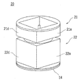
- 2 is a schematic perspective view of a polygon mirror 20 built in the laser scan sensor 100.
- FIG. FIG. 2 is a schematic plan view of an encoder 14 that is attached to the lower part of a polygon mirror 20 and detects its rotational state.
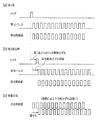
- (A) to (c) are the trigger and projection pulse timing and elapsed time (rotation angle) and projection irradiation surface when the trigger start points of each surface of the light emitting mirror portion 21 of the polygon mirror 20 are aligned. It is the schematic which shows the upper positional relationship.
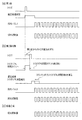
- (A) to (c) are the trigger and projection pulse timing and elapsed time (rotation angle) and projection when the trigger start point after the second surface of the light-emitting mirror portion 21 of the polygon mirror 20 is delayed. It is the schematic which shows the positional relationship etc. on an irradiation surface. (A) to (c) are cases where delay processing is added from the trigger of each surface of the light-emitting mirror section 21 of the polygon mirror 20 to the start of output of the projection pulse train, and when the trigger start points of each surface are aligned. It is the schematic which shows the timing of a trigger, a light projection pulse, elapsed time (rotation angle), the positional relationship on a light projection irradiation surface, etc.
- FIG. 3 is a schematic diagram showing the timing and elapsed time (rotation angle) of a trigger and a light projection pulse, a positional relationship on a light projection irradiation surface, and the like.
- (A) to (c) are cases in which a delay process is added from the trigger of each surface of the light-emitting mirror portion 21 of the polygon mirror 20 to the start of output of the projection pulse train to align the projection start points of each surface.
- FIG. 1 It is a schematic diagram showing the timing and elapsed time (rotation angle) of the trigger and the light projection pulse, the positional relationship on the light projection irradiation surface, etc. when each surface is not curved.
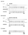
- (A) to (c) are cases in which a delay process is added from the trigger of each surface of the light-emitting mirror portion 21 of the polygon mirror 20 to the start of output of the projection pulse train to align the projection start points of each surface.
- It is the schematic which shows the timing of a trigger, a light projection pulse, elapsed time (rotation angle), the positional relationship on a light projection irradiation surface, etc. when there exists a curvature etc. in at least 1 surface.
- (A) to (c) are cases in which a delay process is added from the trigger of each surface of the light-emitting mirror portion 21 of the polygon mirror 20 to the start of output of the projection pulse train to align the projection start points of each surface.
- Schematic diagram showing the timing and elapsed time (rotation angle) of triggers and light projection pulses, the positional relationship on the light projection irradiation surface, etc. when at least one surface is curved and the pulse period of the light projection pulse train is changed. It is.
- FIG. 1 is a block diagram showing a schematic configuration of a laser scan sensor 100 according to an embodiment of the present invention.
- FIG. 2 is a schematic perspective view of the polygon mirror 20 built in the laser scan sensor 100.
- FIG. 3 is a schematic plan view of the encoder 14 that is attached to the lower part of the polygon mirror 20 and detects the rotational state thereof.
- a laser scan sensor 100 includes a laser light emitting element 11 that emits pulsed laser light, a light receiving element 12 that receives reflected light that is reflected by an object such as a human body, and a pulse laser.
- a polygon mirror 20 that changes the light traveling direction and the light receiving direction of the light receiving element 12, a drive motor 13 that rotates the polygon mirror 20 in a predetermined direction, an encoder 14 that detects the rotational state of the polygon mirror 20, and a connection to these.
- a control arithmetic unit 30 having a memory 30a as well as performing control and arithmetic operations.
- Examples of the laser light emitting element 11 include, but are not limited to, a semiconductor laser diode (LD).
- LD semiconductor laser diode
- Examples of the light receiving element 12 include, but are not limited to, an avalanche photodiode (APD).
- APD avalanche photodiode
- the pulsed laser light emitted from the laser light emitting element 11 reaches an object such as a human body existing outside, and a part of the reflected light reflected by the object returns and reaches the light receiving element 12.
- Distance data to an object such as a human body is obtained by precisely measuring a minute time from when the pulsed laser light is emitted from the laser light emitting element 11 to when the reflected light reaches the light receiving element 12. be able to.
- the polygon mirror 20 has four flat horizontally-oriented rectangular small mirrors 21a, 21b, 21c, and 21d (21b and 21c are not visible in FIG. 2) in this order.
- the light-emitting mirror section 21 arranged in a square cross section and four flat, substantially square-shaped small mirrors 22a, 22b, 22c, and 22d (22b and 22c are not visible in FIG. 2) are directed outward in this order.
- a light receiving mirror section 22 arranged in a square cross section.
- the light-emitting mirror unit 21 and the light-receiving mirror unit 22 have the same rotation axis, and are configured such that the small mirrors 21a, 21b, 21c, and 21d are parallel to the small mirrors 22a, 22b, 22c, and 22d, respectively.
- the polygon mirror 20 is rotated in a predetermined direction at a very fast constant speed by the drive motor 13.
- the pulsed laser light emitted from the laser light emitting element 11 is reflected by one of the small mirrors 21a, 21b, 21c, and 21d of the light emitting mirror unit 21 and changes its traveling direction, it is reflected by an object such as a human body.
- the reflected light of the part returns and is reflected again by one of the small mirrors 22 a, 22 b, 22 c, 22 d of the light receiving mirror part 22 and reaches the light receiving element 12.
- the pulse laser beam is reflected by the small mirror 21a
- the reflected light that has returned is reflected by the small mirror 22a corresponding to the small mirror 21a.
- the small mirrors 21a, 21b, 21c, and 21d change their directions little by little during one light emission period of the pulse laser beam. That is, the direction in which the pulse laser beam is reflected changes at a constant angular interval for each pulse, so that the pulse laser beam can be scanned at a constant angular interval over a wide angular range.
- the encoder 14 is a substantially donut-shaped metal plate having a small central circle and rotates together with the polygon mirror 20 counterclockwise, for example.
- the encoder 14 corresponds to a slit 14x for generating one pulse as a reference signal for each rotation by a photo interrupter (not shown) and the like, and each surface (small mirrors 21a to 21d) of the light-emitting mirror portion 21 of the polygon mirror 20.
- These slit portions 14a to 14d may be a slit group for generating not only a trigger signal but also a pulse signal sequence for driving the laser light emitting element 11.
- the first pulse of the pulse signal sequence is a trigger signal. It may also serve as.
- the slit part 14a generates a pulse signal sequence including a trigger signal corresponding to the small mirror 21a.
- the control arithmetic unit 30 performs light emission control of the laser light emitting element 11, time measurement and recording until the reflected light returns, rotation control of the drive motor 13, and monitoring of a detection signal from the encoder 14.
- Examples of the control arithmetic unit 30 include, but are not limited to, a dedicated hardware circuit and a high-speed arithmetic processing unit in which a control program can be rewritten.
- this control arithmetic unit 30 can determine that the first pulse signal sequence detected after the detection of the reference signal by the slit 14x is due to the slit portion 14a, the laser light emitting element is triggered by the first pulse signal of the pulse signal sequence. 11 starts the output of the light projection pulse train for driving 11. For example, when 380 pulses are output in the range of 90 degrees, the angle per pulse is about 0.25.
- each pulse may be output as it is according to each slit of the slit portion 14a, but a predetermined pulse period (a constant time interval) determined in advance by time management by the control arithmetic unit 30 or the like. ). This is because an error in the formation position of each slit of the slit portion 14a and the influence of the difference from the other slit portions 14b to 14d can be avoided, and this is also adopted in the present embodiment. In this case, other than the first slits of the slit portions 14a to 14d may be omitted.
- the first pulse signal of the pulse signal train is used as a trigger.
- Output of a light projection pulse train for driving the laser light emitting element 11 is started.
- the actual output of the light projection pulse train similarly, it may be output according to each pulse of the pulse signal train by the slit portion 14b, or the second and subsequent light projection pulses may be outputted at a predetermined pulse cycle. Also good.
- FIGS. 4A to 4C show the triggers when the trigger start points on each surface of the light emitting mirror portion 21 of the polygon mirror 20 are aligned.
- FIG. 6 is a schematic diagram showing the timing and elapsed time (rotation angle) of a light projection pulse, the positional relationship on a light projection surface, and the like. In the pulse signal sequence including the trigger, only the first pulse signal is shown, and the second and subsequent pulses are omitted (the same applies to the following drawings).
- control arithmetic unit 30 when the control arithmetic unit 30 detects the first pulse signal of the pulse signal sequence corresponding to the first surface (small mirror 21a), it drives the laser light emitting element 11 using this as a trigger.
- the output of the projection pulse train having a predetermined pulse period is started. This corresponds to the fact that light beams from the pulsed laser light are arranged at regular intervals on the projection irradiation surface.
- the control arithmetic unit 30 detects the first pulse signal in the pulse signal sequence, Using this as a trigger, the output of a projection pulse train of a predetermined pulse period for driving the laser light emitting element 11 is similarly started.
- the trigger start points after the second surface are delayed.
- the first surface (small mirror 21a) is the same as in FIG. 4 (a) as shown in FIG. 5 (a).
- the trigger start point is a standard time difference (slit 14x and slit portion 14a) corresponding to each surface after the generation of the reference signal.
- ⁇ 14d calculated based on the relative positional relationship of each and the rotation speed of the encoder 14), when the output of the light emitting pulse train from the control arithmetic unit 30 is started later Also late.
- the delay for delaying the output start of the projected pulse train on that surface Adjustment is possible by processing.
- the delay time cannot be negative, and adjustment is impossible.
- the first surface which is the reference surface A value that is greater than or equal to the expected delay time is preset as the initial delay time value for each surface, and the actual trigger deviation time is counted (measured) on each surface, and the counted trigger deviation time is calculated.
- FIGS. 6A to 6C show a case where a delay process is added from the trigger of each surface of the light-emitting mirror portion 21 of the polygon mirror 20 to the start of the output of the projection pulse train, and the trigger start point of each surface is It is the schematic which shows the timing of a trigger, a light projection pulse, elapsed time (rotation angle), the positional relationship on a light projection irradiation surface, etc. when it has gathered.
- the trigger start points of each surface are originally aligned, and the trigger deviation time is 0 second for each surface.
- the delay time until the start of pulse train output remains the initial value.
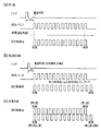
- FIGS. 7A to 7C show a case where a delay process is added from the trigger of each surface of the light-emitting mirror portion 21 of the polygon mirror 20 to the start of output of the projection pulse train, and the trigger start on the second and subsequent surfaces. It is the schematic which shows the timing of a trigger or a light projection pulse, the elapsed time (rotation angle), the positional relationship on a light projection irradiation surface, etc. when the point is late.
- the first surface (small mirror 21a) is the same as in FIG. 6 (a) as shown in FIG. 7 (a).
- the trigger start point is later than the timing at which the standard time difference corresponding to each surface has elapsed after the generation of the reference signal (when triggering on each surface).
- the trigger deviation time (X seconds) is counted, and the delay time of the surface is corrected as follows.
- each surface of the polygon mirror 20 set by the encoder 14 or the like is set by appropriately setting the delay time from the trigger to the start of output of the projection pulse train on each surface of the light-emitting mirror unit 21 of the polygon mirror 20. Even if the projection start trigger is shifted with respect to the other surface, the actual projection irradiation surface can be aligned.
- the delay time of each surface is stored in the memory in the control arithmetic unit 30 after subtracting the trigger deviation time counted by the control arithmetic unit 30 from the initial value of the delay time at the time of adjustment before shipment at the factory.
- the delay time of each surface stored in the memory may be referred to.
- the trigger timing set due to the influence of the eccentricity of the shaft of the drive motor 13 due to, for example, an external factor (for example, an impact such as a drop) shifts, and the projection irradiation timing or the projection irradiation
- the position of each light beam on the surface may shift.
- the trigger deviation time counted by the control arithmetic unit 30 is used by subtracting it from the delay time of each surface stored in the memory, and the memory content is updated (stored as the latest delay time). ).
- the trigger timing of each surface is shifted due to an external factor or the like, it is possible to automatically correct.
- the terminal end side of the light beam on the projection irradiation surface may not be aligned.
- FIGS. 8A to 8C show projections from triggers on each surface of the light-emitting mirror portion 21 of the polygon mirror 20.
- delay processing is added before the start of pulse train output and the projection start points of each surface are aligned, the timing and elapsed time (rotation angle) of triggers and projection pulses when there is no curvature on each surface, It is the schematic which shows the positional relationship etc. on a light projection irradiation surface.
- the first surface (small mirror 21a) is the same as in FIG. 7 (a) as shown in FIG. 8 (a).
- the second and subsequent surfaces are the same as in FIG. 7B as shown in FIG. 8B.
- FIG. 6 is a schematic diagram showing the timing and elapsed time (rotation angle) of the trigger and the light projection pulse, the positional relationship on the light projection irradiation surface, and the like when at least one surface is curved.
- the light projection start point and the light projection end point of the light projection pulse train on that surface are both the first surface and the first surface. Even if they are the same, the terminal position of the light beam may be different from the first surface on the projection irradiation surface.
- the first surface (small mirror 21a) is the same as in FIG. 9 (a) as shown in FIG. 10 (a).
- the light projection start point and the light projection end point on the surface are both the first surface and the first surface. Even if they are the same, the termination position of the light beam may be different from that of the first surface on the projection irradiation surface, as in FIG. 9B.
- the delay time of each surface described above may be readjusted, but this will cause the tip side of the light beam to shift again.
- adjustment is performed to move the end position of the light beam by increasing or decreasing the pulse period of the light projection pulse train.
- actual pulsed laser light is projected onto a white surface or the like, the front end and the end of the light beam on each surface are visually recognized, and the delay time of each surface is readjusted so that the end ends are aligned.
- the tip of the light beam on each surface may be shifted again.
- the delay time is returned before the readjustment, and a value obtained by dividing the difference in the delay time changed at the readjustment by the number of pulses of the projection pulse train is reflected in the pulse cycle (increase / decrease the pulse cycle).
- the output end timing of the projection pulse train changes, but the output start timing does not change. It is preferable that the pulse width is not changed.
- the pulse period of the projection pulse train is appropriately set on each surface of the light-emitting mirror portion 21 of the polygon mirror 20, so that the polygon mirror 20 Even if there is a curvature or the like on each surface, it is possible to align the actual projection irradiation surface.
Landscapes
- Physics & Mathematics (AREA)
- Engineering & Computer Science (AREA)
- General Physics & Mathematics (AREA)
- Computer Networks & Wireless Communication (AREA)
- Radar, Positioning & Navigation (AREA)
- Remote Sensing (AREA)
- Optics & Photonics (AREA)
- Electromagnetism (AREA)
- Optical Radar Systems And Details Thereof (AREA)
- Mechanical Optical Scanning Systems (AREA)
- Facsimile Scanning Arrangements (AREA)
Abstract
La présente invention concerne un capteur à balayage laser (100) qui est pourvu de : un élément d'émission de lumière laser (11) pour émettre une lumière laser pulsée; un élément de réception de lumière (12) pour recevoir la lumière réfléchie qui est retournée; un miroir polygonal (20) comportant une pluralité de surfaces réfléchissantes pour modifier la direction d'avancement de la lumière laser pulsée; un moteur d'entraînement (13) pour faire tourner le miroir polygonal (20) dans une direction prescrite; un codeur (14) pour détecter l'état de rotation du miroir polygonal (20) et générer un signal de référence et des signaux de déclenchement correspondant à chacune des surfaces réfléchissantes; et une unité de calcul de commande (30) pour délivrer en sortie une chaîne d'impulsions de projection d'un cycle d'impulsion prescrit après l'écoulement d'un temps de retard correspondant après la génération d'un signal de déclenchement, et l'acquisition d'informations de distance sur la base de la durée, pour chaque impulsion, depuis le début de l'émission de lumière jusqu'à ce que la lumière réfléchie retourne; le temps de retard étant respectivement défini pour chaque surface réfléchissante.
Priority Applications (3)
| Application Number | Priority Date | Filing Date | Title |
|---|---|---|---|
| US16/312,386 US11531092B2 (en) | 2016-06-23 | 2017-08-07 | Laser scanning sensor |
| EP17814826.8A EP3477332B1 (fr) | 2016-06-23 | 2017-08-07 | Capteur à balayage laser |
| PCT/IB2017/000922 WO2017221071A1 (fr) | 2016-06-23 | 2017-08-07 | Capteur à balayage laser |
Applications Claiming Priority (3)
| Application Number | Priority Date | Filing Date | Title |
|---|---|---|---|
| JP2016-124867 | 2016-06-23 | ||
| JP2016124867A JP6831550B2 (ja) | 2016-06-23 | 2016-06-23 | レーザースキャンセンサ |
| PCT/IB2017/000922 WO2017221071A1 (fr) | 2016-06-23 | 2017-08-07 | Capteur à balayage laser |
Publications (1)
| Publication Number | Publication Date |
|---|---|
| WO2017221071A1 true WO2017221071A1 (fr) | 2017-12-28 |
Family
ID=60784429
Family Applications (1)
| Application Number | Title | Priority Date | Filing Date |
|---|---|---|---|
| PCT/IB2017/000922 Ceased WO2017221071A1 (fr) | 2016-06-23 | 2017-08-07 | Capteur à balayage laser |
Country Status (4)
| Country | Link |
|---|---|
| US (1) | US11531092B2 (fr) |
| EP (1) | EP3477332B1 (fr) |
| JP (1) | JP6831550B2 (fr) |
| WO (1) | WO2017221071A1 (fr) |
Families Citing this family (11)
| Publication number | Priority date | Publication date | Assignee | Title |
|---|---|---|---|---|
| USD871412S1 (en) * | 2016-11-21 | 2019-12-31 | Datalogic Ip Tech S.R.L. | Optical scanner |
| JP7078061B2 (ja) * | 2017-12-22 | 2022-05-31 | コニカミノルタ株式会社 | 光走査装置、光走査装置の制御方法、および光走査装置の制御プログラム |
| US10591598B2 (en) | 2018-01-08 | 2020-03-17 | SOS Lab co., Ltd | Lidar device |
| WO2019135494A1 (fr) * | 2018-01-08 | 2019-07-11 | 주식회사 에스오에스랩 | Dispositif lidar |
| JP7087633B2 (ja) * | 2018-04-26 | 2022-06-21 | コニカミノルタ株式会社 | ライダー、およびライダーの制御方法 |
| KR102050599B1 (ko) | 2018-05-14 | 2019-12-02 | 주식회사 에스오에스랩 | 라이다 장치 |
| WO2020193313A1 (fr) * | 2019-03-22 | 2020-10-01 | Ams International Ag | Calculateur de temps de vol à distance |
| KR102281886B1 (ko) | 2019-09-05 | 2021-07-26 | 주식회사 에스오에스랩 | 라이다 장치 |
| KR102882118B1 (ko) * | 2022-03-15 | 2025-11-12 | 주식회사 에이치엘클레무브 | 다면 미러 회전식 라이다의 왜곡 보정 장치 및 방법 |
| WO2024070180A1 (fr) | 2022-09-27 | 2024-04-04 | オプテックス株式会社 | Capteur de balayage |
| DE102024120324A1 (de) * | 2024-07-18 | 2026-01-22 | Valeo Detection Systems GmbH | Verfahren zur kalibrierung eines optischen sensorsystems und optisches sensorsystem |
Citations (4)
| Publication number | Priority date | Publication date | Assignee | Title |
|---|---|---|---|---|
| JPH1184006A (ja) * | 1997-07-18 | 1999-03-26 | Denso Corp | 車載レーダ装置 |
| EP1619469A1 (fr) * | 2004-07-22 | 2006-01-25 | Bea S.A. | Dispositif de balayage et détection à laser pour détection autour des portes automatiques |
| JP2012083559A (ja) * | 2010-10-12 | 2012-04-26 | Konica Minolta Business Technologies Inc | 画像形成装置及び画像形成装置制御方法 |
| JP2016070974A (ja) * | 2014-09-26 | 2016-05-09 | 株式会社デンソー | レーザ照射制御装置 |
Family Cites Families (5)
| Publication number | Priority date | Publication date | Assignee | Title |
|---|---|---|---|---|
| US4441126A (en) * | 1982-05-06 | 1984-04-03 | Sperry Corporation | Adaptive corrector of facet errors in mirror scanning systems |
| JP2946793B2 (ja) * | 1991-03-19 | 1999-09-06 | ブラザー工業株式会社 | 光偏向器 |
| US7869112B2 (en) * | 2008-07-25 | 2011-01-11 | Prysm, Inc. | Beam scanning based on two-dimensional polygon scanner for display and other applications |
| JP5439684B2 (ja) | 2009-07-17 | 2014-03-12 | オプテックス株式会社 | レーザスキャンセンサ |
| JP5540217B2 (ja) | 2012-09-19 | 2014-07-02 | オプテックス株式会社 | レーザースキャンセンサ |
-
2016
- 2016-06-23 JP JP2016124867A patent/JP6831550B2/ja active Active
-
2017
- 2017-08-07 US US16/312,386 patent/US11531092B2/en active Active
- 2017-08-07 EP EP17814826.8A patent/EP3477332B1/fr active Active
- 2017-08-07 WO PCT/IB2017/000922 patent/WO2017221071A1/fr not_active Ceased
Patent Citations (4)
| Publication number | Priority date | Publication date | Assignee | Title |
|---|---|---|---|---|
| JPH1184006A (ja) * | 1997-07-18 | 1999-03-26 | Denso Corp | 車載レーダ装置 |
| EP1619469A1 (fr) * | 2004-07-22 | 2006-01-25 | Bea S.A. | Dispositif de balayage et détection à laser pour détection autour des portes automatiques |
| JP2012083559A (ja) * | 2010-10-12 | 2012-04-26 | Konica Minolta Business Technologies Inc | 画像形成装置及び画像形成装置制御方法 |
| JP2016070974A (ja) * | 2014-09-26 | 2016-05-09 | 株式会社デンソー | レーザ照射制御装置 |
Non-Patent Citations (1)
| Title |
|---|
| See also references of EP3477332A4 * |
Also Published As
| Publication number | Publication date |
|---|---|
| EP3477332B1 (fr) | 2022-10-05 |
| US11531092B2 (en) | 2022-12-20 |
| US20190235060A1 (en) | 2019-08-01 |
| JP2017227569A (ja) | 2017-12-28 |
| EP3477332A1 (fr) | 2019-05-01 |
| JP6831550B2 (ja) | 2021-02-17 |
| EP3477332A4 (fr) | 2020-03-04 |
Similar Documents
| Publication | Publication Date | Title |
|---|---|---|
| WO2017221071A1 (fr) | Capteur à balayage laser | |
| KR20190058331A (ko) | 폴리곤 스캐너 및 모니터링 영역 내의 물체들을 검출하기 위한 방법 | |
| US8643828B2 (en) | Laser surveying instrument | |
| JPWO2016056545A1 (ja) | 走査光学系及び投受光装置 | |
| US20210336566A1 (en) | Ranging apparatus and scan mechanism thereof, control method, and mobile platform | |
| US20090279156A1 (en) | Mems scan controller with inherent frequency and method of control thereof | |
| JP2015132599A (ja) | 光電センサ及び監視領域内の物体の検出方法 | |
| KR102359132B1 (ko) | 라이다 스캐너 | |
| JP2018005183A (ja) | 光走査装置、物体検知装置および距離検知装置 | |
| CN114365006B (zh) | 激光扫描仪 | |
| KR102105715B1 (ko) | 라이다 스캐너 | |
| JP7416647B2 (ja) | 測量装置 | |
| JP7087633B2 (ja) | ライダー、およびライダーの制御方法 | |
| WO2019123722A1 (fr) | Dispositif de balayage optique, procédé de commande de dispositif de balayage optique et programme de commande de dispositif de balayage optique | |
| JP2022023608A5 (fr) | ||
| JP2014194380A (ja) | レーザ測定装置 | |
| JP2014071028A (ja) | レーザレーダ装置 | |
| CN110068807B (zh) | 机载激光雷达脉冲速率调制 | |
| US10823955B2 (en) | Grating-based spatial mode filter for laser scanning | |
| CN115685140A (zh) | 测量装置 | |
| JPWO2018008393A1 (ja) | レーザーレーダー装置 | |
| US20230078949A1 (en) | Airborne laser scanner | |
| US12055660B2 (en) | Polygon scanning mirror for lidar beam scanning | |
| CN114341664A (zh) | 光测距装置 | |
| JP3418903B2 (ja) | 光走査装置 |
Legal Events
| Date | Code | Title | Description |
|---|---|---|---|
| 121 | Ep: the epo has been informed by wipo that ep was designated in this application |
Ref document number: 17814826 Country of ref document: EP Kind code of ref document: A1 |
|
| NENP | Non-entry into the national phase |
Ref country code: DE |
|
| ENP | Entry into the national phase |
Ref document number: 2017814826 Country of ref document: EP Effective date: 20190123 |