WO2018016423A1 - セラミック-金属構造体 - Google Patents
セラミック-金属構造体 Download PDFInfo
- Publication number
- WO2018016423A1 WO2018016423A1 PCT/JP2017/025642 JP2017025642W WO2018016423A1 WO 2018016423 A1 WO2018016423 A1 WO 2018016423A1 JP 2017025642 W JP2017025642 W JP 2017025642W WO 2018016423 A1 WO2018016423 A1 WO 2018016423A1
- Authority
- WO
- WIPO (PCT)
- Prior art keywords
- ceramic
- ring member
- metal structure
- pad layer
- metal
- Prior art date
- Legal status (The legal status is an assumption and is not a legal conclusion. Google has not performed a legal analysis and makes no representation as to the accuracy of the status listed.)
- Ceased
Links
Images

Classifications
-
- B—PERFORMING OPERATIONS; TRANSPORTING
- B23—MACHINE TOOLS; METAL-WORKING NOT OTHERWISE PROVIDED FOR
- B23K—SOLDERING OR UNSOLDERING; WELDING; CLADDING OR PLATING BY SOLDERING OR WELDING; CUTTING BY APPLYING HEAT LOCALLY, e.g. FLAME CUTTING; WORKING BY LASER BEAM
- B23K1/00—Soldering, e.g. brazing, or unsoldering
- B23K1/14—Soldering, e.g. brazing, or unsoldering specially adapted for soldering seams
-
- B—PERFORMING OPERATIONS; TRANSPORTING
- B23—MACHINE TOOLS; METAL-WORKING NOT OTHERWISE PROVIDED FOR
- B23K—SOLDERING OR UNSOLDERING; WELDING; CLADDING OR PLATING BY SOLDERING OR WELDING; CUTTING BY APPLYING HEAT LOCALLY, e.g. FLAME CUTTING; WORKING BY LASER BEAM
- B23K1/00—Soldering, e.g. brazing, or unsoldering
- B23K1/14—Soldering, e.g. brazing, or unsoldering specially adapted for soldering seams
- B23K1/18—Soldering, e.g. brazing, or unsoldering specially adapted for soldering seams circumferential seams, e.g. of shells
-
- B—PERFORMING OPERATIONS; TRANSPORTING
- B23—MACHINE TOOLS; METAL-WORKING NOT OTHERWISE PROVIDED FOR
- B23K—SOLDERING OR UNSOLDERING; WELDING; CLADDING OR PLATING BY SOLDERING OR WELDING; CUTTING BY APPLYING HEAT LOCALLY, e.g. FLAME CUTTING; WORKING BY LASER BEAM
- B23K1/00—Soldering, e.g. brazing, or unsoldering
- B23K1/19—Soldering, e.g. brazing, or unsoldering taking account of the properties of the materials to be soldered
-
- C—CHEMISTRY; METALLURGY
- C04—CEMENTS; CONCRETE; ARTIFICIAL STONE; CERAMICS; REFRACTORIES
- C04B—LIME, MAGNESIA; SLAG; CEMENTS; COMPOSITIONS THEREOF, e.g. MORTARS, CONCRETE OR LIKE BUILDING MATERIALS; ARTIFICIAL STONE; CERAMICS; REFRACTORIES; TREATMENT OF NATURAL STONE
- C04B37/00—Joining burned ceramic articles with other burned ceramic articles or other articles by heating
- C04B37/02—Joining burned ceramic articles with other burned ceramic articles or other articles by heating with metallic articles
-
- C—CHEMISTRY; METALLURGY
- C04—CEMENTS; CONCRETE; ARTIFICIAL STONE; CERAMICS; REFRACTORIES
- C04B—LIME, MAGNESIA; SLAG; CEMENTS; COMPOSITIONS THEREOF, e.g. MORTARS, CONCRETE OR LIKE BUILDING MATERIALS; ARTIFICIAL STONE; CERAMICS; REFRACTORIES; TREATMENT OF NATURAL STONE
- C04B37/00—Joining burned ceramic articles with other burned ceramic articles or other articles by heating
- C04B37/02—Joining burned ceramic articles with other burned ceramic articles or other articles by heating with metallic articles
- C04B37/023—Joining burned ceramic articles with other burned ceramic articles or other articles by heating with metallic articles characterised by the interlayer used
-
- B—PERFORMING OPERATIONS; TRANSPORTING
- B23—MACHINE TOOLS; METAL-WORKING NOT OTHERWISE PROVIDED FOR
- B23K—SOLDERING OR UNSOLDERING; WELDING; CLADDING OR PLATING BY SOLDERING OR WELDING; CUTTING BY APPLYING HEAT LOCALLY, e.g. FLAME CUTTING; WORKING BY LASER BEAM
- B23K2103/00—Materials to be soldered, welded or cut
- B23K2103/02—Iron or ferrous alloys
- B23K2103/04—Steel or steel alloys
- B23K2103/05—Stainless steel
-
- B—PERFORMING OPERATIONS; TRANSPORTING
- B23—MACHINE TOOLS; METAL-WORKING NOT OTHERWISE PROVIDED FOR
- B23K—SOLDERING OR UNSOLDERING; WELDING; CLADDING OR PLATING BY SOLDERING OR WELDING; CUTTING BY APPLYING HEAT LOCALLY, e.g. FLAME CUTTING; WORKING BY LASER BEAM
- B23K2103/00—Materials to be soldered, welded or cut
- B23K2103/50—Inorganic materials other than metals or composite materials
- B23K2103/52—Ceramics
-
- C—CHEMISTRY; METALLURGY
- C04—CEMENTS; CONCRETE; ARTIFICIAL STONE; CERAMICS; REFRACTORIES
- C04B—LIME, MAGNESIA; SLAG; CEMENTS; COMPOSITIONS THEREOF, e.g. MORTARS, CONCRETE OR LIKE BUILDING MATERIALS; ARTIFICIAL STONE; CERAMICS; REFRACTORIES; TREATMENT OF NATURAL STONE
- C04B2237/00—Aspects relating to ceramic laminates or to joining of ceramic articles with other articles by heating
- C04B2237/02—Aspects relating to interlayers, e.g. used to join ceramic articles with other articles by heating
- C04B2237/04—Ceramic interlayers
- C04B2237/06—Oxidic interlayers
- C04B2237/064—Oxidic interlayers based on alumina or aluminates
-
- C—CHEMISTRY; METALLURGY
- C04—CEMENTS; CONCRETE; ARTIFICIAL STONE; CERAMICS; REFRACTORIES
- C04B—LIME, MAGNESIA; SLAG; CEMENTS; COMPOSITIONS THEREOF, e.g. MORTARS, CONCRETE OR LIKE BUILDING MATERIALS; ARTIFICIAL STONE; CERAMICS; REFRACTORIES; TREATMENT OF NATURAL STONE
- C04B2237/00—Aspects relating to ceramic laminates or to joining of ceramic articles with other articles by heating
- C04B2237/02—Aspects relating to interlayers, e.g. used to join ceramic articles with other articles by heating
- C04B2237/12—Metallic interlayers
- C04B2237/122—Metallic interlayers based on refractory metals
-
- C—CHEMISTRY; METALLURGY
- C04—CEMENTS; CONCRETE; ARTIFICIAL STONE; CERAMICS; REFRACTORIES
- C04B—LIME, MAGNESIA; SLAG; CEMENTS; COMPOSITIONS THEREOF, e.g. MORTARS, CONCRETE OR LIKE BUILDING MATERIALS; ARTIFICIAL STONE; CERAMICS; REFRACTORIES; TREATMENT OF NATURAL STONE
- C04B2237/00—Aspects relating to ceramic laminates or to joining of ceramic articles with other articles by heating
- C04B2237/02—Aspects relating to interlayers, e.g. used to join ceramic articles with other articles by heating
- C04B2237/12—Metallic interlayers
- C04B2237/124—Metallic interlayers based on copper
-
- C—CHEMISTRY; METALLURGY
- C04—CEMENTS; CONCRETE; ARTIFICIAL STONE; CERAMICS; REFRACTORIES
- C04B—LIME, MAGNESIA; SLAG; CEMENTS; COMPOSITIONS THEREOF, e.g. MORTARS, CONCRETE OR LIKE BUILDING MATERIALS; ARTIFICIAL STONE; CERAMICS; REFRACTORIES; TREATMENT OF NATURAL STONE
- C04B2237/00—Aspects relating to ceramic laminates or to joining of ceramic articles with other articles by heating
- C04B2237/02—Aspects relating to interlayers, e.g. used to join ceramic articles with other articles by heating
- C04B2237/12—Metallic interlayers
- C04B2237/125—Metallic interlayers based on noble metals, e.g. silver
-
- C—CHEMISTRY; METALLURGY
- C04—CEMENTS; CONCRETE; ARTIFICIAL STONE; CERAMICS; REFRACTORIES
- C04B—LIME, MAGNESIA; SLAG; CEMENTS; COMPOSITIONS THEREOF, e.g. MORTARS, CONCRETE OR LIKE BUILDING MATERIALS; ARTIFICIAL STONE; CERAMICS; REFRACTORIES; TREATMENT OF NATURAL STONE
- C04B2237/00—Aspects relating to ceramic laminates or to joining of ceramic articles with other articles by heating
- C04B2237/30—Composition of layers of ceramic laminates or of ceramic or metallic articles to be joined by heating, e.g. Si substrates
- C04B2237/32—Ceramic
- C04B2237/34—Oxidic
- C04B2237/343—Alumina or aluminates
-
- C—CHEMISTRY; METALLURGY
- C04—CEMENTS; CONCRETE; ARTIFICIAL STONE; CERAMICS; REFRACTORIES
- C04B—LIME, MAGNESIA; SLAG; CEMENTS; COMPOSITIONS THEREOF, e.g. MORTARS, CONCRETE OR LIKE BUILDING MATERIALS; ARTIFICIAL STONE; CERAMICS; REFRACTORIES; TREATMENT OF NATURAL STONE
- C04B2237/00—Aspects relating to ceramic laminates or to joining of ceramic articles with other articles by heating
- C04B2237/30—Composition of layers of ceramic laminates or of ceramic or metallic articles to be joined by heating, e.g. Si substrates
- C04B2237/40—Metallic
- C04B2237/405—Iron metal group, e.g. Co or Ni
- C04B2237/406—Iron, e.g. steel
-
- C—CHEMISTRY; METALLURGY
- C04—CEMENTS; CONCRETE; ARTIFICIAL STONE; CERAMICS; REFRACTORIES
- C04B—LIME, MAGNESIA; SLAG; CEMENTS; COMPOSITIONS THEREOF, e.g. MORTARS, CONCRETE OR LIKE BUILDING MATERIALS; ARTIFICIAL STONE; CERAMICS; REFRACTORIES; TREATMENT OF NATURAL STONE
- C04B2237/00—Aspects relating to ceramic laminates or to joining of ceramic articles with other articles by heating
- C04B2237/50—Processing aspects relating to ceramic laminates or to the joining of ceramic articles with other articles by heating
- C04B2237/62—Forming laminates or joined articles comprising holes, channels or other types of openings
-
- C—CHEMISTRY; METALLURGY
- C04—CEMENTS; CONCRETE; ARTIFICIAL STONE; CERAMICS; REFRACTORIES
- C04B—LIME, MAGNESIA; SLAG; CEMENTS; COMPOSITIONS THEREOF, e.g. MORTARS, CONCRETE OR LIKE BUILDING MATERIALS; ARTIFICIAL STONE; CERAMICS; REFRACTORIES; TREATMENT OF NATURAL STONE
- C04B2237/00—Aspects relating to ceramic laminates or to joining of ceramic articles with other articles by heating
- C04B2237/50—Processing aspects relating to ceramic laminates or to the joining of ceramic articles with other articles by heating
- C04B2237/68—Forming laminates or joining articles wherein at least one substrate contains at least two different parts of macro-size, e.g. one ceramic substrate layer containing an embedded conductor or electrode
-
- C—CHEMISTRY; METALLURGY
- C04—CEMENTS; CONCRETE; ARTIFICIAL STONE; CERAMICS; REFRACTORIES
- C04B—LIME, MAGNESIA; SLAG; CEMENTS; COMPOSITIONS THEREOF, e.g. MORTARS, CONCRETE OR LIKE BUILDING MATERIALS; ARTIFICIAL STONE; CERAMICS; REFRACTORIES; TREATMENT OF NATURAL STONE
- C04B2237/00—Aspects relating to ceramic laminates or to joining of ceramic articles with other articles by heating
- C04B2237/50—Processing aspects relating to ceramic laminates or to the joining of ceramic articles with other articles by heating
- C04B2237/72—Forming laminates or joined articles comprising at least two interlayers directly next to each other
-
- C—CHEMISTRY; METALLURGY
- C04—CEMENTS; CONCRETE; ARTIFICIAL STONE; CERAMICS; REFRACTORIES
- C04B—LIME, MAGNESIA; SLAG; CEMENTS; COMPOSITIONS THEREOF, e.g. MORTARS, CONCRETE OR LIKE BUILDING MATERIALS; ARTIFICIAL STONE; CERAMICS; REFRACTORIES; TREATMENT OF NATURAL STONE
- C04B2237/00—Aspects relating to ceramic laminates or to joining of ceramic articles with other articles by heating
- C04B2237/50—Processing aspects relating to ceramic laminates or to the joining of ceramic articles with other articles by heating
- C04B2237/74—Forming laminates or joined articles comprising at least two different interlayers separated by a substrate
-
- C—CHEMISTRY; METALLURGY
- C04—CEMENTS; CONCRETE; ARTIFICIAL STONE; CERAMICS; REFRACTORIES
- C04B—LIME, MAGNESIA; SLAG; CEMENTS; COMPOSITIONS THEREOF, e.g. MORTARS, CONCRETE OR LIKE BUILDING MATERIALS; ARTIFICIAL STONE; CERAMICS; REFRACTORIES; TREATMENT OF NATURAL STONE
- C04B2237/00—Aspects relating to ceramic laminates or to joining of ceramic articles with other articles by heating
- C04B2237/50—Processing aspects relating to ceramic laminates or to the joining of ceramic articles with other articles by heating
- C04B2237/76—Forming laminates or joined articles comprising at least one member in the form other than a sheet or disc, e.g. two tubes or a tube and a sheet or disc
- C04B2237/765—Forming laminates or joined articles comprising at least one member in the form other than a sheet or disc, e.g. two tubes or a tube and a sheet or disc at least one member being a tube
-
- C—CHEMISTRY; METALLURGY
- C04—CEMENTS; CONCRETE; ARTIFICIAL STONE; CERAMICS; REFRACTORIES
- C04B—LIME, MAGNESIA; SLAG; CEMENTS; COMPOSITIONS THEREOF, e.g. MORTARS, CONCRETE OR LIKE BUILDING MATERIALS; ARTIFICIAL STONE; CERAMICS; REFRACTORIES; TREATMENT OF NATURAL STONE
- C04B2237/00—Aspects relating to ceramic laminates or to joining of ceramic articles with other articles by heating
- C04B2237/50—Processing aspects relating to ceramic laminates or to the joining of ceramic articles with other articles by heating
- C04B2237/80—Joining the largest surface of one substrate with a smaller surface of the other substrate, e.g. butt joining or forming a T-joint
-
- C—CHEMISTRY; METALLURGY
- C04—CEMENTS; CONCRETE; ARTIFICIAL STONE; CERAMICS; REFRACTORIES
- C04B—LIME, MAGNESIA; SLAG; CEMENTS; COMPOSITIONS THEREOF, e.g. MORTARS, CONCRETE OR LIKE BUILDING MATERIALS; ARTIFICIAL STONE; CERAMICS; REFRACTORIES; TREATMENT OF NATURAL STONE
- C04B2237/00—Aspects relating to ceramic laminates or to joining of ceramic articles with other articles by heating
- C04B2237/50—Processing aspects relating to ceramic laminates or to the joining of ceramic articles with other articles by heating
- C04B2237/86—Joining of two substrates at their largest surfaces, one surface being complete joined and covered, the other surface not, e.g. a small plate joined at it's largest surface on top of a larger plate
-
- Y—GENERAL TAGGING OF NEW TECHNOLOGICAL DEVELOPMENTS; GENERAL TAGGING OF CROSS-SECTIONAL TECHNOLOGIES SPANNING OVER SEVERAL SECTIONS OF THE IPC; TECHNICAL SUBJECTS COVERED BY FORMER USPC CROSS-REFERENCE ART COLLECTIONS [XRACs] AND DIGESTS
- Y10—TECHNICAL SUBJECTS COVERED BY FORMER USPC
- Y10T—TECHNICAL SUBJECTS COVERED BY FORMER US CLASSIFICATION
- Y10T428/00—Stock material or miscellaneous articles
- Y10T428/21—Circular sheet or circular blank
- Y10T428/218—Aperture containing
-
- Y—GENERAL TAGGING OF NEW TECHNOLOGICAL DEVELOPMENTS; GENERAL TAGGING OF CROSS-SECTIONAL TECHNOLOGIES SPANNING OVER SEVERAL SECTIONS OF THE IPC; TECHNICAL SUBJECTS COVERED BY FORMER USPC CROSS-REFERENCE ART COLLECTIONS [XRACs] AND DIGESTS
- Y10—TECHNICAL SUBJECTS COVERED BY FORMER USPC
- Y10T—TECHNICAL SUBJECTS COVERED BY FORMER US CLASSIFICATION
- Y10T428/00—Stock material or miscellaneous articles
- Y10T428/24—Structurally defined web or sheet [e.g., overall dimension, etc.]
- Y10T428/24273—Structurally defined web or sheet [e.g., overall dimension, etc.] including aperture
- Y10T428/24322—Composite web or sheet
- Y10T428/24331—Composite web or sheet including nonapertured component
Definitions
- the present invention relates to a ceramic-metal structure in which a ceramic and a metal are brazed.
- Patent Document 1 a technique is known in which a flange made of Kovar is brazed to ceramic, for example, and a metal pipe part is connected to the flange 2 with a silver solder (Patent Document 1).
- Patent Document 1 a technique is known in which a flange made of Kovar is brazed to ceramic, for example, and a metal pipe part is connected to the flange 2 with a silver solder.
- Patent Document 1 a groove is provided at the end of the pipe part and the molten brazing material is dammed up by this groove, so that the brazing material does not flow into unnecessary portions and the brazing material is concentrated at the brazing location. And can be brazed firmly.
- an object of the present invention is to provide a ceramic-metal structure that can prevent brazing from being peeled off at the time of cooling or cracks in a ceramic substrate and can ensure brazing.
- the ceramic-metal structure of the present invention is such that a pipe-shaped or rod-shaped metal body is inserted into a through-hole penetrating in the thickness direction of the ceramic substrate from the surface of the ceramic substrate.
- a ceramic-metal structure that is coaxially disposed immediately above the through-hole, and is disposed around the through-hole in the surface of the ceramic base, and is made of an annular metal A pad layer, an annular ring member bonded to the pad layer via a first row portion and having a smaller thermal expansion coefficient than the metal body, and between the ring member and the metal body A second row part interposed between the ring member and the metal body, and a pad of the outer surface of the pad layer so as to expose a central region of an upper surface facing the first row part.
- a low flow prevention layer that covers an outer surface of the low flow prevention layer, wherein the first row portion joins the central region and the ring member without protruding to a radially inner side and a radial outer side of the low flow prevention layer. It is characterized by becoming.
- the first row portion does not protrude radially inward and radially outward of the low flow preventing layer, so that the first row portion can be prevented from coming into direct contact with the ceramic base.
- the low flow prevention layer covers the outer surface of the pad layer so as to expose the central region of the upper surface facing the first low portion, and this low flow prevention layer is disposed on the surface of the ceramic substrate.
- the pad layer is formed so as to be in contact with the surface of the ceramic substrate so as to cover the inner and outer peripheral surfaces of the pad layer.
- the low flow prevention layer is disposed on the interface between the most stressed ceramic substrate and the metal pad layer, and the strength is improved. Further, the end of the first row portion is disposed on the inner side of the interface. As a result, the stress applied to the interface is relaxed. As a result, the occurrence of cracks in the ceramic substrate can be suppressed and brazing can be ensured.
- the outer diameter of the ring member is smaller than the outer diameter of the pad layer, and the first row portion is in contact with the outer peripheral surface of the ring member.
- the first row portion has a fillet-shaped (concave) portion, it indicates that the molten row has penetrated between the ring member and the pad layer with sufficient wettability, and the brazing strength is improved.
- the first row portion may have a portion that extends radially inward of the ring member and has a fillet shape. This part also has a fillet shape, so that brazing strength is improved.
- the ceramic base and the brazing material flow preventing layer may be composed mainly of the same material. According to this ceramic-metal structure, since the main components of the ceramic base and the brazing material flow prevention layer are the same material, the adhesion between them is excellent.
- a flow path is formed in the ceramic substrate, the flow path being connected to the through-hole and through which gas flows.
- the metal body is pipe-shaped, and the metal body It may be possible to exchange gas between the flow path and the outside of the ceramic substrate through the inside of the ceramic substrate.
- the ceramic base and the metal body are securely brazed. Gas leakage from the brazed portion can be suppressed, and gas can be exchanged stably.
- FIG. 1 is an exploded perspective view of a ceramic-metal structure according to an embodiment of the present invention.
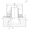
- FIG. 2 is a cross-sectional view taken along line AA in FIG.
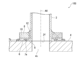
- FIG. 6 is a cross-sectional view showing a modification of the ceramic-metal structure according to the embodiment of the present invention.
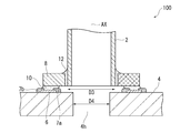
- FIG. 6 is a cross-sectional view showing another modified example of the ceramic-metal structure according to the embodiment of the present invention.
- FIG. 1 is an exploded perspective view of a ceramic-metal structure 100 according to an embodiment of the present invention
- FIG. 2 is a cross-sectional view taken along line AA of FIG.
- a ceramic-metal structure 100 includes a pipe-shaped metal body 2, a substantially rectangular ceramic base 4 having a through-hole 4h, and a pad disposed around the through-hole 4h on the surface of the ceramic base 4.
- Layer 6 low flow prevention layers 7 a and 7 b, which will be described in detail later, ring member 8 that forms an annular shape, first row portion 10 that joins pad layer 6 and ring member 8, ring member 8, and metal body 2. And a second row portion 12 for joining together.
- the ceramic substrate 4 is a ceramic sintered body mainly composed of alumina, and the metal body 2 is formed of stainless steel.
- the pad layer 6 is made of a metal and has an annular shape to improve the adhesion between the ceramic base 4 and the first row part 10 and to prevent the first row part 10 from being in direct contact with the ceramic base 4 and being brazed.
- the pad layer 6 can be formed, for example, by printing a paste mainly composed of at least one of tungsten and molybdenum on the surface of the unfired body of the ceramic substrate 4, firing it, and further plating the surface with Ni.
- the low flow preventing layers 7a and 7b are formed so that, for example, a paste of a material whose main component is the same as that of the ceramic base 4 (alumina in this example) is sandwiched between the green bodies of the ceramic base 4 and the pad layer 6 respectively. After printing in a ring shape, it can be formed by simultaneous firing with the ceramic substrate 4 and the pad layer 6.
- the ring member 8 is formed of, for example, kovar having a smaller coefficient of thermal expansion than that of the metal body 2.
- Au—Cu alloy, Ag—Cu alloy, and various conductor materials for example, Cu (copper) or Ag (silver)
- Cu (copper) or Ag (silver) can be used as the brazing material for the first row portion 10 and the second row portion 12. It is.
- a flow path 4 c (see FIG. 2) communicating with the through hole 4 h is formed in the internal space of the ceramic base 4, and a gas G between the flow path 4 c and the outside of the ceramic base 4 through the inside of the metal body 2. Can be exchanged. Note that, inside the ceramic substrate 4, the gas G can be subjected to a predetermined process (for example, heating), or the concentration of the gas G can be detected.
- the metal body 2 is inserted inside the through hole 4 h that penetrates the ceramic base 4 in the thickness direction, and is arranged coaxially with the axis AX of the through hole 4 h.
- the row flow preventing layers 7 a and 7 b cover the outer surface of the pad layer 6 so as to expose the central region 6 c of the upper surface facing the first row portion 10 among the outer surface of the pad layer 6.
- an annular inner low flow prevention layer 7 a is formed so as to protrude from the upper surface 6 f of the pad layer 6 so as to straddle between the radially inner periphery of the pad layer 6 and the ceramic base 4. Yes.
- the inner low flow prevention layer 7 a is formed so as to contact the surface of the ceramic substrate 4 while covering the inner peripheral surface of the pad layer 6.
- an annular outer low flow prevention layer 7 b is formed so as to protrude from the upper surface 6 f of the pad layer 6 so as to straddle between the radially outer periphery of the pad layer 6 and the ceramic substrate 4.
- the outer low flow prevention layer 7 b is formed so as to contact the surface of the ceramic substrate 4 while covering the outer peripheral surface of the pad layer 6.
- column part 10 does not protrude in the radial direction inner side of the inner side low flow prevention layer 7a and the radial direction outer side of the outer side low flow prevention layer 7b, but between the center area
- the second row part 12 is interposed between the ring member 8 and the metal body 2 to braze and join them.
- the first row portion 10 does not protrude from the radially inner side and the radially outer side of the row flow preventing layers 7a and 7b, it is possible to prevent the first row portion 10 from coming into direct contact with the ceramic base 4. Further, by providing the low flow prevention layers 7a and 7b on the interface between the ceramic substrate 4 and the metal pad layer 6 which are most stressed, the strength is improved, and the end portion of the first row portion 10 is more than the above interface. Is also arranged on the inner side, so that the stress applied to the interface is relaxed. As a result, due to the difference in thermal expansion coefficient between them, the stress concentrates on the first row portion 10 when cooled, and the first row portion 10 is prevented from peeling off or cracking in the ceramic base 4 is suppressed. The attachment can be ensured.
- the outer diameter D1 of the ring member 8 is smaller than the outer diameter D2 of the pad layer 6, and the first row portion 10 has a fillet shape in contact with the outer peripheral surface of the ring member 8. It has a portion 10a.
- the first row portion 10 has a portion 10b that extends radially inward of the ring member 8 and has a fillet shape. This part 10b also has a fillet shape, so that the brazing strength is improved.
- the ceramic base 4 and the brazing material flow preventing layers 7a and 7b are excellent in adhesiveness because the main components are the same material.
- the ceramic-metal structure 100 of the present embodiment can be manufactured as follows, for example. First, the first brazing material that becomes the first brazing portion 10 is disposed on the pad layer 6 of the ceramic substrate 4, and the ring member 8 is disposed on the first brazing material. Next, in a state where the metal body 2 is inserted inside the ring member 8 and the through hole 4h of the ceramic base body 4, the metal body 2 is held with a jig or the like. Further, a second brazing material that becomes the second brazing portion 12 is disposed between the metal body 2 and the ring member 8. Then, the whole is heated to melt and braze the first brazing material and the second brazing material at once.
- the present invention is not limited to the above-described embodiment, but extends to various modifications and equivalents included in the spirit and scope of the present invention.
- the tip 2f of the metal body 2 may be arranged coaxially with the through hole 4h so as to abut against the surface of the ceramic base 4 around the through hole 4h.
- the first row portion 10 and the second row portion 12 are integrated at a portion R on the radially inner side of the ring member 8.
- first row portion 10 a portion where the pad layer 6 and the ring member 8 are joined
- second row portion 12 a portion where the ring member 8 and the metal body 2 are joined
- the boundary of both may not be clear.
- the outer diameter D3 of the metal body 2 is larger than the diameter D4 of the through hole 4h, and the metal body 2 is arranged coaxially with the axis AX immediately above the through hole 4h. Good.
- the metal body 2 was pipe shape, a rod shape may be sufficient.
Landscapes
- Engineering & Computer Science (AREA)
- Chemical & Material Sciences (AREA)
- Mechanical Engineering (AREA)
- Ceramic Engineering (AREA)
- Materials Engineering (AREA)
- Structural Engineering (AREA)
- Organic Chemistry (AREA)
- Ceramic Products (AREA)
Priority Applications (2)
| Application Number | Priority Date | Filing Date | Title |
|---|---|---|---|
| EP17830942.3A EP3488959A4 (de) | 2016-07-19 | 2017-07-14 | Keramik-metallstruktur |
| US16/302,758 US10639736B2 (en) | 2016-07-19 | 2017-07-14 | Ceramic-metal structure |
Applications Claiming Priority (2)
| Application Number | Priority Date | Filing Date | Title |
|---|---|---|---|
| JP2016-141502 | 2016-07-19 | ||
| JP2016141502A JP6328697B2 (ja) | 2016-07-19 | 2016-07-19 | セラミック−金属構造体 |
Publications (1)
| Publication Number | Publication Date |
|---|---|
| WO2018016423A1 true WO2018016423A1 (ja) | 2018-01-25 |
Family
ID=60992102
Family Applications (1)
| Application Number | Title | Priority Date | Filing Date |
|---|---|---|---|
| PCT/JP2017/025642 Ceased WO2018016423A1 (ja) | 2016-07-19 | 2017-07-14 | セラミック-金属構造体 |
Country Status (4)
| Country | Link |
|---|---|
| US (1) | US10639736B2 (de) |
| EP (1) | EP3488959A4 (de) |
| JP (1) | JP6328697B2 (de) |
| WO (1) | WO2018016423A1 (de) |
Families Citing this family (4)
| Publication number | Priority date | Publication date | Assignee | Title |
|---|---|---|---|---|
| US11560913B2 (en) * | 2018-01-19 | 2023-01-24 | Applied Materials, Inc. | Brazed joint and semiconductor processing chamber component having the same |
| CN112372102A (zh) * | 2020-10-29 | 2021-02-19 | 苏州远野汽车技术有限公司 | 一种电池端子组件焊接工艺 |
| CN112457042B (zh) * | 2020-11-05 | 2022-09-20 | 中国航发北京航空材料研究院 | 一种陶瓷复材管与金属孔板的连接结构及连接方法 |
| CN119260094B (zh) * | 2024-10-14 | 2025-07-08 | 哈尔滨工业大学 | 一种y-tzp陶瓷炉体与金属构件套接结构钎焊用合金过渡衬套及钎焊方法 |
Citations (4)
| Publication number | Priority date | Publication date | Assignee | Title |
|---|---|---|---|---|
| JPS62137665U (de) * | 1985-10-28 | 1987-08-29 | ||
| JPH05277721A (ja) * | 1992-04-03 | 1993-10-26 | Ngk Spark Plug Co Ltd | ロー付け方法 |
| JPH09262734A (ja) * | 1996-03-27 | 1997-10-07 | Kyocera Corp | ウェハ保持装置 |
| WO2006090730A1 (ja) * | 2005-02-23 | 2006-08-31 | Kyocera Corporation | 接合体とウェハ保持部材及びその取付構造並びにウェハの処理方法 |
Family Cites Families (6)
| Publication number | Priority date | Publication date | Assignee | Title |
|---|---|---|---|---|
| JP3378550B2 (ja) | 2000-02-03 | 2003-02-17 | 日本特殊陶業株式会社 | リードピン付き配線基板 |
| JP2002254166A (ja) * | 2001-02-28 | 2002-09-10 | Kyocera Corp | ロウ付け構造 |
| JP2003017614A (ja) | 2001-06-29 | 2003-01-17 | Kyocera Corp | ピン付き配線基板およびこれを用いた電子装置 |
| JP5116614B2 (ja) | 2008-08-28 | 2013-01-09 | 京セラ株式会社 | 気密端子および電子部品収納用パッケージならびに電子装置 |
| JP4920754B2 (ja) | 2010-01-21 | 2012-04-18 | 新光電気工業株式会社 | リードピン付き配線基板 |
| DE102012106236A1 (de) * | 2012-07-11 | 2014-01-16 | Endress + Hauser Gmbh + Co. Kg | Verfahren zum Fügen von Keramikkörpern mittels eines Aktivhartlots, Baugruppe mit mindestens zwei miteinander gefügten Keramikkörpern, insbesondere Druckmesszelle |
-
2016
- 2016-07-19 JP JP2016141502A patent/JP6328697B2/ja not_active Expired - Fee Related
-
2017
- 2017-07-14 US US16/302,758 patent/US10639736B2/en not_active Expired - Fee Related
- 2017-07-14 EP EP17830942.3A patent/EP3488959A4/de not_active Withdrawn
- 2017-07-14 WO PCT/JP2017/025642 patent/WO2018016423A1/ja not_active Ceased
Patent Citations (4)
| Publication number | Priority date | Publication date | Assignee | Title |
|---|---|---|---|---|
| JPS62137665U (de) * | 1985-10-28 | 1987-08-29 | ||
| JPH05277721A (ja) * | 1992-04-03 | 1993-10-26 | Ngk Spark Plug Co Ltd | ロー付け方法 |
| JPH09262734A (ja) * | 1996-03-27 | 1997-10-07 | Kyocera Corp | ウェハ保持装置 |
| WO2006090730A1 (ja) * | 2005-02-23 | 2006-08-31 | Kyocera Corporation | 接合体とウェハ保持部材及びその取付構造並びにウェハの処理方法 |
Non-Patent Citations (1)
| Title |
|---|
| See also references of EP3488959A4 * |
Also Published As
| Publication number | Publication date |
|---|---|
| EP3488959A4 (de) | 2020-03-18 |
| JP6328697B2 (ja) | 2018-05-23 |
| US10639736B2 (en) | 2020-05-05 |
| US20190126373A1 (en) | 2019-05-02 |
| JP2018012116A (ja) | 2018-01-25 |
| EP3488959A1 (de) | 2019-05-29 |
Similar Documents
| Publication | Publication Date | Title |
|---|---|---|
| JP6328697B2 (ja) | セラミック−金属構造体 | |
| US4410285A (en) | Ceramic and metal article and method of making it | |
| KR100504451B1 (ko) | 이종 재료 접합체 및 그 제조 방법 | |
| US8299604B2 (en) | Bonded metal and ceramic plates for thermal management of optical and electronic devices | |
| CN110060943B (zh) | 钎焊接头和具有钎焊接头的半导体处理腔室部件 | |
| JP2021504287A5 (de) | ||
| JPH0454825B2 (de) | ||
| KR102164081B1 (ko) | 전자부품 검사장치용 배선기판 | |
| JP6591911B2 (ja) | 半導体製造装置用部品 | |
| ES2201818T3 (es) | Metodo para unir ceramica a metal. | |
| US3055465A (en) | Metal-to-ceramic joint and method of forming | |
| JPH03279277A (ja) | タービンロータの接合構造 | |
| JP2009188390A (ja) | 接合構造及び半導体製造装置 | |
| JP6910553B2 (ja) | 半導体装置 | |
| JP2018085421A (ja) | 半導体装置 | |
| JPH06292984A (ja) | 銅−アルミニウム異種金属継手材 | |
| JP6475032B2 (ja) | 静電チャック | |
| JP7749475B2 (ja) | 接合体、締結用部品、碍子および電流導入端子 | |
| JPH02171237A (ja) | セラミックス・金属結合体 | |
| JP7390218B2 (ja) | 気密端子 | |
| TWI412312B (zh) | 金屬連接件與陶瓷金屬化基板之焊接結構 | |
| JP2020047914A (ja) | ろう付けジョイント及びろう付けジョイントを有する半導体処理チャンバ構成要素 | |
| JPS63235068A (ja) | ろう接用治具 | |
| JPS60204676A (ja) | ジルコニア−金属複合体 | |
| KR20050030427A (ko) | 초경재료 및 철강재료의 접합방법 및 그 접합구조 |
Legal Events
| Date | Code | Title | Description |
|---|---|---|---|
| 121 | Ep: the epo has been informed by wipo that ep was designated in this application |
Ref document number: 17830942 Country of ref document: EP Kind code of ref document: A1 |
|
| NENP | Non-entry into the national phase |
Ref country code: DE |
|
| ENP | Entry into the national phase |
Ref document number: 2017830942 Country of ref document: EP Effective date: 20190219 |