WO2018043128A1 - Appareil à déplacement autonome - Google Patents
Appareil à déplacement autonome Download PDFInfo
- Publication number
- WO2018043128A1 WO2018043128A1 PCT/JP2017/029438 JP2017029438W WO2018043128A1 WO 2018043128 A1 WO2018043128 A1 WO 2018043128A1 JP 2017029438 W JP2017029438 W JP 2017029438W WO 2018043128 A1 WO2018043128 A1 WO 2018043128A1
- Authority
- WO
- WIPO (PCT)
- Prior art keywords
- unit
- traveling
- navigation
- travel
- region
- Prior art date
- Legal status (The legal status is an assumption and is not a legal conclusion. Google has not performed a legal analysis and makes no representation as to the accuracy of the status listed.)
- Ceased
Links
Images




Classifications
-
- A—HUMAN NECESSITIES
- A47—FURNITURE; DOMESTIC ARTICLES OR APPLIANCES; COFFEE MILLS; SPICE MILLS; SUCTION CLEANERS IN GENERAL
- A47L—DOMESTIC WASHING OR CLEANING; SUCTION CLEANERS IN GENERAL
- A47L11/00—Machines for cleaning floors, carpets, furniture, walls, or wall coverings
- A47L11/40—Parts or details of machines not provided for in groups A47L11/02 - A47L11/38, or not restricted to one of these groups, e.g. handles, arrangements of switches, skirts, buffers, levers
- A47L11/4011—Regulation of the cleaning machine by electric means; Control systems and remote control systems therefor
-
- A—HUMAN NECESSITIES
- A47—FURNITURE; DOMESTIC ARTICLES OR APPLIANCES; COFFEE MILLS; SPICE MILLS; SUCTION CLEANERS IN GENERAL
- A47L—DOMESTIC WASHING OR CLEANING; SUCTION CLEANERS IN GENERAL
- A47L11/00—Machines for cleaning floors, carpets, furniture, walls, or wall coverings
- A47L11/02—Floor surfacing or polishing machines
- A47L11/10—Floor surfacing or polishing machines motor-driven
- A47L11/14—Floor surfacing or polishing machines motor-driven with rotating tools
- A47L11/16—Floor surfacing or polishing machines motor-driven with rotating tools the tools being disc brushes
- A47L11/162—Floor surfacing or polishing machines motor-driven with rotating tools the tools being disc brushes having only a single disc brush
-
- A—HUMAN NECESSITIES
- A47—FURNITURE; DOMESTIC ARTICLES OR APPLIANCES; COFFEE MILLS; SPICE MILLS; SUCTION CLEANERS IN GENERAL
- A47L—DOMESTIC WASHING OR CLEANING; SUCTION CLEANERS IN GENERAL
- A47L11/00—Machines for cleaning floors, carpets, furniture, walls, or wall coverings
- A47L11/02—Floor surfacing or polishing machines
- A47L11/10—Floor surfacing or polishing machines motor-driven
- A47L11/14—Floor surfacing or polishing machines motor-driven with rotating tools
- A47L11/16—Floor surfacing or polishing machines motor-driven with rotating tools the tools being disc brushes
- A47L11/162—Floor surfacing or polishing machines motor-driven with rotating tools the tools being disc brushes having only a single disc brush
- A47L11/1625—Floor surfacing or polishing machines motor-driven with rotating tools the tools being disc brushes having only a single disc brush with supply of cleaning agents
-
- A—HUMAN NECESSITIES
- A47—FURNITURE; DOMESTIC ARTICLES OR APPLIANCES; COFFEE MILLS; SPICE MILLS; SUCTION CLEANERS IN GENERAL
- A47L—DOMESTIC WASHING OR CLEANING; SUCTION CLEANERS IN GENERAL
- A47L11/00—Machines for cleaning floors, carpets, furniture, walls, or wall coverings
- A47L11/28—Floor-scrubbing machines, motor-driven
- A47L11/282—Floor-scrubbing machines, motor-driven having rotary tools
- A47L11/283—Floor-scrubbing machines, motor-driven having rotary tools the tools being disc brushes
-
- A—HUMAN NECESSITIES
- A47—FURNITURE; DOMESTIC ARTICLES OR APPLIANCES; COFFEE MILLS; SPICE MILLS; SUCTION CLEANERS IN GENERAL
- A47L—DOMESTIC WASHING OR CLEANING; SUCTION CLEANERS IN GENERAL
- A47L11/00—Machines for cleaning floors, carpets, furniture, walls, or wall coverings
- A47L11/29—Floor-scrubbing machines characterised by means for taking-up dirty liquid
- A47L11/292—Floor-scrubbing machines characterised by means for taking-up dirty liquid having rotary tools
- A47L11/293—Floor-scrubbing machines characterised by means for taking-up dirty liquid having rotary tools the tools being disc brushes
-
- A—HUMAN NECESSITIES
- A47—FURNITURE; DOMESTIC ARTICLES OR APPLIANCES; COFFEE MILLS; SPICE MILLS; SUCTION CLEANERS IN GENERAL
- A47L—DOMESTIC WASHING OR CLEANING; SUCTION CLEANERS IN GENERAL
- A47L11/00—Machines for cleaning floors, carpets, furniture, walls, or wall coverings
- A47L11/29—Floor-scrubbing machines characterised by means for taking-up dirty liquid
- A47L11/30—Floor-scrubbing machines characterised by means for taking-up dirty liquid by suction
-
- A—HUMAN NECESSITIES
- A47—FURNITURE; DOMESTIC ARTICLES OR APPLIANCES; COFFEE MILLS; SPICE MILLS; SUCTION CLEANERS IN GENERAL
- A47L—DOMESTIC WASHING OR CLEANING; SUCTION CLEANERS IN GENERAL
- A47L11/00—Machines for cleaning floors, carpets, furniture, walls, or wall coverings
- A47L11/29—Floor-scrubbing machines characterised by means for taking-up dirty liquid
- A47L11/30—Floor-scrubbing machines characterised by means for taking-up dirty liquid by suction
- A47L11/302—Floor-scrubbing machines characterised by means for taking-up dirty liquid by suction having rotary tools
- A47L11/305—Floor-scrubbing machines characterised by means for taking-up dirty liquid by suction having rotary tools the tools being disc brushes
-
- A—HUMAN NECESSITIES
- A47—FURNITURE; DOMESTIC ARTICLES OR APPLIANCES; COFFEE MILLS; SPICE MILLS; SUCTION CLEANERS IN GENERAL
- A47L—DOMESTIC WASHING OR CLEANING; SUCTION CLEANERS IN GENERAL
- A47L11/00—Machines for cleaning floors, carpets, furniture, walls, or wall coverings
- A47L11/40—Parts or details of machines not provided for in groups A47L11/02 - A47L11/38, or not restricted to one of these groups, e.g. handles, arrangements of switches, skirts, buffers, levers
-
- A—HUMAN NECESSITIES
- A47—FURNITURE; DOMESTIC ARTICLES OR APPLIANCES; COFFEE MILLS; SPICE MILLS; SUCTION CLEANERS IN GENERAL
- A47L—DOMESTIC WASHING OR CLEANING; SUCTION CLEANERS IN GENERAL
- A47L11/00—Machines for cleaning floors, carpets, furniture, walls, or wall coverings
- A47L11/40—Parts or details of machines not provided for in groups A47L11/02 - A47L11/38, or not restricted to one of these groups, e.g. handles, arrangements of switches, skirts, buffers, levers
- A47L11/4036—Parts or details of the surface treating tools
- A47L11/4044—Vacuuming or pick-up tools; Squeegees
-
- A—HUMAN NECESSITIES
- A47—FURNITURE; DOMESTIC ARTICLES OR APPLIANCES; COFFEE MILLS; SPICE MILLS; SUCTION CLEANERS IN GENERAL
- A47L—DOMESTIC WASHING OR CLEANING; SUCTION CLEANERS IN GENERAL
- A47L11/00—Machines for cleaning floors, carpets, furniture, walls, or wall coverings
- A47L11/40—Parts or details of machines not provided for in groups A47L11/02 - A47L11/38, or not restricted to one of these groups, e.g. handles, arrangements of switches, skirts, buffers, levers
- A47L11/408—Means for supplying cleaning or surface treating agents
- A47L11/4088—Supply pumps; Spraying devices; Supply conduits
-
- A—HUMAN NECESSITIES
- A47—FURNITURE; DOMESTIC ARTICLES OR APPLIANCES; COFFEE MILLS; SPICE MILLS; SUCTION CLEANERS IN GENERAL
- A47L—DOMESTIC WASHING OR CLEANING; SUCTION CLEANERS IN GENERAL
- A47L9/00—Details or accessories of suction cleaners, e.g. mechanical means for controlling the suction or for effecting pulsating action; Storing devices specially adapted to suction cleaners or parts thereof; Carrying-vehicles specially adapted for suction cleaners
- A47L9/28—Installation of the electric equipment, e.g. adaptation or attachment to the suction cleaner; Controlling suction cleaners by electric means
-
- G—PHYSICS
- G05—CONTROLLING; REGULATING
- G05D—SYSTEMS FOR CONTROLLING OR REGULATING NON-ELECTRIC VARIABLES
- G05D1/00—Control of position, course, altitude or attitude of land, water, air or space vehicles, e.g. using automatic pilots
- G05D1/02—Control of position or course in two dimensions
-
- G—PHYSICS
- G05—CONTROLLING; REGULATING
- G05D—SYSTEMS FOR CONTROLLING OR REGULATING NON-ELECTRIC VARIABLES
- G05D1/00—Control of position, course, altitude or attitude of land, water, air or space vehicles, e.g. using automatic pilots
- G05D1/02—Control of position or course in two dimensions
- G05D1/021—Control of position or course in two dimensions specially adapted to land vehicles
- G05D1/0212—Control of position or course in two dimensions specially adapted to land vehicles with means for defining a desired trajectory
- G05D1/0219—Control of position or course in two dimensions specially adapted to land vehicles with means for defining a desired trajectory ensuring the processing of the whole working surface
-
- G—PHYSICS
- G05—CONTROLLING; REGULATING
- G05D—SYSTEMS FOR CONTROLLING OR REGULATING NON-ELECTRIC VARIABLES
- G05D1/00—Control of position, course, altitude or attitude of land, water, air or space vehicles, e.g. using automatic pilots
- G05D1/02—Control of position or course in two dimensions
- G05D1/021—Control of position or course in two dimensions specially adapted to land vehicles
- G05D1/0212—Control of position or course in two dimensions specially adapted to land vehicles with means for defining a desired trajectory
- G05D1/0221—Control of position or course in two dimensions specially adapted to land vehicles with means for defining a desired trajectory involving a learning process
-
- A—HUMAN NECESSITIES
- A47—FURNITURE; DOMESTIC ARTICLES OR APPLIANCES; COFFEE MILLS; SPICE MILLS; SUCTION CLEANERS IN GENERAL
- A47L—DOMESTIC WASHING OR CLEANING; SUCTION CLEANERS IN GENERAL
- A47L2201/00—Robotic cleaning machines, i.e. with automatic control of the travelling movement or the cleaning operation
- A47L2201/04—Automatic control of the travelling movement; Automatic obstacle detection
-
- A—HUMAN NECESSITIES
- A47—FURNITURE; DOMESTIC ARTICLES OR APPLIANCES; COFFEE MILLS; SPICE MILLS; SUCTION CLEANERS IN GENERAL
- A47L—DOMESTIC WASHING OR CLEANING; SUCTION CLEANERS IN GENERAL
- A47L2201/00—Robotic cleaning machines, i.e. with automatic control of the travelling movement or the cleaning operation
- A47L2201/06—Control of the cleaning action for autonomous devices; Automatic detection of the surface condition before, during or after cleaning
Definitions
- the present invention relates to an autonomous traveling device that autonomously travels according to a route plan from a movement start position to a movement end position.
- an autonomous traveling device that autonomously travels according to a route plan from a movement start position to a movement end position.
- autonomous travel that autonomously travels along the taught travel route and autonomously performs cleaning according to the taught cleaning condition by reproducing the travel route and cleaning conditions taught by the user's operation
- a type floor washer is known (see, for example, Patent Document 1).
- an autonomous traveling device such as an autonomously traveling floor washer disclosed in Patent Document 1
- the autonomous traveling device operates (runs) autonomously
- the movement start of the travel route on which the autonomous traveling device tries to autonomously travel is started. It is necessary to place it accurately at the position.
- the operator has performed the placement of the autonomous traveling device at the movement start position by operating the autonomous traveling device.
- the autonomous mobile device it is difficult to move the autonomous mobile device to an accurate movement start position by the operation of the operator.
- the operator who teaches the movement route is different from the operator who moves the autonomous traveling device to the movement start position for autonomous traveling, the latter operator moves the autonomous traveling device to the movement start position. In some cases, it could not be moved.
- An object of the present invention is to reliably move an autonomous traveling device desired to autonomously travel to a position where autonomous traveling can be started in an autonomous traveling device that autonomously travels according to a route plan from a movement start position to a movement end position. is there.
- An autonomous traveling device is a device that autonomously travels according to a route plan from a movement start position to a movement end position.
- the autonomous traveling device includes a traveling unit, a position estimating unit, a navigation unit, and a traveling control unit.
- the position estimation unit estimates the position and orientation of the traveling unit on predetermined coordinates.
- the navigation unit guides the traveling unit in the second region and guides the traveling unit so that the posture in the second region is included in the second angle range.
- the estimated position is the position of the traveling unit estimated by the position estimating unit.
- the first region is a region having a predetermined area.
- the second area is an area including the movement start position.
- the second angle range is an angle range including a movement start posture that is a posture of the traveling unit at the movement start position.
- the traveling control unit autonomously moves the traveling unit according to the route plan when the traveling unit reaches the second region and the posture of the traveling unit in the second region is included in the second angle range. Control to run is started.
- the navigation unit selects the second traveling unit.
- the travel unit is guided to a position in the region, and the travel unit is guided so that the posture of the travel unit is within the second angle range. That is, if the error between the current position of the traveling unit and the movement start position is within a certain range, the navigation unit is in the vicinity of the movement start position where the autonomous traveling unit can start traveling according to the route plan. 2), and the traveling unit is guided until the posture of the traveling unit reaches an angle (within the second angle range) in the vicinity of the movement starting posture at which autonomous traveling can be started.
- the autonomous traveling device can be reliably moved to the vicinity of the movement start position and the movement start posture, and the autonomous traveling device can be reliably started autonomously.
- the operator since the operator does not need to operate the autonomous traveling device to move the autonomous traveling device to the movement start position and the movement start posture in order to start autonomous traveling, The work burden before starting can be reduced.
- the first area may be changeable.
- region can be optimized according to the change of the movement environment of an autonomous traveling apparatus, and / or use conditions.
- the second area and / or the second angle range may be changeable. Accordingly, the second region and / or the second angle range can be optimized in accordance with changes in the movement environment and / or usage conditions of the autonomous mobile device.
- the navigation unit moves the traveling unit into the second region when the estimated position is in the first region and the estimated posture that is the posture estimated by the position estimating unit is included in the first angle range.
- the traveling unit may be guided so that the posture is included in the second angle range in the second region.
- the first angle range is an angle range that includes the second angle range or is in the vicinity of the second angle range. Thereby, rotation of a traveling part required in order to guide a traveling part in the 2nd angle range can be decreased.
- the first angle range may be changeable. Accordingly, the first angle range can be optimized in accordance with changes in the movement environment and / or usage conditions of the autonomous mobile device.
- the navigation unit may stop the guidance of the traveling unit when the traveling unit reaches the second region and the posture of the traveling unit in the second region is included in the second angle range. Thereby, a traveling part can be reliably reached in the 2nd field, and the posture of a traveling part can be certainly made into the angle within the 2nd angle range.
- the traveling control unit may control the traveling unit based on the operation of the operator.
- the navigation unit includes a notification unit and a notification unit.
- the notification unit notifies that the estimated position is in the first area.
- the notification unit notifies the operator of an operation for guiding the traveling unit in the second region and guiding the traveling unit so that the posture in the second region is within the second angle range.
- the operator operates the traveling unit in accordance with the operation notified by the notification unit to ensure that the traveling unit reaches the second region and to ensure the posture of the traveling unit.
- the angle can be within the second angle range.
- the navigation unit since the navigation unit includes the notification unit, the operator can confirm whether or not the traveling unit has reached the first area.
- the notification unit may notify that the estimated posture is included in the first angle range. Thereby, it can be confirmed whether the attitude
- the navigation unit may include a navigation amount calculation unit.
- the navigation amount calculation unit calculates a navigation travel control command for guiding the travel unit to guide the travel unit in the second region and guide the travel unit so that the posture in the second region is within the second angle range.
- the travel control unit controls the travel unit based on the navigation travel control command.
- the navigation unit guides the traveling unit in the second region and guides the traveling unit so that the posture in the second region is within the second angle range.
- the autonomous traveling device can be reliably moved to a position where autonomous traveling can be started.
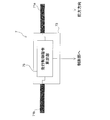
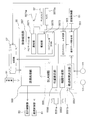
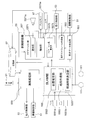
- the figure which shows the whole structure of an example of an autonomous traveling apparatus The figure which shows an example of a structure of a driving route teaching part. The figure which shows the structure of a setting part. The figure which shows the whole structure of a control part. The figure which shows the detailed structure of a traveling control part. The figure which shows the detailed structure of a control supervision part. The figure which shows an example of the coordinate system used with an autonomous running apparatus. The figure which shows an example of a definition of a 1st area
- the autonomous traveling device 100 is a cleaning machine that autonomously reproduces the taught cleaning condition and traveling route.
- “Teached cleaning condition” refers to a cleaning condition (cleaning condition) executed by a manual operation by an operator when the autonomous mobile device 100 is in a state in which it can be manually operated.
- the “taught travel route” refers to a route traveled by the autonomous travel device 100 by a manual operation (moving operation) by an operator.
- the autonomous traveling device 100 includes a traveling unit 1.
- the traveling unit 1 is a device that causes the autonomous traveling device 100 to travel.
- the traveling unit 1 has a main body B that constitutes a main body of the autonomous traveling device 100.
- the traveling unit 1 includes a traveling motor 11 and a main wheel 13 that is attached to the output rotation shaft of the traveling motor 11 and rotates according to the rotation of the traveling motor 11 at the left and right ends of the bottom of the main body B, respectively.
- the traveling unit 1 may have auxiliary wheels 15 that are rotatably attached to the left and right ends of the bottom of the main body B behind the main wheels 13, for example.
- the autonomous mobile device 100 can be made more stable.
- the auxiliary wheel 15 may be attached in front of the main wheel 13 in consideration of the position of the center of gravity of the autonomous traveling device 100 and the like.
- the autonomous traveling device 100 includes a cleaning unit 3.
- the cleaning unit 3 is a device that is provided at the bottom of the main body B and cleans the floor surface F in accordance with designated cleaning conditions.
- the cleaning unit 3 according to the present embodiment includes a cleaning liquid discharge port 31, a squeegee 33, and a cleaning member 35.
- the cleaning liquid discharge port 31 discharges the cleaning liquid (for example, water) supplied from the cleaning liquid supply tank 311 by the cleaning liquid supply pump 313 to the floor surface F on the front side of the main body B.
- the squeegee 33 is provided behind the bottom surface of the main body B, and collects the cleaning liquid remaining on the floor surface F.
- the cleaning member 35 is provided on the front side of the bottom surface of the main body B, and cleans the floor surface F by rotating on the floor surface F where the cleaning liquid exists by the rotation of the cleaning member rotating motor 351.
- the autonomous mobile device 100 can perform a cleaning operation of polishing the floor surface F with the cleaning member 35 using a cleaning liquid.
- the squeegee 33 may be provided with a suction port O2.
- the suction port O ⁇ b> 2 can suck the cleaning liquid or dust collected by the squeegee 33 and convey it to the recovery member 333 by putting the recovery member 333 in a negative pressure state by the suction motor 331.
- the autonomous mobile device 100 has a control unit 5.
- the control unit 5 is a computer system that includes a CPU, a storage device (RAM, ROM, hard disk drive, SSD, etc.), various interfaces, and the like.
- the control unit 5 performs various controls relating to the autonomous traveling device 100. The configuration of the control unit 5 will be described in detail later.
- the autonomous traveling device 100 includes a traveling route teaching unit 7.
- the travel route teaching unit 7 is a device that receives an operation of moving the travel unit 1 by an operator.
- the travel route teaching unit 7 is attached to the upper rear side of the main body B via the attachment member 8. Thereby, the operator can operate the travel route teaching unit 7 to move the travel unit 1. Details of the travel route teaching unit 7 of the present embodiment will be described later.
- the travel route teaching unit 7 may not be attached to the main body B.
- the travel route teaching unit 7 can be, for example, a controller such as a joystick. Thereby, the operator can remotely operate the autonomous mobile device 100.
- the autonomous traveling device 100 may be operable by both the traveling route teaching unit 7 and a controller that is not attached to the main body B.
- the autonomous traveling device 100 includes a setting unit 9.
- the setting unit 9 is an operation panel for performing various settings related to the autonomous mobile device 100, and is attached to the upper rear surface of the main body B.
- the setting unit 9 is provided in the vicinity of the travel route teaching unit 7. Thus, the operator can operate the setting unit 9 while operating the traveling unit 1 by operating the traveling route teaching unit 7.
- the setting unit 9 may not be attached to the main body B.
- the setting unit 9 can be a console capable of wireless communication such as a portable terminal. Thereby, the operator can set the autonomous traveling apparatus 100 remotely.
- the travel route teaching unit 7 and the setting unit 9 may be integrated. Thereby, it is possible to easily operate the traveling unit 1 and the setting unit at the same time.
- FIG. 2 is a diagram illustrating an example of the configuration of the travel route teaching unit.
- the travel route teaching unit 7 includes handles 71a and 71b.
- the handles 71a and 71b are attached to the left and right side surfaces of the housing 73, respectively.
- the handles 71a and 71b are used when the user operates the autonomous mobile device 100.
- the operator holding the handles 71a and 71b may apply either a force that pulls the autonomous traveling device 100 toward the operator or a force that pushes the autonomous traveling device 100 through the handles 71a and 71b. it can.
- the operator can adjust the traveling direction of the autonomous traveling device 100. For example, when a force for pulling the autonomous traveling device 100 is applied to the left handle 71a when viewed from the front direction of the autonomous traveling device 100, the autonomous traveling device 100 turns to the left.
- Handles 71a and 71b are rotatably attached to the casing 73.
- the handles 71 a and 71 b are connected to the control unit 5 via a travel control command calculation unit 75.
- the travel control command calculation unit 75 converts the rotation of the handles 71 a and 71 b into an electrical signal and outputs it to the control unit 5.
- the operator can operate the autonomous traveling device 100 (the traveling unit 1) by rotating the handles 71a and 71b.
- the operator may be able to switch between forward and backward movement of the autonomous traveling device 100 by adjusting the rotation direction of the handles 71a and 71b.
- the traveling speed of the autonomous traveling device 100 may be adjustable by adjusting the amount of rotation of the handles 71a and 71b.
- the traveling direction of the autonomous traveling device 100 may be changed by changing the amount of rotation of the handle 71a and the amount of rotation of the handle 71b.
- the handle 71a may be an input interface for instructing the traveling speed in the traveling direction
- the handle 71b may be an input interface for instructing the steering angle
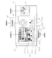
- FIG. 3 is a diagram illustrating a configuration of the setting unit.
- the setting unit 9 includes a switching unit 91.
- the switching unit 91 selects the operation mode of the autonomous traveling device 100 and outputs it to the control unit.
- the operation modes of the autonomous traveling device 100 include an autonomous cleaning mode (an example of an autonomous traveling mode) and a manual operation mode.
- the autonomous cleaning mode is an operation mode in which the autonomous traveling device 100 travels autonomously and cleans the floor surface F.
- the manual operation mode is an operation mode in which the autonomous traveling device 100 is in a state where it can be manually operated by an operator.
- the switching unit 91 can be configured by a changeover switch as shown in FIG. 3, for example.
- the autonomous cleaning mode can be selected, for example, by switching the switching unit 91 configured by a changeover switch to “automatic” shown in FIG.
- the manual operation mode can be selected, for example, by switching the switching unit 91 to “manual” shown in FIG.
- the setting unit 9 has a manual operation storage switch 92.
- the manual operation storage switch 92 is a switch for starting or ending storage of manual operation of the autonomous mobile device 100 by the operator. Specifically, when the manual operation storage switch 92 is pressed after the operation mode is set to the manual operation mode by the switching unit 91, the autonomous traveling device 100 determines the cleaning condition and the travel route executed by the manual operation of the operator.
- the manual operation teaching mode taught in (1) is started as a sub operation mode of the manual operation mode. On the other hand, when the manual operation storage switch 92 is switched during execution of the manual operation teaching mode, the manual operation teaching mode is stopped.
- the manual operation teaching mode can be started and stopped at an arbitrary timing by enabling the manual operation teaching mode to be started and stopped by the manual operation storage switch 92.
- a travel schedule 500 (an example of a route plan) desired by the operator can be created.
- the manual operation storage switch 92 for example, a push button switch as shown in FIG. 3 can be used. In this case, the manual operation storage switch 92 is switched by pressing the push button switch.
- the operation mode may be switched from the manual operation teaching mode to the manual operation mode. Thereby, even if the manual operation teaching mode is switched to the manual operation mode, the operator can manually operate the autonomous mobile device 100 continuously.
- the setting unit 9 has a cleaning condition teaching unit 93.
- the cleaning condition teaching unit 93 receives an input of the cleaning condition by the operator and outputs it to the cleaning control command calculation unit 94.
- the cleaning control command calculation unit 94 is a signal conversion circuit or a computer system that converts the cleaning condition received by the cleaning condition teaching unit 93 into a signal that can be decoded by the control unit 5 and outputs the signal to the control unit 5.
- the cleaning condition teaching unit 93 has a cleaning condition adjusting unit 931.
- the cleaning condition adjustment unit 931 includes a supply amount adjustment unit 931a that sets a supply amount S (an example of the discharge amount) of the cleaning liquid discharged from the cleaning liquid discharge port 31 as a teaching cleaning condition.
- the cleaning condition adjustment unit 931 includes a suction force adjustment unit 931b that is a push button for setting the suction force P by the suction port O2 as a teaching cleaning condition.
- the cleaning condition adjusting unit 931 includes a cleaning power adjusting unit 931c that sets the cleaning power W of the floor surface F by the cleaning member 35 as a teaching cleaning condition.
- the cleaning condition teaching unit 93 includes an operation switching unit 933.
- the operation switching unit 933 includes a supply switching unit 933a that is a push button for instructing start or stop of supply of the cleaning liquid from the cleaning liquid discharge port 31.
- the operation switching unit 933 includes a suction switching unit 933b that is a push button for instructing start or stop of suction through the suction port O2.
- the operation switching unit 933 includes a cleaning switching unit 933c that is a push button for instructing start or stop of cleaning of the floor surface F by the cleaning member 35.
- the cleaning condition teaching unit 93 has the above-described configuration, a cleaning operation of starting the suction of the cleaning liquid by the suction switching unit 933b after the supply of the cleaning liquid is stopped by the supply switching unit 933a and / or the cleaning liquid by the supply switching unit 933a. After the supply of water is stopped, the autonomous traveling device 100 can be caused to perform a cleaning operation such that the cleaning switching unit 933c starts cleaning the floor surface F after a lapse of time necessary for the cleaning liquid to adjust to the floor surface F. .
- the setting unit 9 has a setting operation unit 95.
- the setting operation unit 95 is configured by, for example, a push switch, and receives input of various settings related to the autonomous mobile device 100 and outputs the input to the control unit 5 via the setting conversion unit 96.
- the setting conversion unit 96 is a signal conversion circuit or a computer system that converts the input received by the setting operation unit 95 into a signal that can be decoded by the control unit 5.
- the setting unit 9 has a display 97.
- the display 97 displays various setting information related to the currently set autonomous traveling device 100.
- the display 97 is a display such as a liquid crystal display or an organic EL display.
- the display 97 uses, for example, the cleaning liquid supply amount S from the cleaning liquid discharge port 31, the cleaning force W of the floor surface F by the cleaning member 35, and / or the suction force P by the suction port O2 as the set cleaning conditions. indicate. Thereby, the operator can perform a cleaning operation while confirming the displayed cleaning conditions.
- the display 97 may further display the current operation mode (autonomous cleaning mode / manual operation mode / manual operation teaching mode), driving time, remaining battery level for driving the autonomous mobile device 100, and the like.
- the display 97 may display various setting procedures when performing various settings of the autonomous mobile device 100 using the setting operation unit 95. Thereby, the information regarding the autonomous mobile device 100 is visually provided to the user, and the user can operate the setting unit 9 based on the displayed information.
- the display 97 may be provided with a touch panel.
- the switching unit 91, the manual operation storage switch 92, the cleaning condition teaching unit 93, and / or the setting operation unit 95 may be realized by the touch panel.
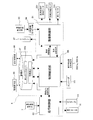
- FIG. 4 is a diagram illustrating the overall configuration of the control unit. All or some of the functional blocks of the control unit 5 described below may be realized by a program that can be executed by a computer system that configures the control unit 5. In this case, the program may be stored in the memory unit and / or the storage device. All or a part of each functional block of the control unit 5 may be realized as a custom IC such as SoC (System on Chip).
- SoC System on Chip
- the control unit 5 may be configured by one computer system or may be configured by a plurality of computer systems.
- functions realized by a plurality of functional blocks of the control unit 5 can be distributed and executed by a plurality of computer systems at an arbitrary ratio.
- the control unit 5 includes a cleaning control unit 51.
- the cleaning control unit 51 supplies power for controlling the rotation speed and output to the cleaning member rotation motor 351, the cleaning liquid supply pump 313, and the suction motor 331.
- the cleaning control unit 51 inputs a teaching cleaning condition from the cleaning condition teaching unit 93 via the cleaning control command calculation unit 94, and based on the teaching cleaning condition, The cleaning liquid supply pump 313 and the suction motor 331 are controlled.
- the cleaning control unit 51 inputs reproduction cleaning conditions (described later) from the control supervision unit 55, and controls the cleaning unit 3 based on the reproduction cleaning conditions.
- the control unit 5 includes a travel control unit 53.
- the travel control unit 53 controls the travel motor 11 based on the travel control command input from the travel route teaching unit 7 based on the travel control command based on the rotation amount and the rotation direction of the handles 71 a and 71 b or the control control unit 55.
- the traveling control unit 53 calculates the rotational speed of the traveling motor 11 based on a pulse signal output from the encoder 111 attached to the output rotation shaft of the traveling motor 11. Thereby, the traveling control unit 53 can control the traveling motor 11 while monitoring the rotational speed of the traveling motor 11 (that is, the rotational speed of the main wheel 13).
- the control unit 5 has a control supervision unit 55.
- the control supervision unit 55 supervises cleaning and traveling by the autonomous traveling device 100. Specifically, the control supervising unit 55 moves the position of the floor F on which the autonomous traveling device 100 moves based on the information acquired by the front detector 5551a, the rear detector 5551b, and / or the encoder 111. Position information indicating whether or not
- control supervision unit 55 When executing the manual operation teaching mode, the control supervision unit 55 receives the cleaning condition from the cleaning control unit 51 as the teaching cleaning condition, and creates the travel schedule 500 using the position information and the teaching cleaning condition.
- the control supervision unit 55 calculates the reproduction cleaning condition and the reproduction travel control command based on the data stored in the travel schedule 500, and the reproduction cleaning condition is sent to the cleaning control unit 51.
- a reproduction travel control command is output to travel control unit 53.
- the control unit 5 has a storage unit 57.
- the storage unit 57 is a part or all of the storage area of the storage device of the computer system that constitutes the control unit 5, and stores various information related to the autonomous mobile device 100. Specifically, the storage unit 57 stores the travel schedule 500 created by the control supervision unit 55 and various settings regarding the autonomous traveling device 100 input from the setting operation unit 95 and the setting conversion unit 96.
- the cleaning control unit 51, the travel control unit 53, and the control supervision unit 55 read various settings related to the autonomous travel device 100 and / or the travel schedule 500 stored in the storage unit 57 as necessary, and based on these. Various adjustments and controls can be performed.
- control unit 5 may include a data writing device (not shown) for storing information such as the travel schedule 500 stored in the storage unit 57 in another storage medium.
- control unit 5 may have a connection terminal to which a data writing device can be connected, such as a USB (Universal Serial Bus) port.
- a data writing device such as a USB (Universal Serial Bus) port.
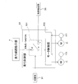
- FIG. 5 is a diagram illustrating a detailed configuration of the travel control unit.
- the travel control unit 53 includes a travel switching unit 531.
- the travel switching unit 531 has three terminals d, e, and f.
- the terminal d is connected to the travel route teaching unit 7
- the terminal e is connected to the motor control unit 533
- the terminal f is connected to the control control unit 55.
- the travel switching unit 531 selects either the connection between the terminal e and the terminal d or the connection between the terminal e and the terminal f based on the operation mode selected by the switching unit 91.
- the travel switching unit 531 connects the travel route teaching unit 7 to the motor control unit 533 by connecting the terminal e and the terminal d. .
- the travel switching unit 531 transmits a signal indicating the amount of rotation and / or the direction of rotation of the handles 71a and 71b of the travel route teaching unit 7 to the motor control unit 533 when the manual operation mode or the manual operation teaching mode is executed. it can.
- the travel switching unit 531 connects the control control unit 55 to the motor control unit 533 by connecting the terminal e and the terminal f. Thereby, the traveling switching unit 531 can transmit the reproduced traveling control command output from the control supervision unit 55 to the motor control unit 533 when the autonomous cleaning mode is executed.
- the motor control unit 533 calculates the target rotation speed of the travel motor 11 based on the input rotation amount / rotation direction of the handles 71a and 71b or the reproduction travel control command, and the travel motor is driven at the target rotation speed. Driving power for rotating the motor 11 is output to the traveling motor 11.
- the motor control unit 533 calculates the actual rotational speed of the traveling motor 11 based on the pulse signal from the encoder 111 and feeds it back to calculate the driving power to be output to the traveling motor 11. Therefore, the motor control unit 533 controls the traveling motor 11 using, for example, PI (Proportional Integral) control theory, PID (Proportional Integral Differential) control theory, or the like.
- the traveling motor 11 and the main wheel 13 are provided on the left and right ends of the bottom of the main body B, respectively.
- the motor control unit 533 determines the traveling direction of the autonomous traveling device 100 by independently controlling the rotational speed and rotational direction of the two left and right traveling motors 11.
- the motor control unit 533 may be one of the plurality of computer systems. That is, only the function of the motor control unit 533 may be realized by one computer system.
- the motor control unit 533 is a motor control device using, for example, PI control theory or PID control theory.
- the control supervision unit 55 includes a teaching data acquisition unit 551.
- the teaching data acquisition unit 551 acquires teaching position information and teaching cleaning conditions at the teaching data acquisition time when the manual operation teaching mode is executed. Specifically, the teaching data acquisition unit 551 inputs teaching data acquisition time and teaching position information from the SLAM unit 555 (described later), and inputs teaching cleaning conditions at the teaching data acquisition time from the cleaning control unit 51. As the acquisition time of the teaching data, for example, the system clock of the control unit 5 can be used.
- the teaching data acquisition unit 551 outputs the acquired teaching data acquisition time, teaching position information, and teaching cleaning conditions to the travel schedule creation unit 553.
- the control supervision unit 55 includes a travel schedule creation unit 553.
- the travel schedule creation unit 553 creates a travel schedule 500 by associating the teaching position information acquired from the teaching data acquisition unit 551, the teaching cleaning condition, and the teaching data acquisition time, and stores the traveling schedule 500 in the storage unit 57.
- the control supervision unit 55 has a SLAM unit 555.
- the SLAM unit 555 includes information regarding obstacles existing in front of the autonomous mobile device 100 acquired by the front detector 5551a (FIG. 1) provided in front of the main body B, and rear detection provided in the rear of the main body B.
- On the predetermined coordinates of the autonomous traveling device 100 based on the information about the obstacle existing behind the autonomous traveling device 100 acquired by the device 5551b (FIG. 1) and the rotation amount of the traveling motor 11 acquired by the encoder 111. Information on the position (position information) is estimated.
- the front detector 5551a and the rear detector 5551b are, for example, a laser range finder (LRF) having a detection range of 180 ° or more.
- LRF laser range finder
- the information acquired by the front detector 5551a and the rear detector 5551b may be two-dimensional information indicating the position of an obstacle on a predetermined plane, or the presence of an obstacle in the height direction. It may be three-dimensional information including information representing the position.
- the detection range (detection angle and / or detection distance) of the front detector 5551a may be wider than the detection range of the rear detector 5551b. Therefore, the information regarding the obstacle which exists in the front direction of the autonomous mobile device 100 and exists more widely can be acquired.
- the front detector 5551a and the rear detector 5551b may be a TOF (Time Of Flight) camera or the like.
- TOF Time Of Flight
- the control supervision unit 55 includes a navigation unit 557.
- the navigation unit 557 guides the traveling unit 1 (the autonomous traveling device 100) to the movement start position (stored in the traveling schedule 500) or the vicinity thereof.
- the navigation unit 557 moves the travel unit 1 to the movement start position and the travel unit 1 is estimated to have reached a relatively close position from the movement start position
- the navigation unit 557 It guides from the said position to a movement start position or its vicinity.
- a detailed configuration of the navigation unit 557 and a method for guiding the traveling unit 1 to the movement start position or the vicinity thereof will be described in detail later.
- the control supervision unit 55 has a cleaning reproduction unit 559.
- the cleaning reproduction unit 559 is based on the teaching data acquisition time, the teaching cleaning condition, and the teaching position information stored in the traveling schedule 500 when the autonomous cleaning mode is executed after the traveling unit 1 reaches or near the movement start position. Then, the reproduction cleaning condition and the reproduction travel control command at a predetermined elapsed time from the start of execution of the autonomous cleaning mode are calculated and output to the cleaning control unit 51 and the travel control unit 53, respectively.
- the SLAM unit 555 executes position (position information) estimation of the traveling unit 1 (autonomous traveling device 100) and creation of map information by a SLAM (Simultaneous Localization and Mapping) method.
- the SLAM unit 555 has a map creation unit 5553.
- the map creation unit 5553 uses the information on the front obstacle (for example, a wall) acquired by the front detector 5551a and the information on the rear obstacle acquired by the rear detector 5551b. Create information.
- the map information is used when the position estimation unit 5555 estimates position information. As map information, there are a local map and a global map.
- the local map is map information related to obstacles (existing positions) around the traveling unit 1.
- the local map is created by coordinate-converting the information about the front obstacle acquired by the front detector 5551a and the information about the rear obstacle acquired by the rear detector 5551b as necessary.
- the global map is map information related to an obstacle (existing position) present in an environment (moving environment) in which the traveling unit 1 moves.
- the global map is generated based on the local map acquired when the manual operation teaching mode is executed. Therefore, the local map acquired at the time of executing the manual operation teaching mode is stored in the storage unit 57 in association with the time (for example, the teaching data acquisition time) when it is acquired.
- the local map may be stored in the storage unit 57 in association with the estimated position of the traveling unit 1 when the local map is acquired.
- the map creation unit 5553 of this embodiment arranges a local map associated with a certain elapsed time and a local map associated with a time in the vicinity of the certain elapsed time at the position of the traveling unit 1 at each elapsed time. By placing the center of the local map at the position of the traveling unit 1 at the corresponding elapsed time, map information representing a part of the moving environment (for example, a range necessary for position estimation) Generate as a map. Also, the map creation unit 5553 deletes a part of the global map generated in the past that is no longer necessary for position estimation.
- the “circular route problem” (part of the global map generated in the initial stage and part of the global map generated in the final stage match. If the problem of disappearing does not occur, map information representing the entire mobile environment may be generated as a global map.
- the global map may be created using dedicated software, CAD, or the like and stored in the storage unit 57.
- the global map created by the software or the like is converted into data that can be interpreted by the control unit 5 of the traveling unit 1.
- the SLAM unit 555 includes a position estimation unit 5555.
- the position estimation unit 5555 is based on the global map generated by the map creation unit 5553, the local map, and the rotation amount of the travel motor 11, and the location of the travel unit 1 on a predetermined coordinate and the travel unit at the position. Position information related to one posture is estimated.
- the position information is estimated as follows.
- a position where the traveling unit 1 moves from an (estimated) position at a predetermined time ( denoted as time tk) and arrives at the next time ( denoted as time tk + 1 ) is determined.
- the position estimation unit 5555 the rotation amount of the main wheel 13 between the number of pulses output from the encoder 111 during the period from the time t k until the time t k + 1, from the time t k until the time t k + 1
- the travel distance and the posture change of the traveling unit 1 due to the rotation of the main wheel 13 are estimated based on the rotation amount (dead reckoning).
- the position estimation unit 5555 corresponds to a posterior probability at time t k (corresponding to a probability distribution representing a relationship between the position of the traveling unit 1 and the probability that the traveling unit 1 exists at the position at time t k ). Is moved by the moving distance and the posture change of the traveling unit 1 due to the rotation of the main wheel 13, and the prior probability at the time t k + 1 is calculated.
- the position estimation unit 5555 expands the width (standard deviation) of the probability distribution of the posterior probability after the movement by the movement distance and the posture change due to the rotation of the main wheel 13, and the time t k + 1. It is good also as prior probability in. Thereby, the prior probability considering the slip between the main wheel 13 and the floor surface F can be calculated.
- the position estimating unit 5555 obtains a local map and the global map from the mapping unit 5553 at time t k + 1, and map matching and a local map and a global map at time t k + 1, time t k + estimating the position information of the traveling unit 1 in one.
- local maps at time t k + 1 are arranged at several positions in the vicinity of the estimated position calculated based on the rotation amount of the main wheel 13, and the local map Is rotated by an angle corresponding to the posture change that can be taken around its center, and map matching is performed.
- the position estimation unit 5555 is based on the result of the map matching, and the likelihood (corresponding to the relationship between the position where the local map information is arranged and the degree of coincidence between the global map and the local map information at the position) Is calculated.
- the position estimation unit 5555 by multiplying the prior probability of the likelihood and the time t k + 1, to calculate the posterior probability at time t k + 1.
- the position estimation unit 5555 has a position and orientation at which the posterior probability at the time t k + 1 is the maximum value, that is, a position where the possibility that the traveling unit 1 is most likely to exist, and the traveling unit 1 at the position. Is estimated as the position (estimated position) of the traveling unit 1 and the position (estimated position) at the position t k + 1 at time t k + 1 .
- the posterior probability at time t k + 1 is used as the prior probability in the next position estimation.
- the position estimation unit 5555 performs position estimation using the movement distance based on the rotation amount of the main wheel 13 and the map information obtained using the front detector 5551a and the rear detector 5551b.
- an error included in the movement distance based on the rotation amount of the main wheel 13 mainly due to slippage between the main wheel 13 and the floor surface F
- an error included in the map information mainly
- the position estimation can be performed with a small amount of compensation in a complementary manner (due to noise components included in the information acquired by the front detector 5551a and the rear detector 5551b).
- the SLAM unit 555 includes an elapsed time determination unit 5557.
- the elapsed time determination unit 5557 determines the teaching data acquisition time and the elapsed time from the start of execution of the autonomous cleaning mode. In the present embodiment, the elapsed time determination unit 5557 determines the teaching data acquisition time by using a clock function such as a microcomputer system constituting the control unit 5, for example.
- the elapsed time from the start of execution of the autonomous cleaning mode is determined based on the position information estimated by the position estimation unit 5555. Specifically, for example, the teaching data acquisition time associated with the position information closest to the position information of the traveling unit 1 estimated by the position estimating unit 5555 among the position information stored in the traveling schedule 500 is set. And elapsed time.
- the elapsed time may be calculated by extracting two pieces of position information close to the position information estimated by the position estimation unit 5555 from the travel schedule 500 and linearly interpolating the two position information. Good. Thereby, a more accurate elapsed time can be calculated.
- the autonomous mobile device 100 By determining the elapsed time from the start of execution of the autonomous cleaning mode based on the position information estimated by the position estimation unit 5555, the autonomous mobile device 100 is instructed to teach teaching cleaning conditions when executing the autonomous cleaning mode. Cleaning work can be reproduced autonomously while accurately grasping the timing and place of execution. For example, at the time of execution of the autonomous cleaning mode, when the autonomous traveling device 100 decreases or stops moving that is not indicated in the traveling schedule 500 for the purpose of avoiding an obstacle, the cleaning work proceeds with time. Therefore, it is possible to avoid that the cleaning work that is not originally performed at the current position is autonomously performed.
- FIG. 6 is a diagram illustrating a detailed configuration of the navigation unit.
- the navigation unit 557 includes a notification unit 5571.
- the estimated position of the traveling unit 1 is in the first region A1
- the estimated posture of the traveling unit 1 is the first. If it is within one angle range ⁇ 1 , this is notified by, for example, making a sound through the speaker 5571a.
- the first area A1 is defined as an area that is regarded as a position relatively close to the movement start position P 0 in the navigation unit 557.
- the first region A1 is defined as a region including the movement start position P 0 and having a predetermined area. Further, the first area A1 is defined as an area for determining that the navigation unit 557 starts guiding the traveling unit 1 if the traveling unit 1 exists in the first region A1.
- the first angle range ⁇ 1 is defined as an angle range including the attitude of the traveling unit 1 at the movement start position P 0 (hereinafter referred to as a movement start attitude). That is, the first angle range ⁇ 1 is an angle range in which the posture of the traveling unit 1 is considered to be relatively close to the movement start posture if the posture of the traveling unit 1 is within this angle range.
- the first angle range ⁇ 1 is defined as an angle range for determining that the navigation unit 557 starts guiding the traveling unit 1 when the traveling unit 1 is in the first angle range ⁇ 1 .
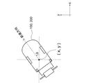
- the first area A1 and the first angle range ⁇ 1 of the present embodiment are defined as follows in an xy coordinate system (an example of predetermined coordinates) as shown in FIG. 7, for example.
- the xy coordinate system shown in FIG. 7 defines the x-axis in the horizontal direction of FIG. 7 and the y-axis in the vertical direction perpendicular thereto.
- An angle (posture ⁇ ) that increases counterclockwise from the x axis is defined with an angle parallel to the x axis being zero.
- an angle formed by the x-axis and the front-rear direction of the autonomous traveling device 100 (moving direction when going straight) is defined as the “posture” of the autonomous traveling device 100.
- FIG. 7 is an example of a coordinate system used in the autonomous mobile device.
- the first region A1 can be defined as a region within a circle having a radius R 1 with the movement start position P 0 as the center.
- the “predetermined area” of the first region A1 is ⁇ R 1 2 .
- the first angle range theta 1 is defined as the range of orientation theta of running portion 1 when the inequality of ⁇ 0 - ⁇ 1/2 ⁇ ⁇ ⁇ ⁇ 0 + ⁇ 1/2 is satisfied.
- FIG. 8 is a diagram illustrating an example of definitions of the first region, the first angle range, the second region, and the second angle range.
- the notification unit 5571 indicates that the current estimated position of the traveling unit 1 is in the position (in the region) where the navigation unit 557 starts guidance of the traveling unit 1. Can notify the surroundings.
- the first area A1 does not include the movement start position P 0 and / or the second area A2 described later, but is defined as an area that is considered to be a relatively close position from the movement start position P 0. May be.
- the first area A1 may be defined in front of the second area A2 without being forcibly included.
- navigation is performed navigation from the back of the movement start position P 0 and / or the second region A2 may fail. Accordingly, when there are many obstacles in front of the movement start position P 0 and / or the second area A2, navigation is started from the first area A1 defined in front of the second area A2 and not including the second area A2. , Navigation failure can be suppressed.
- the first angle range theta 1 is, although not include a second angle range theta 2, may be defined as an angle range in the vicinity of the second angle range theta 2.
- the navigation unit 557 includes a navigation amount calculation unit 5573.
- the navigation amount calculating unit 5573 guides the traveling unit 1 in the second area A2 and the posture in the second area A2 is the second. An operation amount of the traveling unit 1 for guiding the traveling unit 1 to be within the angle range ⁇ 2 is calculated.
- the second region A2 is defined as a region within a circle having a radius R 2 (R 2 ⁇ R 1 ) centered on the movement start position P 0 , for example.
- the second region A2 is included in the first region A1, and can be defined as a region including the movement start position P 0.
- the second angle range theta 2 is, for example, ⁇ 0 - ⁇ 2/2 ⁇ ⁇ ⁇ ⁇ 0 + ⁇ 2/2 ( ⁇ 2 ⁇ 1) and of the running portion 1 of the orientation theta when inequality holds for Defined as a range.
- the second angle range ⁇ 2 can be defined as an angle range that is included in the first angle range ⁇ 1 and includes the movement start posture ⁇ 0 .
- Running portion 1 is present in the second region A2 above and, when the posture ⁇ is running portion 1 is determined that the angle of the second angular range ⁇ 2, the control unit 5, the travel It is determined that the part 1 is present at or near the movement start position P 0 and the attitude ⁇ of the traveling part 1 is the movement start attitude or an angle near the movement start position P 0 , and the autonomous traveling device 100 is autonomous The operation can be started.
- the first area A1, the first angle range ⁇ 1 , the second area A2, and the second angle range ⁇ 2 are mathematical expressions (expressions representing the areas) in the xy coordinate system that define these areas and angle ranges. Alternatively, it is defined as an inequality, and the mathematical expression or inequality is stored in the storage unit 57.
- first area A1, the first angle range ⁇ 1 , the second area A2, and the second angle range ⁇ 2 are stored as coordinate values and angles of the boundary points of these areas and angle ranges. 57 may be stored.
- the estimated position of the running portion 1 is in the first area A1, and, when the estimated position of the running portion 1 is in the first angular range ⁇ 1, the travel unit 1
- the distance between the current estimated position and the movement start position P 0 stored in the travel schedule 500 is calculated as the travel distance to which the travel unit 1 should be guided.
- the navigation amount calculation unit 5573 calculates the difference between the current estimated posture of the traveling unit 1 and the movement start posture ⁇ 0 stored in the traveling schedule 500 as the direction in which the traveling unit 1 should be guided.
- the navigation unit 557 has a notification unit 5575.
- Notification unit 5575 induces travel unit 1 in the second region A2, and the operation of the attitude ⁇ in the second region A2 induces running portion 1 so that the second angle range ⁇ 2, the operator To inform.
- the notification unit 5575 outputs the movement distance calculated by the navigation amount calculation unit 5573 to guide the traveling unit 1 and the direction to guide the traveling unit 1 through the speaker 5571a. To inform.
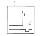
- the notification unit 5575 may visually display the movement distance and direction to which the traveling unit 1 calculated by the navigation amount calculation unit 5573 should be guided. Specifically, for example, as illustrated in FIG. 9, the notification unit 5575 displays a camera image representing an environment (front) of the traveling unit 1 acquired by a camera 5575a provided in front of the main body B. displays 97, directed onto the camera image, the driving unit 1 induced in the second region A2, and the running portion 1 so that orientation ⁇ in the second region A2 is a second angular range ⁇ within 2 You may display the operation for doing.
- FIG. 9 is a diagram illustrating an example in which an operation for guiding the traveling unit is displayed on the camera image.
- reporting part 5575 is a map (for example, movement) comprised by the information regarding the obstacle which exists in the circumference
- a global map stored in the storage unit 57 as representing the environment around the start position) is displayed on the display 97, the traveling unit 1 is guided into the second area A2 on the map, and the second area orientation ⁇ in the A2 may display an operation for inducing running portion 1 so that the second angle range ⁇ 2.
- the direction of the apex of the triangle representing the traveling unit 1 is the direction in which the traveling unit 1 should be guided.
- FIG. 10 is a diagram illustrating an example in which an operation for guiding a traveling unit is displayed on a map.
- the notification unit 5575 may represent the movement start position and the movement start posture with a triangle representing the traveling unit 1 on the map displayed on the display 97.
- the direction in which the apex of the triangle faces is the movement start posture.
- the center position of the map displayed on the display 97 may be the current estimated position of the traveling unit 1.
- the notification unit 5575 may display information representing the environment around the movement start position other than the map created by the map creation unit 5553 on the display 97. For example, a map created based on information obtained with a 3D-TOF camera, a map created based on information obtained with an infrared sensor, and created based on information obtained with an ultrasonic sensor Map, etc. can be displayed.
- the visual information (camera image, global map, etc.) displayed on the notification unit 5575 is when the autonomous traveling device 100 is installed (for example, when traveling for the first time or traveling environment). May be acquired in advance and stored in the storage unit 57 or the like. In this case, position information (coordinate values) or the like may be associated with the visual information acquired in advance.
- the notification unit 5575 reads visual information corresponding to the current position of the traveling unit 1 and superimposes information necessary for navigation on the visual information and displays the information on the display 97.
- the notification unit 5575 may display both visual information acquired in advance during installation and the visual information acquired during traveling of the traveling unit 1 on the display 97. Good.
- the notification unit 5575 displays the global map acquired during traveling and the camera image acquired in advance on the display 97 (overlapping or displaying in a divided individual area), and any information Information necessary for navigation may be superimposed and displayed on the top.
- the operator of the autonomous traveling device 100 guides the traveling unit 1 in the second area A2, and the second area orientation ⁇ in the A2 is an operation for inducing traveling portion so that the second angle range ⁇ 2, can be visually confirmed.
- the operator according to visually confirm the operation, the travel unit 1 is easily induced by the second region A2, and the orientation ⁇ in the second region A2 and the second angle range ⁇ within 2
- the traveling unit 1 can be guided more easily.
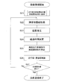
- FIG. 11 is a flowchart showing the basic operation of the autonomous mobile device.
- the control unit 5 confirms the state of the switching unit 91 (step S1).
- switching unit 91 has selected “automatic” (in the case of “autonomous cleaning mode” in step S 1)
- autonomous cleaning mode is executed (step S 2) and autonomous according to travel schedule 500 stored in storage unit 57.
- the traveling device 100 autonomously performs a cleaning operation.
- the control unit 5 determines that the operation mode to be executed is the manual operation mode.
- the control unit 5 shifts the operation mode to the manual operation teaching mode (step S4). .
- the cleaning work by the operator after the timing when the manual operation storage switch 92 is pressed is stored as the travel schedule 500.
- step S3 when the manual operation storage switch 92 is not pressed (in the case of “No” in step S3), execution of the manual operation mode in which the cleaning operation of the autonomous mobile device 100 by the operation of the operator is not stored is maintained (step S5) ).
- step S4 the control unit 5 monitors whether or not the manual operation storage switch 92 has been pressed.
- the operation mode is switched to the manual operation mode at that timing, and the cleaning work after that timing is not stored in the travel schedule 500. That is, by pressing the manual operation storage switch 92 during execution of the manual operation teaching mode, the operator can stop the storage (teaching) at an arbitrary timing during the cleaning operation.
- the autonomous traveling device 100 has the autonomous cleaning mode, the manual operation mode, the operation mode selection in the switching unit 91, and whether or not the manual operation storage switch 92 is pressed.
- the manual operation teaching mode can be executed.
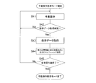
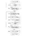
- FIG. 12 is a flowchart showing the operation in the manual operation teaching mode.
- the manual operation of the autonomous mobile device 100 is started after the manual operation storage switch 92 is pressed, or the manual operation storage switch 92 is pressed during the manual operation (step S41), and the manual operation is taught.
- creation of the travel schedule 500 is started.
- the teaching data acquisition unit 551 has the cleaning liquid output to the cleaning liquid supply pump 313 by the cleaning control unit 51 at that timing.
- the supply amount S, the suction force P output to the suction motor 331, and the cleaning force W output to the cleaning member rotation motor 351 are input as teaching cleaning conditions at an elapsed time of zero.
- the position estimation unit 5555 is instructed to estimate the position information of the traveling unit 1 at the elapsed time 0, and the estimated position information is input as teaching position information.
- the estimated position and estimated posture at the elapsed time 0 are a movement start position P 0 (coordinate values (x 0 , y 0 )) and a movement start posture ⁇ 0 , respectively.
- the travel schedule creation unit 553 inputs the teaching position information and the teaching cleaning condition at the elapsed time 0 from the teaching data acquisition unit 551 and stores the teaching position information and the teaching cleaning condition in the storage unit 57 in association with the elapsed time 0.
- the travel schedule 500 is used.
- the teaching data acquisition unit 551 monitors the elapsed time determined by the elapsed time determination unit 5557, and if the elapsed time is the teaching data acquisition time (in the case of “Yes” in step S42), the position Position information at the teaching data acquisition time is input from the estimation unit 5555 as teaching position information, and a cleaning condition at the teaching data acquisition time is input from the cleaning control unit 51 as teaching cleaning conditions (step S43). Thereby, teaching position information and teaching cleaning conditions can be acquired every teaching data acquisition time.
- the teaching data acquisition time can be set at a predetermined time (for example, 500 ms) after the manual operation storage switch 92 is pressed.
- the travel schedule creation unit 553 stores the teaching position information and the teaching cleaning condition acquired by the teaching data acquisition unit 551 in the traveling schedule 500 in association with the acquired teaching data acquisition time (step S44). By repeating the above steps S41 to S44 until the cleaning operation by the operator is completed (until “Yes” in step S45), teaching position information and teaching from the start to the end of the cleaning operation by the operator The cleaning conditions can be stored as the travel schedule 500.
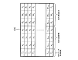
- FIG. 13 is a diagram illustrating an example of a travel schedule.
- T 0 , T 1 ,... T n are teaching data acquisition times.
- the teaching data acquisition time T 0 is set to 0.
- (X n , y n , ⁇ n ) are teaching position information at the corresponding teaching data acquisition time.
- (X n , y n ) are position information (coordinates) of the autonomous mobile device 100 on the xy coordinates at the corresponding teaching data acquisition time.
- ⁇ 0 , ⁇ 1 ,... ⁇ n are postures of the autonomous traveling device 100 at the corresponding teaching data acquisition time.
- S 0 , S 1 ,... S n are supply amounts of the cleaning liquid at the corresponding teaching data acquisition time.
- W 0 , W 1 ,... W n are the cleaning power of the floor surface F at the corresponding teaching data acquisition time.
- P 0 , P 1 ,... P n are suction forces of the suction port O2 at the corresponding teaching data acquisition time.
- FIG. 14 is a flowchart showing the operation of the autonomous mobile device when the autonomous cleaning mode is executed.
- the navigation unit 557 guides the traveling unit 1 to the movement start position and the movement start posture stored in the traveling schedule 500 or in the vicinity thereof.
- the operation is started (step S21).
- the navigation operation executed in step S21 will be described in detail later.
- the autonomous traveling device 100 autonomously travels and cleans the floor F according to the traveling schedule 500. Start. Specifically, the autonomous cleaning mode is executed as follows.
- the SLAM unit 555 acquires information on the front obstacle and information on the rear obstacle from the front detector 5551a and the rear detector 5551b (step S22).
- the position estimation unit 5555 is based on the rotation amount of the travel motor 11 measured by the encoder 111, the global map, and the local map obtained based on the information acquired in step S21. Is estimated on the xy coordinates (step S23). For example, the position of the autonomous driving apparatus 100, on the x-y coordinate, and (x m ', y m' , ⁇ m ') is estimated to be.
- the elapsed time determination unit 5557 determines the elapsed time t m from the start of execution of the autonomous cleaning mode (step S24), and the cleaning reproduction unit 559 reproduces the traveling control at the elapsed time t m .
- the command and the reproduction cleaning condition are calculated as follows (step S25).
- the cleaning reproduction unit 559 reads the position information (x L + 1 , y L + 1 , ⁇ L + 1 ) associated with the next teaching data acquisition time T L + 1 from the travel schedule 500, and the elapsed time
- the reproduction travel control command at the time t m is determined based on the difference between the estimated position information and the target position information (x L + 1 ⁇ x m ′, y L + 1 ⁇ y m ′, ⁇ L + 1 ⁇ m Calculate based on ').
- the cleaning reproducing unit 559 the cleaning condition associated with teaching data acquisition time T L (S L, W L , P L) reads from the travel schedule 500, the cleaning conditions (S L, W L, P L) Is determined as a reproduction cleaning condition at the elapsed time t m .
- the cleaning reproduction unit 559 After calculating the reproduction travel control command and the reproduction cleaning condition, the cleaning reproduction unit 559 outputs the reproduction travel control command to the travel control unit 53, and outputs the reproduction cleaning condition to the cleaning control unit 51 (step S26).
- the traveling control unit 53 moves the traveling unit 1 autonomously according to the traveling schedule 500 by controlling the traveling motor 11 based on the received reproduced traveling control command.
- the cleaning control part 51 controls the cleaning part 3 autonomously according to the driving schedule 500 by controlling the cleaning part 3 based on the received reproduction cleaning conditions.
- the cleaning reproducing unit 559 After controlling the traveling unit 1 and the cleaning unit 3 based on the reproduced traveling control command and the reproduced cleaning condition, respectively, the cleaning reproducing unit 559 checks whether or not all the cleaning operations stored in the traveling schedule 500 have been executed (step S27). ). Whether or not all the cleaning operations stored in the travel schedule 500 have been completed can be confirmed, for example, by detecting an identifier at the end of the travel schedule 500 (for example, an identifier indicating “end of file”).
- step S27 As long as it is determined that all the cleaning operations stored in the travel schedule 500 have not been executed (“No” in step S27), the above steps S22 to S26 are repeatedly executed and stored in the travel schedule 500. When it is determined that all cleaning operations have been performed (in the case of “Yes” in step S27), the execution of the reproduction cleaning mode is terminated. Thereby, the autonomous mobile device 100 can faithfully reproduce the cleaning work stored in the travel schedule 500.
- the user is instructed to stop the reproduction cleaning mode. In some cases, the execution of the reproduction cleaning mode may be stopped.
- the cleaning reproduction unit 559 calculates the reproduction cleaning condition and the reproduction travel control command based on the travel schedule 500 created by the travel schedule creation unit 553, respectively.
- the autonomous traveling device 100 can autonomously execute a cleaning operation.
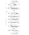
- FIG. 15 is a flowchart showing the navigation operation according to the first embodiment.
- the travel switching unit 531 of the travel control unit 53 connects the terminal e and the terminal d.
- navigation of the travel unit 1 is started from an arbitrary position (for example, a charging station for charging a battery provided in the autonomous travel device 100). Move to the first area A1. Further, the posture of the traveling unit 1 is set to an angle within the first angle range ⁇ 1 by manual operation (step S211).
- the traveling unit 1 by a manual operation by moving in the first region A1, while the attitude ⁇ of the running portion 1 and the angle of the first angle range ⁇ 1, the navigation unit 557, at predetermined time intervals, the position estimation unit From 5555, the current estimated position and estimated posture of the traveling unit 1 are acquired.
- the navigation unit 557 determines whether the current estimated position of the traveling unit 1 exists in the first area A1 and the current estimated posture is in the first angle range ⁇ 1 (step S212).
- the navigation unit 557 determines that the coordinate value (x, y) of the current estimated position in the xy coordinate system is (x ⁇ x 0 ) 2 + (y ⁇ y 0 ) 2 ⁇ R 1 2 meets inequality, and determines whether theta current estimated pose satisfy ⁇ 0 - ⁇ 1/2 ⁇ ⁇ ⁇ ⁇ 0 + ⁇ 1/2 inequality.
- the navigation unit 557 may instruct the position estimation unit 5555 to expand the estimated range of the estimated position and estimated posture while executing the above step S212. Specifically, for example, it may be instructed to expand the range of coordinates where the local map is arranged in map matching and expand the rotation angle range of the local map at each arrangement position of the local map.
- the operator determines the current position of the traveling unit 1. By grasping and manually operating, the traveling unit 1 can be moved into the first area A1, and the posture ⁇ of the traveling unit 1 can be set to an angle within the first angle range ⁇ 1 .
- the maximum speed at which the traveling unit 1 can travel may be reduced.
- the estimation range of the estimated position and the estimated posture is expanded, a larger amount of calculation is required for estimating the estimated position and the estimated posture. As a result, it takes time until the estimated position and the estimated posture are specifically calculated. Therefore, by reducing the maximum speed of the traveling unit 1 in such a case, it is possible to avoid the calculation of the estimated position and the estimated posture from catching up with the manual operation by the operator. As a result, it is possible to avoid a deviation between the estimated position and the estimated posture and the actual position and posture of the traveling unit 1.
- step S212 When it is determined as a result of manual operation of the traveling unit 1 by the operator that the estimated position of the traveling unit 1 exists in the first area A1 and the estimated posture ⁇ is within the first angle range ⁇ 1 (step S212).
- the notification unit 5571 emits a predetermined sound or voice from the speaker 5571a, for example, the traveling unit 1 exists in the first region A1 and the posture is within the first angle range ⁇ 1 . Then, it is notified that the navigation operation of the traveling unit 1 is possible (step S213).
- an operator who has manually operated the traveling unit 1 can confirm that the traveling unit 1 has been moved to a position and posture where navigation operation is possible.
- the navigation unit 557 After running portion 1 becomes navigable state, the navigation unit 557, a traveling unit 1 is moved in the second region A2, the posture of the traveling unit 1 for the angle of the second angular range ⁇ within 2 Start navigation.
- the navigation amount calculating unit 5573 is, requires a distance between the current estimated position of the running portion 1 and the movement start position P 0, in order to move the running portion 1 on the movement start position P 0 It is calculated as a navigation amount that represents a long moving distance. Further, the difference between the currently estimated position theta movement start position theta 0 of the traveling unit 1, it is calculated as a navigation quantity representing the posture variation required the posture of the traveling unit 1 to the movement start position theta 0 ( Step S214).
- the navigation amount calculation unit 5573 outputs the calculated navigation amount to the notification unit 5575 (step S215).
- the notification unit 5575 generates a sound signal for notifying the input navigation amount by sound, and outputs the sound signal to the speaker 5571a.
- the speaker 5571a emits, for example, “Please proceed ⁇ m in the direction of ⁇ ” with the navigation amount as voice.
- the notification unit 5575 when the notification unit 5575 displays the navigation amount on the display 97, the notification unit 5575 acquires a current camera image around the autonomous mobile device 100 by the camera 5575a.
- a camera image acquired in advance and stored in the storage unit 57 or the like is read out.
- the acquired or read camera image represents character information indicating a navigation amount such as “Please proceed ⁇ m in the ⁇ direction” and the direction in which the traveling unit 1 should be operated.
- An image signal may be generated by superimposing the arrow and output to the display 97. Thereby, as shown in FIG. 9, the navigation amount can be displayed on the camera image.
- the navigation amount calculation unit 5573 calculates the navigation amount, and the position estimation unit 5555 On the other hand, it may be instructed to reduce (return) the estimated range of the estimated position and estimated posture.
- the traveling route teaching unit 7 and the like Based on the notification from the notification unit 5575, the operator who has grasped the navigation amount for moving the traveling unit 1 to or near the movement start position P 0 and the movement start posture ⁇ 0, the traveling route teaching unit 7 and the like according to the navigation amount Operate manually.
- the control signal based on the manual operation is output to the motor control unit 533 via the travel switching unit 531, the travel control unit 53 moves toward the movement start position P 0 and the movement start posture ⁇ 0 or in the vicinity thereof.
- the traveling unit 1 is moved (step S216).
- the navigation unit 557 acquires the current estimated position and estimated posture of the traveling unit 1 from the position estimation unit 5555 at every predetermined time during the execution of the above steps S213 to S216.
- the navigation unit 557 determines whether the current estimated position of the traveling unit 1 exists in the second region A2 and the current estimated posture is in the second angle range ⁇ 2 (step S217). Specifically, for example, the navigation unit 557 determines that the coordinate value (x, y) of the current estimated position in the xy coordinate system is (x ⁇ x 0 ) 2 + (y ⁇ y 0 ) 2 ⁇ R 2 2. meets inequality, and determines whether theta current estimated pose satisfy ⁇ 0 - ⁇ 2/2 ⁇ ⁇ ⁇ ⁇ 0 + ⁇ 2/2 inequality.
- step S217 When it is determined that the current estimated position of the traveling unit 1 exists in the second area A2 and the current estimated posture is in the second angle range ⁇ 2 (in the case of “Yes” in step S217), Since the traveling unit 1 has arrived at or near the movement start position P 0 and the movement start posture ⁇ 0 , it is determined that the autonomous cleaning mode can be executed.
- the navigation unit 557 stops guiding the traveling unit 1 (step S218). Specifically, the navigation amount calculation unit 5573 stops the calculation and output of the navigation amount, and the notification unit 5575 stops the notification of the navigation amount. Thereby, the operator can grasp that the traveling unit 1 has been moved to the movement start position P 0 and the movement start posture ⁇ 0 or the vicinity thereof, and can stop the manual operation of the traveling unit 1. That is, the operator reliably allowed to reach the second area A2 of the travel unit 1, to ensure the attitude ⁇ of the traveling unit 1 can the angle of the second angular range ⁇ 2.
- the notification unit 5575 terminates the navigation because “the movement start position has been reached. You may be informed. Thus, the operator can more clearly grasp that the traveling unit 1 can be moved to the movement start position P 0 and the movement start posture ⁇ 0 or the vicinity thereof.
- Step S217 when it is not determined that the current estimated position of the traveling unit 1 exists in the second region A2 and the current estimated posture is in the second angle range ⁇ 2 (that is, Step S217).
- Step S217 for example, when the operator stops the traveling unit 1 and presses a button (not shown) provided in the setting unit 9, the calculation of the navigation amount is performed again. The amount of navigation is notified.
- the traveling unit Stop induction 1 when the operator stops the traveling unit 1 and presses a button (not shown) provided in the setting unit 9, the calculation of the navigation amount is performed again. The amount of navigation is notified.
- the traveling unit Stop induction 1 for example, when the operator stops the traveling unit 1 and presses a button (not shown) provided in the setting unit 9, the calculation of the navigation amount is performed again. The amount of navigation is notified.
- the traveling unit Stop induction 1 if the operator continues to operate the traveling unit 1, and it is determined that the position of the traveling unit 1 exists in the second region A2 and the posture is in the second angle range
- the traveling unit 1 when the traveling unit 1 is moved to the movement start position P 0 in order to execute the autonomous cleaning mode, the estimated position of the traveling unit 1 is within the first region A1, and When the estimated posture of the traveling unit 1 is within the first angle range ⁇ 1 , the navigation unit 557 guides the traveling unit 1 to a position in the second region A2, and the posture of the traveling unit 1 is the second. It induces running portion 1 so as to be angular range ⁇ 2. That is, the error between the current position of the traveling unit 1 and the movement start position P 0 is within a certain range, and the error between the current position of the traveling unit 1 and the movement start posture ⁇ 0 is within a certain range.
- the autonomous traveling device 100 can be reliably moved to the movement start position P 0 and the movement start posture ⁇ 0 or the vicinity thereof, and the autonomous cleaning device 100 can be reliably started in the autonomous cleaning mode. Further, the operator does not need to move the autonomous mobile device 100 to the movement start position P 0 and the movement start posture ⁇ 0 accurately based only on his / her own judgment by the above navigation operation. As a result, it is possible to reduce the operator's workload required until the autonomous traveling device 100 starts the autonomous traveling mode.
- the change in the posture of the unit 1 (the rotation operation of the traveling unit 1) can be reduced.
- the travel unit 1 is moved into the first region A1 by the operation of the operator, and the travel unit If the posture of 1 is an angle within the first angle range ⁇ 1 , the traveling unit 1 may autonomously move to the movement start position P 0 and the movement start posture ⁇ 0 or in the vicinity thereof.
- the navigation amount calculation unit 5573 calculates a navigation amount, calculates a navigation travel control command based on the navigation amount, and sends the navigation control command to the travel control unit 53.
- FIG. 16 is a diagram illustrating a configuration of a control control unit according to the second embodiment.
- FIG. 17 is a flowchart showing a navigation operation according to the second embodiment.
- the running portion 1 is moved in the first region A1, the posture of the running portion 1 and the angle of the first angle range ⁇ 1 (Steps S211 ′ to S212 ′).
- the travel unit 1 is present in the first region A1, when the posture of the running portion 1 is in the first angular range ⁇ 1, the notification unit 5571 that This may be notified by voice or the like. Thereby, it is possible to notify the operator and / or persons around the autonomous mobile device 100 that the autonomous navigation operation is started.
- the navigation amount calculation unit 5573 calculates the navigation amount of the traveling unit 1 in the same manner as in the first embodiment (step S213 ′).
- the navigation amount may be notified to the notification unit 5575 after the navigation amount is calculated.
- “traveling ⁇ m in the direction of ⁇ ” informs how the traveling unit 1 will move in the future. Thereby, the travel distance and the travel direction of the travel unit 1 can be notified to the operator of the autonomous travel device 100 and / or the surrounding persons.
- the travel switching unit 531 connects the terminal e and the terminal f.
- the navigation amount calculation unit 5573 Based on the calculated navigation amount, the navigation amount calculation unit 5573 outputs the output to the traveling control unit 53 in order to move the traveling unit 1 to the movement start position P 0 and change the posture of the traveling unit 1 to the movement start posture ⁇ 0.
- a navigation travel control command to be calculated is calculated.
- the navigation amount calculation unit 5573 first calculates a navigation travel control command for directing the travel unit 1 in the direction of the movement start position P 0 and outputs the navigation travel control command to the travel control unit 53 (step S214 ′). At this time, the navigation amount calculation unit 5573 first calculates the posture when the traveling unit 1 faces the direction of the movement start position P 0 . For example, assuming that the current estimated position of the traveling unit 1 is (x ′, y ′), the posture when the traveling unit 1 is directed toward the movement start position P 0 is tan ⁇ 1 ((( y 0 ⁇ y ′) / (x 0 ⁇ x ′)).
- the navigation amount calculation unit 5573 generates a navigation travel control command based on the difference between the current estimated posture ⁇ of the travel unit 1 and the angle tan ⁇ 1 ((y 0 ⁇ y ′) / (x 0 ⁇ x ′)). Is output to the travel control unit 53. Thereby, the traveling control unit 53 rotates the traveling unit 1 in the direction of the movement start position P 0 based on the navigation traveling control command.
- the navigation amount calculation unit 5573 calculates a navigation travel control command for moving the travel unit 1 straight from the current position to the movement start position P 0 and outputs the navigation travel control command to the travel control unit 53 (step S215 ′).
- This navigation travel control command can be calculated based on the distance between the current estimated position of the travel unit 1 and the movement start position P 0 .
- the travel control unit 53 that has received this navigation travel control command moves the travel unit 1 straight to the movement start position P 0 .
- the navigation amount calculation unit 5573 calculates a navigation travel control command for directing the travel unit 1 in the direction of the movement start posture ⁇ 0 at the current position, and outputs the navigation travel control command to the travel control unit 53 ( Step S216 ′).
- This navigation travel control command can be calculated based on the difference between the angle tan ⁇ 1 ((y 0 ⁇ y ′) / (x 0 ⁇ x ′)) calculated in step S214 ′ and the movement start posture ⁇ 0 .
- the travel control unit 53 that has received the navigation travel control command rotates the travel unit 1 until the posture of the travel unit 1 reaches the movement start posture ⁇ 0 .
- the navigation unit 557 determines that the estimated position of the traveling unit 1 exists in the second area A2 and the estimated posture of the traveling unit 1 It is determined whether ⁇ is within the second angle range ⁇ 2 (step S217 ′). If the estimated position of the traveling unit 1 exists in the second area A2 and the estimated posture ⁇ of the traveling unit 1 is within the second angle range ⁇ 2 (in the case of “Yes” in step S217 ′), The navigation unit 557 stops the guidance of the traveling unit 1 (step S218 ′) and ends the navigation operation.
- the estimated position of the traveling unit 1 does not exist in the second region A2 even if the above steps S213 ′ to S216 ′ are executed due to slippage between the floor surface F and the main wheel 13, for example.
- the autonomous cleaning mode can be executed. The traveling unit 1 is moved to the position and orientation, and the above steps S213 ′ to S216 ′ are executed again.
- Navigation amount calculating unit 5573 is, as described above, to induce the traveling unit 1 in the second region A2, and induce the traveling unit 1 so that the posture in the second region A2 is a second angular range ⁇ within 2
- the navigation travel control command is calculated and output to the travel control unit 53, so that the travel unit 1 is autonomously guided into the second area A2, and the attitude of the travel unit 1 in the second area A2 is autonomous. possible to the angle of the second angular range ⁇ within 2 to.
- the change in the posture of the unit 1 (the rotation operation of the traveling unit 1) can be reduced.
- the autonomous traveling device 100 may be a traveling device other than a cleaning machine that autonomously performs a cleaning operation.
- the autonomous traveling device 100 may be an advertising robot.
- the autonomous traveling device 100 may be configured only by a traveling unit (and a control unit that controls the traveling unit) for traveling autonomously.
- a robot (device) having a desired function can be configured by combining the autonomous traveling device and a robot system for exhibiting a desired function.
- the traveling schedule 500 does not store the cleaning condition. Or it replaces with cleaning conditions and the information regarding the control according to the use of the autonomous mobile device 100 may be memorize
- the first region A1 and / or the second region A2 may have a shape other than a circle (for example, a polygon such as a quadrangle).
- the shape of these regions can be appropriately determined in consideration of the moving environment, use conditions, and the like. Further, when the moving environment and / or use conditions of the autonomous mobile device 100 change, the shape and / or area of these regions once determined may be changed as appropriate.
- the first angular range ⁇ 1 and / or the second angular range ⁇ 2 are also changed as appropriate when the moving environment and / or usage conditions of the autonomous traveling device 100 change. May be.
- the navigation operation according to the first and second embodiments described above may be executed as long as the traveling unit 1 exists in the first region A1. That is, when starting the navigation operation, as long as the traveling unit 1 exists in the first region A1, the posture of the traveling unit 1 may be an arbitrary posture. As a result, the navigation operation can be started no matter what direction the first area A1 is reached.
- the position estimation unit 5555 may perform position estimation of the traveling unit 1 by position estimation by laser odometry using only information obtained from the front detector 5551a and the rear detector 5551b.
- a position estimation method by laser odometry for example, there is an ICP (Iterative Closest Point) method.
- the unit 5555 may estimate the position of the traveling unit 1 based only on the rotation amount of the traveling motor 11.
- the setting unit 9 may have a button for causing the notification unit 5575 to notify the navigation amount. For example, when the operator wishes to notify the navigation amount again, the operator can confirm the navigation amount again by pressing the button.
- the present invention can be widely applied to an autonomous traveling device that autonomously travels according to a route plan from a movement start position to a movement end position.
Landscapes
- Engineering & Computer Science (AREA)
- Aviation & Aerospace Engineering (AREA)
- Radar, Positioning & Navigation (AREA)
- Remote Sensing (AREA)
- Physics & Mathematics (AREA)
- General Physics & Mathematics (AREA)
- Automation & Control Theory (AREA)
- Mechanical Engineering (AREA)
- Electric Vacuum Cleaner (AREA)
- Control Of Position, Course, Altitude, Or Attitude Of Moving Bodies (AREA)
Abstract
La présente invention concerne un appareil à déplacement autonome destiné à effectuer un déplacement autonome, qui, grâce à l'invention, peut avancer de manière fiable vers une position à partir laquelle ledit appareil peut commencer à se déplacer de façon autonome. L'appareil à déplacement autonome 100 comprend : une unité de déplacement 1; une unité d'estimation de position 5555; une unité de navigation 557; et une unité de commande de déplacement 53. L'unité d'estimation de position 5555 estime la position et l'attitude de l'unité de déplacement 1. Dans le cas où la position estimée est située à l'intérieur d'une première zone A1, l'unité de navigation 557 guide l'unité de déplacement 1 vers une seconde zone A2 et guide l'unité de déplacement 1 de telle sorte que son attitude dans la seconde zone A2 est comprise dans une seconde plage angulaire Θ2. L'unité de commande de déplacement 53 commence son opération de commande afin d'amener l'unité de déplacement 1 à se déplacer de manière autonome lorsque l'unité de déplacement 1 a atteint l'intérieur de la seconde zone A2 et lorsque l'attitude de l'unité de déplacement 1 à l'intérieur de ladite seconde zone A2 est comprise dans la seconde plage angulaire Θ2.
Priority Applications (1)
| Application Number | Priority Date | Filing Date | Title |
|---|---|---|---|
| JP2018537110A JP6610797B2 (ja) | 2016-08-31 | 2017-08-16 | 自律走行装置 |
Applications Claiming Priority (2)
| Application Number | Priority Date | Filing Date | Title |
|---|---|---|---|
| JP2016169668 | 2016-08-31 | ||
| JP2016-169668 | 2016-08-31 |
Publications (1)
| Publication Number | Publication Date |
|---|---|
| WO2018043128A1 true WO2018043128A1 (fr) | 2018-03-08 |
Family
ID=61300558
Family Applications (3)
| Application Number | Title | Priority Date | Filing Date |
|---|---|---|---|
| PCT/JP2017/028440 Ceased WO2018043033A1 (fr) | 2016-08-31 | 2017-08-04 | Machine de nettoyage de sol à déplacement autonome |
| PCT/JP2017/029438 Ceased WO2018043128A1 (fr) | 2016-08-31 | 2017-08-16 | Appareil à déplacement autonome |
| PCT/JP2017/029788 Ceased WO2018043180A1 (fr) | 2016-08-31 | 2017-08-21 | Procédé de création d'itinéraire de déplacement, dispositif de déplacement autonome et programme |
Family Applications Before (1)
| Application Number | Title | Priority Date | Filing Date |
|---|---|---|---|
| PCT/JP2017/028440 Ceased WO2018043033A1 (fr) | 2016-08-31 | 2017-08-04 | Machine de nettoyage de sol à déplacement autonome |
Family Applications After (1)
| Application Number | Title | Priority Date | Filing Date |
|---|---|---|---|
| PCT/JP2017/029788 Ceased WO2018043180A1 (fr) | 2016-08-31 | 2017-08-21 | Procédé de création d'itinéraire de déplacement, dispositif de déplacement autonome et programme |
Country Status (5)
| Country | Link |
|---|---|
| US (1) | US10980387B2 (fr) |
| EP (1) | EP3508104B1 (fr) |
| JP (3) | JP6711405B2 (fr) |
| CN (1) | CN109640775B (fr) |
| WO (3) | WO2018043033A1 (fr) |
Cited By (3)
| Publication number | Priority date | Publication date | Assignee | Title |
|---|---|---|---|---|
| TWI716127B (zh) * | 2019-10-01 | 2021-01-11 | 東元電機股份有限公司 | 機器人及其路徑插值規劃命令產生系統 |
| CN112621739A (zh) * | 2019-10-08 | 2021-04-09 | 东元电机股份有限公司 | 机器人及其路径插值规划命令产生系统 |
| CN116197197A (zh) * | 2023-01-17 | 2023-06-02 | 中国石油大学(华东) | 一种冲洗排污协同处理的储油罐清洗方法 |
Families Citing this family (29)
| Publication number | Priority date | Publication date | Assignee | Title |
|---|---|---|---|---|
| EP3439522B1 (fr) * | 2016-04-08 | 2023-06-07 | A&K Robotics Inc. | Autolaveuse convertible entre un fonctionnement à commande manuelle et un fonctionnement autonome |
| JP7063738B2 (ja) * | 2018-06-14 | 2022-05-09 | 東芝ライフスタイル株式会社 | 自律走行式掃除機および掃除システム |
| JP7262076B2 (ja) | 2018-06-28 | 2023-04-21 | パナソニックIpマネジメント株式会社 | 移動ロボット、及び、制御方法 |
| KR20200069103A (ko) * | 2018-12-06 | 2020-06-16 | 삼성전자주식회사 | 로봇 청소기 및 로봇 청소기의 청소 경로 계획 방법 |
| JP7663313B2 (ja) * | 2019-03-20 | 2025-04-16 | 村田機械株式会社 | 自律走行台車、及び、制御方法 |
| JP7441067B2 (ja) * | 2019-03-22 | 2024-02-29 | 株式会社安藤・間 | 移動式ひび割れ検出装置、及びひび割れ検出方法 |
| KR102275300B1 (ko) | 2019-07-05 | 2021-07-08 | 엘지전자 주식회사 | 이동 로봇 및 그 제어방법 |
| KR102224637B1 (ko) | 2019-07-05 | 2021-03-08 | 엘지전자 주식회사 | 이동 로봇 및 그 제어방법 |
| KR102361130B1 (ko) | 2019-07-11 | 2022-02-09 | 엘지전자 주식회사 | 이동 로봇 및 그 제어방법 |
| KR102297496B1 (ko) | 2019-07-11 | 2021-09-02 | 엘지전자 주식회사 | 인공지능을 이용한 이동 로봇 및 이동 로봇의 제어방법 |
| KR102302575B1 (ko) | 2019-07-16 | 2021-09-14 | 엘지전자 주식회사 | 이동 로봇 및 그 제어방법 |
| CN110568848B (zh) * | 2019-09-10 | 2022-09-23 | 东风商用车有限公司 | 清扫车的示教自动驾驶作业系统 |
| WO2021106331A1 (fr) | 2019-11-25 | 2021-06-03 | 村田機械株式会社 | Chariot mobile autonome, procédé de commande et programme |
| JP7047830B2 (ja) * | 2019-12-05 | 2022-04-05 | オムロン株式会社 | 自律走行システム、自律走行方法、及び自律走行プログラム |
| JP7552347B2 (ja) * | 2020-03-05 | 2024-09-18 | 村田機械株式会社 | 自律走行台車 |
| KR20210123932A (ko) * | 2020-04-06 | 2021-10-14 | 엘지전자 주식회사 | 로봇청소기 및 그 제어방법 |
| CN115053027A (zh) * | 2020-07-22 | 2022-09-13 | 松下知识产权经营株式会社 | 衣物处理装置 |
| JP7574568B2 (ja) | 2020-08-17 | 2024-10-29 | 村田機械株式会社 | 自律走行経路計画方法 |
| NL2026276B1 (en) * | 2020-08-17 | 2022-04-14 | Wensch Holding B V | Self-propelled cleaning device |
| JP2022037518A (ja) * | 2020-08-25 | 2022-03-09 | 日本信号株式会社 | 床掃除機 |
| JP7484669B2 (ja) * | 2020-11-04 | 2024-05-16 | 村田機械株式会社 | 自律走行体の走行教示記憶方法、自律走行体、記録媒体 |
| JP7615618B2 (ja) | 2020-11-04 | 2025-01-17 | 村田機械株式会社 | 自律走行経路計画方法 |
| JP7577518B2 (ja) * | 2020-11-25 | 2024-11-05 | 日本信号株式会社 | 作業経路決定装置 |
| US20220233046A1 (en) * | 2021-01-22 | 2022-07-28 | John Mortensen | Robotic mop |
| JP7672046B2 (ja) * | 2021-06-15 | 2025-05-07 | パナソニックIpマネジメント株式会社 | 走行用地図作成装置、自走式ロボットシステム、走行用地図作成方法、及び、プログラム |
| CN113616117B (zh) * | 2021-08-13 | 2022-08-16 | 珠海格力电器股份有限公司 | 清扫区域确定方法、装置、设备及存储介质 |
| JP7777792B2 (ja) * | 2021-11-18 | 2025-12-01 | パナソニックIpマネジメント株式会社 | 走行用地図作成装置及び自律走行型ロボット |
| JP7821961B2 (ja) * | 2022-02-21 | 2026-03-02 | パナソニックIpマネジメント株式会社 | 走行用地図作成装置、自律走行型ロボット、走行用地図作成方法、及び、プログラム |
| JP2024131730A (ja) * | 2023-03-16 | 2024-09-30 | 株式会社ナチュラルスタイル | 自走式作業機の経路生成装置 |
Citations (1)
| Publication number | Priority date | Publication date | Assignee | Title |
|---|---|---|---|---|
| JP2007004434A (ja) * | 2005-06-23 | 2007-01-11 | Yoichiro Sawa | 移動ロボットシステム |
Family Cites Families (13)
| Publication number | Priority date | Publication date | Assignee | Title |
|---|---|---|---|---|
| JP3346513B2 (ja) * | 1994-07-01 | 2002-11-18 | ミノルタ株式会社 | マップ記憶方法及びそのマップを使用する経路作成方法 |
| JPH08326025A (ja) * | 1995-05-31 | 1996-12-10 | Tokico Ltd | 清掃ロボット |
| GB0126492D0 (en) * | 2001-11-03 | 2002-01-02 | Dyson Ltd | An autonomous machine |
| JP2005078415A (ja) * | 2003-09-01 | 2005-03-24 | Fuji Heavy Ind Ltd | 走行経路生成方法、走行経路生成装置およびコンピュータプログラム |
| JP4264009B2 (ja) * | 2004-01-23 | 2009-05-13 | シャープ株式会社 | 自走式掃除機 |
| KR20090077547A (ko) * | 2008-01-11 | 2009-07-15 | 삼성전자주식회사 | 이동 로봇의 경로 계획 방법 및 장치 |
| DE102009052629A1 (de) * | 2009-11-10 | 2011-05-12 | Vorwerk & Co. Interholding Gmbh | Verfahren zur Steuerung eines Roboters |
| JP5759810B2 (ja) * | 2011-07-08 | 2015-08-05 | アマノ株式会社 | 床面洗浄機 |
| JP6227948B2 (ja) * | 2013-09-18 | 2017-11-08 | 村田機械株式会社 | 自律走行式床洗浄機、清掃スケジュールのデータ構造、記憶媒体、清掃スケジュールの生成方法、及びプログラム |
| US20150196182A1 (en) * | 2014-01-13 | 2015-07-16 | Tennant Company | Water Recycling System for Mobile Surface Cleaners |
| JP5676039B1 (ja) * | 2014-05-28 | 2015-02-25 | シャープ株式会社 | 自走式装置、自走式装置の制御方法、および、自走式装置の制御プログラム |
| JP6564725B2 (ja) * | 2016-03-18 | 2019-08-21 | ヤンマー株式会社 | 走行指示装置 |
| US20170329347A1 (en) * | 2016-05-11 | 2017-11-16 | Brain Corporation | Systems and methods for training a robot to autonomously travel a route |
-
2017
- 2017-08-04 WO PCT/JP2017/028440 patent/WO2018043033A1/fr not_active Ceased
- 2017-08-04 EP EP17846042.4A patent/EP3508104B1/fr active Active
- 2017-08-04 JP JP2018537067A patent/JP6711405B2/ja active Active
- 2017-08-04 CN CN201780049940.1A patent/CN109640775B/zh not_active Expired - Fee Related
- 2017-08-04 US US16/328,800 patent/US10980387B2/en active Active
- 2017-08-16 JP JP2018537110A patent/JP6610797B2/ja active Active
- 2017-08-16 WO PCT/JP2017/029438 patent/WO2018043128A1/fr not_active Ceased
- 2017-08-21 JP JP2018537141A patent/JP6673486B2/ja active Active
- 2017-08-21 WO PCT/JP2017/029788 patent/WO2018043180A1/fr not_active Ceased
Patent Citations (1)
| Publication number | Priority date | Publication date | Assignee | Title |
|---|---|---|---|---|
| JP2007004434A (ja) * | 2005-06-23 | 2007-01-11 | Yoichiro Sawa | 移動ロボットシステム |
Cited By (4)
| Publication number | Priority date | Publication date | Assignee | Title |
|---|---|---|---|---|
| TWI716127B (zh) * | 2019-10-01 | 2021-01-11 | 東元電機股份有限公司 | 機器人及其路徑插值規劃命令產生系統 |
| CN112621739A (zh) * | 2019-10-08 | 2021-04-09 | 东元电机股份有限公司 | 机器人及其路径插值规划命令产生系统 |
| CN112621739B (zh) * | 2019-10-08 | 2022-03-15 | 东元电机股份有限公司 | 机器人及其路径插值规划命令产生系统 |
| CN116197197A (zh) * | 2023-01-17 | 2023-06-02 | 中国石油大学(华东) | 一种冲洗排污协同处理的储油罐清洗方法 |
Also Published As
| Publication number | Publication date |
|---|---|
| EP3508104A1 (fr) | 2019-07-10 |
| JP6673486B2 (ja) | 2020-03-25 |
| EP3508104A4 (fr) | 2020-06-17 |
| JPWO2018043128A1 (ja) | 2019-06-24 |
| CN109640775A (zh) | 2019-04-16 |
| WO2018043033A1 (fr) | 2018-03-08 |
| JP6711405B2 (ja) | 2020-06-17 |
| EP3508104B1 (fr) | 2021-07-21 |
| WO2018043180A1 (fr) | 2018-03-08 |
| US20190208978A1 (en) | 2019-07-11 |
| JPWO2018043180A1 (ja) | 2019-06-24 |
| JP6610797B2 (ja) | 2019-11-27 |
| US10980387B2 (en) | 2021-04-20 |
| JPWO2018043033A1 (ja) | 2019-06-24 |
| CN109640775B (zh) | 2021-03-30 |
Similar Documents
| Publication | Publication Date | Title |
|---|---|---|
| JP6610797B2 (ja) | 自律走行装置 | |
| US9931010B2 (en) | Autonomously traveling floor washer, cleaning schedule data structure, storage medium, method for creating cleaning schedule, and program | |
| EP3199725B1 (fr) | Procede de commande d'un robot de nettoyage de piscine | |
| TW201826993A (zh) | 具有基於環境之操作速度變化的機器人清潔裝置 | |
| US12185888B2 (en) | Autonomously traveling vehicle, control method, and program | |
| JP2017182175A (ja) | 自律走行装置及びその開始位置判定プログラム | |
| JP2021096602A (ja) | 経路計画装置、経路計画方法及び自律走行台車 | |
| EP4241641B1 (fr) | Procédé d'enregistrement d'un déplacement appris pour un véhicle mobile autonome, véhicle mobile autonome et support d'enregistrement associé | |
| WO2022097335A1 (fr) | Procédé de planification d'un trajet de déplacement autonome | |
| US12535334B2 (en) | Autonomous travel route planning method, autonomous traveling method, and program | |
| WO2022054647A1 (fr) | Procédé de détermination de région de déplacement et corps mobile autonome | |
| JP2021026244A (ja) | 自律走行作業装置 | |
| WO2023157345A1 (fr) | Dispositif de création de carte de déplacement, robot autonome, procédé de création de carte de déplacement, et programme | |
| JP2023164760A (ja) | 自律走行経路計画方法 | |
| JP2024101125A (ja) | 走行用地図作成装置、自律走行型ロボット、走行用地図作成方法、及び、プログラム | |
| WO2023089886A1 (fr) | Dispositif de création de carte de déplacement, robot autonome, procédé de création de carte de déplacement, et programme |
Legal Events
| Date | Code | Title | Description |
|---|---|---|---|
| 121 | Ep: the epo has been informed by wipo that ep was designated in this application |
Ref document number: 17846136 Country of ref document: EP Kind code of ref document: A1 |
|
| ENP | Entry into the national phase |
Ref document number: 2018537110 Country of ref document: JP Kind code of ref document: A |
|
| NENP | Non-entry into the national phase |
Ref country code: DE |
|
| 122 | Ep: pct application non-entry in european phase |
Ref document number: 17846136 Country of ref document: EP Kind code of ref document: A1 |