WO2018043128A1 - 自律走行装置 - Google Patents
自律走行装置 Download PDFInfo
- Publication number
- WO2018043128A1 WO2018043128A1 PCT/JP2017/029438 JP2017029438W WO2018043128A1 WO 2018043128 A1 WO2018043128 A1 WO 2018043128A1 JP 2017029438 W JP2017029438 W JP 2017029438W WO 2018043128 A1 WO2018043128 A1 WO 2018043128A1
- Authority
- WO
- WIPO (PCT)
- Prior art keywords
- unit
- traveling
- navigation
- travel
- region
- Prior art date
- Legal status (The legal status is an assumption and is not a legal conclusion. Google has not performed a legal analysis and makes no representation as to the accuracy of the status listed.)
- Ceased
Links
Images




Classifications
-
- A—HUMAN NECESSITIES
- A47—FURNITURE; DOMESTIC ARTICLES OR APPLIANCES; COFFEE MILLS; SPICE MILLS; SUCTION CLEANERS IN GENERAL
- A47L—DOMESTIC WASHING OR CLEANING; SUCTION CLEANERS IN GENERAL
- A47L11/00—Machines for cleaning floors, carpets, furniture, walls, or wall coverings
- A47L11/40—Parts or details of machines not provided for in groups A47L11/02 - A47L11/38, or not restricted to one of these groups, e.g. handles, arrangements of switches, skirts, buffers, levers
- A47L11/4011—Regulation of the cleaning machine by electric means; Control systems and remote control systems therefor
-
- A—HUMAN NECESSITIES
- A47—FURNITURE; DOMESTIC ARTICLES OR APPLIANCES; COFFEE MILLS; SPICE MILLS; SUCTION CLEANERS IN GENERAL
- A47L—DOMESTIC WASHING OR CLEANING; SUCTION CLEANERS IN GENERAL
- A47L11/00—Machines for cleaning floors, carpets, furniture, walls, or wall coverings
- A47L11/02—Floor surfacing or polishing machines
- A47L11/10—Floor surfacing or polishing machines motor-driven
- A47L11/14—Floor surfacing or polishing machines motor-driven with rotating tools
- A47L11/16—Floor surfacing or polishing machines motor-driven with rotating tools the tools being disc brushes
- A47L11/162—Floor surfacing or polishing machines motor-driven with rotating tools the tools being disc brushes having only a single disc brush
-
- A—HUMAN NECESSITIES
- A47—FURNITURE; DOMESTIC ARTICLES OR APPLIANCES; COFFEE MILLS; SPICE MILLS; SUCTION CLEANERS IN GENERAL
- A47L—DOMESTIC WASHING OR CLEANING; SUCTION CLEANERS IN GENERAL
- A47L11/00—Machines for cleaning floors, carpets, furniture, walls, or wall coverings
- A47L11/02—Floor surfacing or polishing machines
- A47L11/10—Floor surfacing or polishing machines motor-driven
- A47L11/14—Floor surfacing or polishing machines motor-driven with rotating tools
- A47L11/16—Floor surfacing or polishing machines motor-driven with rotating tools the tools being disc brushes
- A47L11/162—Floor surfacing or polishing machines motor-driven with rotating tools the tools being disc brushes having only a single disc brush
- A47L11/1625—Floor surfacing or polishing machines motor-driven with rotating tools the tools being disc brushes having only a single disc brush with supply of cleaning agents
-
- A—HUMAN NECESSITIES
- A47—FURNITURE; DOMESTIC ARTICLES OR APPLIANCES; COFFEE MILLS; SPICE MILLS; SUCTION CLEANERS IN GENERAL
- A47L—DOMESTIC WASHING OR CLEANING; SUCTION CLEANERS IN GENERAL
- A47L11/00—Machines for cleaning floors, carpets, furniture, walls, or wall coverings
- A47L11/28—Floor-scrubbing machines, motor-driven
- A47L11/282—Floor-scrubbing machines, motor-driven having rotary tools
- A47L11/283—Floor-scrubbing machines, motor-driven having rotary tools the tools being disc brushes
-
- A—HUMAN NECESSITIES
- A47—FURNITURE; DOMESTIC ARTICLES OR APPLIANCES; COFFEE MILLS; SPICE MILLS; SUCTION CLEANERS IN GENERAL
- A47L—DOMESTIC WASHING OR CLEANING; SUCTION CLEANERS IN GENERAL
- A47L11/00—Machines for cleaning floors, carpets, furniture, walls, or wall coverings
- A47L11/29—Floor-scrubbing machines characterised by means for taking-up dirty liquid
- A47L11/292—Floor-scrubbing machines characterised by means for taking-up dirty liquid having rotary tools
- A47L11/293—Floor-scrubbing machines characterised by means for taking-up dirty liquid having rotary tools the tools being disc brushes
-
- A—HUMAN NECESSITIES
- A47—FURNITURE; DOMESTIC ARTICLES OR APPLIANCES; COFFEE MILLS; SPICE MILLS; SUCTION CLEANERS IN GENERAL
- A47L—DOMESTIC WASHING OR CLEANING; SUCTION CLEANERS IN GENERAL
- A47L11/00—Machines for cleaning floors, carpets, furniture, walls, or wall coverings
- A47L11/29—Floor-scrubbing machines characterised by means for taking-up dirty liquid
- A47L11/30—Floor-scrubbing machines characterised by means for taking-up dirty liquid by suction
-
- A—HUMAN NECESSITIES
- A47—FURNITURE; DOMESTIC ARTICLES OR APPLIANCES; COFFEE MILLS; SPICE MILLS; SUCTION CLEANERS IN GENERAL
- A47L—DOMESTIC WASHING OR CLEANING; SUCTION CLEANERS IN GENERAL
- A47L11/00—Machines for cleaning floors, carpets, furniture, walls, or wall coverings
- A47L11/29—Floor-scrubbing machines characterised by means for taking-up dirty liquid
- A47L11/30—Floor-scrubbing machines characterised by means for taking-up dirty liquid by suction
- A47L11/302—Floor-scrubbing machines characterised by means for taking-up dirty liquid by suction having rotary tools
- A47L11/305—Floor-scrubbing machines characterised by means for taking-up dirty liquid by suction having rotary tools the tools being disc brushes
-
- A—HUMAN NECESSITIES
- A47—FURNITURE; DOMESTIC ARTICLES OR APPLIANCES; COFFEE MILLS; SPICE MILLS; SUCTION CLEANERS IN GENERAL
- A47L—DOMESTIC WASHING OR CLEANING; SUCTION CLEANERS IN GENERAL
- A47L11/00—Machines for cleaning floors, carpets, furniture, walls, or wall coverings
- A47L11/40—Parts or details of machines not provided for in groups A47L11/02 - A47L11/38, or not restricted to one of these groups, e.g. handles, arrangements of switches, skirts, buffers, levers
-
- A—HUMAN NECESSITIES
- A47—FURNITURE; DOMESTIC ARTICLES OR APPLIANCES; COFFEE MILLS; SPICE MILLS; SUCTION CLEANERS IN GENERAL
- A47L—DOMESTIC WASHING OR CLEANING; SUCTION CLEANERS IN GENERAL
- A47L11/00—Machines for cleaning floors, carpets, furniture, walls, or wall coverings
- A47L11/40—Parts or details of machines not provided for in groups A47L11/02 - A47L11/38, or not restricted to one of these groups, e.g. handles, arrangements of switches, skirts, buffers, levers
- A47L11/4036—Parts or details of the surface treating tools
- A47L11/4044—Vacuuming or pick-up tools; Squeegees
-
- A—HUMAN NECESSITIES
- A47—FURNITURE; DOMESTIC ARTICLES OR APPLIANCES; COFFEE MILLS; SPICE MILLS; SUCTION CLEANERS IN GENERAL
- A47L—DOMESTIC WASHING OR CLEANING; SUCTION CLEANERS IN GENERAL
- A47L11/00—Machines for cleaning floors, carpets, furniture, walls, or wall coverings
- A47L11/40—Parts or details of machines not provided for in groups A47L11/02 - A47L11/38, or not restricted to one of these groups, e.g. handles, arrangements of switches, skirts, buffers, levers
- A47L11/408—Means for supplying cleaning or surface treating agents
- A47L11/4088—Supply pumps; Spraying devices; Supply conduits
-
- A—HUMAN NECESSITIES
- A47—FURNITURE; DOMESTIC ARTICLES OR APPLIANCES; COFFEE MILLS; SPICE MILLS; SUCTION CLEANERS IN GENERAL
- A47L—DOMESTIC WASHING OR CLEANING; SUCTION CLEANERS IN GENERAL
- A47L9/00—Details or accessories of suction cleaners, e.g. mechanical means for controlling the suction or for effecting pulsating action; Storing devices specially adapted to suction cleaners or parts thereof; Carrying-vehicles specially adapted for suction cleaners
- A47L9/28—Installation of the electric equipment, e.g. adaptation or attachment to the suction cleaner; Controlling suction cleaners by electric means
-
- G—PHYSICS
- G05—CONTROLLING; REGULATING
- G05D—SYSTEMS FOR CONTROLLING OR REGULATING NON-ELECTRIC VARIABLES
- G05D1/00—Control of position, course, altitude or attitude of land, water, air or space vehicles, e.g. using automatic pilots
- G05D1/02—Control of position or course in two dimensions
-
- G—PHYSICS
- G05—CONTROLLING; REGULATING
- G05D—SYSTEMS FOR CONTROLLING OR REGULATING NON-ELECTRIC VARIABLES
- G05D1/00—Control of position, course, altitude or attitude of land, water, air or space vehicles, e.g. using automatic pilots
- G05D1/02—Control of position or course in two dimensions
- G05D1/021—Control of position or course in two dimensions specially adapted to land vehicles
- G05D1/0212—Control of position or course in two dimensions specially adapted to land vehicles with means for defining a desired trajectory
- G05D1/0219—Control of position or course in two dimensions specially adapted to land vehicles with means for defining a desired trajectory ensuring the processing of the whole working surface
-
- G—PHYSICS
- G05—CONTROLLING; REGULATING
- G05D—SYSTEMS FOR CONTROLLING OR REGULATING NON-ELECTRIC VARIABLES
- G05D1/00—Control of position, course, altitude or attitude of land, water, air or space vehicles, e.g. using automatic pilots
- G05D1/02—Control of position or course in two dimensions
- G05D1/021—Control of position or course in two dimensions specially adapted to land vehicles
- G05D1/0212—Control of position or course in two dimensions specially adapted to land vehicles with means for defining a desired trajectory
- G05D1/0221—Control of position or course in two dimensions specially adapted to land vehicles with means for defining a desired trajectory involving a learning process
-
- A—HUMAN NECESSITIES
- A47—FURNITURE; DOMESTIC ARTICLES OR APPLIANCES; COFFEE MILLS; SPICE MILLS; SUCTION CLEANERS IN GENERAL
- A47L—DOMESTIC WASHING OR CLEANING; SUCTION CLEANERS IN GENERAL
- A47L2201/00—Robotic cleaning machines, i.e. with automatic control of the travelling movement or the cleaning operation
- A47L2201/04—Automatic control of the travelling movement; Automatic obstacle detection
-
- A—HUMAN NECESSITIES
- A47—FURNITURE; DOMESTIC ARTICLES OR APPLIANCES; COFFEE MILLS; SPICE MILLS; SUCTION CLEANERS IN GENERAL
- A47L—DOMESTIC WASHING OR CLEANING; SUCTION CLEANERS IN GENERAL
- A47L2201/00—Robotic cleaning machines, i.e. with automatic control of the travelling movement or the cleaning operation
- A47L2201/06—Control of the cleaning action for autonomous devices; Automatic detection of the surface condition before, during or after cleaning
Definitions
- the present invention relates to an autonomous traveling device that autonomously travels according to a route plan from a movement start position to a movement end position.
- an autonomous traveling device that autonomously travels according to a route plan from a movement start position to a movement end position.
- autonomous travel that autonomously travels along the taught travel route and autonomously performs cleaning according to the taught cleaning condition by reproducing the travel route and cleaning conditions taught by the user's operation
- a type floor washer is known (see, for example, Patent Document 1).
- an autonomous traveling device such as an autonomously traveling floor washer disclosed in Patent Document 1
- the autonomous traveling device operates (runs) autonomously
- the movement start of the travel route on which the autonomous traveling device tries to autonomously travel is started. It is necessary to place it accurately at the position.
- the operator has performed the placement of the autonomous traveling device at the movement start position by operating the autonomous traveling device.
- the autonomous mobile device it is difficult to move the autonomous mobile device to an accurate movement start position by the operation of the operator.
- the operator who teaches the movement route is different from the operator who moves the autonomous traveling device to the movement start position for autonomous traveling, the latter operator moves the autonomous traveling device to the movement start position. In some cases, it could not be moved.
- An object of the present invention is to reliably move an autonomous traveling device desired to autonomously travel to a position where autonomous traveling can be started in an autonomous traveling device that autonomously travels according to a route plan from a movement start position to a movement end position. is there.
- An autonomous traveling device is a device that autonomously travels according to a route plan from a movement start position to a movement end position.
- the autonomous traveling device includes a traveling unit, a position estimating unit, a navigation unit, and a traveling control unit.
- the position estimation unit estimates the position and orientation of the traveling unit on predetermined coordinates.
- the navigation unit guides the traveling unit in the second region and guides the traveling unit so that the posture in the second region is included in the second angle range.
- the estimated position is the position of the traveling unit estimated by the position estimating unit.
- the first region is a region having a predetermined area.
- the second area is an area including the movement start position.
- the second angle range is an angle range including a movement start posture that is a posture of the traveling unit at the movement start position.
- the traveling control unit autonomously moves the traveling unit according to the route plan when the traveling unit reaches the second region and the posture of the traveling unit in the second region is included in the second angle range. Control to run is started.
- the navigation unit selects the second traveling unit.
- the travel unit is guided to a position in the region, and the travel unit is guided so that the posture of the travel unit is within the second angle range. That is, if the error between the current position of the traveling unit and the movement start position is within a certain range, the navigation unit is in the vicinity of the movement start position where the autonomous traveling unit can start traveling according to the route plan. 2), and the traveling unit is guided until the posture of the traveling unit reaches an angle (within the second angle range) in the vicinity of the movement starting posture at which autonomous traveling can be started.
- the autonomous traveling device can be reliably moved to the vicinity of the movement start position and the movement start posture, and the autonomous traveling device can be reliably started autonomously.
- the operator since the operator does not need to operate the autonomous traveling device to move the autonomous traveling device to the movement start position and the movement start posture in order to start autonomous traveling, The work burden before starting can be reduced.
- the first area may be changeable.
- region can be optimized according to the change of the movement environment of an autonomous traveling apparatus, and / or use conditions.
- the second area and / or the second angle range may be changeable. Accordingly, the second region and / or the second angle range can be optimized in accordance with changes in the movement environment and / or usage conditions of the autonomous mobile device.
- the navigation unit moves the traveling unit into the second region when the estimated position is in the first region and the estimated posture that is the posture estimated by the position estimating unit is included in the first angle range.
- the traveling unit may be guided so that the posture is included in the second angle range in the second region.
- the first angle range is an angle range that includes the second angle range or is in the vicinity of the second angle range. Thereby, rotation of a traveling part required in order to guide a traveling part in the 2nd angle range can be decreased.
- the first angle range may be changeable. Accordingly, the first angle range can be optimized in accordance with changes in the movement environment and / or usage conditions of the autonomous mobile device.
- the navigation unit may stop the guidance of the traveling unit when the traveling unit reaches the second region and the posture of the traveling unit in the second region is included in the second angle range. Thereby, a traveling part can be reliably reached in the 2nd field, and the posture of a traveling part can be certainly made into the angle within the 2nd angle range.
- the traveling control unit may control the traveling unit based on the operation of the operator.
- the navigation unit includes a notification unit and a notification unit.
- the notification unit notifies that the estimated position is in the first area.
- the notification unit notifies the operator of an operation for guiding the traveling unit in the second region and guiding the traveling unit so that the posture in the second region is within the second angle range.
- the operator operates the traveling unit in accordance with the operation notified by the notification unit to ensure that the traveling unit reaches the second region and to ensure the posture of the traveling unit.
- the angle can be within the second angle range.
- the navigation unit since the navigation unit includes the notification unit, the operator can confirm whether or not the traveling unit has reached the first area.
- the notification unit may notify that the estimated posture is included in the first angle range. Thereby, it can be confirmed whether the attitude
- the navigation unit may include a navigation amount calculation unit.
- the navigation amount calculation unit calculates a navigation travel control command for guiding the travel unit to guide the travel unit in the second region and guide the travel unit so that the posture in the second region is within the second angle range.
- the travel control unit controls the travel unit based on the navigation travel control command.
- the navigation unit guides the traveling unit in the second region and guides the traveling unit so that the posture in the second region is within the second angle range.
- the autonomous traveling device can be reliably moved to a position where autonomous traveling can be started.
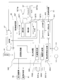
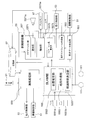
- the figure which shows the whole structure of an example of an autonomous traveling apparatus The figure which shows an example of a structure of a driving route teaching part. The figure which shows the structure of a setting part. The figure which shows the whole structure of a control part. The figure which shows the detailed structure of a traveling control part. The figure which shows the detailed structure of a control supervision part. The figure which shows an example of the coordinate system used with an autonomous running apparatus. The figure which shows an example of a definition of a 1st area
- the autonomous traveling device 100 is a cleaning machine that autonomously reproduces the taught cleaning condition and traveling route.
- “Teached cleaning condition” refers to a cleaning condition (cleaning condition) executed by a manual operation by an operator when the autonomous mobile device 100 is in a state in which it can be manually operated.
- the “taught travel route” refers to a route traveled by the autonomous travel device 100 by a manual operation (moving operation) by an operator.
- the autonomous traveling device 100 includes a traveling unit 1.
- the traveling unit 1 is a device that causes the autonomous traveling device 100 to travel.
- the traveling unit 1 has a main body B that constitutes a main body of the autonomous traveling device 100.
- the traveling unit 1 includes a traveling motor 11 and a main wheel 13 that is attached to the output rotation shaft of the traveling motor 11 and rotates according to the rotation of the traveling motor 11 at the left and right ends of the bottom of the main body B, respectively.
- the traveling unit 1 may have auxiliary wheels 15 that are rotatably attached to the left and right ends of the bottom of the main body B behind the main wheels 13, for example.
- the autonomous mobile device 100 can be made more stable.
- the auxiliary wheel 15 may be attached in front of the main wheel 13 in consideration of the position of the center of gravity of the autonomous traveling device 100 and the like.
- the autonomous traveling device 100 includes a cleaning unit 3.
- the cleaning unit 3 is a device that is provided at the bottom of the main body B and cleans the floor surface F in accordance with designated cleaning conditions.
- the cleaning unit 3 according to the present embodiment includes a cleaning liquid discharge port 31, a squeegee 33, and a cleaning member 35.
- the cleaning liquid discharge port 31 discharges the cleaning liquid (for example, water) supplied from the cleaning liquid supply tank 311 by the cleaning liquid supply pump 313 to the floor surface F on the front side of the main body B.
- the squeegee 33 is provided behind the bottom surface of the main body B, and collects the cleaning liquid remaining on the floor surface F.
- the cleaning member 35 is provided on the front side of the bottom surface of the main body B, and cleans the floor surface F by rotating on the floor surface F where the cleaning liquid exists by the rotation of the cleaning member rotating motor 351.
- the autonomous mobile device 100 can perform a cleaning operation of polishing the floor surface F with the cleaning member 35 using a cleaning liquid.
- the squeegee 33 may be provided with a suction port O2.
- the suction port O ⁇ b> 2 can suck the cleaning liquid or dust collected by the squeegee 33 and convey it to the recovery member 333 by putting the recovery member 333 in a negative pressure state by the suction motor 331.
- the autonomous mobile device 100 has a control unit 5.
- the control unit 5 is a computer system that includes a CPU, a storage device (RAM, ROM, hard disk drive, SSD, etc.), various interfaces, and the like.
- the control unit 5 performs various controls relating to the autonomous traveling device 100. The configuration of the control unit 5 will be described in detail later.
- the autonomous traveling device 100 includes a traveling route teaching unit 7.
- the travel route teaching unit 7 is a device that receives an operation of moving the travel unit 1 by an operator.
- the travel route teaching unit 7 is attached to the upper rear side of the main body B via the attachment member 8. Thereby, the operator can operate the travel route teaching unit 7 to move the travel unit 1. Details of the travel route teaching unit 7 of the present embodiment will be described later.
- the travel route teaching unit 7 may not be attached to the main body B.
- the travel route teaching unit 7 can be, for example, a controller such as a joystick. Thereby, the operator can remotely operate the autonomous mobile device 100.
- the autonomous traveling device 100 may be operable by both the traveling route teaching unit 7 and a controller that is not attached to the main body B.
- the autonomous traveling device 100 includes a setting unit 9.
- the setting unit 9 is an operation panel for performing various settings related to the autonomous mobile device 100, and is attached to the upper rear surface of the main body B.
- the setting unit 9 is provided in the vicinity of the travel route teaching unit 7. Thus, the operator can operate the setting unit 9 while operating the traveling unit 1 by operating the traveling route teaching unit 7.
- the setting unit 9 may not be attached to the main body B.
- the setting unit 9 can be a console capable of wireless communication such as a portable terminal. Thereby, the operator can set the autonomous traveling apparatus 100 remotely.
- the travel route teaching unit 7 and the setting unit 9 may be integrated. Thereby, it is possible to easily operate the traveling unit 1 and the setting unit at the same time.
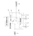
- FIG. 2 is a diagram illustrating an example of the configuration of the travel route teaching unit.
- the travel route teaching unit 7 includes handles 71a and 71b.
- the handles 71a and 71b are attached to the left and right side surfaces of the housing 73, respectively.
- the handles 71a and 71b are used when the user operates the autonomous mobile device 100.
- the operator holding the handles 71a and 71b may apply either a force that pulls the autonomous traveling device 100 toward the operator or a force that pushes the autonomous traveling device 100 through the handles 71a and 71b. it can.
- the operator can adjust the traveling direction of the autonomous traveling device 100. For example, when a force for pulling the autonomous traveling device 100 is applied to the left handle 71a when viewed from the front direction of the autonomous traveling device 100, the autonomous traveling device 100 turns to the left.
- Handles 71a and 71b are rotatably attached to the casing 73.
- the handles 71 a and 71 b are connected to the control unit 5 via a travel control command calculation unit 75.
- the travel control command calculation unit 75 converts the rotation of the handles 71 a and 71 b into an electrical signal and outputs it to the control unit 5.
- the operator can operate the autonomous traveling device 100 (the traveling unit 1) by rotating the handles 71a and 71b.
- the operator may be able to switch between forward and backward movement of the autonomous traveling device 100 by adjusting the rotation direction of the handles 71a and 71b.
- the traveling speed of the autonomous traveling device 100 may be adjustable by adjusting the amount of rotation of the handles 71a and 71b.
- the traveling direction of the autonomous traveling device 100 may be changed by changing the amount of rotation of the handle 71a and the amount of rotation of the handle 71b.
- the handle 71a may be an input interface for instructing the traveling speed in the traveling direction
- the handle 71b may be an input interface for instructing the steering angle
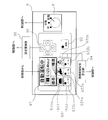
- FIG. 3 is a diagram illustrating a configuration of the setting unit.
- the setting unit 9 includes a switching unit 91.
- the switching unit 91 selects the operation mode of the autonomous traveling device 100 and outputs it to the control unit.
- the operation modes of the autonomous traveling device 100 include an autonomous cleaning mode (an example of an autonomous traveling mode) and a manual operation mode.
- the autonomous cleaning mode is an operation mode in which the autonomous traveling device 100 travels autonomously and cleans the floor surface F.
- the manual operation mode is an operation mode in which the autonomous traveling device 100 is in a state where it can be manually operated by an operator.
- the switching unit 91 can be configured by a changeover switch as shown in FIG. 3, for example.
- the autonomous cleaning mode can be selected, for example, by switching the switching unit 91 configured by a changeover switch to “automatic” shown in FIG.
- the manual operation mode can be selected, for example, by switching the switching unit 91 to “manual” shown in FIG.
- the setting unit 9 has a manual operation storage switch 92.
- the manual operation storage switch 92 is a switch for starting or ending storage of manual operation of the autonomous mobile device 100 by the operator. Specifically, when the manual operation storage switch 92 is pressed after the operation mode is set to the manual operation mode by the switching unit 91, the autonomous traveling device 100 determines the cleaning condition and the travel route executed by the manual operation of the operator.
- the manual operation teaching mode taught in (1) is started as a sub operation mode of the manual operation mode. On the other hand, when the manual operation storage switch 92 is switched during execution of the manual operation teaching mode, the manual operation teaching mode is stopped.
- the manual operation teaching mode can be started and stopped at an arbitrary timing by enabling the manual operation teaching mode to be started and stopped by the manual operation storage switch 92.
- a travel schedule 500 (an example of a route plan) desired by the operator can be created.
- the manual operation storage switch 92 for example, a push button switch as shown in FIG. 3 can be used. In this case, the manual operation storage switch 92 is switched by pressing the push button switch.
- the operation mode may be switched from the manual operation teaching mode to the manual operation mode. Thereby, even if the manual operation teaching mode is switched to the manual operation mode, the operator can manually operate the autonomous mobile device 100 continuously.
- the setting unit 9 has a cleaning condition teaching unit 93.
- the cleaning condition teaching unit 93 receives an input of the cleaning condition by the operator and outputs it to the cleaning control command calculation unit 94.
- the cleaning control command calculation unit 94 is a signal conversion circuit or a computer system that converts the cleaning condition received by the cleaning condition teaching unit 93 into a signal that can be decoded by the control unit 5 and outputs the signal to the control unit 5.
- the cleaning condition teaching unit 93 has a cleaning condition adjusting unit 931.
- the cleaning condition adjustment unit 931 includes a supply amount adjustment unit 931a that sets a supply amount S (an example of the discharge amount) of the cleaning liquid discharged from the cleaning liquid discharge port 31 as a teaching cleaning condition.
- the cleaning condition adjustment unit 931 includes a suction force adjustment unit 931b that is a push button for setting the suction force P by the suction port O2 as a teaching cleaning condition.
- the cleaning condition adjusting unit 931 includes a cleaning power adjusting unit 931c that sets the cleaning power W of the floor surface F by the cleaning member 35 as a teaching cleaning condition.
- the cleaning condition teaching unit 93 includes an operation switching unit 933.
- the operation switching unit 933 includes a supply switching unit 933a that is a push button for instructing start or stop of supply of the cleaning liquid from the cleaning liquid discharge port 31.
- the operation switching unit 933 includes a suction switching unit 933b that is a push button for instructing start or stop of suction through the suction port O2.
- the operation switching unit 933 includes a cleaning switching unit 933c that is a push button for instructing start or stop of cleaning of the floor surface F by the cleaning member 35.
- the cleaning condition teaching unit 93 has the above-described configuration, a cleaning operation of starting the suction of the cleaning liquid by the suction switching unit 933b after the supply of the cleaning liquid is stopped by the supply switching unit 933a and / or the cleaning liquid by the supply switching unit 933a. After the supply of water is stopped, the autonomous traveling device 100 can be caused to perform a cleaning operation such that the cleaning switching unit 933c starts cleaning the floor surface F after a lapse of time necessary for the cleaning liquid to adjust to the floor surface F. .
- the setting unit 9 has a setting operation unit 95.
- the setting operation unit 95 is configured by, for example, a push switch, and receives input of various settings related to the autonomous mobile device 100 and outputs the input to the control unit 5 via the setting conversion unit 96.
- the setting conversion unit 96 is a signal conversion circuit or a computer system that converts the input received by the setting operation unit 95 into a signal that can be decoded by the control unit 5.
- the setting unit 9 has a display 97.
- the display 97 displays various setting information related to the currently set autonomous traveling device 100.
- the display 97 is a display such as a liquid crystal display or an organic EL display.
- the display 97 uses, for example, the cleaning liquid supply amount S from the cleaning liquid discharge port 31, the cleaning force W of the floor surface F by the cleaning member 35, and / or the suction force P by the suction port O2 as the set cleaning conditions. indicate. Thereby, the operator can perform a cleaning operation while confirming the displayed cleaning conditions.
- the display 97 may further display the current operation mode (autonomous cleaning mode / manual operation mode / manual operation teaching mode), driving time, remaining battery level for driving the autonomous mobile device 100, and the like.
- the display 97 may display various setting procedures when performing various settings of the autonomous mobile device 100 using the setting operation unit 95. Thereby, the information regarding the autonomous mobile device 100 is visually provided to the user, and the user can operate the setting unit 9 based on the displayed information.
- the display 97 may be provided with a touch panel.
- the switching unit 91, the manual operation storage switch 92, the cleaning condition teaching unit 93, and / or the setting operation unit 95 may be realized by the touch panel.
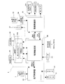
- FIG. 4 is a diagram illustrating the overall configuration of the control unit. All or some of the functional blocks of the control unit 5 described below may be realized by a program that can be executed by a computer system that configures the control unit 5. In this case, the program may be stored in the memory unit and / or the storage device. All or a part of each functional block of the control unit 5 may be realized as a custom IC such as SoC (System on Chip).
- SoC System on Chip
- the control unit 5 may be configured by one computer system or may be configured by a plurality of computer systems.
- functions realized by a plurality of functional blocks of the control unit 5 can be distributed and executed by a plurality of computer systems at an arbitrary ratio.
- the control unit 5 includes a cleaning control unit 51.
- the cleaning control unit 51 supplies power for controlling the rotation speed and output to the cleaning member rotation motor 351, the cleaning liquid supply pump 313, and the suction motor 331.
- the cleaning control unit 51 inputs a teaching cleaning condition from the cleaning condition teaching unit 93 via the cleaning control command calculation unit 94, and based on the teaching cleaning condition, The cleaning liquid supply pump 313 and the suction motor 331 are controlled.
- the cleaning control unit 51 inputs reproduction cleaning conditions (described later) from the control supervision unit 55, and controls the cleaning unit 3 based on the reproduction cleaning conditions.
- the control unit 5 includes a travel control unit 53.
- the travel control unit 53 controls the travel motor 11 based on the travel control command input from the travel route teaching unit 7 based on the travel control command based on the rotation amount and the rotation direction of the handles 71 a and 71 b or the control control unit 55.
- the traveling control unit 53 calculates the rotational speed of the traveling motor 11 based on a pulse signal output from the encoder 111 attached to the output rotation shaft of the traveling motor 11. Thereby, the traveling control unit 53 can control the traveling motor 11 while monitoring the rotational speed of the traveling motor 11 (that is, the rotational speed of the main wheel 13).
- the control unit 5 has a control supervision unit 55.
- the control supervision unit 55 supervises cleaning and traveling by the autonomous traveling device 100. Specifically, the control supervising unit 55 moves the position of the floor F on which the autonomous traveling device 100 moves based on the information acquired by the front detector 5551a, the rear detector 5551b, and / or the encoder 111. Position information indicating whether or not
- control supervision unit 55 When executing the manual operation teaching mode, the control supervision unit 55 receives the cleaning condition from the cleaning control unit 51 as the teaching cleaning condition, and creates the travel schedule 500 using the position information and the teaching cleaning condition.
- the control supervision unit 55 calculates the reproduction cleaning condition and the reproduction travel control command based on the data stored in the travel schedule 500, and the reproduction cleaning condition is sent to the cleaning control unit 51.
- a reproduction travel control command is output to travel control unit 53.
- the control unit 5 has a storage unit 57.
- the storage unit 57 is a part or all of the storage area of the storage device of the computer system that constitutes the control unit 5, and stores various information related to the autonomous mobile device 100. Specifically, the storage unit 57 stores the travel schedule 500 created by the control supervision unit 55 and various settings regarding the autonomous traveling device 100 input from the setting operation unit 95 and the setting conversion unit 96.
- the cleaning control unit 51, the travel control unit 53, and the control supervision unit 55 read various settings related to the autonomous travel device 100 and / or the travel schedule 500 stored in the storage unit 57 as necessary, and based on these. Various adjustments and controls can be performed.
- control unit 5 may include a data writing device (not shown) for storing information such as the travel schedule 500 stored in the storage unit 57 in another storage medium.
- control unit 5 may have a connection terminal to which a data writing device can be connected, such as a USB (Universal Serial Bus) port.
- a data writing device such as a USB (Universal Serial Bus) port.
- FIG. 5 is a diagram illustrating a detailed configuration of the travel control unit.
- the travel control unit 53 includes a travel switching unit 531.
- the travel switching unit 531 has three terminals d, e, and f.
- the terminal d is connected to the travel route teaching unit 7
- the terminal e is connected to the motor control unit 533
- the terminal f is connected to the control control unit 55.
- the travel switching unit 531 selects either the connection between the terminal e and the terminal d or the connection between the terminal e and the terminal f based on the operation mode selected by the switching unit 91.
- the travel switching unit 531 connects the travel route teaching unit 7 to the motor control unit 533 by connecting the terminal e and the terminal d. .
- the travel switching unit 531 transmits a signal indicating the amount of rotation and / or the direction of rotation of the handles 71a and 71b of the travel route teaching unit 7 to the motor control unit 533 when the manual operation mode or the manual operation teaching mode is executed. it can.
- the travel switching unit 531 connects the control control unit 55 to the motor control unit 533 by connecting the terminal e and the terminal f. Thereby, the traveling switching unit 531 can transmit the reproduced traveling control command output from the control supervision unit 55 to the motor control unit 533 when the autonomous cleaning mode is executed.
- the motor control unit 533 calculates the target rotation speed of the travel motor 11 based on the input rotation amount / rotation direction of the handles 71a and 71b or the reproduction travel control command, and the travel motor is driven at the target rotation speed. Driving power for rotating the motor 11 is output to the traveling motor 11.
- the motor control unit 533 calculates the actual rotational speed of the traveling motor 11 based on the pulse signal from the encoder 111 and feeds it back to calculate the driving power to be output to the traveling motor 11. Therefore, the motor control unit 533 controls the traveling motor 11 using, for example, PI (Proportional Integral) control theory, PID (Proportional Integral Differential) control theory, or the like.
- the traveling motor 11 and the main wheel 13 are provided on the left and right ends of the bottom of the main body B, respectively.
- the motor control unit 533 determines the traveling direction of the autonomous traveling device 100 by independently controlling the rotational speed and rotational direction of the two left and right traveling motors 11.
- the motor control unit 533 may be one of the plurality of computer systems. That is, only the function of the motor control unit 533 may be realized by one computer system.
- the motor control unit 533 is a motor control device using, for example, PI control theory or PID control theory.
- the control supervision unit 55 includes a teaching data acquisition unit 551.
- the teaching data acquisition unit 551 acquires teaching position information and teaching cleaning conditions at the teaching data acquisition time when the manual operation teaching mode is executed. Specifically, the teaching data acquisition unit 551 inputs teaching data acquisition time and teaching position information from the SLAM unit 555 (described later), and inputs teaching cleaning conditions at the teaching data acquisition time from the cleaning control unit 51. As the acquisition time of the teaching data, for example, the system clock of the control unit 5 can be used.
- the teaching data acquisition unit 551 outputs the acquired teaching data acquisition time, teaching position information, and teaching cleaning conditions to the travel schedule creation unit 553.
- the control supervision unit 55 includes a travel schedule creation unit 553.
- the travel schedule creation unit 553 creates a travel schedule 500 by associating the teaching position information acquired from the teaching data acquisition unit 551, the teaching cleaning condition, and the teaching data acquisition time, and stores the traveling schedule 500 in the storage unit 57.
- the control supervision unit 55 has a SLAM unit 555.
- the SLAM unit 555 includes information regarding obstacles existing in front of the autonomous mobile device 100 acquired by the front detector 5551a (FIG. 1) provided in front of the main body B, and rear detection provided in the rear of the main body B.
- On the predetermined coordinates of the autonomous traveling device 100 based on the information about the obstacle existing behind the autonomous traveling device 100 acquired by the device 5551b (FIG. 1) and the rotation amount of the traveling motor 11 acquired by the encoder 111. Information on the position (position information) is estimated.
- the front detector 5551a and the rear detector 5551b are, for example, a laser range finder (LRF) having a detection range of 180 ° or more.
- LRF laser range finder
- the information acquired by the front detector 5551a and the rear detector 5551b may be two-dimensional information indicating the position of an obstacle on a predetermined plane, or the presence of an obstacle in the height direction. It may be three-dimensional information including information representing the position.
- the detection range (detection angle and / or detection distance) of the front detector 5551a may be wider than the detection range of the rear detector 5551b. Therefore, the information regarding the obstacle which exists in the front direction of the autonomous mobile device 100 and exists more widely can be acquired.
- the front detector 5551a and the rear detector 5551b may be a TOF (Time Of Flight) camera or the like.
- TOF Time Of Flight
- the control supervision unit 55 includes a navigation unit 557.
- the navigation unit 557 guides the traveling unit 1 (the autonomous traveling device 100) to the movement start position (stored in the traveling schedule 500) or the vicinity thereof.
- the navigation unit 557 moves the travel unit 1 to the movement start position and the travel unit 1 is estimated to have reached a relatively close position from the movement start position
- the navigation unit 557 It guides from the said position to a movement start position or its vicinity.
- a detailed configuration of the navigation unit 557 and a method for guiding the traveling unit 1 to the movement start position or the vicinity thereof will be described in detail later.
- the control supervision unit 55 has a cleaning reproduction unit 559.
- the cleaning reproduction unit 559 is based on the teaching data acquisition time, the teaching cleaning condition, and the teaching position information stored in the traveling schedule 500 when the autonomous cleaning mode is executed after the traveling unit 1 reaches or near the movement start position. Then, the reproduction cleaning condition and the reproduction travel control command at a predetermined elapsed time from the start of execution of the autonomous cleaning mode are calculated and output to the cleaning control unit 51 and the travel control unit 53, respectively.
- the SLAM unit 555 executes position (position information) estimation of the traveling unit 1 (autonomous traveling device 100) and creation of map information by a SLAM (Simultaneous Localization and Mapping) method.
- the SLAM unit 555 has a map creation unit 5553.
- the map creation unit 5553 uses the information on the front obstacle (for example, a wall) acquired by the front detector 5551a and the information on the rear obstacle acquired by the rear detector 5551b. Create information.
- the map information is used when the position estimation unit 5555 estimates position information. As map information, there are a local map and a global map.
- the local map is map information related to obstacles (existing positions) around the traveling unit 1.
- the local map is created by coordinate-converting the information about the front obstacle acquired by the front detector 5551a and the information about the rear obstacle acquired by the rear detector 5551b as necessary.
- the global map is map information related to an obstacle (existing position) present in an environment (moving environment) in which the traveling unit 1 moves.
- the global map is generated based on the local map acquired when the manual operation teaching mode is executed. Therefore, the local map acquired at the time of executing the manual operation teaching mode is stored in the storage unit 57 in association with the time (for example, the teaching data acquisition time) when it is acquired.
- the local map may be stored in the storage unit 57 in association with the estimated position of the traveling unit 1 when the local map is acquired.
- the map creation unit 5553 of this embodiment arranges a local map associated with a certain elapsed time and a local map associated with a time in the vicinity of the certain elapsed time at the position of the traveling unit 1 at each elapsed time. By placing the center of the local map at the position of the traveling unit 1 at the corresponding elapsed time, map information representing a part of the moving environment (for example, a range necessary for position estimation) Generate as a map. Also, the map creation unit 5553 deletes a part of the global map generated in the past that is no longer necessary for position estimation.
- the “circular route problem” (part of the global map generated in the initial stage and part of the global map generated in the final stage match. If the problem of disappearing does not occur, map information representing the entire mobile environment may be generated as a global map.
- the global map may be created using dedicated software, CAD, or the like and stored in the storage unit 57.
- the global map created by the software or the like is converted into data that can be interpreted by the control unit 5 of the traveling unit 1.
- the SLAM unit 555 includes a position estimation unit 5555.
- the position estimation unit 5555 is based on the global map generated by the map creation unit 5553, the local map, and the rotation amount of the travel motor 11, and the location of the travel unit 1 on a predetermined coordinate and the travel unit at the position. Position information related to one posture is estimated.
- the position information is estimated as follows.
- a position where the traveling unit 1 moves from an (estimated) position at a predetermined time ( denoted as time tk) and arrives at the next time ( denoted as time tk + 1 ) is determined.
- the position estimation unit 5555 the rotation amount of the main wheel 13 between the number of pulses output from the encoder 111 during the period from the time t k until the time t k + 1, from the time t k until the time t k + 1
- the travel distance and the posture change of the traveling unit 1 due to the rotation of the main wheel 13 are estimated based on the rotation amount (dead reckoning).
- the position estimation unit 5555 corresponds to a posterior probability at time t k (corresponding to a probability distribution representing a relationship between the position of the traveling unit 1 and the probability that the traveling unit 1 exists at the position at time t k ). Is moved by the moving distance and the posture change of the traveling unit 1 due to the rotation of the main wheel 13, and the prior probability at the time t k + 1 is calculated.
- the position estimation unit 5555 expands the width (standard deviation) of the probability distribution of the posterior probability after the movement by the movement distance and the posture change due to the rotation of the main wheel 13, and the time t k + 1. It is good also as prior probability in. Thereby, the prior probability considering the slip between the main wheel 13 and the floor surface F can be calculated.
- the position estimating unit 5555 obtains a local map and the global map from the mapping unit 5553 at time t k + 1, and map matching and a local map and a global map at time t k + 1, time t k + estimating the position information of the traveling unit 1 in one.
- local maps at time t k + 1 are arranged at several positions in the vicinity of the estimated position calculated based on the rotation amount of the main wheel 13, and the local map Is rotated by an angle corresponding to the posture change that can be taken around its center, and map matching is performed.
- the position estimation unit 5555 is based on the result of the map matching, and the likelihood (corresponding to the relationship between the position where the local map information is arranged and the degree of coincidence between the global map and the local map information at the position) Is calculated.
- the position estimation unit 5555 by multiplying the prior probability of the likelihood and the time t k + 1, to calculate the posterior probability at time t k + 1.
- the position estimation unit 5555 has a position and orientation at which the posterior probability at the time t k + 1 is the maximum value, that is, a position where the possibility that the traveling unit 1 is most likely to exist, and the traveling unit 1 at the position. Is estimated as the position (estimated position) of the traveling unit 1 and the position (estimated position) at the position t k + 1 at time t k + 1 .
- the posterior probability at time t k + 1 is used as the prior probability in the next position estimation.
- the position estimation unit 5555 performs position estimation using the movement distance based on the rotation amount of the main wheel 13 and the map information obtained using the front detector 5551a and the rear detector 5551b.
- an error included in the movement distance based on the rotation amount of the main wheel 13 mainly due to slippage between the main wheel 13 and the floor surface F
- an error included in the map information mainly
- the position estimation can be performed with a small amount of compensation in a complementary manner (due to noise components included in the information acquired by the front detector 5551a and the rear detector 5551b).
- the SLAM unit 555 includes an elapsed time determination unit 5557.
- the elapsed time determination unit 5557 determines the teaching data acquisition time and the elapsed time from the start of execution of the autonomous cleaning mode. In the present embodiment, the elapsed time determination unit 5557 determines the teaching data acquisition time by using a clock function such as a microcomputer system constituting the control unit 5, for example.
- the elapsed time from the start of execution of the autonomous cleaning mode is determined based on the position information estimated by the position estimation unit 5555. Specifically, for example, the teaching data acquisition time associated with the position information closest to the position information of the traveling unit 1 estimated by the position estimating unit 5555 among the position information stored in the traveling schedule 500 is set. And elapsed time.
- the elapsed time may be calculated by extracting two pieces of position information close to the position information estimated by the position estimation unit 5555 from the travel schedule 500 and linearly interpolating the two position information. Good. Thereby, a more accurate elapsed time can be calculated.
- the autonomous mobile device 100 By determining the elapsed time from the start of execution of the autonomous cleaning mode based on the position information estimated by the position estimation unit 5555, the autonomous mobile device 100 is instructed to teach teaching cleaning conditions when executing the autonomous cleaning mode. Cleaning work can be reproduced autonomously while accurately grasping the timing and place of execution. For example, at the time of execution of the autonomous cleaning mode, when the autonomous traveling device 100 decreases or stops moving that is not indicated in the traveling schedule 500 for the purpose of avoiding an obstacle, the cleaning work proceeds with time. Therefore, it is possible to avoid that the cleaning work that is not originally performed at the current position is autonomously performed.
- FIG. 6 is a diagram illustrating a detailed configuration of the navigation unit.
- the navigation unit 557 includes a notification unit 5571.
- the estimated position of the traveling unit 1 is in the first region A1
- the estimated posture of the traveling unit 1 is the first. If it is within one angle range ⁇ 1 , this is notified by, for example, making a sound through the speaker 5571a.
- the first area A1 is defined as an area that is regarded as a position relatively close to the movement start position P 0 in the navigation unit 557.
- the first region A1 is defined as a region including the movement start position P 0 and having a predetermined area. Further, the first area A1 is defined as an area for determining that the navigation unit 557 starts guiding the traveling unit 1 if the traveling unit 1 exists in the first region A1.
- the first angle range ⁇ 1 is defined as an angle range including the attitude of the traveling unit 1 at the movement start position P 0 (hereinafter referred to as a movement start attitude). That is, the first angle range ⁇ 1 is an angle range in which the posture of the traveling unit 1 is considered to be relatively close to the movement start posture if the posture of the traveling unit 1 is within this angle range.
- the first angle range ⁇ 1 is defined as an angle range for determining that the navigation unit 557 starts guiding the traveling unit 1 when the traveling unit 1 is in the first angle range ⁇ 1 .
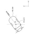
- the first area A1 and the first angle range ⁇ 1 of the present embodiment are defined as follows in an xy coordinate system (an example of predetermined coordinates) as shown in FIG. 7, for example.
- the xy coordinate system shown in FIG. 7 defines the x-axis in the horizontal direction of FIG. 7 and the y-axis in the vertical direction perpendicular thereto.
- An angle (posture ⁇ ) that increases counterclockwise from the x axis is defined with an angle parallel to the x axis being zero.
- an angle formed by the x-axis and the front-rear direction of the autonomous traveling device 100 (moving direction when going straight) is defined as the “posture” of the autonomous traveling device 100.
- FIG. 7 is an example of a coordinate system used in the autonomous mobile device.
- the first region A1 can be defined as a region within a circle having a radius R 1 with the movement start position P 0 as the center.
- the “predetermined area” of the first region A1 is ⁇ R 1 2 .
- the first angle range theta 1 is defined as the range of orientation theta of running portion 1 when the inequality of ⁇ 0 - ⁇ 1/2 ⁇ ⁇ ⁇ ⁇ 0 + ⁇ 1/2 is satisfied.
- FIG. 8 is a diagram illustrating an example of definitions of the first region, the first angle range, the second region, and the second angle range.
- the notification unit 5571 indicates that the current estimated position of the traveling unit 1 is in the position (in the region) where the navigation unit 557 starts guidance of the traveling unit 1. Can notify the surroundings.
- the first area A1 does not include the movement start position P 0 and / or the second area A2 described later, but is defined as an area that is considered to be a relatively close position from the movement start position P 0. May be.
- the first area A1 may be defined in front of the second area A2 without being forcibly included.
- navigation is performed navigation from the back of the movement start position P 0 and / or the second region A2 may fail. Accordingly, when there are many obstacles in front of the movement start position P 0 and / or the second area A2, navigation is started from the first area A1 defined in front of the second area A2 and not including the second area A2. , Navigation failure can be suppressed.
- the first angle range theta 1 is, although not include a second angle range theta 2, may be defined as an angle range in the vicinity of the second angle range theta 2.
- the navigation unit 557 includes a navigation amount calculation unit 5573.
- the navigation amount calculating unit 5573 guides the traveling unit 1 in the second area A2 and the posture in the second area A2 is the second. An operation amount of the traveling unit 1 for guiding the traveling unit 1 to be within the angle range ⁇ 2 is calculated.
- the second region A2 is defined as a region within a circle having a radius R 2 (R 2 ⁇ R 1 ) centered on the movement start position P 0 , for example.
- the second region A2 is included in the first region A1, and can be defined as a region including the movement start position P 0.
- the second angle range theta 2 is, for example, ⁇ 0 - ⁇ 2/2 ⁇ ⁇ ⁇ ⁇ 0 + ⁇ 2/2 ( ⁇ 2 ⁇ 1) and of the running portion 1 of the orientation theta when inequality holds for Defined as a range.
- the second angle range ⁇ 2 can be defined as an angle range that is included in the first angle range ⁇ 1 and includes the movement start posture ⁇ 0 .
- Running portion 1 is present in the second region A2 above and, when the posture ⁇ is running portion 1 is determined that the angle of the second angular range ⁇ 2, the control unit 5, the travel It is determined that the part 1 is present at or near the movement start position P 0 and the attitude ⁇ of the traveling part 1 is the movement start attitude or an angle near the movement start position P 0 , and the autonomous traveling device 100 is autonomous The operation can be started.
- the first area A1, the first angle range ⁇ 1 , the second area A2, and the second angle range ⁇ 2 are mathematical expressions (expressions representing the areas) in the xy coordinate system that define these areas and angle ranges. Alternatively, it is defined as an inequality, and the mathematical expression or inequality is stored in the storage unit 57.
- first area A1, the first angle range ⁇ 1 , the second area A2, and the second angle range ⁇ 2 are stored as coordinate values and angles of the boundary points of these areas and angle ranges. 57 may be stored.
- the estimated position of the running portion 1 is in the first area A1, and, when the estimated position of the running portion 1 is in the first angular range ⁇ 1, the travel unit 1
- the distance between the current estimated position and the movement start position P 0 stored in the travel schedule 500 is calculated as the travel distance to which the travel unit 1 should be guided.
- the navigation amount calculation unit 5573 calculates the difference between the current estimated posture of the traveling unit 1 and the movement start posture ⁇ 0 stored in the traveling schedule 500 as the direction in which the traveling unit 1 should be guided.
- the navigation unit 557 has a notification unit 5575.
- Notification unit 5575 induces travel unit 1 in the second region A2, and the operation of the attitude ⁇ in the second region A2 induces running portion 1 so that the second angle range ⁇ 2, the operator To inform.
- the notification unit 5575 outputs the movement distance calculated by the navigation amount calculation unit 5573 to guide the traveling unit 1 and the direction to guide the traveling unit 1 through the speaker 5571a. To inform.
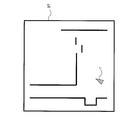
- the notification unit 5575 may visually display the movement distance and direction to which the traveling unit 1 calculated by the navigation amount calculation unit 5573 should be guided. Specifically, for example, as illustrated in FIG. 9, the notification unit 5575 displays a camera image representing an environment (front) of the traveling unit 1 acquired by a camera 5575a provided in front of the main body B. displays 97, directed onto the camera image, the driving unit 1 induced in the second region A2, and the running portion 1 so that orientation ⁇ in the second region A2 is a second angular range ⁇ within 2 You may display the operation for doing.
- FIG. 9 is a diagram illustrating an example in which an operation for guiding the traveling unit is displayed on the camera image.
- reporting part 5575 is a map (for example, movement) comprised by the information regarding the obstacle which exists in the circumference
- a global map stored in the storage unit 57 as representing the environment around the start position) is displayed on the display 97, the traveling unit 1 is guided into the second area A2 on the map, and the second area orientation ⁇ in the A2 may display an operation for inducing running portion 1 so that the second angle range ⁇ 2.
- the direction of the apex of the triangle representing the traveling unit 1 is the direction in which the traveling unit 1 should be guided.
- FIG. 10 is a diagram illustrating an example in which an operation for guiding a traveling unit is displayed on a map.
- the notification unit 5575 may represent the movement start position and the movement start posture with a triangle representing the traveling unit 1 on the map displayed on the display 97.
- the direction in which the apex of the triangle faces is the movement start posture.
- the center position of the map displayed on the display 97 may be the current estimated position of the traveling unit 1.
- the notification unit 5575 may display information representing the environment around the movement start position other than the map created by the map creation unit 5553 on the display 97. For example, a map created based on information obtained with a 3D-TOF camera, a map created based on information obtained with an infrared sensor, and created based on information obtained with an ultrasonic sensor Map, etc. can be displayed.
- the visual information (camera image, global map, etc.) displayed on the notification unit 5575 is when the autonomous traveling device 100 is installed (for example, when traveling for the first time or traveling environment). May be acquired in advance and stored in the storage unit 57 or the like. In this case, position information (coordinate values) or the like may be associated with the visual information acquired in advance.
- the notification unit 5575 reads visual information corresponding to the current position of the traveling unit 1 and superimposes information necessary for navigation on the visual information and displays the information on the display 97.
- the notification unit 5575 may display both visual information acquired in advance during installation and the visual information acquired during traveling of the traveling unit 1 on the display 97. Good.
- the notification unit 5575 displays the global map acquired during traveling and the camera image acquired in advance on the display 97 (overlapping or displaying in a divided individual area), and any information Information necessary for navigation may be superimposed and displayed on the top.
- the operator of the autonomous traveling device 100 guides the traveling unit 1 in the second area A2, and the second area orientation ⁇ in the A2 is an operation for inducing traveling portion so that the second angle range ⁇ 2, can be visually confirmed.
- the operator according to visually confirm the operation, the travel unit 1 is easily induced by the second region A2, and the orientation ⁇ in the second region A2 and the second angle range ⁇ within 2
- the traveling unit 1 can be guided more easily.
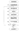
- FIG. 11 is a flowchart showing the basic operation of the autonomous mobile device.
- the control unit 5 confirms the state of the switching unit 91 (step S1).
- switching unit 91 has selected “automatic” (in the case of “autonomous cleaning mode” in step S 1)
- autonomous cleaning mode is executed (step S 2) and autonomous according to travel schedule 500 stored in storage unit 57.
- the traveling device 100 autonomously performs a cleaning operation.
- the control unit 5 determines that the operation mode to be executed is the manual operation mode.
- the control unit 5 shifts the operation mode to the manual operation teaching mode (step S4). .
- the cleaning work by the operator after the timing when the manual operation storage switch 92 is pressed is stored as the travel schedule 500.
- step S3 when the manual operation storage switch 92 is not pressed (in the case of “No” in step S3), execution of the manual operation mode in which the cleaning operation of the autonomous mobile device 100 by the operation of the operator is not stored is maintained (step S5) ).
- step S4 the control unit 5 monitors whether or not the manual operation storage switch 92 has been pressed.
- the operation mode is switched to the manual operation mode at that timing, and the cleaning work after that timing is not stored in the travel schedule 500. That is, by pressing the manual operation storage switch 92 during execution of the manual operation teaching mode, the operator can stop the storage (teaching) at an arbitrary timing during the cleaning operation.
- the autonomous traveling device 100 has the autonomous cleaning mode, the manual operation mode, the operation mode selection in the switching unit 91, and whether or not the manual operation storage switch 92 is pressed.
- the manual operation teaching mode can be executed.
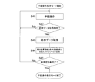
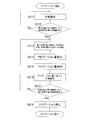
- FIG. 12 is a flowchart showing the operation in the manual operation teaching mode.
- the manual operation of the autonomous mobile device 100 is started after the manual operation storage switch 92 is pressed, or the manual operation storage switch 92 is pressed during the manual operation (step S41), and the manual operation is taught.
- creation of the travel schedule 500 is started.
- the teaching data acquisition unit 551 has the cleaning liquid output to the cleaning liquid supply pump 313 by the cleaning control unit 51 at that timing.
- the supply amount S, the suction force P output to the suction motor 331, and the cleaning force W output to the cleaning member rotation motor 351 are input as teaching cleaning conditions at an elapsed time of zero.
- the position estimation unit 5555 is instructed to estimate the position information of the traveling unit 1 at the elapsed time 0, and the estimated position information is input as teaching position information.
- the estimated position and estimated posture at the elapsed time 0 are a movement start position P 0 (coordinate values (x 0 , y 0 )) and a movement start posture ⁇ 0 , respectively.
- the travel schedule creation unit 553 inputs the teaching position information and the teaching cleaning condition at the elapsed time 0 from the teaching data acquisition unit 551 and stores the teaching position information and the teaching cleaning condition in the storage unit 57 in association with the elapsed time 0.
- the travel schedule 500 is used.
- the teaching data acquisition unit 551 monitors the elapsed time determined by the elapsed time determination unit 5557, and if the elapsed time is the teaching data acquisition time (in the case of “Yes” in step S42), the position Position information at the teaching data acquisition time is input from the estimation unit 5555 as teaching position information, and a cleaning condition at the teaching data acquisition time is input from the cleaning control unit 51 as teaching cleaning conditions (step S43). Thereby, teaching position information and teaching cleaning conditions can be acquired every teaching data acquisition time.
- the teaching data acquisition time can be set at a predetermined time (for example, 500 ms) after the manual operation storage switch 92 is pressed.
- the travel schedule creation unit 553 stores the teaching position information and the teaching cleaning condition acquired by the teaching data acquisition unit 551 in the traveling schedule 500 in association with the acquired teaching data acquisition time (step S44). By repeating the above steps S41 to S44 until the cleaning operation by the operator is completed (until “Yes” in step S45), teaching position information and teaching from the start to the end of the cleaning operation by the operator The cleaning conditions can be stored as the travel schedule 500.
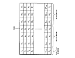
- FIG. 13 is a diagram illustrating an example of a travel schedule.
- T 0 , T 1 ,... T n are teaching data acquisition times.
- the teaching data acquisition time T 0 is set to 0.
- (X n , y n , ⁇ n ) are teaching position information at the corresponding teaching data acquisition time.
- (X n , y n ) are position information (coordinates) of the autonomous mobile device 100 on the xy coordinates at the corresponding teaching data acquisition time.
- ⁇ 0 , ⁇ 1 ,... ⁇ n are postures of the autonomous traveling device 100 at the corresponding teaching data acquisition time.
- S 0 , S 1 ,... S n are supply amounts of the cleaning liquid at the corresponding teaching data acquisition time.
- W 0 , W 1 ,... W n are the cleaning power of the floor surface F at the corresponding teaching data acquisition time.
- P 0 , P 1 ,... P n are suction forces of the suction port O2 at the corresponding teaching data acquisition time.
- FIG. 14 is a flowchart showing the operation of the autonomous mobile device when the autonomous cleaning mode is executed.
- the navigation unit 557 guides the traveling unit 1 to the movement start position and the movement start posture stored in the traveling schedule 500 or in the vicinity thereof.
- the operation is started (step S21).
- the navigation operation executed in step S21 will be described in detail later.
- the autonomous traveling device 100 autonomously travels and cleans the floor F according to the traveling schedule 500. Start. Specifically, the autonomous cleaning mode is executed as follows.
- the SLAM unit 555 acquires information on the front obstacle and information on the rear obstacle from the front detector 5551a and the rear detector 5551b (step S22).
- the position estimation unit 5555 is based on the rotation amount of the travel motor 11 measured by the encoder 111, the global map, and the local map obtained based on the information acquired in step S21. Is estimated on the xy coordinates (step S23). For example, the position of the autonomous driving apparatus 100, on the x-y coordinate, and (x m ', y m' , ⁇ m ') is estimated to be.
- the elapsed time determination unit 5557 determines the elapsed time t m from the start of execution of the autonomous cleaning mode (step S24), and the cleaning reproduction unit 559 reproduces the traveling control at the elapsed time t m .
- the command and the reproduction cleaning condition are calculated as follows (step S25).
- the cleaning reproduction unit 559 reads the position information (x L + 1 , y L + 1 , ⁇ L + 1 ) associated with the next teaching data acquisition time T L + 1 from the travel schedule 500, and the elapsed time
- the reproduction travel control command at the time t m is determined based on the difference between the estimated position information and the target position information (x L + 1 ⁇ x m ′, y L + 1 ⁇ y m ′, ⁇ L + 1 ⁇ m Calculate based on ').
- the cleaning reproducing unit 559 the cleaning condition associated with teaching data acquisition time T L (S L, W L , P L) reads from the travel schedule 500, the cleaning conditions (S L, W L, P L) Is determined as a reproduction cleaning condition at the elapsed time t m .
- the cleaning reproduction unit 559 After calculating the reproduction travel control command and the reproduction cleaning condition, the cleaning reproduction unit 559 outputs the reproduction travel control command to the travel control unit 53, and outputs the reproduction cleaning condition to the cleaning control unit 51 (step S26).
- the traveling control unit 53 moves the traveling unit 1 autonomously according to the traveling schedule 500 by controlling the traveling motor 11 based on the received reproduced traveling control command.
- the cleaning control part 51 controls the cleaning part 3 autonomously according to the driving schedule 500 by controlling the cleaning part 3 based on the received reproduction cleaning conditions.
- the cleaning reproducing unit 559 After controlling the traveling unit 1 and the cleaning unit 3 based on the reproduced traveling control command and the reproduced cleaning condition, respectively, the cleaning reproducing unit 559 checks whether or not all the cleaning operations stored in the traveling schedule 500 have been executed (step S27). ). Whether or not all the cleaning operations stored in the travel schedule 500 have been completed can be confirmed, for example, by detecting an identifier at the end of the travel schedule 500 (for example, an identifier indicating “end of file”).
- step S27 As long as it is determined that all the cleaning operations stored in the travel schedule 500 have not been executed (“No” in step S27), the above steps S22 to S26 are repeatedly executed and stored in the travel schedule 500. When it is determined that all cleaning operations have been performed (in the case of “Yes” in step S27), the execution of the reproduction cleaning mode is terminated. Thereby, the autonomous mobile device 100 can faithfully reproduce the cleaning work stored in the travel schedule 500.
- the user is instructed to stop the reproduction cleaning mode. In some cases, the execution of the reproduction cleaning mode may be stopped.
- the cleaning reproduction unit 559 calculates the reproduction cleaning condition and the reproduction travel control command based on the travel schedule 500 created by the travel schedule creation unit 553, respectively.
- the autonomous traveling device 100 can autonomously execute a cleaning operation.
- FIG. 15 is a flowchart showing the navigation operation according to the first embodiment.
- the travel switching unit 531 of the travel control unit 53 connects the terminal e and the terminal d.
- navigation of the travel unit 1 is started from an arbitrary position (for example, a charging station for charging a battery provided in the autonomous travel device 100). Move to the first area A1. Further, the posture of the traveling unit 1 is set to an angle within the first angle range ⁇ 1 by manual operation (step S211).
- the traveling unit 1 by a manual operation by moving in the first region A1, while the attitude ⁇ of the running portion 1 and the angle of the first angle range ⁇ 1, the navigation unit 557, at predetermined time intervals, the position estimation unit From 5555, the current estimated position and estimated posture of the traveling unit 1 are acquired.
- the navigation unit 557 determines whether the current estimated position of the traveling unit 1 exists in the first area A1 and the current estimated posture is in the first angle range ⁇ 1 (step S212).
- the navigation unit 557 determines that the coordinate value (x, y) of the current estimated position in the xy coordinate system is (x ⁇ x 0 ) 2 + (y ⁇ y 0 ) 2 ⁇ R 1 2 meets inequality, and determines whether theta current estimated pose satisfy ⁇ 0 - ⁇ 1/2 ⁇ ⁇ ⁇ ⁇ 0 + ⁇ 1/2 inequality.
- the navigation unit 557 may instruct the position estimation unit 5555 to expand the estimated range of the estimated position and estimated posture while executing the above step S212. Specifically, for example, it may be instructed to expand the range of coordinates where the local map is arranged in map matching and expand the rotation angle range of the local map at each arrangement position of the local map.
- the operator determines the current position of the traveling unit 1. By grasping and manually operating, the traveling unit 1 can be moved into the first area A1, and the posture ⁇ of the traveling unit 1 can be set to an angle within the first angle range ⁇ 1 .
- the maximum speed at which the traveling unit 1 can travel may be reduced.
- the estimation range of the estimated position and the estimated posture is expanded, a larger amount of calculation is required for estimating the estimated position and the estimated posture. As a result, it takes time until the estimated position and the estimated posture are specifically calculated. Therefore, by reducing the maximum speed of the traveling unit 1 in such a case, it is possible to avoid the calculation of the estimated position and the estimated posture from catching up with the manual operation by the operator. As a result, it is possible to avoid a deviation between the estimated position and the estimated posture and the actual position and posture of the traveling unit 1.
- step S212 When it is determined as a result of manual operation of the traveling unit 1 by the operator that the estimated position of the traveling unit 1 exists in the first area A1 and the estimated posture ⁇ is within the first angle range ⁇ 1 (step S212).
- the notification unit 5571 emits a predetermined sound or voice from the speaker 5571a, for example, the traveling unit 1 exists in the first region A1 and the posture is within the first angle range ⁇ 1 . Then, it is notified that the navigation operation of the traveling unit 1 is possible (step S213).
- an operator who has manually operated the traveling unit 1 can confirm that the traveling unit 1 has been moved to a position and posture where navigation operation is possible.
- the navigation unit 557 After running portion 1 becomes navigable state, the navigation unit 557, a traveling unit 1 is moved in the second region A2, the posture of the traveling unit 1 for the angle of the second angular range ⁇ within 2 Start navigation.
- the navigation amount calculating unit 5573 is, requires a distance between the current estimated position of the running portion 1 and the movement start position P 0, in order to move the running portion 1 on the movement start position P 0 It is calculated as a navigation amount that represents a long moving distance. Further, the difference between the currently estimated position theta movement start position theta 0 of the traveling unit 1, it is calculated as a navigation quantity representing the posture variation required the posture of the traveling unit 1 to the movement start position theta 0 ( Step S214).
- the navigation amount calculation unit 5573 outputs the calculated navigation amount to the notification unit 5575 (step S215).
- the notification unit 5575 generates a sound signal for notifying the input navigation amount by sound, and outputs the sound signal to the speaker 5571a.
- the speaker 5571a emits, for example, “Please proceed ⁇ m in the direction of ⁇ ” with the navigation amount as voice.
- the notification unit 5575 when the notification unit 5575 displays the navigation amount on the display 97, the notification unit 5575 acquires a current camera image around the autonomous mobile device 100 by the camera 5575a.
- a camera image acquired in advance and stored in the storage unit 57 or the like is read out.
- the acquired or read camera image represents character information indicating a navigation amount such as “Please proceed ⁇ m in the ⁇ direction” and the direction in which the traveling unit 1 should be operated.
- An image signal may be generated by superimposing the arrow and output to the display 97. Thereby, as shown in FIG. 9, the navigation amount can be displayed on the camera image.
- the navigation amount calculation unit 5573 calculates the navigation amount, and the position estimation unit 5555 On the other hand, it may be instructed to reduce (return) the estimated range of the estimated position and estimated posture.
- the traveling route teaching unit 7 and the like Based on the notification from the notification unit 5575, the operator who has grasped the navigation amount for moving the traveling unit 1 to or near the movement start position P 0 and the movement start posture ⁇ 0, the traveling route teaching unit 7 and the like according to the navigation amount Operate manually.
- the control signal based on the manual operation is output to the motor control unit 533 via the travel switching unit 531, the travel control unit 53 moves toward the movement start position P 0 and the movement start posture ⁇ 0 or in the vicinity thereof.
- the traveling unit 1 is moved (step S216).
- the navigation unit 557 acquires the current estimated position and estimated posture of the traveling unit 1 from the position estimation unit 5555 at every predetermined time during the execution of the above steps S213 to S216.
- the navigation unit 557 determines whether the current estimated position of the traveling unit 1 exists in the second region A2 and the current estimated posture is in the second angle range ⁇ 2 (step S217). Specifically, for example, the navigation unit 557 determines that the coordinate value (x, y) of the current estimated position in the xy coordinate system is (x ⁇ x 0 ) 2 + (y ⁇ y 0 ) 2 ⁇ R 2 2. meets inequality, and determines whether theta current estimated pose satisfy ⁇ 0 - ⁇ 2/2 ⁇ ⁇ ⁇ ⁇ 0 + ⁇ 2/2 inequality.
- step S217 When it is determined that the current estimated position of the traveling unit 1 exists in the second area A2 and the current estimated posture is in the second angle range ⁇ 2 (in the case of “Yes” in step S217), Since the traveling unit 1 has arrived at or near the movement start position P 0 and the movement start posture ⁇ 0 , it is determined that the autonomous cleaning mode can be executed.
- the navigation unit 557 stops guiding the traveling unit 1 (step S218). Specifically, the navigation amount calculation unit 5573 stops the calculation and output of the navigation amount, and the notification unit 5575 stops the notification of the navigation amount. Thereby, the operator can grasp that the traveling unit 1 has been moved to the movement start position P 0 and the movement start posture ⁇ 0 or the vicinity thereof, and can stop the manual operation of the traveling unit 1. That is, the operator reliably allowed to reach the second area A2 of the travel unit 1, to ensure the attitude ⁇ of the traveling unit 1 can the angle of the second angular range ⁇ 2.
- the notification unit 5575 terminates the navigation because “the movement start position has been reached. You may be informed. Thus, the operator can more clearly grasp that the traveling unit 1 can be moved to the movement start position P 0 and the movement start posture ⁇ 0 or the vicinity thereof.
- Step S217 when it is not determined that the current estimated position of the traveling unit 1 exists in the second region A2 and the current estimated posture is in the second angle range ⁇ 2 (that is, Step S217).
- Step S217 for example, when the operator stops the traveling unit 1 and presses a button (not shown) provided in the setting unit 9, the calculation of the navigation amount is performed again. The amount of navigation is notified.
- the traveling unit Stop induction 1 when the operator stops the traveling unit 1 and presses a button (not shown) provided in the setting unit 9, the calculation of the navigation amount is performed again. The amount of navigation is notified.
- the traveling unit Stop induction 1 for example, when the operator stops the traveling unit 1 and presses a button (not shown) provided in the setting unit 9, the calculation of the navigation amount is performed again. The amount of navigation is notified.
- the traveling unit Stop induction 1 if the operator continues to operate the traveling unit 1, and it is determined that the position of the traveling unit 1 exists in the second region A2 and the posture is in the second angle range
- the traveling unit 1 when the traveling unit 1 is moved to the movement start position P 0 in order to execute the autonomous cleaning mode, the estimated position of the traveling unit 1 is within the first region A1, and When the estimated posture of the traveling unit 1 is within the first angle range ⁇ 1 , the navigation unit 557 guides the traveling unit 1 to a position in the second region A2, and the posture of the traveling unit 1 is the second. It induces running portion 1 so as to be angular range ⁇ 2. That is, the error between the current position of the traveling unit 1 and the movement start position P 0 is within a certain range, and the error between the current position of the traveling unit 1 and the movement start posture ⁇ 0 is within a certain range.
- the autonomous traveling device 100 can be reliably moved to the movement start position P 0 and the movement start posture ⁇ 0 or the vicinity thereof, and the autonomous cleaning device 100 can be reliably started in the autonomous cleaning mode. Further, the operator does not need to move the autonomous mobile device 100 to the movement start position P 0 and the movement start posture ⁇ 0 accurately based only on his / her own judgment by the above navigation operation. As a result, it is possible to reduce the operator's workload required until the autonomous traveling device 100 starts the autonomous traveling mode.
- the change in the posture of the unit 1 (the rotation operation of the traveling unit 1) can be reduced.
- the travel unit 1 is moved into the first region A1 by the operation of the operator, and the travel unit If the posture of 1 is an angle within the first angle range ⁇ 1 , the traveling unit 1 may autonomously move to the movement start position P 0 and the movement start posture ⁇ 0 or in the vicinity thereof.
- the navigation amount calculation unit 5573 calculates a navigation amount, calculates a navigation travel control command based on the navigation amount, and sends the navigation control command to the travel control unit 53.
- FIG. 16 is a diagram illustrating a configuration of a control control unit according to the second embodiment.
- FIG. 17 is a flowchart showing a navigation operation according to the second embodiment.
- the running portion 1 is moved in the first region A1, the posture of the running portion 1 and the angle of the first angle range ⁇ 1 (Steps S211 ′ to S212 ′).
- the travel unit 1 is present in the first region A1, when the posture of the running portion 1 is in the first angular range ⁇ 1, the notification unit 5571 that This may be notified by voice or the like. Thereby, it is possible to notify the operator and / or persons around the autonomous mobile device 100 that the autonomous navigation operation is started.
- the navigation amount calculation unit 5573 calculates the navigation amount of the traveling unit 1 in the same manner as in the first embodiment (step S213 ′).
- the navigation amount may be notified to the notification unit 5575 after the navigation amount is calculated.
- “traveling ⁇ m in the direction of ⁇ ” informs how the traveling unit 1 will move in the future. Thereby, the travel distance and the travel direction of the travel unit 1 can be notified to the operator of the autonomous travel device 100 and / or the surrounding persons.
- the travel switching unit 531 connects the terminal e and the terminal f.
- the navigation amount calculation unit 5573 Based on the calculated navigation amount, the navigation amount calculation unit 5573 outputs the output to the traveling control unit 53 in order to move the traveling unit 1 to the movement start position P 0 and change the posture of the traveling unit 1 to the movement start posture ⁇ 0.
- a navigation travel control command to be calculated is calculated.
- the navigation amount calculation unit 5573 first calculates a navigation travel control command for directing the travel unit 1 in the direction of the movement start position P 0 and outputs the navigation travel control command to the travel control unit 53 (step S214 ′). At this time, the navigation amount calculation unit 5573 first calculates the posture when the traveling unit 1 faces the direction of the movement start position P 0 . For example, assuming that the current estimated position of the traveling unit 1 is (x ′, y ′), the posture when the traveling unit 1 is directed toward the movement start position P 0 is tan ⁇ 1 ((( y 0 ⁇ y ′) / (x 0 ⁇ x ′)).
- the navigation amount calculation unit 5573 generates a navigation travel control command based on the difference between the current estimated posture ⁇ of the travel unit 1 and the angle tan ⁇ 1 ((y 0 ⁇ y ′) / (x 0 ⁇ x ′)). Is output to the travel control unit 53. Thereby, the traveling control unit 53 rotates the traveling unit 1 in the direction of the movement start position P 0 based on the navigation traveling control command.
- the navigation amount calculation unit 5573 calculates a navigation travel control command for moving the travel unit 1 straight from the current position to the movement start position P 0 and outputs the navigation travel control command to the travel control unit 53 (step S215 ′).
- This navigation travel control command can be calculated based on the distance between the current estimated position of the travel unit 1 and the movement start position P 0 .
- the travel control unit 53 that has received this navigation travel control command moves the travel unit 1 straight to the movement start position P 0 .
- the navigation amount calculation unit 5573 calculates a navigation travel control command for directing the travel unit 1 in the direction of the movement start posture ⁇ 0 at the current position, and outputs the navigation travel control command to the travel control unit 53 ( Step S216 ′).
- This navigation travel control command can be calculated based on the difference between the angle tan ⁇ 1 ((y 0 ⁇ y ′) / (x 0 ⁇ x ′)) calculated in step S214 ′ and the movement start posture ⁇ 0 .
- the travel control unit 53 that has received the navigation travel control command rotates the travel unit 1 until the posture of the travel unit 1 reaches the movement start posture ⁇ 0 .
- the navigation unit 557 determines that the estimated position of the traveling unit 1 exists in the second area A2 and the estimated posture of the traveling unit 1 It is determined whether ⁇ is within the second angle range ⁇ 2 (step S217 ′). If the estimated position of the traveling unit 1 exists in the second area A2 and the estimated posture ⁇ of the traveling unit 1 is within the second angle range ⁇ 2 (in the case of “Yes” in step S217 ′), The navigation unit 557 stops the guidance of the traveling unit 1 (step S218 ′) and ends the navigation operation.
- the estimated position of the traveling unit 1 does not exist in the second region A2 even if the above steps S213 ′ to S216 ′ are executed due to slippage between the floor surface F and the main wheel 13, for example.
- the autonomous cleaning mode can be executed. The traveling unit 1 is moved to the position and orientation, and the above steps S213 ′ to S216 ′ are executed again.
- Navigation amount calculating unit 5573 is, as described above, to induce the traveling unit 1 in the second region A2, and induce the traveling unit 1 so that the posture in the second region A2 is a second angular range ⁇ within 2
- the navigation travel control command is calculated and output to the travel control unit 53, so that the travel unit 1 is autonomously guided into the second area A2, and the attitude of the travel unit 1 in the second area A2 is autonomous. possible to the angle of the second angular range ⁇ within 2 to.
- the change in the posture of the unit 1 (the rotation operation of the traveling unit 1) can be reduced.
- the autonomous traveling device 100 may be a traveling device other than a cleaning machine that autonomously performs a cleaning operation.
- the autonomous traveling device 100 may be an advertising robot.
- the autonomous traveling device 100 may be configured only by a traveling unit (and a control unit that controls the traveling unit) for traveling autonomously.
- a robot (device) having a desired function can be configured by combining the autonomous traveling device and a robot system for exhibiting a desired function.
- the traveling schedule 500 does not store the cleaning condition. Or it replaces with cleaning conditions and the information regarding the control according to the use of the autonomous mobile device 100 may be memorize
- the first region A1 and / or the second region A2 may have a shape other than a circle (for example, a polygon such as a quadrangle).
- the shape of these regions can be appropriately determined in consideration of the moving environment, use conditions, and the like. Further, when the moving environment and / or use conditions of the autonomous mobile device 100 change, the shape and / or area of these regions once determined may be changed as appropriate.
- the first angular range ⁇ 1 and / or the second angular range ⁇ 2 are also changed as appropriate when the moving environment and / or usage conditions of the autonomous traveling device 100 change. May be.
- the navigation operation according to the first and second embodiments described above may be executed as long as the traveling unit 1 exists in the first region A1. That is, when starting the navigation operation, as long as the traveling unit 1 exists in the first region A1, the posture of the traveling unit 1 may be an arbitrary posture. As a result, the navigation operation can be started no matter what direction the first area A1 is reached.
- the position estimation unit 5555 may perform position estimation of the traveling unit 1 by position estimation by laser odometry using only information obtained from the front detector 5551a and the rear detector 5551b.
- a position estimation method by laser odometry for example, there is an ICP (Iterative Closest Point) method.
- the unit 5555 may estimate the position of the traveling unit 1 based only on the rotation amount of the traveling motor 11.
- the setting unit 9 may have a button for causing the notification unit 5575 to notify the navigation amount. For example, when the operator wishes to notify the navigation amount again, the operator can confirm the navigation amount again by pressing the button.
- the present invention can be widely applied to an autonomous traveling device that autonomously travels according to a route plan from a movement start position to a movement end position.
Landscapes
- Engineering & Computer Science (AREA)
- Aviation & Aerospace Engineering (AREA)
- Radar, Positioning & Navigation (AREA)
- Remote Sensing (AREA)
- Physics & Mathematics (AREA)
- General Physics & Mathematics (AREA)
- Automation & Control Theory (AREA)
- Mechanical Engineering (AREA)
- Electric Vacuum Cleaner (AREA)
- Control Of Position, Course, Altitude, Or Attitude Of Moving Bodies (AREA)
Abstract
自律走行させたい自律走行装置を、自律走行を開始できる位置まで確実に移動させる。自律走行装置100は、走行部1と、位置推定部5555と、ナビゲーション部557と、走行制御部53と、を備える。位置推定部5555は、走行部1の位置と姿勢とを推定する。ナビゲーション部557は、推定位置が第1領域A1内にある場合、第2領域A2内に走行部1を誘導し、当該第2領域A2内における姿勢が第2角度範囲Θ2内に含まれるよう走行部1を誘導する。走行制御部53は、走行部1が第2領域A2内に到達し、かつ、当該第2領域A2内における走行部1の姿勢が第2角度範囲Θ2内に含まれたら、走行部1を自律的に走行させる制御を開始する。
Description
本発明は、移動開始位置から移動終了位置までの経路計画に従って自律的に走行する自律走行装置に関する。
従来、移動開始位置から移動終了位置までの経路計画に従って自律的に走行する自律走行装置が知られている。例えば、ユーザの操作により教示された走行経路及び清掃条件とを再現することにより、教示された走行経路を自律的に走行し、教示された清掃条件に従った清掃を自律的に実行する自律走行式床洗浄機が知られている(例えば、特許文献1を参照)。
特許文献1に開示された自律走行式床洗浄機などの自律走行装置においては、自律走行装置を自律的に動作(走行)させる際に、自律走行装置を自律走行しようとする移動経路の移動開始位置に正確に配置する必要がある。従来の自律走行装置においては、この移動開始位置への自律走行装置の配置を、操作者が自律走行装置を操作して実行していた。
しかしながら、操作者の操作により自律移動装置を正確な移動開始位置に移動させることは困難である。特に、移動経路を教示した操作者と、自律走行させるために移動開始位置まで自律走行装置を移動させる操作者とが異なっている場合には、後者の操作者が自律走行装置を移動開始位置まで移動させることができないことがあった。
本発明の目的は、移動開始位置から移動終了位置までの経路計画に従って自律的に走行する自律走行装置において、自律走行させたい自律走行装置を、自律走行を開始できる位置まで確実に移動させることにある。
本発明の一見地に係る自律走行装置は、移動開始位置から移動終了位置までの経路計画に従って自律的に走行する装置である。自律走行装置は、走行部と、位置推定部と、ナビゲーション部と、走行制御部と、を備える。位置推定部は、所定の座標上の走行部の位置と姿勢とを推定する。ナビゲーション部は、推定位置が第1領域内にある場合、第2領域内に走行部を誘導し、当該第2領域内における姿勢が第2角度範囲内に含まれるよう走行部を誘導する。
推定位置は、位置推定部にて推定された走行部の位置である。第1領域は所定の面積を有する領域である。第2領域は、移動開始位置を含む領域である。第2角度範囲は、移動開始位置における走行部の姿勢である移動開始姿勢を含む角度範囲である。
走行制御部は、走行部が第2領域内に到達し、かつ、当該第2領域内における走行部の姿勢が第2角度範囲内に含まれた場合に、経路計画に従って走行部を自律的に走行させる制御を開始する。
推定位置は、位置推定部にて推定された走行部の位置である。第1領域は所定の面積を有する領域である。第2領域は、移動開始位置を含む領域である。第2角度範囲は、移動開始位置における走行部の姿勢である移動開始姿勢を含む角度範囲である。
走行制御部は、走行部が第2領域内に到達し、かつ、当該第2領域内における走行部の姿勢が第2角度範囲内に含まれた場合に、経路計画に従って走行部を自律的に走行させる制御を開始する。
上記の自律走行装置では、自律走行モードを実行するために走行部を移動開始位置まで移動させる際に、走行部の推定位置が第1領域内にある場合、ナビゲーション部が、走行部を第2領域内の位置に誘導し、また、走行部の姿勢が第2角度範囲内となるよう走行部を誘導する。
すなわち、現在の走行部の位置と移動開始位置との誤差がある程度の範囲内であれば、ナビゲーション部が、経路計画に従った自律的な走行部の走行を開始できる移動開始位置の近傍(第2領域内)まで、また、走行部の姿勢が自律的な走行を開始できる移動開始姿勢の近傍の角度(第2角度範囲内)となるまで、走行部を誘導している。
すなわち、現在の走行部の位置と移動開始位置との誤差がある程度の範囲内であれば、ナビゲーション部が、経路計画に従った自律的な走行部の走行を開始できる移動開始位置の近傍(第2領域内)まで、また、走行部の姿勢が自律的な走行を開始できる移動開始姿勢の近傍の角度(第2角度範囲内)となるまで、走行部を誘導している。
これにより、自律走行装置を確実に移動開始位置及び移動開始姿勢の近傍まで移動させて、自律走行装置に対して確実に自律的な走行を開始させることができる。また、操作者は、自律的な走行を開始するために、自律走行装置を操作して、自律走行装置を正確に移動開始位置及び移動開始姿勢に移動させる必要がなくなるので、自律的な走行を開始させるまでの作業負担を減少できる。
上記の第1領域は変更可能であってもよい。これにより、自律走行装置の移動環境及び/又は使用条件などの変化に合わせて、第1領域を最適なものとできる。
上記の第2領域、及び/又は、第2角度範囲は変更可能であってもよい。これにより、自律走行装置の移動環境及び/又は使用条件などの変化に合わせて、第2領域及び/又は第2角度範囲を最適なものとできる。
ナビゲーション部は、推定位置が第1領域内にあり、かつ、位置推定部にて推定された姿勢である推定姿勢が第1角度範囲内に含まれた場合に、走行部を第2領域内に誘導し、当該第2領域内において姿勢が第2角度範囲内に含まれるよう走行部を誘導してもよい。第1角度範囲は、第2角度範囲を含むか、又は、第2角度範囲の近傍にある角度範囲である。
これにより、走行部を第2角度範囲内まで誘導するために必要となる走行部の回転を少なくできる。
これにより、走行部を第2角度範囲内まで誘導するために必要となる走行部の回転を少なくできる。
上記の第1角度範囲は変更可能であってもよい。これにより、自律走行装置の移動環境及び/又は使用条件などの変化に合わせて、第1角度範囲を最適なものとできる。
ナビゲーション部は、走行部が第2領域内に到達し、かつ、当該第2領域内における走行部の姿勢が第2角度範囲内に含まれたら、走行部の誘導を停止してもよい。これにより、走行部を確実に第2領域内に到達させ、走行部の姿勢を確実に第2角度範囲内の角度とできる。
走行制御部は、操作者の操作に基づいて走行部を制御してもよい。この場合、ナビゲーション部は、通知部と報知部とを有する。通知部は、推定位置が第1領域内にあることを通知する。報知部は、第2領域内に走行部を誘導し、かつ、第2領域内における姿勢が第2角度範囲内となるよう走行部を誘導する操作を、操作者に報知する。
ナビゲーション部が報知部を有することにより、操作者は、報知部にて報知された操作に従って走行部を操作して、走行部を確実に第2領域内に到達させ、走行部の姿勢を確実に第2角度範囲内の角度とできる。
また、ナビゲーション部が通知部を有することにより、操作者は、走行部を第1領域内まで到達させたか否かを確認できる。
ナビゲーション部が報知部を有することにより、操作者は、報知部にて報知された操作に従って走行部を操作して、走行部を確実に第2領域内に到達させ、走行部の姿勢を確実に第2角度範囲内の角度とできる。
また、ナビゲーション部が通知部を有することにより、操作者は、走行部を第1領域内まで到達させたか否かを確認できる。
通知部は、推定姿勢が第1角度範囲内に含まれることを通知してもよい。これにより、走行部の姿勢を第1角度範囲内の角度とできたか否かを確認できる。
ナビゲーション部は、ナビゲーション量算出部を有してもよい。ナビゲーション量算出部は、第2領域内に走行部を誘導し、かつ、第2領域内における姿勢が第2角度範囲内となるよう走行部を誘導するナビゲーション走行制御指令を算出する。このとき、走行制御部は、ナビゲーション走行制御指令に基づいて走行部を制御する。
これにより、走行部を自律的に第2領域内に誘導し、かつ、第2領域内における走行部の姿勢を自律的に第2角度範囲内の角度とできる。
これにより、走行部を自律的に第2領域内に誘導し、かつ、第2領域内における走行部の姿勢を自律的に第2角度範囲内の角度とできる。
ナビゲーション部は、第2領域内に走行部を誘導し、かつ、第2領域内における姿勢が第2角度範囲内となるよう走行部を誘導するための操作を、据付時及び/又は走行部の誘導時に取得した走行部の周囲の環境を表す視覚的な情報上に表示してもよい。
これにより、第2領域内に走行部を誘導し、かつ、第2領域内における姿勢が第2角度範囲内となるよう走行部を誘導するための操作を視覚的に確認できる。
これにより、第2領域内に走行部を誘導し、かつ、第2領域内における姿勢が第2角度範囲内となるよう走行部を誘導するための操作を視覚的に確認できる。
自律走行装置を自律走行を開始できる位置まで確実に移動できる。
1.第1実施形態
(1)自律走行装置の全体構成
まず、本実施形態に係る自律走行装置100の全体構成について、説明する。本実施形態に係る自律走行装置100は、教示された清掃条件と走行経路とを自律的に再現する清掃機である。「教示された清掃条件」とは、自律走行装置100が手動操作可能な状態のときに、操作者による手動操作により実行された清掃の条件(清掃条件)のことを言う。また、「教示された走行経路」とは、操作者による手動操作(移動操作)により自律走行装置100が走行した経路を言う。
(1)自律走行装置の全体構成
まず、本実施形態に係る自律走行装置100の全体構成について、説明する。本実施形態に係る自律走行装置100は、教示された清掃条件と走行経路とを自律的に再現する清掃機である。「教示された清掃条件」とは、自律走行装置100が手動操作可能な状態のときに、操作者による手動操作により実行された清掃の条件(清掃条件)のことを言う。また、「教示された走行経路」とは、操作者による手動操作(移動操作)により自律走行装置100が走行した経路を言う。
自律走行装置100は、走行部1を備える。走行部1は、自律走行装置100を走行させる装置である。走行部1は、自律走行装置100の本体を構成する本体Bを有する。走行部1は、本体Bの底部の左右端にそれぞれ、走行モータ11と、走行モータ11の出力回転軸に取り付けられ、走行モータ11の回転に従って回転する主輪13と、を有する。
他の実施形態において、走行部1は、例えば、本体Bの底部の左右端に主輪13よりも後方に、回転可能に取り付けられた補助輪15を有してもよい。これにより、自律走行装置100をより安定にできる。さらなる他の実施形態として、自律走行装置100の重心位置などを考慮して、補助輪15を主輪13よりも前方に取り付けてもよい。
自律走行装置100は、清掃部3を備える。清掃部3は、本体Bの底部に設けられ、指定された清掃条件に従って床面Fを清掃する装置である。本実施形態の清掃部3は、洗浄液吐出口31と、スキージ33と、洗浄用部材35と、を有する。
洗浄液吐出口31は、洗浄液供給タンク311から洗浄液供給ポンプ313により供給された洗浄液(例えば、水)を、本体Bの前方側の床面Fに吐出する。スキージ33は、本体Bの底面後方に設けられ、床面F上に残留する洗浄液を収集する。洗浄用部材35は、本体Bの底面の前方側に設けられ、洗浄用部材回転モータ351の回転にて洗浄液が存在する床面F上にて回転することにより、床面Fを洗浄する。
上記の清掃部3を備えることにより、自律走行装置100は、洗浄液を用いて床面Fを洗浄用部材35にて磨く清掃作業を実行できる。
洗浄液吐出口31は、洗浄液供給タンク311から洗浄液供給ポンプ313により供給された洗浄液(例えば、水)を、本体Bの前方側の床面Fに吐出する。スキージ33は、本体Bの底面後方に設けられ、床面F上に残留する洗浄液を収集する。洗浄用部材35は、本体Bの底面の前方側に設けられ、洗浄用部材回転モータ351の回転にて洗浄液が存在する床面F上にて回転することにより、床面Fを洗浄する。
上記の清掃部3を備えることにより、自律走行装置100は、洗浄液を用いて床面Fを洗浄用部材35にて磨く清掃作業を実行できる。
他の実施形態において、スキージ33には吸引口O2が設けられていてもよい。吸引口O2は、吸引モータ331により回収部材333を負圧状態にすることにより、スキージ33により収集された洗浄液やゴミなどを吸引して、回収部材333へと搬送できる。
自律走行装置100は、制御部5を有する。制御部5は、CPU、記憶装置(RAM、ROM、ハードディスクドライブ、SSDなど)、各種インターフェースなどを備えたコンピュータシステムである。制御部5は、自律走行装置100に関する各種制御を行う。制御部5の構成については後ほど詳しく説明する。
自律走行装置100は、走行経路教示部7を備える。走行経路教示部7は、操作者による走行部1の移動操作を受け付ける装置である。走行経路教示部7は、取付部材8を介して、本体Bの上方後側に取り付けられている。これにより、操作者は、走行経路教示部7を操作して走行部1を移動操作できる。本実施形態の走行経路教示部7の詳細については、後ほど説明する。
他の実施形態として、走行経路教示部7は、本体Bに取り付けられていなくともよい。この場合、走行経路教示部7は、例えば、ジョイスティックなどのコントローラとできる。これにより、操作者は、自律走行装置100を遠隔操作できる。
さらなる他の実施形態として、自律走行装置100は、上記の走行経路教示部7と、本体Bに取り付けられていないコントローラとの両方により操作可能となっていてもよい。
自律走行装置100は、設定部9を備える。設定部9は、自律走行装置100に関する各種設定を行うための操作盤であり、本体Bの上方後側の表面に取り付けられている。また、設定部9は、走行経路教示部7の近傍に設けられている。これにより、操作者は、走行経路教示部7を操作して走行部1を操作しつつ、設定部9を操作できる。
他の実施形態として、設定部9は、本体Bに取り付けられていなくてもよい。この場合、設定部9は、例えば、ポータブル端末などの無線通信可能なコンソールとできる。これにより、操作者は、自律走行装置100を遠隔にて設定できる。
さらなる他の実施形態として、上記の走行経路教示部7と設定部9とを一体としてもよい。これにより、走行部1と設定部とを同時に操作しやすくできる。
さらなる他の実施形態として、上記の走行経路教示部7と設定部9とを一体としてもよい。これにより、走行部1と設定部とを同時に操作しやすくできる。
(2)走行経路教示部の構成
次に、本実施形態に係る走行経路教示部7の構成の一例について、図2を用いて説明する。図2は、走行経路教示部の構成の一例を示す図である。
走行経路教示部7は、ハンドル71a、71bを有する。ハンドル71a、71bは、それぞれ、筐体73の左右側面に取り付けられている。ハンドル71a、71bは、ユーザが自律走行装置100を操作するときに使用される。
次に、本実施形態に係る走行経路教示部7の構成の一例について、図2を用いて説明する。図2は、走行経路教示部の構成の一例を示す図である。
走行経路教示部7は、ハンドル71a、71bを有する。ハンドル71a、71bは、それぞれ、筐体73の左右側面に取り付けられている。ハンドル71a、71bは、ユーザが自律走行装置100を操作するときに使用される。
例えば、ハンドル71a、71bを把持する操作者は、ハンドル71a、71bを介して、自律走行装置100を操作者の方へ引張る力、又は、自律走行装置100を押し出す力のいずれかを加えることができる。ハンドル71a、71bのそれぞれにかける力を調節することにより、操作者は、自律走行装置100の走行方向を調整できる。例えば、自律走行装置100の前方方向から見て左側のハンドル71aに対して、自律走行装置100を引張る力を加えれば、自律走行装置100は左へと方向転換する。
ハンドル71a、71bは、筐体73に回動可能に取り付けられている。また、ハンドル71a、71bは、走行制御指令算出部75を介して制御部5に接続されている。走行制御指令算出部75は、ハンドル71a、71bの回動を電気信号に変換し、制御部5に出力する。これにより、操作者は、ハンドル71a、71bの回動操作によって、自律走行装置100(走行部1)を操作できる。
例えば、ハンドル71a、71bの回動方向を調整することにより、操作者は、自律走行装置100の前進と後進とを切り替え可能となっていてもよい。また、ハンドル71a、71bの回動量を調節することにより、自律走行装置100の走行速度を調整可能となっていてもよい。さらに、ハンドル71aの回動量と、ハンドル71bの回動量とを異ならせて、自律走行装置100の進行方向を変更してもよい。
他の実施形態として、ハンドル71aを進行方向への走行速度を指示するための入力インターフェースとし、ハンドル71bを操舵角を指示するための入力インターフェースとしてもよい。
(3)設定部の構成
次に、設定部9の構成について、図3を用いて説明する。図3は、設定部の構成を示す図である。
設定部9は、切替部91を有する。切替部91は、自律走行装置100の動作モードを選択し、制御部に出力する。自律走行装置100の動作モードとしては、自律清掃モード(自律走行モードの一例)と手動操作モードとがある。自律清掃モードは、自律走行装置100が、自律的に走行し床面Fを洗浄する動作モードである。一方、手動操作モードは、自律走行装置100が操作者により手動操作可能な状態にある動作モードである。
次に、設定部9の構成について、図3を用いて説明する。図3は、設定部の構成を示す図である。
設定部9は、切替部91を有する。切替部91は、自律走行装置100の動作モードを選択し、制御部に出力する。自律走行装置100の動作モードとしては、自律清掃モード(自律走行モードの一例)と手動操作モードとがある。自律清掃モードは、自律走行装置100が、自律的に走行し床面Fを洗浄する動作モードである。一方、手動操作モードは、自律走行装置100が操作者により手動操作可能な状態にある動作モードである。
切替部91は、例えば、図3に示すような切り替えスイッチにて構成できる。この場合、自律清掃モードの選択は、例えば、切り替えスイッチにて構成された切替部91を図3に示す「自動」に切り替えることにより可能となる。一方、手動操作モードの選択は、例えば、切替部91を図3に示す「手動」に切り替えることにより可能となる。
設定部9は、手動操作記憶スイッチ92を有する。手動操作記憶スイッチ92は、操作者による自律走行装置100の手動操作の記憶を開始又は終了するためのスイッチである。具体的には、切替部91により動作モードが手動操作モードに設定された後に手動操作記憶スイッチ92が押されると、操作者の手動操作により実行された清掃条件および走行経路を、自律走行装置100に教示する手動操作教示モードが、手動操作モードのサブ動作モードとして開始される。一方、手動操作教示モードを実行中に手動操作記憶スイッチ92が切り替わると、手動操作教示モードが停止される。
手動操作記憶スイッチ92により手動操作教示モードの開始と停止とが可能となることにより、手動操作教示モードを任意のタイミングにて開始又は停止できる。その結果、操作者が所望する走行スケジュール500(経路計画の一例)を作成できる。
手動操作記憶スイッチ92としては、例えば、図3に示すような押ボタンスイッチとすることができる。この場合、手動操作記憶スイッチ92の切り替えは、当該押ボタンスイッチを押すことにより切り替わる。
他の実施形態において、手動操作教示モードの実行時に手動操作記憶スイッチ92が切り替わったら、動作モードが手動操作教示モードから手動操作モードに切り替わってもよい。これにより、操作者は、手動操作教示モードが手動操作モードに切り替わっても、継続して自律走行装置100を手動操作できる。
設定部9は、清掃条件教示部93を有する。清掃条件教示部93は、操作者による清掃条件の入力を受け付けて、清掃制御指令算出部94へ出力する。清掃制御指令算出部94は、清掃条件教示部93にて受け付けた清掃条件を、制御部5が解読可能な信号に変換して制御部5に出力する信号変換回路、又は、コンピュータシステムである。
図3に示すように、清掃条件教示部93は、清掃条件調整部931を有する。清掃条件調整部931は、洗浄液吐出口31から吐出される洗浄液の供給量S(吐出量の一例)を教示清掃条件として設定する供給量調整部931aを有する。また、清掃条件調整部931は、吸引口O2による吸引力Pを、教示清掃条件として設定する押ボタンである吸引力調整部931bを有する。さらに、清掃条件調整部931は、洗浄用部材35による床面Fの洗浄力Wを教示清掃条件として設定する洗浄力調整部931cを有する。
清掃条件教示部93は、運転切替部933を有する。運転切替部933は、洗浄液吐出口31からの洗浄液の供給の開始又は停止を指令する押ボタンである供給切替部933aを有する。運転切替部933は、吸引口O2による吸引の開始又は停止を指令する押ボタンである吸引切替部933bを有する。運転切替部933は、洗浄用部材35による床面Fの洗浄の開始又は停止を指令する押ボタンである洗浄切替部933cを有する。
清掃条件教示部93が上記の構成を有することにより、供給切替部933aにより洗浄液の供給を停止後に吸引切替部933bにより洗浄液の吸引を開始するといった清掃作業、及び/又は、供給切替部933aにより洗浄液の供給を停止した後、床面Fに洗浄液がなじむのに必要な程度の時間経過後に洗浄切替部933cにより床面Fの洗浄を開始するといった清掃作業を自律走行装置100に実行させることができる。
設定部9は、設定操作部95を有する。設定操作部95は、例えば押圧スイッチなどにより構成され、自律走行装置100に関する各種設定の入力を受け付けて、設定変換部96を介して、制御部5に出力する。
設定変換部96は、設定操作部95にて受け付けた入力を、制御部5が解読可能な信号に変換する信号変換回路、又は、コンピュータシステムである。
設定変換部96は、設定操作部95にて受け付けた入力を、制御部5が解読可能な信号に変換する信号変換回路、又は、コンピュータシステムである。
設定部9はディスプレイ97を有する。ディスプレイ97は、現在設定されている自律走行装置100に関する各種設定情報を表示する。ディスプレイ97は、例えば、液晶ディスプレイ、有機ELディスプレイなどのディスプレイである。
ディスプレイ97は、例えば、洗浄液吐出口31からの洗浄液の供給量S、洗浄用部材35による床面Fの洗浄力W、及び/又は、吸引口O2による吸引力Pを、設定された清掃条件として表示する。これにより、操作者は、表示された清掃条件を確認しながら、清掃作業を実行できる。
他の実施形態において、ディスプレイ97は、現在の動作モード(自律清掃モード/手動操作モード/手動操作教示モード)、運転時間、自律走行装置100を駆動するバッテリー残量などをさらに表示してもよい。さらなる他の実施形態において、ディスプレイ97は、設定操作部95により自律走行装置100の各種設定を行う際に、各種設定手順を表示してもよい。これにより、自律走行装置100に関する情報を視覚的にユーザに提供し、ユーザは表示された情報に基づいて、設定部9を操作できる。
他の実施形態において、ディスプレイ97にはタッチパネルが設けられていてもよい。この場合、上記の切替部91、手動操作記憶スイッチ92、清掃条件教示部93、及び/又は設定操作部95は、当該タッチパネルにより実現されてもよい。
(4)制御部の構成
(4-1)制御部の全体構成
以下、制御部5の構成について説明する。まず、制御部5の全体構成について、図4を用いて説明する。図4は、制御部の全体構成を示す図である。以下に説明する制御部5の各機能ブロックの全部又は一部は、制御部5を構成するコンピュータシステムにて実行可能なプログラムにより実現されてもよい。この場合、当該プログラムは、メモリ部及び/又は記憶装置に記憶されていてもよい。制御部5の各機能ブロックの全部又は一部は、SoC(System on Chip)などのカスタムICとして実現されていてもよい。
(4-1)制御部の全体構成
以下、制御部5の構成について説明する。まず、制御部5の全体構成について、図4を用いて説明する。図4は、制御部の全体構成を示す図である。以下に説明する制御部5の各機能ブロックの全部又は一部は、制御部5を構成するコンピュータシステムにて実行可能なプログラムにより実現されてもよい。この場合、当該プログラムは、メモリ部及び/又は記憶装置に記憶されていてもよい。制御部5の各機能ブロックの全部又は一部は、SoC(System on Chip)などのカスタムICとして実現されていてもよい。
制御部5は、1つのコンピュータシステムにより構成されていてもよいし、複数のコンピュータシステムにより構成されていてもよい。複数のコンピュータシステムにより制御部5を構成する場合、例えば、制御部5の複数の機能ブロックにて実現される機能を複数のコンピュータシステムに任意の割合で振り分けて実行させることができる。
制御部5は、清掃制御部51を有する。清掃制御部51は、洗浄用部材回転モータ351と、洗浄液供給ポンプ313と、吸引モータ331に対して、回転速度や出力などを制御する電力を供給する。
清掃制御部51は、手動操作モードの実行時には、清掃制御指令算出部94を介して清掃条件教示部93から教示清掃条件を入力し、当該教示清掃条件に基づいて、洗浄用部材回転モータ351と、洗浄液供給ポンプ313と、吸引モータ331と、を制御する。
一方、清掃制御部51は、自律清掃モードの実行時には、制御統括部55から再現清掃条件(後述)を入力し、当該再現清掃条件に基づいて、清掃部3を制御する。
清掃制御部51は、手動操作モードの実行時には、清掃制御指令算出部94を介して清掃条件教示部93から教示清掃条件を入力し、当該教示清掃条件に基づいて、洗浄用部材回転モータ351と、洗浄液供給ポンプ313と、吸引モータ331と、を制御する。
一方、清掃制御部51は、自律清掃モードの実行時には、制御統括部55から再現清掃条件(後述)を入力し、当該再現清掃条件に基づいて、清掃部3を制御する。
制御部5は、走行制御部53を有する。走行制御部53は、走行経路教示部7から入力したハンドル71a、71bの回動量及び回動方向に基づく走行制御指令、又は、制御統括部55から入力した走行制御指令に基づき、走行モータ11を制御する。
また、走行制御部53は、走行モータ11の出力回転軸に取り付けられたエンコーダ111から出力されるパルス信号に基づいて、走行モータ11の回転速度を算出する。これにより、走行制御部53は、走行モータ11の回転速度(すなわち、主輪13の回転速度)をモニターしながら、走行モータ11を制御できる。
また、走行制御部53は、走行モータ11の出力回転軸に取り付けられたエンコーダ111から出力されるパルス信号に基づいて、走行モータ11の回転速度を算出する。これにより、走行制御部53は、走行モータ11の回転速度(すなわち、主輪13の回転速度)をモニターしながら、走行モータ11を制御できる。
制御部5は、制御統括部55を有する。制御統括部55は、自律走行装置100による清掃及び走行を統括する。具体的には、制御統括部55は、前方検出器5551a、後方検出器5551b、及び/又はエンコーダ111にて取得された情報に基づいて、自律走行装置100が床面Fのどの位置を移動しているかを示す位置情報を算出する。
制御統括部55は、手動操作教示モードの実行時においては、清掃制御部51から清掃条件を教示清掃条件として受信し、上記の位置情報及び教示清掃条件とを用いて走行スケジュール500を作成する。
一方、自律清掃モードの実行時においては、制御統括部55は、走行スケジュール500に記憶されたデータに基づいて再現清掃条件及び再現走行制御指令を算出し、再現清掃条件を清掃制御部51に、再現走行制御指令を走行制御部53に出力する。
これにより、自律清掃モードの実行時においては、清掃制御部51は、再現清掃条件に基づいて、洗浄用部材回転モータ351、洗浄液供給ポンプ313、及び/又は、吸引モータ331を制御することで、自律走行装置100に対して自律的に清掃作業を実行させることができる。また、走行制御部53は、再現走行制御指令に基づいて走行モータ11を制御することで、自律走行装置100を自律的に移動させることができる。
これにより、自律清掃モードの実行時においては、清掃制御部51は、再現清掃条件に基づいて、洗浄用部材回転モータ351、洗浄液供給ポンプ313、及び/又は、吸引モータ331を制御することで、自律走行装置100に対して自律的に清掃作業を実行させることができる。また、走行制御部53は、再現走行制御指令に基づいて走行モータ11を制御することで、自律走行装置100を自律的に移動させることができる。
制御部5は、記憶部57を有する。記憶部57は、制御部5を構成するコンピュータシステムの記憶装置の記憶領域の一部又は全部であり、自律走行装置100に関する各種情報を記憶する。具体的には、記憶部57は、制御統括部55において作成された走行スケジュール500、及び、設定操作部95や設定変換部96から入力された自律走行装置100に関する各種設定を記憶する。
清掃制御部51、走行制御部53、及び制御統括部55は、記憶部57に記憶された自律走行装置100に関する各種設定、及び/又は、走行スケジュール500を必要に応じて読み出して、これらに基づいて各種の調整及び制御を実行できる。
他の実施形態において、制御部5は、記憶部57に記憶された走行スケジュール500などの情報を他の記憶媒体に記憶するためのデータ書き込み装置(図示せず)を有していてもよい。さらなる他の実施形態において、制御部5は、例えば、USB(Universal Serial Bus)ポートなどの、データ書き込み装置を接続可能な接続端子を有していてもよい。
これにより、記憶部57に記憶された走行スケジュール500などの情報を、他の記憶媒体に記憶できる。
これにより、記憶部57に記憶された走行スケジュール500などの情報を、他の記憶媒体に記憶できる。
(4-2)走行制御部の構成
以下、走行部1を制御する走行制御部53の構成について、図5を用いて詳細に説明する。図5は、走行制御部の詳細構成を示す図である。
走行制御部53は、走行切替部531を有する。走行切替部531は、3つの端子d、e、及びfを有している。端子dは走行経路教示部7に接続され、端子eはモータ制御部533に接続され、端子fは制御統括部55に接続されている。
以下、走行部1を制御する走行制御部53の構成について、図5を用いて詳細に説明する。図5は、走行制御部の詳細構成を示す図である。
走行制御部53は、走行切替部531を有する。走行切替部531は、3つの端子d、e、及びfを有している。端子dは走行経路教示部7に接続され、端子eはモータ制御部533に接続され、端子fは制御統括部55に接続されている。
走行切替部531は、切替部91により選択されている動作モードに基づいて、端子eと端子dとを接続するか、あるいは、端子eと端子fとを接続するかのいずれかを選択する。
具体的には、切替部91において手動操作モードが選択されていれば、走行切替部531は、端子eと端子dとを接続することで、走行経路教示部7をモータ制御部533に接続する。これにより、走行切替部531は、手動操作モード又は手動操作教示モードの実行時には、走行経路教示部7のハンドル71a、71bの回動量及び/又は回転方向を示す信号を、モータ制御部533に送信できる。
一方、切替部91において自律清掃モードが選択されていれば、走行切替部531は、端子eと端子fとを接続することで、制御統括部55をモータ制御部533に接続する。これにより、走行切替部531は、自律清掃モードの実行時には、制御統括部55から出力される再現走行制御指令を、モータ制御部533に送信できる。
モータ制御部533は、入力されたハンドル71a、71bの回動量/回動方向、又は、再現走行制御指令に基づいて、走行モータ11の目標回転速度を算出し、当該目標回転速度にて走行モータ11を回転させるための駆動電力を、走行モータ11に出力する。
モータ制御部533は、エンコーダ111からのパルス信号に基づいて実際の走行モータ11の回転速度を算出しフィードバックして、走行モータ11に出力すべき駆動電力を算出する。従って、モータ制御部533は、例えば、PI(Proportional Integral)制御理論や、PID(Proportional Integral Differential)制御理論などを用いて走行モータ11を制御する。
モータ制御部533は、エンコーダ111からのパルス信号に基づいて実際の走行モータ11の回転速度を算出しフィードバックして、走行モータ11に出力すべき駆動電力を算出する。従って、モータ制御部533は、例えば、PI(Proportional Integral)制御理論や、PID(Proportional Integral Differential)制御理論などを用いて走行モータ11を制御する。
本実施形態においては、本体Bの底部の左右端のそれぞれに、走行モータ11及び主輪13が設けられている。このような場合、モータ制御部533は、左右2つの走行モータ11のそれぞれの回転速度及び回転方向を独立に制御して、自律走行装置100の進行方向を決定する。
他の実施形態において、制御部5が複数のコンピュータシステムにて構成される場合、モータ制御部533は、当該複数のコンピュータシステムのうちの1つであってもよい。すなわち、モータ制御部533の機能のみを1つのコンピュータシステムにて実現してもよい。この場合、モータ制御部533は、例えば、PI制御理論又はPID制御理論を用いたモータ制御装置である。
(4-3)制御統括部の構成
以下、制御統括部55の構成について、図6を用いて詳細に説明する。図6は、制御統括部の詳細構成を示す図である。
制御統括部55は、教示データ取得部551を有する。教示データ取得部551は、手動操作教示モードの実行時に、教示位置情報と、教示清掃条件とを、教示データ取得時間において取得する。具体的には、教示データ取得部551は、SLAM部555(後述)から教示データ取得時間と教示位置情報とを入力し、清掃制御部51から当該教示データ取得時間における教示清掃条件を入力する。教示データの取得時間としては、例えば、制御部5のシステムクロックとできる。
教示データ取得部551は、取得した教示データ取得時間、教示位置情報、及び教示清掃条件を、走行スケジュール作成部553に出力する。
以下、制御統括部55の構成について、図6を用いて詳細に説明する。図6は、制御統括部の詳細構成を示す図である。
制御統括部55は、教示データ取得部551を有する。教示データ取得部551は、手動操作教示モードの実行時に、教示位置情報と、教示清掃条件とを、教示データ取得時間において取得する。具体的には、教示データ取得部551は、SLAM部555(後述)から教示データ取得時間と教示位置情報とを入力し、清掃制御部51から当該教示データ取得時間における教示清掃条件を入力する。教示データの取得時間としては、例えば、制御部5のシステムクロックとできる。
教示データ取得部551は、取得した教示データ取得時間、教示位置情報、及び教示清掃条件を、走行スケジュール作成部553に出力する。
制御統括部55は、走行スケジュール作成部553を有する。走行スケジュール作成部553は、教示データ取得部551から取得した教示位置情報と、教示清掃条件と、教示データ取得時間と、を関連付けて走行スケジュール500を作成して記憶部57に記憶する。
制御統括部55は、SLAM部555を有する。SLAM部555は、本体Bの前方に設けられた前方検出器5551a(図1)にて取得した自律走行装置100の前方に存在する障害物に関する情報と、本体Bの後方に設けられた後方検出器5551b(図1)にて取得した自律走行装置100の後方に存在する障害物に関する情報と、エンコーダ111にて取得した走行モータ11の回転量に基づいて、自律走行装置100の所定の座標上の位置に関する情報(位置情報)を推定する。
前方検出器5551a及び後方検出器5551bは、例えば、その検出範囲が180°以上のレーザーレンジファインダ(Laser Range Finder、LRF)である。レーザーレンジファインダを前方検出器5551a及び後方検出器5551bとして用いた場合、走行部1と障害物との距離と、当該障害物が存在する方向とが、障害物に関する情報として取得される。
前方検出器5551a及び後方検出器5551bにて取得される情報は、所定の平面上における障害物の存在位置を表す二次元的な情報であってもよいし、さらに高さ方向における障害物の存在位置を表す情報を含めて三次元的な情報であってもよい。
他の実施形態において、前方検出器5551aの検出範囲(検出角度及び/又は検出距離)を、後方検出器5551bの検出範囲よりも広くしてもよい。これにより、自律走行装置100の前方方向であってより広範囲に存在する障害物に関する情報を取得できる。
さらなる他の実施形態において、前方検出器5551a及び後方検出器5551bは、TOF(Time Of Flight)カメラなどであってもよい。
制御統括部55は、ナビゲーション部557を有する。ナビゲーション部557は、自律清掃モードを開始させる際に、走行部1(自律走行装置100)を移動開始位置(走行スケジュール500に記憶)又はその近傍に誘導する。
具体的には、ナビゲーション部557は、走行部1を移動開始位置へ移動させる際に、走行部1が移動開始位置から比較的近い位置まで到達したと推定された場合に、走行部1を、当該位置から、移動開始位置又はその近傍まで誘導する。
ナビゲーション部557の詳細構成、及び、どのように走行部1を移動開始位置又はその近傍まで誘導する方法については、後ほど詳しく説明する。
具体的には、ナビゲーション部557は、走行部1を移動開始位置へ移動させる際に、走行部1が移動開始位置から比較的近い位置まで到達したと推定された場合に、走行部1を、当該位置から、移動開始位置又はその近傍まで誘導する。
ナビゲーション部557の詳細構成、及び、どのように走行部1を移動開始位置又はその近傍まで誘導する方法については、後ほど詳しく説明する。
制御統括部55は、清掃再現部559を有する。清掃再現部559は、走行部1が移動開始位置又はその近傍に到達後、自律清掃モードを実行する時に、走行スケジュール500に記憶された教示データ取得時間、教示清掃条件、及び教示位置情報に基づいて、自律清掃モードの実行開始からの所定の経過時間における再現清掃条件と再現走行制御指令とを算出し、それぞれ、清掃制御部51及び走行制御部53に出力する。
(4-4)SLAM部の構成
以下、SLAM部555の構成の詳細について、図6を用いて説明する。本実施形態に係るSLAM部555は、SLAM(Simultaneous Localization and Mapping)法にて、走行部1(自律走行装置100)の位置(位置情報)推定と地図情報の作成とを実行する。
SLAM部555は、地図作成部5553を有する。地図作成部5553は、前方検出器5551aにて取得された前方の障害物(例えば、壁など)に関する情報と、後方検出器5551bにて取得された後方の障害物に関する情報と、を用いて地図情報を作成する。地図情報は、位置推定部5555において位置情報を推定する際に用いられる。地図情報としては、ローカルマップとグローバルマップとが存在する。
以下、SLAM部555の構成の詳細について、図6を用いて説明する。本実施形態に係るSLAM部555は、SLAM(Simultaneous Localization and Mapping)法にて、走行部1(自律走行装置100)の位置(位置情報)推定と地図情報の作成とを実行する。
SLAM部555は、地図作成部5553を有する。地図作成部5553は、前方検出器5551aにて取得された前方の障害物(例えば、壁など)に関する情報と、後方検出器5551bにて取得された後方の障害物に関する情報と、を用いて地図情報を作成する。地図情報は、位置推定部5555において位置情報を推定する際に用いられる。地図情報としては、ローカルマップとグローバルマップとが存在する。
ローカルマップは、走行部1の周囲に存在する障害物(の存在位置)に関する地図情報である。ローカルマップは、前方検出器5551aにて取得された前方の障害物に関する情報と、後方検出器5551bにて取得された後方の障害物に関する情報とを、必要に応じて座標変換することにより作成される。
グローバルマップは、走行部1が移動する環境(移動環境)に存在する障害物(の存在位置)に関する地図情報である。グローバルマップは、手動操作教示モードの実行時に取得したローカルマップに基づいて生成される。そのため、手動操作教示モードの実行時に取得したローカルマップは、それを取得した時間(例えば、教示データ取得時間)に関連付けられて記憶部57に記憶されている。
他の実施形態において、ローカルマップは、それを取得したときの走行部1の推定位置に関連付けられて記憶部57に記憶されてもよい。
他の実施形態において、ローカルマップは、それを取得したときの走行部1の推定位置に関連付けられて記憶部57に記憶されてもよい。
本実施形態の地図作成部5553は、ある経過時間に関連付けられたローカルマップと、当該ある経過時間の近傍の時間に関連付けられたローカルマップとを、各経過時間における走行部1の位置に配置する(ローカルマップの中心を、対応する経過時間における走行部1の位置に配置する)ことで、移動環境のうちの一部(例えば、位置推定に必要な程度の範囲)を表す地図情報を、グローバルマップとして生成する。
また、地図作成部5553は、過去に生成したグローバルマップのうち、位置推定に不要となった部分を削除する。
また、地図作成部5553は、過去に生成したグローバルマップのうち、位置推定に不要となった部分を削除する。
他の実施形態において、移動環境が環状経路を形成しない場合など、「環状経路問題」(初期段階に生成されたグローバルマップの一部と、最終段階に生成されたグローバルマップに一部が一致しなくなる問題)が発生しない場合には、移動環境の全体を表す地図情報をグローバルマップとして生成してもよい。
さらなる他の実施形態において、グローバルマップは、専用のソフトウェア又はCADなどを用いて作成されて記憶部57に記憶されてもよい。この場合、当該ソフトウェアなどで作成したグローバルマップは、走行部1の制御部5が解釈できるようなデータに変換される。
SLAM部555は、位置推定部5555を有する。位置推定部5555は、地図作成部5553が生成したグローバルマップと、ローカルマップと、走行モータ11の回転量と、に基づいて、所定の座標上の走行部1の存在位置及び当該位置における走行部1の姿勢に関する位置情報を推定する。
具体的には、以下のようにして位置情報が推定される。ここでは、走行部1がある所定の時刻(時刻tkとする)における(推定)位置から移動して、次の時刻(時刻tk+1とする)にて走行部1が到達する位置を推定する場合を例として考える。
まず、位置推定部5555は、時刻tkから時刻tk+1までの間にエンコーダ111から出力されたパルス数から、時刻tkから時刻tk+1までの間の主輪13の回転量を算出し、当該回転量に基づいて、主輪13の回転による走行部1の移動距離と姿勢変化とを推定する(デッドレコニング)。
まず、位置推定部5555は、時刻tkから時刻tk+1までの間にエンコーダ111から出力されたパルス数から、時刻tkから時刻tk+1までの間の主輪13の回転量を算出し、当該回転量に基づいて、主輪13の回転による走行部1の移動距離と姿勢変化とを推定する(デッドレコニング)。
次に、位置推定部5555は、時刻tkにおける事後確率(走行部1の位置と、時刻tkにおいて当該位置に走行部1が存在する確率と、の関係を表した確率分布に対応する)を、主輪13の回転による走行部1の移動距離分及び姿勢変化分だけ移動させて、時刻tk+1における事前確率を算出する。
他の実施形態において、位置推定部5555は、主輪13の回転による移動距離分及び姿勢変化分だけ移動後の事後確率の確率分布の幅(標準偏差)を拡大して、時刻tk+1における事前確率としてもよい。これにより、主輪13と床面Fとの滑りを考慮した事前確率を算出できる。
他の実施形態において、位置推定部5555は、主輪13の回転による移動距離分及び姿勢変化分だけ移動後の事後確率の確率分布の幅(標準偏差)を拡大して、時刻tk+1における事前確率としてもよい。これにより、主輪13と床面Fとの滑りを考慮した事前確率を算出できる。
その後、位置推定部5555は、時刻tk+1におけるローカルマップとグローバルマップとを地図作成部5553から取得し、時刻tk+1におけるローカルマップとグローバルマップとをマップマッチングし、時刻tk+1における走行部1の位置情報を推定する。
具体的には、例えば、グローバルマップ上において、主輪13の回転量に基づいて算出された推定位置の近傍のいくつかの位置に、時刻tk+1におけるローカルマップを配置し、当該ローカルマップをその中心回りに取りうる姿勢変化に対応する角度だけ回転させて、マップマッチングを行う。
位置推定部5555は、当該マップマッチングの結果に基づいて、尤度(ローカルマップ情報を配置した位置と、当該位置におけるグローバルマップとローカルマップ情報との一致度と、の関係を表すものに対応)を算出する。
位置推定部5555は、当該マップマッチングの結果に基づいて、尤度(ローカルマップ情報を配置した位置と、当該位置におけるグローバルマップとローカルマップ情報との一致度と、の関係を表すものに対応)を算出する。
その後、位置推定部5555は、尤度と時刻tk+1における事前確率とを乗算することにより、時刻tk+1における事後確率を算出する。位置推定部5555は、時刻tk+1における事後確率が最大値となる位置及び姿勢、すなわち、走行部1が存在する可能性が最も高いと推定される位置、及び、当該位置において走行部1がとりうる最も可能性が高い姿勢を、時刻tk+1における走行部1の存在位置(推定位置)及び当該存在位置における姿勢(推定姿勢)と推定する。
時刻tk+1における事後確率は、次の位置推定において事前確率として使用される。
時刻tk+1における事後確率は、次の位置推定において事前確率として使用される。
上記のように、位置推定部5555が、主輪13の回転量に基づいた移動距離と、前方検出器5551a及び後方検出器5551bとを用いて得られた地図情報と、を用いて位置推定を実行することにより、主輪13の回転量に基づいた移動距離に含まれる誤差(主に、主輪13と床面Fとの間の滑りに起因)と、地図情報に含まれる誤差(主に、前方検出器5551a及び後方検出器5551bにて取得した情報に含まれるノイズ成分に起因)とを相補的に減少させて、精度のよい位置推定を実行できる。
SLAM部555は、経過時間決定部5557を有する。経過時間決定部5557は、教示データ取得時間及び自律清掃モードの実行開始からの経過時間を決定する。本実施形態において、経過時間決定部5557は、例えば、制御部5を構成するマイコンシステムなどの時計機能を用いて、教示データ取得時間を決定する。
一方、自律清掃モードの実行開始からの経過時間は、位置推定部5555にて推定された位置情報に基づき決定される。具体的には、例えば、走行スケジュール500に記憶されている位置情報のうち、位置推定部5555にて推定された走行部1の位置情報に最も近い位置情報に関連付けられている教示データ取得時間を、経過時間とする。
他の実施形態において、上記の経過時間は、位置推定部5555にて推定された位置情報に近い2つの位置情報を走行スケジュール500から抽出し、当該2つの位置情報の線形補間により算出されてもよい。これにより、より正確な経過時間を算出できる。
自律清掃モードの実行開始からの経過時間を、位置推定部5555にて推定された位置情報に基づいて決定することにより、自律走行装置100は、自律清掃モードの実行時に、教示された教示清掃条件を実行するタイミングと場所とを正確に把握しながら、自律的に清掃作業を再現できる。
例えば、自律清掃モードの実行時において、障害物回避を目的として、自律走行装置100が走行スケジュール500に示されていない移動速度の減少又は移動停止をした場合に、清掃作業が時間の経過と共に進んでしまい、現在位置において本来は行われない清掃作業が自律的に実行されてしまうことを回避できる。
例えば、自律清掃モードの実行時において、障害物回避を目的として、自律走行装置100が走行スケジュール500に示されていない移動速度の減少又は移動停止をした場合に、清掃作業が時間の経過と共に進んでしまい、現在位置において本来は行われない清掃作業が自律的に実行されてしまうことを回避できる。
(4-5)ナビゲーション部の詳細構成
以下、ナビゲーション部557の構成の詳細について、図6を用いて説明する。図6は、ナビゲーション部の詳細構成を示す図である。
ナビゲーション部557は、通知部5571を有する。本実施形態の通知部5571は、走行部1の推定位置が第1領域A1内にあり、かつ、走行部1の推定姿勢(位置推定部5555にて推定された走行部1の姿勢)が第1角度範囲Θ1内にあれば、そのことを、例えばスピーカー5571aにより音を発することにより通知する。
以下、ナビゲーション部557の構成の詳細について、図6を用いて説明する。図6は、ナビゲーション部の詳細構成を示す図である。
ナビゲーション部557は、通知部5571を有する。本実施形態の通知部5571は、走行部1の推定位置が第1領域A1内にあり、かつ、走行部1の推定姿勢(位置推定部5555にて推定された走行部1の姿勢)が第1角度範囲Θ1内にあれば、そのことを、例えばスピーカー5571aにより音を発することにより通知する。
第1領域A1は、ナビゲーション部557において移動開始位置P0から比較的近い位置であるとみなされる領域として定義される。図8に示す例では、第1領域A1は、移動開始位置P0を含み、所定の面積を有する領域として定義される。また、第1領域A1は、走行部1が第1領域A1内に存在していれば、ナビゲーション部557による走行部1の誘導を開始すると判定するための領域として定義される。
一方、第1角度範囲Θ1は、移動開始位置P0における走行部1の姿勢(移動開始姿勢と呼ぶことにする)を含んだ角度範囲として定義される。すなわち、第1角度範囲Θ1は、走行部1の姿勢がこの角度範囲内であれば、走行部1の姿勢は移動開始姿勢と比較的近い姿勢となっているとみなされる角度範囲である。また、第1角度範囲Θ1は、走行部1の姿勢が第1角度範囲Θ1内であれば、ナビゲーション部557による走行部1の誘導を開始すると判定するための角度範囲として定義される。
具体的には、本実施形態の第1領域A1及び第1角度範囲Θ1は、例えば、図7に示すようなx-y座標系(所定の座標の一例)にて以下のように定義されているとする。図7に示すx-y座標系は、図7の紙面の横方向にx軸を定義し、それに垂直な縦方向にy軸を定義する。x軸と平行な角度を0として、x軸から反時計回り方向に増加する角度(姿勢θ)を定義する。この座標系において、x軸と自律走行装置100の前後方向(直進時の移動方向)とのなす角度を自律走行装置100の「姿勢」と定義する。図7は、自律走行装置にて使用される座標系の一例である。
第1領域A1は、例えば、図8に示すように、移動開始位置P0を中心とした半径R1を有する円内の領域として定義できる。この場合、第1領域A1が有する「所定の面積」は、πR1
2となる。一方、第1角度範囲Θ1は、例えば、θ0-Θ1/2≦θ≦θ0+Θ1/2との不等式が成立するときの走行部1の姿勢θの範囲として定義される。
図8は、第1領域、第1角度範囲、第2領域、第2角度範囲の定義の一例を示す図である。
図8は、第1領域、第1角度範囲、第2領域、第2角度範囲の定義の一例を示す図である。
上記により、通知部5571は、走行部1の現在の推定位置が、ナビゲーション部557において走行部1の誘導を開始する位置(領域内)にあることを、操作者及び/又は自律走行装置100の周囲に通知できる。
他の実施形態において、第1領域A1は、移動開始位置P0及び/又は後述する第2領域A2を含んではいないが、移動開始位置P0から比較的近い位置であるとみなされる領域として定義されてもよい。
例えば、移動開始位置P0及び/又は第2領域A2の前方に多数の障害物が存在し、移動開始位置P0及び/又は第2領域A2の前方からナビゲーションを開始した方がよい場合には、強制的に第2領域A2を含まない前方において第1領域A1を定義してもよい。
例えば、移動開始位置P0及び/又は第2領域A2の前方に多数の障害物が存在し、移動開始位置P0及び/又は第2領域A2の前方からナビゲーションを開始した方がよい場合には、強制的に第2領域A2を含まない前方において第1領域A1を定義してもよい。
移動開始位置P0及び/又は第2領域A2の前方に障害物が多数存在する場合、移動開始位置P0及び/又は第2領域A2の後方からナビゲーションを行うとナビゲーションが失敗することがある。
従って、移動開始位置P0及び/又は第2領域A2の前方に障害物が多数存在する場合には、第2領域A2を含まない前方において定義された第1領域A1からナビゲーションを開始することで、ナビゲーションの失敗を抑制できる。
従って、移動開始位置P0及び/又は第2領域A2の前方に障害物が多数存在する場合には、第2領域A2を含まない前方において定義された第1領域A1からナビゲーションを開始することで、ナビゲーションの失敗を抑制できる。
他の実施形態において、第1角度範囲Θ1は、第2角度範囲Θ2を含んではいないが、第2角度範囲Θ2の近傍にある角度範囲として定義されてもよい。
ナビゲーション部557は、ナビゲーション量算出部5573を有する。ナビゲーション量算出部5573は、通知部5571において走行部1の誘導を開始すると判定された場合に、第2領域A2内に走行部1を誘導し、かつ、第2領域A2内における姿勢が第2角度範囲Θ2内となるよう走行部1を誘導するための走行部1の操作量を算出する。
図8に示すように、第2領域A2は、例えば、移動開始位置P0を中心とした半径R2(R2≦R1)の円内の領域として定義される。これにより、第2領域A2を、第1領域A1内に包含され、かつ、移動開始位置P0を含む領域と定義できる。
一方、第2角度範囲Θ2は、例えば、θ0-Θ2/2≦θ≦θ0+Θ2/2(Θ2<Θ1)との不等式が成立するときの走行部1の姿勢θの範囲として定義される。これにより、第2角度範囲Θ2を、図8に示すように、第1角度範囲Θ1内に包含され、かつ、移動開始姿勢θ0を含む角度範囲と定義できる。
走行部1が上記の第2領域A2内に存在しており、かつ、走行部1の姿勢θが第2角度範囲Θ2内の角度となっていると判定されたら、制御部5は、走行部1が移動開始位置P0又はその近傍に存在しており、かつ、走行部1の姿勢θが移動開始姿勢又はその近傍の角度となっていると判定され、自律走行装置100が自律的な動作を開始できる。
上記の第1領域A1、第1角度範囲Θ1、第2領域A2、及び第2角度範囲Θ2は、これらの領域及び角度範囲を定義するx-y座標系における数式(領域を表す式)又は不等式として定義されて、当該数式又は不等式が記憶部57に記憶される。
他の実施形態において、第1領域A1、第1角度範囲Θ1、第2領域A2、及び第2角度範囲Θ2を、これらの領域及び角度範囲の境界の点の座標値及び角度として記憶部57に記憶してもよい。
本実施形態のナビゲーション量算出部5573は、走行部1の推定位置が第1領域A1内にあり、かつ、走行部1の推定姿勢が第1角度範囲Θ1内にあるときに、走行部1の現在の推定位置と、走行スケジュール500に記憶された移動開始位置P0との間の距離を、走行部1を誘導すべき移動距離として算出する。
一方、ナビゲーション量算出部5573は、走行部1の現在の推定姿勢と、走行スケジュール500に記憶された移動開始姿勢θ0との差分を、走行部1を誘導すべき方向として算出する。
一方、ナビゲーション量算出部5573は、走行部1の現在の推定姿勢と、走行スケジュール500に記憶された移動開始姿勢θ0との差分を、走行部1を誘導すべき方向として算出する。
ナビゲーション部557は、報知部5575を有する。報知部5575は、第2領域A2内に走行部1を誘導し、かつ、第2領域A2内における姿勢θが第2角度範囲Θ2内となるよう走行部1を誘導する操作を、操作者に報知する。
具体的には、例えば、報知部5575は、ナビゲーション量算出部5573にて算出された、走行部1を誘導すべき移動距離と、走行部1を誘導すべき方向と、をスピーカー5571aを通して音声にて報知する。
具体的には、例えば、報知部5575は、ナビゲーション量算出部5573にて算出された、走行部1を誘導すべき移動距離と、走行部1を誘導すべき方向と、をスピーカー5571aを通して音声にて報知する。
他の実施形態において、報知部5575は、ナビゲーション量算出部5573にて算出された走行部1を誘導すべき移動距離及び方向を、視覚的に表示してもよい。
具体的には、報知部5575は、例えば、図9に示すように、本体Bの前方に設けられたカメラ5575aにより取得された、走行部1の周囲(前方)の環境を表すカメラ画像をディスプレイ97に表示し、当該カメラ画像上に、走行部1を第2領域A2内に誘導し、かつ、第2領域A2内における姿勢θが第2角度範囲Θ2内となるよう走行部1を誘導するための操作を表示してもよい。
図9は、カメラ画像上に走行部を誘導するための操作を表示させた一例を示す図である。
具体的には、報知部5575は、例えば、図9に示すように、本体Bの前方に設けられたカメラ5575aにより取得された、走行部1の周囲(前方)の環境を表すカメラ画像をディスプレイ97に表示し、当該カメラ画像上に、走行部1を第2領域A2内に誘導し、かつ、第2領域A2内における姿勢θが第2角度範囲Θ2内となるよう走行部1を誘導するための操作を表示してもよい。
図9は、カメラ画像上に走行部を誘導するための操作を表示させた一例を示す図である。
または、報知部5575は、図10に示すように、SLAM部555の地図作成部5553にて作成された、走行部1の周囲に存在する障害物に関する情報にて構成される地図(例えば、移動開始位置の周囲の環境を表すとして記憶部57に記憶されているグローバルマップ)をディスプレイ97に表示し、当該地図上に、走行部1を第2領域A2内に誘導し、かつ、第2領域A2内における姿勢θが第2角度範囲Θ2内となるよう走行部1を誘導するための操作を表示してもよい。図10に示す例では、走行部1を表す三角形の頂点の向きが、走行部1を誘導すべき方向となる。
図10は、地図上に走行部を誘導するための操作を表示させた一例を示す図である。
図10は、地図上に走行部を誘導するための操作を表示させた一例を示す図である。
他の実施形態において、報知部5575は、ディスプレイ97に表示されている地図上において、走行部1を表す三角形にて移動開始位置及び移動開始姿勢を表してもよい。この場合、三角形の頂点が向いている向きが移動開始姿勢である。
また、上記の場合、ディスプレイ97に表示されている地図の中心位置を、走行部1の現在の推定位置としてもよい。これにより、走行部1の現在の推定位置に対する移動開始位置及び移動開始姿勢の相対的な位置を視覚的に確認できる。その結果、当該相対的な位置に基づいて走行部1を操作することにより、走行部1を移動開始位置及び移動開始姿勢又はそれらの近傍に誘導できる。
また、上記の場合、ディスプレイ97に表示されている地図の中心位置を、走行部1の現在の推定位置としてもよい。これにより、走行部1の現在の推定位置に対する移動開始位置及び移動開始姿勢の相対的な位置を視覚的に確認できる。その結果、当該相対的な位置に基づいて走行部1を操作することにより、走行部1を移動開始位置及び移動開始姿勢又はそれらの近傍に誘導できる。
さらなる他の実施形態において、報知部5575は、地図作成部5553にて作成された地図以外の、移動開始位置の周囲の環境を表す情報をディスプレイ97に表示してもよい。例えば、3D-TOFカメラにて得られた情報に基づいて作成された地図、赤外線センサにて得られた情報に基づいて作成された地図、超音波センサにて得られた情報に基づいて作成された地図、などを表示できる。
さらなる他の実施形態において、報知部5575に表示する視覚的な情報(カメラ画像、グローバルマップなど)は、自律走行装置100の据付時など(例えば、初めて走行環境を走行させるとき、又は、走行環境を変更したとき)に予め取得し、記憶部57などに記憶したものであってもよい。この場合、予め取得した視覚的な情報には、位置情報(座標値)などが関連付けられていてもよい。
この場合、報知部5575は、例えば、走行部1の現在位置に対応する視覚的な情報を読み出して、当該視覚的な情報にナビゲーションに必要な情報を重ね合わせて、ディスプレイ97に表示する。
さらなる他の実施形態において、報知部5575は、据付時などに予め取得した視覚的な情報と、走行部1を走行中に取得した視覚的な情報と、の両方をディスプレイ97に表示してもよい。例えば、報知部5575は、走行中に取得したグローバルマップと、予め取得したカメラ画像と、をディスプレイ97に表示(重ね合わせるか、又は、分割された個別の領域に表示)し、何れかの情報上にナビゲーションに必要な情報を重ね合わせて表示してもよい。
上記のようにカメラ画像上又は地図上に走行部1の操作を表示することにより、自律走行装置100の操作者などは、第2領域A2内に走行部1を誘導し、かつ、第2領域A2内における姿勢θが第2角度範囲Θ2内となるよう走行部を誘導するための操作を、視覚的に確認できる。その結果、当該操作者は、視覚的に確認した操作に従って、走行部1を第2領域A2内により簡単に誘導でき、かつ、第2領域A2内における姿勢θが第2角度範囲Θ2内となるよう走行部1をより簡単に誘導できる。
(5)自律走行装置の動作
(5-1)基本動作
以下、自律走行装置100の動作について説明する。まず、自律走行装置100の基本的な動作を、図11を用いて説明する。図11は、自律走行装置の基本的な動作を示すフローチャートである。
自律走行装置100が動作を開始すると、制御部5は、切替部91の状態を確認する(ステップS1)。切替部91が「自動」を選択している場合(ステップS1において「自律清掃モード」の場合)、自律清掃モードが実行され(ステップS2)、記憶部57に記憶された走行スケジュール500に従って、自律走行装置100は自律的に清掃作業を実行する。
(5-1)基本動作
以下、自律走行装置100の動作について説明する。まず、自律走行装置100の基本的な動作を、図11を用いて説明する。図11は、自律走行装置の基本的な動作を示すフローチャートである。
自律走行装置100が動作を開始すると、制御部5は、切替部91の状態を確認する(ステップS1)。切替部91が「自動」を選択している場合(ステップS1において「自律清掃モード」の場合)、自律清掃モードが実行され(ステップS2)、記憶部57に記憶された走行スケジュール500に従って、自律走行装置100は自律的に清掃作業を実行する。
一方、切替部91が「手動」を選択している場合(ステップS1において「手動操作モード」の場合)、制御部5は、実行すべき動作モードが手動操作モードと判断する。
手動操作モードを実行中に手動操作記憶スイッチ92が押されたことを検知すると(ステップS3において「Yes」の場合)、制御部5は、動作モードを手動操作教示モードに移行させる(ステップS4)。その結果、手動操作記憶スイッチ92が押されたタイミング以降の操作者による清掃作業が、走行スケジュール500として記憶される。
手動操作モードを実行中に手動操作記憶スイッチ92が押されたことを検知すると(ステップS3において「Yes」の場合)、制御部5は、動作モードを手動操作教示モードに移行させる(ステップS4)。その結果、手動操作記憶スイッチ92が押されたタイミング以降の操作者による清掃作業が、走行スケジュール500として記憶される。
一方、手動操作記憶スイッチ92が押されない場合(ステップS3において「No」の場合)には、操作者の操作による自律走行装置100の清掃作業を記憶しない手動操作モードの実行を維持する(ステップS5)。
上記のステップS4において手動操作教示モードを実行中に、制御部5は、手動操作記憶スイッチ92が押されたか否かをモニターする。手動操作教示モードの実行中に手動操作記憶スイッチ92が押された場合には、そのタイミングで動作モードが手動操作モードに切り替わり、当該タイミング以降の清掃作業が走行スケジュール500に記憶されなくなる。すなわち、手動操作教示モードの実行時に手動操作記憶スイッチ92を押すことにより、操作者は、清掃作業の途中の任意のタイミングにてその記憶(教示)を停止できる。
上記のように、本実施形態に係る自律走行装置100は、切替部91における動作モードの選択、及び、手動操作記憶スイッチ92が押されたか否かに応じて、自律清掃モード、手動操作モード、及び手動操作教示モードを実行できる。
(5-2)手動操作教示モードの動作
以下、上記のステップS4において実行される手動操作教示モードの動作について、図12を用いて説明する。図12は、手動操作教示モードの動作を示すフローチャートである。
例えば、手動操作記憶スイッチ92が押された後に自律走行装置100の手動操作を開始するか、又は、手動操作中に手動操作記憶スイッチ92が押されて(ステップS41)、当該手動操作の教示が開始されると、走行スケジュール500の作成が開始される。
以下、上記のステップS4において実行される手動操作教示モードの動作について、図12を用いて説明する。図12は、手動操作教示モードの動作を示すフローチャートである。
例えば、手動操作記憶スイッチ92が押された後に自律走行装置100の手動操作を開始するか、又は、手動操作中に手動操作記憶スイッチ92が押されて(ステップS41)、当該手動操作の教示が開始されると、走行スケジュール500の作成が開始される。
具体的には、教示データ取得部551が、手動操作記憶スイッチ92が押されたタイミング(経過時間:0)において、当該タイミングにおける、清掃制御部51が洗浄液供給ポンプ313に出力している洗浄液の供給量S、吸引モータ331に出力している吸引力P、洗浄用部材回転モータ351に出力している洗浄力Wを、経過時間0における教示清掃条件として入力する。
また、位置推定部5555に対して、経過時間0における走行部1の位置情報を推定するよう指令し、推定された位置情報を教示位置情報として入力する。当該経過時間0における推定位置及び推定姿勢が、それぞれ、移動開始位置P0(座標値(x0,y0)とする)及び移動開始姿勢θ0となる。
また、位置推定部5555に対して、経過時間0における走行部1の位置情報を推定するよう指令し、推定された位置情報を教示位置情報として入力する。当該経過時間0における推定位置及び推定姿勢が、それぞれ、移動開始位置P0(座標値(x0,y0)とする)及び移動開始姿勢θ0となる。
走行スケジュール作成部553は、経過時間0における教示位置情報と教示清掃条件とを教示データ取得部551から入力し、当該教示位置情報と教示清掃条件とを経過時間0と関連付けて記憶部57に記憶し、走行スケジュール500とする。
その後、教示データ取得部551は、経過時間決定部5557にて決定される経過時間をモニターし、当該経過時間が教示データ取得時間となっていれば(ステップS42において「Yes」の場合)、位置推定部5555から教示データ取得時間における位置情報を教示位置情報として、清掃制御部51から教示データ取得時間における清掃条件を教示清掃条件として入力する(ステップS43)。これにより、教示データ取得時間毎に、教示位置情報と教示清掃条件とを取得できる。
上記の教示データ取得時間は、例えば、手動操作記憶スイッチ92を押してから所定時間(例えば、500ms)毎のタイミングとできる。
上記の教示データ取得時間は、例えば、手動操作記憶スイッチ92を押してから所定時間(例えば、500ms)毎のタイミングとできる。
走行スケジュール作成部553は、教示データ取得部551にて取得した教示位置情報と教示清掃条件とを、これらを取得した教示データ取得時間に関連付けて走行スケジュール500に記憶する(ステップS44)。
上記のステップS41~S44を、操作者による清掃作業が終了するまで(ステップS45において「Yes」となるまで)繰り返し実行することにより、操作者による清掃作業の開始から終了までの教示位置情報と教示清掃条件とを、走行スケジュール500として記憶できる。
上記のステップS41~S44を、操作者による清掃作業が終了するまで(ステップS45において「Yes」となるまで)繰り返し実行することにより、操作者による清掃作業の開始から終了までの教示位置情報と教示清掃条件とを、走行スケジュール500として記憶できる。
具体的には、上記のステップS41~S45を実行することにより、最終的には図13に示すような走行スケジュール500が作成される。図13は、走行スケジュールの一例を示す図である。
図13に示す走行スケジュール500において、T0、T1、・・・Tnは、教示データ取得時間である。教示データ取得時間T0は0と設定されている。(x0,y0,θ0)、(x1,y1,θ1)、・・・(xn,yn,θn)は、対応する教示データ取得時間における教示位置情報である。(x0,y0)、(x1,y1)、・・・(xn,yn)が、対応する教示データ取得時間におけるx-y座標上の自律走行装置100の位置情報(座標値)であり、θ0、θ1、・・・θnが、対応する教示データ取得時間における自律走行装置100の姿勢である。
図13に示す走行スケジュール500において、T0、T1、・・・Tnは、教示データ取得時間である。教示データ取得時間T0は0と設定されている。(x0,y0,θ0)、(x1,y1,θ1)、・・・(xn,yn,θn)は、対応する教示データ取得時間における教示位置情報である。(x0,y0)、(x1,y1)、・・・(xn,yn)が、対応する教示データ取得時間におけるx-y座標上の自律走行装置100の位置情報(座標値)であり、θ0、θ1、・・・θnが、対応する教示データ取得時間における自律走行装置100の姿勢である。
走行スケジュール500において、S0、S1、・・・Snは、対応する教示データ取得時間における洗浄液の供給量である。W0、W1、・・・Wnは、対応する教示データ取得時間における床面Fの洗浄力である。P0、P1、・・・Pnは、対応する教示データ取得時間における吸引口O2の吸引力である。
(5-3)自律清掃モードの動作
次に、図11のステップS2において実行される、教示された清掃作業を再現する自律清掃モードの実行時における自律走行装置100の動作について、図14を用いて説明する。図14は、自律清掃モードの実行時の自律走行装置の動作を示すフローチャートである。
切替部91において「自動」が選択されて自律清掃モードを実行すると決定すると、ナビゲーション部557が、走行スケジュール500に記憶された移動開始位置及び移動開始姿勢又はその近傍に走行部1を誘導するナビゲーション動作を開始する(ステップS21)。ステップS21において実行されるナビゲーション動作については、後ほど詳しく説明する。
次に、図11のステップS2において実行される、教示された清掃作業を再現する自律清掃モードの実行時における自律走行装置100の動作について、図14を用いて説明する。図14は、自律清掃モードの実行時の自律走行装置の動作を示すフローチャートである。
切替部91において「自動」が選択されて自律清掃モードを実行すると決定すると、ナビゲーション部557が、走行スケジュール500に記憶された移動開始位置及び移動開始姿勢又はその近傍に走行部1を誘導するナビゲーション動作を開始する(ステップS21)。ステップS21において実行されるナビゲーション動作については、後ほど詳しく説明する。
ステップS21のナビゲーション動作により、走行部1が移動開始位置及び移動開始姿勢又はその近傍に到達後、自律走行装置100は、走行スケジュール500に従って自律的に床面Fを走行し洗浄する自律清掃モードを開始する。自律清掃モードは、具体的には、以下のようにして実行される。
以下の説明においては、自律走行モードの実行開始からの経過時間tm-1までの清掃作業が実行済みであるとする。ここで、mは、m番目の自律清掃のための制御を示す。まず、SLAM部555が、前方検出器5551a及び後方検出器5551bから、前方の障害物に関する情報及び後方の障害物に関する情報を取得する(ステップS22)。
その後、位置推定部5555が、エンコーダ111にて測定された走行モータ11の回転量、グローバルマップ、及び上記のステップS21において取得された情報に基づいて得られたローカルマップに基づいて、走行部1のx-y座標上の位置を推定する(ステップS23)。例えば、自律走行装置100の位置が、x-y座標上において、(xm’,ym’、θm’)と推定されたとする。
走行部1の位置を推定後、経過時間決定部5557が、自律清掃モードの実行開始からの経過時間tmを決定し(ステップS24)、清掃再現部559が、経過時間tmにおける再現走行制御指令及び再現清掃条件を、以下のように算出する(ステップS25)。
今、経過時間tmが、教示データ取得時間TL(に最も近い)であると決定されたとする。この場合、清掃再現部559は、次の教示データ取得時間TL+1に関連付けられた位置情報(xL+1,yL+1,θL+1)を、走行スケジュール500から読み出し、経過時間tmにおける再現走行制御指令を、推定された位置情報と目標とする位置情報との差分(xL+1-xm’,yL+1-ym’,θL+1-θm’)に基づいて算出する。
一方、清掃再現部559は、教示データ取得時間TLに関連付けられた清掃条件(SL,WL,PL)を走行スケジュール500から読み出し、当該清掃条件(SL,WL,PL)を経過時間tmにおける再現清掃条件として決定する。
再現走行制御指令及び再現清掃条件を算出後、清掃再現部559は、再現走行制御指令を走行制御部53に出力し、再現清掃条件を清掃制御部51に出力する(ステップS26)。
これにより、走行制御部53は、受信した再現走行制御指令に基づいて走行モータ11を制御することで、走行部1を走行スケジュール500に従って自律的に移動させる。また、清掃制御部51は、受信した再現清掃条件に基づいて清掃部3を制御することで、清掃部3を走行スケジュール500に従って自律的に制御する。
これにより、走行制御部53は、受信した再現走行制御指令に基づいて走行モータ11を制御することで、走行部1を走行スケジュール500に従って自律的に移動させる。また、清掃制御部51は、受信した再現清掃条件に基づいて清掃部3を制御することで、清掃部3を走行スケジュール500に従って自律的に制御する。
走行部1及び清掃部3をそれぞれ再現走行制御指令及び再現清掃条件に基づいて制御後、清掃再現部559は、走行スケジュール500に記憶された清掃作業が全て実行したかどうかを確認する(ステップS27)。
走行スケジュール500に記憶された清掃作業が全て終了したかどうかは、例えば、走行スケジュール500の末尾にある識別子(例えば、「エンド・オブ・ファイル」を示す識別子など)を検出することにより確認できる。
走行スケジュール500に記憶された清掃作業が全て終了したかどうかは、例えば、走行スケジュール500の末尾にある識別子(例えば、「エンド・オブ・ファイル」を示す識別子など)を検出することにより確認できる。
走行スケジュール500に記憶された清掃作業が全て実行されていないと判定される限り(ステップS27において「No」である限り)、上記のステップS22~S26が繰り返し実行され、走行スケジュール500に記憶された全ての清掃作業が実行されたと判定されたとき(ステップS27において「Yes」の場合)に、再現清掃モードの実行を終了する。これにより、自律走行装置100は、走行スケジュール500に記憶された清掃作業を忠実に再現できる。
他の実施形態において、走行スケジュール500に記憶された清掃作業を全て実行した場合のみでなく、例えば、自律走行装置100にて異常が発生した場合、ユーザにより再現清掃モードの実行停止が指令された場合などにおいても、再現清掃モードの実行が停止されてもよい。
上記のステップS21~S27を実行することにより、清掃再現部559は、走行スケジュール作成部553にて作成された走行スケジュール500に基づいて、再現清掃条件と再現走行制御指令とを算出し、それぞれ、清掃部3及び走行部1に出力することで、自律走行装置100に対して自律的に清掃作業を実行させることができる。
(5-4)第1実施形態に係るナビゲーション動作
以下、上記のステップS21において実行される第1実施形態に係るナビゲーション動作について、図15を用いて詳細に説明する。図15は、第1実施形態に係るナビゲーション動作を示すフローチャートである。
ナビゲーション動作が開始されると、走行制御部53の走行切替部531が端子eと端子dとを接続する。その後、操作者が走行経路教示部7などを手動操作することにより、走行部1を、任意の位置(例えば、自律走行装置100に備わるバッテリーを充電する充電ステーションなど)から、ナビゲーションが開始される第1領域A1内に移動させる。また、走行部1の姿勢を手動操作により第1角度範囲Θ1内の角度とする(ステップS211)。
以下、上記のステップS21において実行される第1実施形態に係るナビゲーション動作について、図15を用いて詳細に説明する。図15は、第1実施形態に係るナビゲーション動作を示すフローチャートである。
ナビゲーション動作が開始されると、走行制御部53の走行切替部531が端子eと端子dとを接続する。その後、操作者が走行経路教示部7などを手動操作することにより、走行部1を、任意の位置(例えば、自律走行装置100に備わるバッテリーを充電する充電ステーションなど)から、ナビゲーションが開始される第1領域A1内に移動させる。また、走行部1の姿勢を手動操作により第1角度範囲Θ1内の角度とする(ステップS211)。
手動操作により走行部1を第1領域A1内に移動させ、走行部1の姿勢θを第1角度範囲Θ1内の角度とする間、ナビゲーション部557は、所定の時間毎に、位置推定部5555から現在の走行部1の推定位置及び推定姿勢を取得する。ナビゲーション部557は、走行部1の現在の推定位置が第1領域A1内に存在し、かつ、現在の推定姿勢が第1角度範囲Θ1内にあるかを判定する(ステップS212)。
具体的には、ナビゲーション部557は、例えば、x-y座標系における現在の推定位置の座標値(x,y)が(x-x0)2+(y-y0)2≦R1 2の不等式を満たし、かつ現在の推定姿勢θがθ0-Θ1/2≦θ≦θ0+Θ1/2の不等式を満たすか否かを判定する。
具体的には、ナビゲーション部557は、例えば、x-y座標系における現在の推定位置の座標値(x,y)が(x-x0)2+(y-y0)2≦R1 2の不等式を満たし、かつ現在の推定姿勢θがθ0-Θ1/2≦θ≦θ0+Θ1/2の不等式を満たすか否かを判定する。
他の実施形態において、上記のステップS212を実行中に、ナビゲーション部557は、位置推定部5555に対して推定位置及び推定姿勢の推定範囲を拡大するよう指令してもよい。具体的には、例えば、マップマッチングにおいてローカルマップを配置する座標の範囲を拡大し、ローカルマップの各配置位置におけるローカルマップの回転角度範囲を拡大するよう指令してもよい。
これにより、ナビゲーション動作の開始前において自律走行装置100(走行部1)が移動開始位置P0から離れた位置に配置されている場合であっても、操作者は、走行部1の現在位置を把握して、手動操作により、走行部1を第1領域A1内に移動させ、かつ、走行部1の姿勢θを第1角度範囲Θ1内の角度とできる。
これにより、ナビゲーション動作の開始前において自律走行装置100(走行部1)が移動開始位置P0から離れた位置に配置されている場合であっても、操作者は、走行部1の現在位置を把握して、手動操作により、走行部1を第1領域A1内に移動させ、かつ、走行部1の姿勢θを第1角度範囲Θ1内の角度とできる。
さらに他の実施形態において、ナビゲーション部557が推定位置及び推定姿勢の推定範囲を拡大するよう指令した場合に、走行部1が走行できる最大速度を低下させてもよい。一般に、推定位置及び推定姿勢の推定範囲を拡大した場合には、推定位置及び推定姿勢の推定にはより多くの計算量と必要とする。その結果、推定位置及び推定姿勢が具体的に算出されるまでに時間がかかる。
従って、このような場合に走行部1の最大速度を低下させることにより、推定位置及び推定姿勢の算出が、操作者による手動操作に追いつかなくなることを回避できる。その結果、推定位置及び推定姿勢と、実際の走行部1の位置及び姿勢とのずれが生じることを回避できる。
従って、このような場合に走行部1の最大速度を低下させることにより、推定位置及び推定姿勢の算出が、操作者による手動操作に追いつかなくなることを回避できる。その結果、推定位置及び推定姿勢と、実際の走行部1の位置及び姿勢とのずれが生じることを回避できる。
操作者による走行部1の手動操作の結果、走行部1の推定位置が第1領域A1に存在し、かつ、推定姿勢θが第1角度範囲Θ1内にあると判定された場合(ステップS212において「Yes」の場合)、通知部5571が、例えばスピーカー5571aから所定の音又は音声を発することで、走行部1が第1領域A1に存在し、かつ、姿勢が第1角度範囲Θ1内にあって、走行部1のナビゲーション動作が可能であることを通知する(ステップS213)。
これにより、走行部1を手動操作していた操作者などは、走行部1をナビゲーション動作が可能な位置及び姿勢まで移動させることができたことを確認できる。
走行部1がナビゲーション可能な状態となった後、ナビゲーション部557は、走行部1を第2領域A2内に移動させ、走行部1の姿勢を第2角度範囲Θ2内の角度とするためのナビゲーションを開始する。
具体的には、まず、ナビゲーション量算出部5573が、走行部1の現在の推定位置と移動開始位置P0との間の距離を、走行部1を移動開始位置P0に移動させるために必要な移動距離を表すナビゲーション量として算出する。また、走行部1の現在の推定姿勢θと移動開始姿勢θ0との差分を、走行部1の姿勢を移動開始姿勢θ0とするために必要な姿勢変化量を表すナビゲーション量として算出する(ステップS214)。
具体的には、まず、ナビゲーション量算出部5573が、走行部1の現在の推定位置と移動開始位置P0との間の距離を、走行部1を移動開始位置P0に移動させるために必要な移動距離を表すナビゲーション量として算出する。また、走行部1の現在の推定姿勢θと移動開始姿勢θ0との差分を、走行部1の姿勢を移動開始姿勢θ0とするために必要な姿勢変化量を表すナビゲーション量として算出する(ステップS214)。
その後、ナビゲーション量算出部5573は算出したナビゲーション量を報知部5575に出力する(ステップS215)。報知部5575は、入力したナビゲーション量を、当該ナビゲーション量を音声にて報知するための音声信号を生成し、スピーカー5571aに出力する。この結果、スピーカー5571aが、ナビゲーション量を音声として、例えば「〇方向に△m進んでください」と発する。
他の実施形態において、報知部5575がナビゲーション量をディスプレイ97に表示する場合には、報知部5575は、カメラ5575aにより自律走行装置100の周囲の現在のカメラ画像を取得する。または、予め取得して記憶部57などに記憶したカメラ画像を読み出す。次に、図9に示すように、当該取得したか又は読み出したカメラ画像に例えば「〇方向に△m進んでください」といったナビゲーション量を表す文字情報と、走行部1を操作すべき方向を表す矢印と、を重ね合わせて画像信号を生成し、ディスプレイ97に出力してもよい。
これにより、図9に示すように、カメラ画像上にナビゲーション量を表示できる。
これにより、図9に示すように、カメラ画像上にナビゲーション量を表示できる。
さらに他の実施形態において、上記のステップS211~S212の間に推定位置及び推定姿勢の推定範囲を拡大した場合には、ナビゲーション量算出部5573は、ナビゲーション量を算出する際に、位置推定部5555に対して、推定位置及び推定姿勢の推定範囲を縮小する(元に戻す)よう指令してもよい。
報知部5575からの報知により、移動開始位置P0及び移動開始姿勢θ0又はその近傍に走行部1を移動させるためのナビゲーション量を把握した操作者は、当該ナビゲーション量に従って走行経路教示部7などを手動操作する。当該手動操作に基づいた制御信号が走行切替部531を介してモータ制御部533に出力されることで、走行制御部53は、移動開始位置P0及び移動開始姿勢θ0又はその近傍に向けて走行部1を移動させる(ステップS216)。
上記のステップS213~S216を実行中の所定の時間毎に、ナビゲーション部557は、位置推定部5555から現在の走行部1の推定位置及び推定姿勢を取得する。ナビゲーション部557は、走行部1の現在の推定位置が第2領域A2内に存在し、かつ、現在の推定姿勢が第2角度範囲Θ2内にあるかを判定する(ステップS217)。
具体的には、ナビゲーション部557は、例えば、x-y座標系における現在の推定位置の座標値(x,y)が(x-x0)2+(y-y0)2≦R2 2の不等式を満たし、かつ現在の推定姿勢θがθ0-Θ2/2≦θ≦θ0+Θ2/2の不等式を満たすか否かを判定する。
具体的には、ナビゲーション部557は、例えば、x-y座標系における現在の推定位置の座標値(x,y)が(x-x0)2+(y-y0)2≦R2 2の不等式を満たし、かつ現在の推定姿勢θがθ0-Θ2/2≦θ≦θ0+Θ2/2の不等式を満たすか否かを判定する。
走行部1の現在の推定位置が第2領域A2内に存在し、かつ、現在の推定姿勢が第2角度範囲Θ2内にあると判定された場合(ステップS217において「Yes」の場合)、移動開始位置P0及び移動開始姿勢θ0又はその近傍に走行部1が到達したので、自律清掃モードを実行可能と判定する。
移動開始位置P0及び移動開始姿勢θ0又はその近傍に走行部1が到達したと判定されると、ナビゲーション部557は、走行部1の誘導を停止する(ステップS218)。
具体的には、ナビゲーション量算出部5573が、ナビゲーション量の算出と出力を停止し、報知部5575が、ナビゲーション量の報知を停止する。これにより、操作者は、走行部1を移動開始位置P0及び移動開始姿勢θ0又はその近傍に移動させることができたことを把握し、走行部1の手動操作を停止できる。すなわち、操作者は、走行部1を確実に第2領域A2内に到達させ、走行部1の姿勢θを確実に第2角度範囲Θ2内の角度とできる。
具体的には、ナビゲーション量算出部5573が、ナビゲーション量の算出と出力を停止し、報知部5575が、ナビゲーション量の報知を停止する。これにより、操作者は、走行部1を移動開始位置P0及び移動開始姿勢θ0又はその近傍に移動させることができたことを把握し、走行部1の手動操作を停止できる。すなわち、操作者は、走行部1を確実に第2領域A2内に到達させ、走行部1の姿勢θを確実に第2角度範囲Θ2内の角度とできる。
他の実施形態において、移動開始位置P0及び移動開始姿勢θ0又はその近傍に走行部1が到達したと判定された場合、例えば報知部5575が「移動開始位置に到着したのでナビゲーションを終了します」と報知してもよい。これにより、操作者は、走行部1を移動開始位置P0及び移動開始姿勢θ0又はその近傍に移動させることができたことを、より明確に把握できる。
なお、ステップS217において、走行部1の現在の推定位置が第2領域A2内に存在し、かつ、現在の推定姿勢が第2角度範囲Θ2内にあると判定されなかった場合(すなわち、ステップS217において「No」の場合)、例えば、操作者が走行部1を停止させ、設定部9に設けられたボタン(図示せず)を押すことにより、再度、ナビゲーション量の算出と、算出されたナビゲーション量の報知がなされる。
または、操作者が走行部1の操作を継続し、走行部1の位置が第2領域A2内に存在し、かつ、姿勢が第2角度範囲Θ2内にあると判定されれば、走行部1の誘導を停止する。
または、操作者が走行部1の操作を継続し、走行部1の位置が第2領域A2内に存在し、かつ、姿勢が第2角度範囲Θ2内にあると判定されれば、走行部1の誘導を停止する。
本実施形態に係る自律走行装置100では、自律清掃モードを実行するために走行部1を移動開始位置P0まで移動させる際に、走行部1の推定位置が第1領域A1内であり、かつ、走行部1の推定姿勢が第1角度範囲Θ1内にある場合に、ナビゲーション部557が、走行部1を第2領域A2内の位置に誘導し、また、走行部1の姿勢が第2角度範囲Θ2内となるよう走行部1を誘導する。
すなわち、現在の走行部1の位置と移動開始位置P0との誤差がある程度の範囲内であり、かつ、現在の走行部1の姿勢と移動開始姿勢θ0との誤差がある程度の範囲内にあれば、ナビゲーション部557が、自律走行モードを開始できる移動開始位置P0の近傍まで、また、走行部1の姿勢が自律走行モードを開始できる移動開始姿勢θ0の近傍の角度となるまで、走行部1を誘導している。
すなわち、現在の走行部1の位置と移動開始位置P0との誤差がある程度の範囲内であり、かつ、現在の走行部1の姿勢と移動開始姿勢θ0との誤差がある程度の範囲内にあれば、ナビゲーション部557が、自律走行モードを開始できる移動開始位置P0の近傍まで、また、走行部1の姿勢が自律走行モードを開始できる移動開始姿勢θ0の近傍の角度となるまで、走行部1を誘導している。
これにより、自律走行装置100を確実に移動開始位置P0及び移動開始姿勢θ0又はその近傍まで移動させて、自律走行装置100に対して確実に自律清掃モードを開始させることができる。また、操作者は、上記のナビゲーション動作により、自身の判断のみに基づいて、自律走行装置100を正確に移動開始位置P0及び移動開始姿勢θ0に移動させる必要がなくなる。その結果、自律走行装置100に自律走行モードを開始させるまでに必要な操作者の作業負荷を減少できる。
また、自律走行装置100の姿勢が第1角度範囲Θ1内にあることを、ナビゲーションの開始条件とすることにより、走行部1を第2角度範囲Θ2内まで誘導するために必要となる走行部1の姿勢の変化(走行部1の回転動作)を少なくできる。
2.第2実施形態
(1)第2実施形態に係る自律走行装置の構成
第2実施形態に係る自律走行装置200において、操作者の操作により走行部1を第1領域A1内に移動させ、走行部1の姿勢を第1角度範囲Θ1内の角度とすれば、走行部1は自律的に移動開始位置P0及び移動開始姿勢θ0又はその近傍まで移動してもよい。
第2実施形態に係る自律走行装置200は、図16に示すように、ナビゲーション量算出部5573がナビゲーション量を算出し、当該ナビゲーション量に基づいてナビゲーション走行制御指令を算出し、走行制御部53に出力すること、及び、走行制御部53が受信したナビゲーション走行制御指令に基づいて走行モータ11を制御すること以外は、第1実施形態に係る自律走行装置100と同様の構成及び機能を有する。
図16は、第2実施形態に係る制御統括部の構成を示す図である。
(1)第2実施形態に係る自律走行装置の構成
第2実施形態に係る自律走行装置200において、操作者の操作により走行部1を第1領域A1内に移動させ、走行部1の姿勢を第1角度範囲Θ1内の角度とすれば、走行部1は自律的に移動開始位置P0及び移動開始姿勢θ0又はその近傍まで移動してもよい。
第2実施形態に係る自律走行装置200は、図16に示すように、ナビゲーション量算出部5573がナビゲーション量を算出し、当該ナビゲーション量に基づいてナビゲーション走行制御指令を算出し、走行制御部53に出力すること、及び、走行制御部53が受信したナビゲーション走行制御指令に基づいて走行モータ11を制御すること以外は、第1実施形態に係る自律走行装置100と同様の構成及び機能を有する。
図16は、第2実施形態に係る制御統括部の構成を示す図である。
(2)第2実施形態に係るナビゲーション動作
以下、ナビゲーション量算出部5573が算出したナビゲーション走行制御指令に基づいて、走行制御部53が自律的に走行部1を移動開始位置P0及び移動開始姿勢θ0又はその近傍に移動させる、第2実施形態に係るナビゲーション動作について、図17を用いて説明する。
図17は、第2実施形態に係るナビゲーション動作を示すフローチャートである。
以下、ナビゲーション量算出部5573が算出したナビゲーション走行制御指令に基づいて、走行制御部53が自律的に走行部1を移動開始位置P0及び移動開始姿勢θ0又はその近傍に移動させる、第2実施形態に係るナビゲーション動作について、図17を用いて説明する。
図17は、第2実施形態に係るナビゲーション動作を示すフローチャートである。
第1実施形態に係るナビゲーション動作と同様に、まず、操作者の操作により、走行部1を第1領域A1内に移動させ、走行部1の姿勢を第1角度範囲Θ1内の角度とする(ステップS211'~S212')。
他の実施形態において、第1実施形態と同様に、走行部1が第1領域A1内に存在し、走行部1の姿勢が第1角度範囲Θ1内にあるときに、通知部5571がそのことを音声などにより通知してもよい。これにより、操作者及び/又は自律走行装置100の周囲の者に、自律的なナビゲーション動作が開始されることを通知できる。
他の実施形態において、第1実施形態と同様に、走行部1が第1領域A1内に存在し、走行部1の姿勢が第1角度範囲Θ1内にあるときに、通知部5571がそのことを音声などにより通知してもよい。これにより、操作者及び/又は自律走行装置100の周囲の者に、自律的なナビゲーション動作が開始されることを通知できる。
その後、ナビゲーション量算出部5573は、第1実施形態と同様にして、走行部1のナビゲーション量を算出する(ステップS213')。
他の実施形態において、ナビゲーション量を算出後に、当該ナビゲーション量を報知部5575に報知させてもよい。第2実施形態においては、例えば、「〇方向に△m進みます」と、走行部1が今後どのように移動するかが報知される。これにより、自律走行装置100の操作者及び/又は周囲の者に対して、走行部1の移動距離及び移動方向を予告できる。
他の実施形態において、ナビゲーション量を算出後に、当該ナビゲーション量を報知部5575に報知させてもよい。第2実施形態においては、例えば、「〇方向に△m進みます」と、走行部1が今後どのように移動するかが報知される。これにより、自律走行装置100の操作者及び/又は周囲の者に対して、走行部1の移動距離及び移動方向を予告できる。
その後、走行切替部531が端子eと端子fとを接続する。ナビゲーション量算出部5573は、算出したナビゲーション量に基づいて、走行部1を移動開始位置P0に移動させ、走行部1の姿勢を移動開始姿勢θ0にするために、走行制御部53に出力すべきナビゲーション走行制御指令を算出する。
具体的には、ナビゲーション量算出部5573は、まず、走行部1を移動開始位置P0の方向に向けるためのナビゲーション走行制御指令を算出し、走行制御部53に出力する(ステップS214')。このとき、ナビゲーション量算出部5573は、まず最初に、走行部1が移動開始位置P0の方向を向いたときの姿勢を算出する。
例えば、走行部1の現在の推定位置が(x',y')であるとした場合には、走行部1が移動開始位置P0の方向に向いたときの姿勢は、tan-1((y0-y')/(x0-x'))と算出できる。
例えば、走行部1の現在の推定位置が(x',y')であるとした場合には、走行部1が移動開始位置P0の方向に向いたときの姿勢は、tan-1((y0-y')/(x0-x'))と算出できる。
その後、ナビゲーション量算出部5573は、走行部1の現在の推定姿勢θと角度tan-1((y0-y')/(x0-x'))との差に基づいてナビゲーション走行制御指令を算出し、走行制御部53に出力する。これにより、走行制御部53は、当該ナビゲーション走行制御指令に基づいて、走行部1を回転させて移動開始位置P0の方向に向けさせる。
次に、ナビゲーション量算出部5573は、走行部1を現在位置から移動開始位置P0まで直進移動させるためのナビゲーション走行制御指令を算出し、走行制御部53に出力する(ステップS215')。このナビゲーション走行制御指令は、走行部1の現在の推定位置と移動開始位置P0との間の距離に基づいて算出できる。このナビゲーション走行制御指令を受信した走行制御部53は、走行部1を移動開始位置P0まで直進移動させる。
走行部1を直進移動後、ナビゲーション量算出部5573は、走行部1を現在の位置において移動開始姿勢θ0の方向に向けるためのナビゲーション走行制御指令を算出し、走行制御部53に出力する(ステップS216')。このナビゲーション走行制御指令は、ステップS214'にて算出した角度tan-1((y0-y')/(x0-x'))と移動開始姿勢θ0との差分に基づいて算出できる。
このナビゲーション走行制御指令を受信した走行制御部53は、走行部1の姿勢が移動開始姿勢θ0となるまで、走行部1を回転させる。
このナビゲーション走行制御指令を受信した走行制御部53は、走行部1の姿勢が移動開始姿勢θ0となるまで、走行部1を回転させる。
上記のステップS213'~S216'を実行して走行部1を移動させたあと、ナビゲーション部557は、走行部1の推定位置が第2領域A2内に存在し、かつ、走行部1の推定姿勢θが第2角度範囲Θ2内となっているかを判定する(ステップS217')。
走行部1の推定位置が第2領域A2内に存在し、かつ、走行部1の推定姿勢θが第2角度範囲Θ2内となっていれば(ステップS217'において「Yes」の場合)、ナビゲーション部557による走行部1の誘導を停止し(ステップS218')、ナビゲーション動作を終了する。
走行部1の推定位置が第2領域A2内に存在し、かつ、走行部1の推定姿勢θが第2角度範囲Θ2内となっていれば(ステップS217'において「Yes」の場合)、ナビゲーション部557による走行部1の誘導を停止し(ステップS218')、ナビゲーション動作を終了する。
一方、例えば、床面Fと主輪13との間の滑りなどにより、上記のステップS213'~S216'を実行しても、走行部1の推定位置が第2領域A2内に存在していないか、又は、走行部1の推定姿勢θが第2角度範囲Θ2内の角度となっていない場合(ステップS217'において「No」の場合)には、自律清掃モード(ナビゲーション動作)を実行できる位置及び姿勢まで走行部1を移動させ、上記のステップS213'~S216'を再度実行する。
ナビゲーション量算出部5573が、上記のように、第2領域A2内に走行部1を誘導し、かつ、第2領域A2内における姿勢が第2角度範囲Θ2内となるよう走行部1を誘導するナビゲーション走行制御指令を算出し、走行制御部53に出力することにより、走行部1を自律的に第2領域A2内に誘導し、かつ、第2領域A2における走行部1の姿勢を自律的に第2角度範囲Θ2内の角度とできる。
また、自律走行装置100の姿勢が第1角度範囲Θ1内にあることを、ナビゲーションの開始条件とすることにより、走行部1を第2角度範囲Θ2内まで誘導するために必要となる走行部1の姿勢の変化(走行部1の回転動作)を少なくできる。
3.他の実施形態
以上、本発明の一実施形態について説明したが、本発明は上記実施形態に限定されるものではなく、発明の要旨を逸脱しない範囲で種々の変更が可能である。特に、本明細書に書かれた複数の実施形態及び変形例は必要に応じて任意に組み合せ可能である。また、上記の第1実施形態においてフローチャートにて示した各処理の内容、処理の順番等は、発明の要旨を逸脱しない範囲で変更できる。また、必要に応じてフローチャートにて示した処理のいずれかを省略できる。
以上、本発明の一実施形態について説明したが、本発明は上記実施形態に限定されるものではなく、発明の要旨を逸脱しない範囲で種々の変更が可能である。特に、本明細書に書かれた複数の実施形態及び変形例は必要に応じて任意に組み合せ可能である。また、上記の第1実施形態においてフローチャートにて示した各処理の内容、処理の順番等は、発明の要旨を逸脱しない範囲で変更できる。また、必要に応じてフローチャートにて示した処理のいずれかを省略できる。
(A)自律走行装置100は、自律的に清掃作業を実行する清掃機以外の走行装置であってもよい。例えば、自律走行装置100は、宣伝用ロボットであってもよい。その他、自律走行装置100は、自律的に走行するための走行部(とそれを制御する制御部)のみにて構成されていてもよい。この場合は、例えば、当該自律走行装置と、所望の機能を発揮するためのロボットシステムと、を組み合わせて、所望の機能を有するロボット(装置)を構成できる。
自律走行装置100が清掃作業を自律的に行う装置以外である場合には、走行スケジュール500には、清掃条件が記憶されない。または、清掃条件に代えて、自律走行装置100の用途に応じた制御に関する情報が記憶されていてもよい。
(B)第1領域A1及び/又は第2領域A2は、円形以外の他の形状(例えば、四角形などの多角形)であってもよい。これらの領域をどのような形状とするかは、移動環境、使用条件などを考慮して適宜決定できる。
また、自律走行装置100の移動環境及び/又は使用条件などが変化した場合には、一旦決定したこれらの領域の形状及び/又は面積を適宜変更してもよい。また、第1角度範囲Θ1及び/又は第2角度範囲Θ2も、自律走行装置100の移動環境及び/又は使用条件などが変化した場合には、一旦決定したこれらの角度範囲を適宜変更してもよい。
また、自律走行装置100の移動環境及び/又は使用条件などが変化した場合には、一旦決定したこれらの領域の形状及び/又は面積を適宜変更してもよい。また、第1角度範囲Θ1及び/又は第2角度範囲Θ2も、自律走行装置100の移動環境及び/又は使用条件などが変化した場合には、一旦決定したこれらの角度範囲を適宜変更してもよい。
(C)第2領域A2が移動開始位置P0を含んでいる限り、当該移動開始位置P0を第2領域A2領域の中心点以外の任意に位置に存在させてもよい。
第2角度範囲Θ2が移動開始姿勢θ0を含んでいる限り、当該移動開始姿勢θ0を第2角度範囲Θ2における中心角度以外の任意の角度に設定してもよい。
第2角度範囲Θ2が移動開始姿勢θ0を含んでいる限り、当該移動開始姿勢θ0を第2角度範囲Θ2における中心角度以外の任意の角度に設定してもよい。
(D)上記の第1実施形態及び第2実施形態に係るナビゲーション動作は、走行部1が第1領域A1に存在していれば、実行してもよい。すなわち、ナビゲーション動作を開始するにあたり、走行部1が第1領域A1に存在していれば、走行部1の姿勢は任意の姿勢であってもよい。これにより、どの方向から第1領域A1に到達したとしても、ナビゲーション動作を開始できる。
(E)位置推定部5555は、前方検出器5551a、後方検出器5551bから得られた情報のみを用いて、レーザーオドメトリによる位置推定により走行部1の位置推定を実行してもよい。レーザオドメトリによる位置推定方法としては、例えば、ICP(Iterative Closest Point)法などがある。
(F)例えば、床面Fと主輪13との間の滑りが少ない場合、前方検出器5551a及び後方検出器5551bにより得られる情報から十分な地図情報が得られない場合などには、位置推定部5555は、走行モータ11の回転量のみに基づいて、走行部1の位置推定を行ってもよい。
(G)上記のナビゲーション動作を実行中に、ナビゲーション動作により現在までに走行部1が走行した距離をディスプレイ97に表示してもよい。また、ナビゲーション動作を終了後に、ナビゲーション動作により走行部1が移動した総移動距離をディスプレイ97に表示してもよい。
(H)第2実施形態において、自律的に走行部1を誘導するナビゲーション動作の実行時において、走行部1が移動予定の移動方向及び/又は移動距離だけでなく、上記のステップS214'~S216'にて実行される各動作を報知してもよい。
(I)自律走行モードにて自律走行装置100を移動させるために走行部1を移動環境に配置したときに、当該配置位置がすでに第1領域A1内に存在し、及び/又は、当該配置位置における走行部1の姿勢がすでに第1角度範囲Θ1内となっている場合には、操作者の手動操作を行うことなく、その場所からナビゲーション動作を開始してもよい。
(J)設定部9は、報知部5575にナビゲーション量を報知させるためのボタンを有していてもよい。操作者は、例えば、ナビゲーション量の再度の報知を希望する場合には、当該ボタンを押すことにより、ナビゲーション量を再度確認できる。
本発明は、移動開始位置から移動終了位置までの経路計画に従って自律的に走行する自律走行装置に、広く適用できる。
100、200 自律走行装置
1 走行部
11 走行モータ
111 エンコーダ
13 主輪
15 補助輪
3 清掃部
31 洗浄液吐出口
311 洗浄液供給タンク
313 洗浄液供給ポンプ
33 スキージ
331 吸引モータ
333 回収部材
35 洗浄用部材
351 洗浄用部材回転モータ
5 制御部
51 清掃制御部
53 走行制御部
531 走行切替部
533 モータ制御部
55 制御統括部
551 教示データ取得部
553 走行スケジュール作成部
555 SLAM部
5551a 前方検出器
5551b 後方検出器
5553 地図作成部
5555 位置推定部
5557 経過時間決定部
557 ナビゲーション部
5571 通知部
5571a スピーカー
5573 ナビゲーション量算出部
5575 報知部
5575a カメラ
559 清掃再現部
57 記憶部
7 走行経路教示部
71a、71b ハンドル
73 筐体
75 走行制御指令算出部
8 取付部材
9 設定部
91 切替部
92 手動操作記憶スイッチ
93 清掃条件教示部
931 清掃条件調整部
931a 供給量調整部
931b 吸引力調整部
931c 洗浄力調整部
933 運転切替部
933a 供給切替部
933b 吸引切替部
933c 洗浄切替部
94 清掃制御指令算出部
95 設定操作部
96 設定変換部
97 ディスプレイ
500 走行スケジュール
A1 第1領域
A2 第2領域
Θ1 第1角度範囲
Θ2 第2角度範囲
B 本体
F 床面
O2 吸引口
P0 移動開始位置
θ0 移動開始姿勢
d、e、f 端子
1 走行部
11 走行モータ
111 エンコーダ
13 主輪
15 補助輪
3 清掃部
31 洗浄液吐出口
311 洗浄液供給タンク
313 洗浄液供給ポンプ
33 スキージ
331 吸引モータ
333 回収部材
35 洗浄用部材
351 洗浄用部材回転モータ
5 制御部
51 清掃制御部
53 走行制御部
531 走行切替部
533 モータ制御部
55 制御統括部
551 教示データ取得部
553 走行スケジュール作成部
555 SLAM部
5551a 前方検出器
5551b 後方検出器
5553 地図作成部
5555 位置推定部
5557 経過時間決定部
557 ナビゲーション部
5571 通知部
5571a スピーカー
5573 ナビゲーション量算出部
5575 報知部
5575a カメラ
559 清掃再現部
57 記憶部
7 走行経路教示部
71a、71b ハンドル
73 筐体
75 走行制御指令算出部
8 取付部材
9 設定部
91 切替部
92 手動操作記憶スイッチ
93 清掃条件教示部
931 清掃条件調整部
931a 供給量調整部
931b 吸引力調整部
931c 洗浄力調整部
933 運転切替部
933a 供給切替部
933b 吸引切替部
933c 洗浄切替部
94 清掃制御指令算出部
95 設定操作部
96 設定変換部
97 ディスプレイ
500 走行スケジュール
A1 第1領域
A2 第2領域
Θ1 第1角度範囲
Θ2 第2角度範囲
B 本体
F 床面
O2 吸引口
P0 移動開始位置
θ0 移動開始姿勢
d、e、f 端子
Claims (10)
- 移動開始位置から移動終了位置までの経路計画に従って自律的に走行する自律走行装置であって、
走行部と、
所定の座標上の前記走行部の位置と姿勢とを推定する位置推定部と、
前記位置推定部にて推定された前記位置である推定位置が所定の面積を有する第1領域内にある場合、前記移動開始位置を含む第2領域内に前記走行部を誘導し、当該第2領域内において前記姿勢が前記移動開始位置における姿勢である移動開始姿勢を含む第2角度範囲内に含まれるよう前記走行部を誘導するナビゲーション部と、
前記走行部が前記第2領域内に到達し、かつ、当該第2領域内における前記走行部の姿勢が前記第2角度範囲内に含まれた場合に、前記経路計画に従って前記走行部を自律的に走行させる制御を開始する走行制御部と、
を備える自律走行装置。 - 前記第1領域は変更可能である、請求項1に記載の自律走行装置。
- 前記第2領域、及び/又は、第2角度範囲は変更可能である、請求項1又は2に記載の自律走行装置。
- 前記ナビゲーション部は、前記推定位置が前記第1領域内にあり、かつ、前記位置推定部にて推定された姿勢である推定姿勢が、前記第2角度範囲を含むか又は前記第2角度範囲の近傍にある第1角度範囲内に含まれた場合に、前記走行部を前記第2領域内に誘導し、当該第2領域内において前記姿勢が前記第2角度範囲内に含まれるよう前記走行部を誘導する、請求項1~3のいずれかに記載の自律走行装置。
- 前記第1角度範囲は変更可能である、請求項4に記載の自律走行装置。
- 前記ナビゲーション部は、前記走行部が前記第2領域内に到達し、かつ、当該第2領域内における前記走行部の姿勢が前記第2角度範囲内に含まれた場合に、前記走行部の誘導を停止する、請求項1~5のいずれかに記載の自律走行装置。
- 前記走行制御部は、操作者の操作に基づいて前記走行部を制御し、
前記ナビゲーション部は、
前記推定位置が前記第1領域内にあることを通知する通知部と、
前記第2領域内に前記走行部を誘導し、かつ、前記第2領域内における姿勢が前記第2角度範囲内となるよう前記走行部を誘導する操作を報知する報知部と、
を有する、請求項1~6のいずれかに記載の自律走行装置。 - 前記通知部は、前記位置推定部にて推定された姿勢である推定姿勢が、前記第2角度範囲を含むか又は前記第2角度範囲の近傍にある第1角度範囲内に含まれることを通知する、請求項7に記載の自律走行装置。
- 前記ナビゲーション部は、前記第2領域内に前記走行部を誘導し、かつ、前記第2領域内における姿勢が前記第2角度範囲内となるよう前記走行部を誘導するナビゲーション走行制御指令を算出するナビゲーション量算出部を有し、
前記走行制御部は、前記ナビゲーション走行制御指令に基づいて前記走行部を制御する、
請求項1~8のいずれかに記載の自律走行装置。 - 前記ナビゲーション部は、前記第2領域内に前記走行部を誘導し、かつ、前記第2領域内における姿勢が前記第2角度範囲内となるよう前記走行部を誘導するための操作を、据付時及び/又は前記走行部の誘導時に取得した前記走行部の周囲の環境を表す視覚的な情報上に表示する、請求項1~9のいずれかに記載の自律走行装置。
Priority Applications (1)
| Application Number | Priority Date | Filing Date | Title |
|---|---|---|---|
| JP2018537110A JP6610797B2 (ja) | 2016-08-31 | 2017-08-16 | 自律走行装置 |
Applications Claiming Priority (2)
| Application Number | Priority Date | Filing Date | Title |
|---|---|---|---|
| JP2016169668 | 2016-08-31 | ||
| JP2016-169668 | 2016-08-31 |
Publications (1)
| Publication Number | Publication Date |
|---|---|
| WO2018043128A1 true WO2018043128A1 (ja) | 2018-03-08 |
Family
ID=61300558
Family Applications (3)
| Application Number | Title | Priority Date | Filing Date |
|---|---|---|---|
| PCT/JP2017/028440 Ceased WO2018043033A1 (ja) | 2016-08-31 | 2017-08-04 | 自律走行式床洗浄機 |
| PCT/JP2017/029438 Ceased WO2018043128A1 (ja) | 2016-08-31 | 2017-08-16 | 自律走行装置 |
| PCT/JP2017/029788 Ceased WO2018043180A1 (ja) | 2016-08-31 | 2017-08-21 | 走行経路作成方法、自律走行装置、及びプログラム |
Family Applications Before (1)
| Application Number | Title | Priority Date | Filing Date |
|---|---|---|---|
| PCT/JP2017/028440 Ceased WO2018043033A1 (ja) | 2016-08-31 | 2017-08-04 | 自律走行式床洗浄機 |
Family Applications After (1)
| Application Number | Title | Priority Date | Filing Date |
|---|---|---|---|
| PCT/JP2017/029788 Ceased WO2018043180A1 (ja) | 2016-08-31 | 2017-08-21 | 走行経路作成方法、自律走行装置、及びプログラム |
Country Status (5)
| Country | Link |
|---|---|
| US (1) | US10980387B2 (ja) |
| EP (1) | EP3508104B1 (ja) |
| JP (3) | JP6711405B2 (ja) |
| CN (1) | CN109640775B (ja) |
| WO (3) | WO2018043033A1 (ja) |
Cited By (3)
| Publication number | Priority date | Publication date | Assignee | Title |
|---|---|---|---|---|
| TWI716127B (zh) * | 2019-10-01 | 2021-01-11 | 東元電機股份有限公司 | 機器人及其路徑插值規劃命令產生系統 |
| CN112621739A (zh) * | 2019-10-08 | 2021-04-09 | 东元电机股份有限公司 | 机器人及其路径插值规划命令产生系统 |
| CN116197197A (zh) * | 2023-01-17 | 2023-06-02 | 中国石油大学(华东) | 一种冲洗排污协同处理的储油罐清洗方法 |
Families Citing this family (29)
| Publication number | Priority date | Publication date | Assignee | Title |
|---|---|---|---|---|
| EP3439522B1 (en) * | 2016-04-08 | 2023-06-07 | A&K Robotics Inc. | Autoscrubber convertible between manual and autonomous operation |
| JP7063738B2 (ja) * | 2018-06-14 | 2022-05-09 | 東芝ライフスタイル株式会社 | 自律走行式掃除機および掃除システム |
| JP7262076B2 (ja) | 2018-06-28 | 2023-04-21 | パナソニックIpマネジメント株式会社 | 移動ロボット、及び、制御方法 |
| KR20200069103A (ko) * | 2018-12-06 | 2020-06-16 | 삼성전자주식회사 | 로봇 청소기 및 로봇 청소기의 청소 경로 계획 방법 |
| JP7663313B2 (ja) * | 2019-03-20 | 2025-04-16 | 村田機械株式会社 | 自律走行台車、及び、制御方法 |
| JP7441067B2 (ja) * | 2019-03-22 | 2024-02-29 | 株式会社安藤・間 | 移動式ひび割れ検出装置、及びひび割れ検出方法 |
| KR102275300B1 (ko) | 2019-07-05 | 2021-07-08 | 엘지전자 주식회사 | 이동 로봇 및 그 제어방법 |
| KR102224637B1 (ko) | 2019-07-05 | 2021-03-08 | 엘지전자 주식회사 | 이동 로봇 및 그 제어방법 |
| KR102361130B1 (ko) | 2019-07-11 | 2022-02-09 | 엘지전자 주식회사 | 이동 로봇 및 그 제어방법 |
| KR102297496B1 (ko) | 2019-07-11 | 2021-09-02 | 엘지전자 주식회사 | 인공지능을 이용한 이동 로봇 및 이동 로봇의 제어방법 |
| KR102302575B1 (ko) | 2019-07-16 | 2021-09-14 | 엘지전자 주식회사 | 이동 로봇 및 그 제어방법 |
| CN110568848B (zh) * | 2019-09-10 | 2022-09-23 | 东风商用车有限公司 | 清扫车的示教自动驾驶作业系统 |
| WO2021106331A1 (ja) | 2019-11-25 | 2021-06-03 | 村田機械株式会社 | 自律走行台車、制御方法、及び、プログラム |
| JP7047830B2 (ja) * | 2019-12-05 | 2022-04-05 | オムロン株式会社 | 自律走行システム、自律走行方法、及び自律走行プログラム |
| JP7552347B2 (ja) * | 2020-03-05 | 2024-09-18 | 村田機械株式会社 | 自律走行台車 |
| KR20210123932A (ko) * | 2020-04-06 | 2021-10-14 | 엘지전자 주식회사 | 로봇청소기 및 그 제어방법 |
| CN115053027A (zh) * | 2020-07-22 | 2022-09-13 | 松下知识产权经营株式会社 | 衣物处理装置 |
| JP7574568B2 (ja) | 2020-08-17 | 2024-10-29 | 村田機械株式会社 | 自律走行経路計画方法 |
| NL2026276B1 (en) * | 2020-08-17 | 2022-04-14 | Wensch Holding B V | Self-propelled cleaning device |
| JP2022037518A (ja) * | 2020-08-25 | 2022-03-09 | 日本信号株式会社 | 床掃除機 |
| JP7484669B2 (ja) * | 2020-11-04 | 2024-05-16 | 村田機械株式会社 | 自律走行体の走行教示記憶方法、自律走行体、記録媒体 |
| JP7615618B2 (ja) | 2020-11-04 | 2025-01-17 | 村田機械株式会社 | 自律走行経路計画方法 |
| JP7577518B2 (ja) * | 2020-11-25 | 2024-11-05 | 日本信号株式会社 | 作業経路決定装置 |
| US20220233046A1 (en) * | 2021-01-22 | 2022-07-28 | John Mortensen | Robotic mop |
| JP7672046B2 (ja) * | 2021-06-15 | 2025-05-07 | パナソニックIpマネジメント株式会社 | 走行用地図作成装置、自走式ロボットシステム、走行用地図作成方法、及び、プログラム |
| CN113616117B (zh) * | 2021-08-13 | 2022-08-16 | 珠海格力电器股份有限公司 | 清扫区域确定方法、装置、设备及存储介质 |
| JP7777792B2 (ja) * | 2021-11-18 | 2025-12-01 | パナソニックIpマネジメント株式会社 | 走行用地図作成装置及び自律走行型ロボット |
| JP7821961B2 (ja) * | 2022-02-21 | 2026-03-02 | パナソニックIpマネジメント株式会社 | 走行用地図作成装置、自律走行型ロボット、走行用地図作成方法、及び、プログラム |
| JP2024131730A (ja) * | 2023-03-16 | 2024-09-30 | 株式会社ナチュラルスタイル | 自走式作業機の経路生成装置 |
Citations (1)
| Publication number | Priority date | Publication date | Assignee | Title |
|---|---|---|---|---|
| JP2007004434A (ja) * | 2005-06-23 | 2007-01-11 | Yoichiro Sawa | 移動ロボットシステム |
Family Cites Families (13)
| Publication number | Priority date | Publication date | Assignee | Title |
|---|---|---|---|---|
| JP3346513B2 (ja) * | 1994-07-01 | 2002-11-18 | ミノルタ株式会社 | マップ記憶方法及びそのマップを使用する経路作成方法 |
| JPH08326025A (ja) * | 1995-05-31 | 1996-12-10 | Tokico Ltd | 清掃ロボット |
| GB0126492D0 (en) * | 2001-11-03 | 2002-01-02 | Dyson Ltd | An autonomous machine |
| JP2005078415A (ja) * | 2003-09-01 | 2005-03-24 | Fuji Heavy Ind Ltd | 走行経路生成方法、走行経路生成装置およびコンピュータプログラム |
| JP4264009B2 (ja) * | 2004-01-23 | 2009-05-13 | シャープ株式会社 | 自走式掃除機 |
| KR20090077547A (ko) * | 2008-01-11 | 2009-07-15 | 삼성전자주식회사 | 이동 로봇의 경로 계획 방법 및 장치 |
| DE102009052629A1 (de) * | 2009-11-10 | 2011-05-12 | Vorwerk & Co. Interholding Gmbh | Verfahren zur Steuerung eines Roboters |
| JP5759810B2 (ja) * | 2011-07-08 | 2015-08-05 | アマノ株式会社 | 床面洗浄機 |
| JP6227948B2 (ja) * | 2013-09-18 | 2017-11-08 | 村田機械株式会社 | 自律走行式床洗浄機、清掃スケジュールのデータ構造、記憶媒体、清掃スケジュールの生成方法、及びプログラム |
| US20150196182A1 (en) * | 2014-01-13 | 2015-07-16 | Tennant Company | Water Recycling System for Mobile Surface Cleaners |
| JP5676039B1 (ja) * | 2014-05-28 | 2015-02-25 | シャープ株式会社 | 自走式装置、自走式装置の制御方法、および、自走式装置の制御プログラム |
| JP6564725B2 (ja) * | 2016-03-18 | 2019-08-21 | ヤンマー株式会社 | 走行指示装置 |
| US20170329347A1 (en) * | 2016-05-11 | 2017-11-16 | Brain Corporation | Systems and methods for training a robot to autonomously travel a route |
-
2017
- 2017-08-04 WO PCT/JP2017/028440 patent/WO2018043033A1/ja not_active Ceased
- 2017-08-04 EP EP17846042.4A patent/EP3508104B1/en active Active
- 2017-08-04 JP JP2018537067A patent/JP6711405B2/ja active Active
- 2017-08-04 CN CN201780049940.1A patent/CN109640775B/zh not_active Expired - Fee Related
- 2017-08-04 US US16/328,800 patent/US10980387B2/en active Active
- 2017-08-16 JP JP2018537110A patent/JP6610797B2/ja active Active
- 2017-08-16 WO PCT/JP2017/029438 patent/WO2018043128A1/ja not_active Ceased
- 2017-08-21 JP JP2018537141A patent/JP6673486B2/ja active Active
- 2017-08-21 WO PCT/JP2017/029788 patent/WO2018043180A1/ja not_active Ceased
Patent Citations (1)
| Publication number | Priority date | Publication date | Assignee | Title |
|---|---|---|---|---|
| JP2007004434A (ja) * | 2005-06-23 | 2007-01-11 | Yoichiro Sawa | 移動ロボットシステム |
Cited By (4)
| Publication number | Priority date | Publication date | Assignee | Title |
|---|---|---|---|---|
| TWI716127B (zh) * | 2019-10-01 | 2021-01-11 | 東元電機股份有限公司 | 機器人及其路徑插值規劃命令產生系統 |
| CN112621739A (zh) * | 2019-10-08 | 2021-04-09 | 东元电机股份有限公司 | 机器人及其路径插值规划命令产生系统 |
| CN112621739B (zh) * | 2019-10-08 | 2022-03-15 | 东元电机股份有限公司 | 机器人及其路径插值规划命令产生系统 |
| CN116197197A (zh) * | 2023-01-17 | 2023-06-02 | 中国石油大学(华东) | 一种冲洗排污协同处理的储油罐清洗方法 |
Also Published As
| Publication number | Publication date |
|---|---|
| EP3508104A1 (en) | 2019-07-10 |
| JP6673486B2 (ja) | 2020-03-25 |
| EP3508104A4 (en) | 2020-06-17 |
| JPWO2018043128A1 (ja) | 2019-06-24 |
| CN109640775A (zh) | 2019-04-16 |
| WO2018043033A1 (ja) | 2018-03-08 |
| JP6711405B2 (ja) | 2020-06-17 |
| EP3508104B1 (en) | 2021-07-21 |
| WO2018043180A1 (ja) | 2018-03-08 |
| US20190208978A1 (en) | 2019-07-11 |
| JPWO2018043180A1 (ja) | 2019-06-24 |
| JP6610797B2 (ja) | 2019-11-27 |
| US10980387B2 (en) | 2021-04-20 |
| JPWO2018043033A1 (ja) | 2019-06-24 |
| CN109640775B (zh) | 2021-03-30 |
Similar Documents
| Publication | Publication Date | Title |
|---|---|---|
| JP6610797B2 (ja) | 自律走行装置 | |
| US9931010B2 (en) | Autonomously traveling floor washer, cleaning schedule data structure, storage medium, method for creating cleaning schedule, and program | |
| EP3199725B1 (en) | Method of operating a pool cleaning robot | |
| TW201826993A (zh) | 具有基於環境之操作速度變化的機器人清潔裝置 | |
| US12185888B2 (en) | Autonomously traveling vehicle, control method, and program | |
| JP2017182175A (ja) | 自律走行装置及びその開始位置判定プログラム | |
| JP2021096602A (ja) | 経路計画装置、経路計画方法及び自律走行台車 | |
| EP4241641B1 (en) | Method for recording a taught travel of an autonomous traveling body, associated autonomous traveling body and recording medium | |
| WO2022097335A1 (ja) | 自律走行経路計画方法 | |
| US12535334B2 (en) | Autonomous travel route planning method, autonomous traveling method, and program | |
| WO2022054647A1 (ja) | 走行領域決定方法及び自律走行体 | |
| JP2021026244A (ja) | 自律走行作業装置 | |
| WO2023157345A1 (ja) | 走行用地図作成装置、自律走行型ロボット、走行用地図作成方法、及び、プログラム | |
| JP2023164760A (ja) | 自律走行経路計画方法 | |
| JP2024101125A (ja) | 走行用地図作成装置、自律走行型ロボット、走行用地図作成方法、及び、プログラム | |
| WO2023089886A1 (ja) | 走行用地図作成装置、自律走行型ロボット、走行用地図作成方法、及び、プログラム |
Legal Events
| Date | Code | Title | Description |
|---|---|---|---|
| 121 | Ep: the epo has been informed by wipo that ep was designated in this application |
Ref document number: 17846136 Country of ref document: EP Kind code of ref document: A1 |
|
| ENP | Entry into the national phase |
Ref document number: 2018537110 Country of ref document: JP Kind code of ref document: A |
|
| NENP | Non-entry into the national phase |
Ref country code: DE |
|
| 122 | Ep: pct application non-entry in european phase |
Ref document number: 17846136 Country of ref document: EP Kind code of ref document: A1 |