WO2018043268A1 - Fil sans soudure contenant du flux de soudure - Google Patents
Fil sans soudure contenant du flux de soudure Download PDFInfo
- Publication number
- WO2018043268A1 WO2018043268A1 PCT/JP2017/030260 JP2017030260W WO2018043268A1 WO 2018043268 A1 WO2018043268 A1 WO 2018043268A1 JP 2017030260 W JP2017030260 W JP 2017030260W WO 2018043268 A1 WO2018043268 A1 WO 2018043268A1
- Authority
- WO
- WIPO (PCT)
- Prior art keywords
- flux
- wire
- mass
- seamless
- amount
- Prior art date
- Legal status (The legal status is an assumption and is not a legal conclusion. Google has not performed a legal analysis and makes no representation as to the accuracy of the status listed.)
- Ceased
Links
Images
Classifications
-
- B—PERFORMING OPERATIONS; TRANSPORTING
- B23—MACHINE TOOLS; METAL-WORKING NOT OTHERWISE PROVIDED FOR
- B23K—SOLDERING OR UNSOLDERING; WELDING; CLADDING OR PLATING BY SOLDERING OR WELDING; CUTTING BY APPLYING HEAT LOCALLY, e.g. FLAME CUTTING; WORKING BY LASER BEAM
- B23K35/00—Rods, electrodes, materials, or media, for use in soldering, welding, or cutting
- B23K35/22—Rods, electrodes, materials, or media, for use in soldering, welding, or cutting characterised by the composition or nature of the material
- B23K35/36—Selection of non-metallic compositions, e.g. coatings or fluxes; Selection of soldering or welding materials, conjoint with selection of non-metallic compositions, both selections being of interest
- B23K35/368—Selection of non-metallic compositions of core materials either alone or conjoint with selection of soldering or welding materials
-
- B—PERFORMING OPERATIONS; TRANSPORTING
- B23—MACHINE TOOLS; METAL-WORKING NOT OTHERWISE PROVIDED FOR
- B23K—SOLDERING OR UNSOLDERING; WELDING; CLADDING OR PLATING BY SOLDERING OR WELDING; CUTTING BY APPLYING HEAT LOCALLY, e.g. FLAME CUTTING; WORKING BY LASER BEAM
- B23K35/00—Rods, electrodes, materials, or media, for use in soldering, welding, or cutting
- B23K35/02—Rods, electrodes, materials, or media, for use in soldering, welding, or cutting characterised by mechanical features, e.g. shape
- B23K35/0255—Rods, electrodes, materials, or media, for use in soldering, welding, or cutting characterised by mechanical features, e.g. shape for use in welding
- B23K35/0261—Rods, electrodes or wires
- B23K35/0266—Rods, electrodes or wires flux-cored
-
- B—PERFORMING OPERATIONS; TRANSPORTING
- B23—MACHINE TOOLS; METAL-WORKING NOT OTHERWISE PROVIDED FOR
- B23K—SOLDERING OR UNSOLDERING; WELDING; CLADDING OR PLATING BY SOLDERING OR WELDING; CUTTING BY APPLYING HEAT LOCALLY, e.g. FLAME CUTTING; WORKING BY LASER BEAM
- B23K35/00—Rods, electrodes, materials, or media, for use in soldering, welding, or cutting
- B23K35/02—Rods, electrodes, materials, or media, for use in soldering, welding, or cutting characterised by mechanical features, e.g. shape
- B23K35/0222—Rods, electrodes, materials, or media, for use in soldering, welding, or cutting characterised by mechanical features, e.g. shape for use in soldering or brazing
- B23K35/0227—Rods or wires
-
- B—PERFORMING OPERATIONS; TRANSPORTING
- B23—MACHINE TOOLS; METAL-WORKING NOT OTHERWISE PROVIDED FOR
- B23K—SOLDERING OR UNSOLDERING; WELDING; CLADDING OR PLATING BY SOLDERING OR WELDING; CUTTING BY APPLYING HEAT LOCALLY, e.g. FLAME CUTTING; WORKING BY LASER BEAM
- B23K35/00—Rods, electrodes, materials, or media, for use in soldering, welding, or cutting
- B23K35/02—Rods, electrodes, materials, or media, for use in soldering, welding, or cutting characterised by mechanical features, e.g. shape
- B23K35/0255—Rods, electrodes, materials, or media, for use in soldering, welding, or cutting characterised by mechanical features, e.g. shape for use in welding
- B23K35/0261—Rods, electrodes or wires
-
- B—PERFORMING OPERATIONS; TRANSPORTING
- B23—MACHINE TOOLS; METAL-WORKING NOT OTHERWISE PROVIDED FOR
- B23K—SOLDERING OR UNSOLDERING; WELDING; CLADDING OR PLATING BY SOLDERING OR WELDING; CUTTING BY APPLYING HEAT LOCALLY, e.g. FLAME CUTTING; WORKING BY LASER BEAM
- B23K35/00—Rods, electrodes, materials, or media, for use in soldering, welding, or cutting
- B23K35/22—Rods, electrodes, materials, or media, for use in soldering, welding, or cutting characterised by the composition or nature of the material
- B23K35/24—Selection of soldering or welding materials proper
- B23K35/30—Selection of soldering or welding materials proper with the principal constituent melting at less than 1550°C
-
- B—PERFORMING OPERATIONS; TRANSPORTING
- B23—MACHINE TOOLS; METAL-WORKING NOT OTHERWISE PROVIDED FOR
- B23K—SOLDERING OR UNSOLDERING; WELDING; CLADDING OR PLATING BY SOLDERING OR WELDING; CUTTING BY APPLYING HEAT LOCALLY, e.g. FLAME CUTTING; WORKING BY LASER BEAM
- B23K35/00—Rods, electrodes, materials, or media, for use in soldering, welding, or cutting
- B23K35/22—Rods, electrodes, materials, or media, for use in soldering, welding, or cutting characterised by the composition or nature of the material
- B23K35/24—Selection of soldering or welding materials proper
- B23K35/30—Selection of soldering or welding materials proper with the principal constituent melting at less than 1550°C
- B23K35/3053—Fe as the principal constituent
- B23K35/3073—Fe as the principal constituent with Mn as next major constituent
-
- B—PERFORMING OPERATIONS; TRANSPORTING
- B23—MACHINE TOOLS; METAL-WORKING NOT OTHERWISE PROVIDED FOR
- B23K—SOLDERING OR UNSOLDERING; WELDING; CLADDING OR PLATING BY SOLDERING OR WELDING; CUTTING BY APPLYING HEAT LOCALLY, e.g. FLAME CUTTING; WORKING BY LASER BEAM
- B23K35/00—Rods, electrodes, materials, or media, for use in soldering, welding, or cutting
- B23K35/22—Rods, electrodes, materials, or media, for use in soldering, welding, or cutting characterised by the composition or nature of the material
- B23K35/24—Selection of soldering or welding materials proper
- B23K35/30—Selection of soldering or welding materials proper with the principal constituent melting at less than 1550°C
- B23K35/3053—Fe as the principal constituent
- B23K35/308—Fe as the principal constituent with Cr as next major constituent
- B23K35/3086—Fe as the principal constituent with Cr as next major constituent containing Ni or Mn
-
- B—PERFORMING OPERATIONS; TRANSPORTING
- B23—MACHINE TOOLS; METAL-WORKING NOT OTHERWISE PROVIDED FOR
- B23K—SOLDERING OR UNSOLDERING; WELDING; CLADDING OR PLATING BY SOLDERING OR WELDING; CUTTING BY APPLYING HEAT LOCALLY, e.g. FLAME CUTTING; WORKING BY LASER BEAM
- B23K35/00—Rods, electrodes, materials, or media, for use in soldering, welding, or cutting
- B23K35/40—Making wire or rods for soldering or welding
- B23K35/406—Filled tubular wire or rods
-
- C—CHEMISTRY; METALLURGY
- C22—METALLURGY; FERROUS OR NON-FERROUS ALLOYS; TREATMENT OF ALLOYS OR NON-FERROUS METALS
- C22C—ALLOYS
- C22C38/00—Ferrous alloys, e.g. steel alloys
- C22C38/02—Ferrous alloys, e.g. steel alloys containing silicon
-
- C—CHEMISTRY; METALLURGY
- C22—METALLURGY; FERROUS OR NON-FERROUS ALLOYS; TREATMENT OF ALLOYS OR NON-FERROUS METALS
- C22C—ALLOYS
- C22C38/00—Ferrous alloys, e.g. steel alloys
- C22C38/04—Ferrous alloys, e.g. steel alloys containing manganese
Definitions
- the present invention relates to a flux-filled seamless wire for welding.
- a seamless wire is generally manufactured by forming a steel strip into a sheath shape, feeding a flux, forming it into a pipe shape, welding the butt portion, and further reducing the diameter to the product diameter.
- the iron powder in a method for producing a flux-filled seamless wire for welding, contains 6 wt% or more of iron powder and 0.03 to 0.20% of the iron powder content, and the particle size of the iron powder is 125 ⁇ m. It is described that by using the following flux, fluidity of the flux can be improved and disconnection during rolling or wire drawing can be prevented.
- flux of flux is made favorable by mix
- Prevention of disconnection at the time of rolling or wire drawing is achieved by suppressing the variation of the irony thickness.
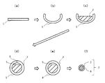
- FIG. 1 shows a schematic diagram of a seamless wire manufacturing method.
- the steel strip 1 is prepared (see FIG. 1A), and this is molded into a sheath shape (see FIG. 1B).
- a flux 2 is filled inside the sheath-shaped steel strip 1 (see FIG. 1 (c)), and the seam 3 is formed by joining the edge portions (see FIG. 1 (d)).
- the seamless wire 7 is formed by welding the seam 3 to form the pipe 4 (see FIG. 1 (e)), drawing the wire 4 and reducing the diameter, thereby filling the steel outer skin 6 with the flux 2. It is manufactured (see FIG. 1 (f)).
- the inside of the pipe 4 before the diameter reduction is filled with the flux 2, but there is a space portion 5 inside as shown in FIG.
- the space part 5 reduces with the diameter reduction by wire drawing, and the space part 5 is substantially lose
- the present inventors have found that in the case of seamless wire production, air flows in the direction opposite to the wire traveling direction, that is, backflow air is generated in the process of diameter reduction. As a result of the disturbance of the flux inside the steel outer sheath due to the backflow air, it was found that the variation in the flux cross-sectional area occupying the wire cross-sectional area becomes large, causing wire breakage.
- Patent Document 1 no consideration is given to a problem unique to seamless wires, such as variations in the cross-sectional area of the flux occupying the cross-sectional area of the wire due to the backflow air generated in the diameter reduction process, and the wire breakage suppressing effect is not considered at all. Are considered limited.
- the present invention provides a flux-filled seamless wire for welding in which variation in the cross-sectional area of the flux occupying the cross-sectional area of the wire due to the backflow air generated in the diameter reduction process is suppressed, and the occurrence of disconnection in the process of warping is prevented.
- the purpose is to do.
- the present inventors In order to reduce the backflow air generated during the diameter reduction process, the present inventors have made intensive studies to achieve the above object, and to reduce as much as possible the space not filled with flux inside the steel outer shell. It was investigated. Specifically, by increasing the Fe content relative to the flux normally used for the wire, the area occupied by the flux with respect to the wire cross-sectional area is increased, and the space not filled with the flux is reduced. The inventors have come to the idea of reducing the amount of the above and have completed the present invention.
- the present invention is a seamless flux-cored wire for welding formed by filling a steel outer shell with flux,
- the amount of Fe in the flux per total mass of the wire is 2 to 15% by mass,
- the flux filling rate is 10-30% by mass,
- the Fe amount (% by mass) in the flux per the total mass of the wire is X and the flux filling rate (%) is Y, the following formula (1) Y> -2X + 19 (1)
- the present invention relates to a flux-cored seamless wire for welding that satisfies the above relationship.
- the above-mentioned welding flux-cored seamless wire may have an outer diameter of 0.8 mm or more and 8.0 mm or less.
- the ratio t / D between the thickness t (mm) of the steel sheath of the wire and the diameter D (mm) of the wire is 0.15 to 0.30. Also good.
- the flux occupying the wire cross section is increased by increasing the flux filling rate while increasing the content of Fe in the flux and making the ratio of components other than Fe and Fe in the total mass of the wire the same.
- the cross-sectional area was increased to reduce the space inside the pipe before diameter reduction. Thereby, the amount of backflow air in the subsequent diameter reduction process is reduced, and variation in the flux cross-sectional area occupying the wire cross section is suppressed.
- Fe has a relatively high specific gravity among the components that can be contained in the flux.
- the flux since the Fe content in the flux is large and the specific gravity of the flux itself is increased, the flux is less susceptible to the influence of backflow air generated in the diameter reduction process, and the flux cross-sectional area occupying the wire cross-section. Variation is further suppressed. In this way, it is possible to effectively prevent disconnection in the diameter reduction process by suppressing variations in the flux cross-sectional area in the wire cross-section caused by the backflow air.
- FIG. 1 is a schematic view of a method for producing a flux-filled seamless wire for welding.
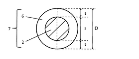
- FIG. 2 is a cross-sectional view of a flux-filled seamless wire for welding.
- the seamless flux-cored wire for welding is a seamless flux-cored wire for welding formed by filling a steel outer shell with flux,
- the amount of Fe in the flux per total mass of the wire is 2 to 15% by mass,
- the flux filling rate is 10-30% by mass,
- the Fe amount (mass%) in the flux per the total mass of the wire is X and the flux filling ratio (mass%) is Y, the following formula (1) Y> -2X + 19 (1) Satisfies the relationship.
- the amount of Fe in the flux per total mass of the wire is 2 to 15% by mass. Since Fe is a component having a relatively high specific gravity among components that can be contained in the flux, the specific gravity of the flux itself is increased as the amount of Fe in the flux increases. As a result, the flux is not easily affected by the backflow air generated in the diameter reduction process, so that variation in the flux cross-sectional area in the wire cross section is suppressed, and disconnection in the diameter reduction process is prevented. In order to sufficiently obtain this effect, in the seamless wire of the present embodiment, the amount of Fe in the flux per the total mass of the wire is 2% by mass or more, preferably 2.5% by mass or more, more preferably 3% by mass or more.
- the specific gravity of Fe is 7.8, and the specific gravity of some of the other components that can be contained in the flux is, for example, Ti specific gravity of 4.5 and Al specific gravity of 2. 7.
- the specific gravity of Mn is 7.4 and the specific gravity of Ni is 8.9.
- the amount of Fe in the flux per the total mass of the wire is 15% by mass or less, preferably 14% by mass or less, more preferably 13% by mass or less.
- the total wire mass is the sum of the total mass of the steel outer sheath and the total mass of the flux.
- Fe in the flux includes not only Fe contained in the flux but also Fe in an alloy component containing Fe, such as Fe—Si and Fe—Mn. To do.
- the seamless wire of the present embodiment is of any kind such as a rutile flux-cored wire, a metal flux-cored wire, a fluoride flux-cored wire, etc. It may be a wire, and other component compositions are not particularly limited, and can be appropriately selected as long as the effects of the present invention are not impaired.
- the components that can be contained in the flux-cored wire according to one aspect are exemplified below, but the components that can be contained and their contents are limited to the following. Is not to be done.
- the following amount of each component is a content in terms of mass% with respect to the total mass of the wire.
- oxides such as TiO 2 , SiO 2 , ZrO 2 , Al 2 O 3 , Na 2 O, and K 2 O are main components of the slag agent and the arc stabilizer.
- the oxide content is preferably 2% or more, and more preferably 3% or more.
- the oxide content is preferably 8% or less, and more preferably 7% or less.
- deoxidation elements such as C, Si, Mn, Al, Mg, Ti, and B are improved in strength and toughness of the weld metal by a deoxidation effect and a refinement effect of the weld metal structure.
- the content of the deoxidizing element is preferably 1% or more, and more preferably 2% or more.
- the toughness of the weld metal may decrease due to excessive strength and hardenability.
- the content of the deoxidizing element is preferably 5% or less, and more preferably 4% or less.
- these deoxidation elements are added from a metal, an alloy, a steel outer shell, etc., and the added form is not particularly limited. Also, values specified for these deoxidizing element shall not include Ti or the like contained in the oxide, such as the TiO 2.
- alloy elements such as Ni, Cu, Cr, Mg, and Co are effective elements for improving strength and toughness, and are appropriately added according to required strength and toughness.
- the content of the alloy element is preferably 10% or less, and more preferably 9% or less.
- these alloy elements are added from a metal, an alloy, a steel outer shell, or the like, and the form of addition is not particularly limited.
- the fluorine compound is a compound having an effect of reducing the H partial pressure in the arc atmosphere and reducing the amount of diffusible hydrogen in the weld metal. It is also a compound that increases fume generated during welding.
- the fluorine compound include NaF, K 2 SiF 6 , LiF, CaF, BaF 2 , and MgF 2 . If content of a fluorine compound is 0.01% or more in total of a fluorine conversion value, the amount of diffusible hydrogen of a weld metal will fall. The content of the fluorine compound is more preferably 0.05% or more in terms of the total fluorine conversion value. On the other hand, when the content of the fluorine compound exceeds 0.50% in terms of the total fluorine conversion value, the amount of fume becomes excessive, so 0.50% or less is preferable, and 0.40% or less is more preferable.
- the balance of the flux-cored wire according to one aspect is Fe and inevitable impurities.
- the flux in the seamless wire of the present embodiment may contain a lubricant such as mica and talc, but from the viewpoint of suppressing an increase in the amount of moisture in the flux, it should contain substantially no lubricant. Is preferred. Moreover, when it does not contain a lubricant substantially, a sintering process can be skipped and it is advantageous also at the point which can suppress manufacturing cost. Note that “substantially does not contain a lubricant” means that the inclusion of a small amount of a lubricant of 0.01% by mass or less per total mass of the flux is permitted. The seamless wire of this embodiment can effectively prevent disconnection even if the flux does not substantially contain a lubricant.
- the flux filling rate in the seamless wire of the present embodiment varies depending on the amount of Fe in the flux per the total mass of the wire in consideration of the component ratio that the wire defined by a predetermined standard should satisfy, but in this embodiment Has a flux filling rate of 10 to 30% by mass.
- the space inside the pipe before the diameter reduction is small.
- variation in a flux cross-sectional area will be suppressed, the performance of the obtained weld metal will be stabilized.
- the flux filling rate is 10% by mass or more, preferably 12% by mass or more, and more preferably 13.5% by mass or more.
- the flux filling rate is 30% by mass or less, preferably 28% by mass or less, and more preferably 25% by mass or less.
- the flux filling rate is defined by the ratio of the flux filled inside the steel outer shell as a ratio to the total mass of the wire (steel outer shell + flux).
- a seamless wire that satisfies the above formula (1) can effectively prevent disconnection in the diameter reduction process due to wire drawing.
- composition of the steel outer sheath in the seamless wire of the present embodiment may be appropriately adjusted in consideration of the proportion of each component such as Fe in the flux, and is not particularly limited as long as the effect of the present invention is exhibited. Typically, it contains additional elements depending on the desired properties, with the balance being Fe and inevitable impurities. Examples of the additive element include C, Si, Mn, P, S, Ni, and Mo.
- the outer diameter of the seamless wire of the present embodiment is not particularly limited, but is preferably 0.8 mm or more, more preferably 1.0 mm or more from the viewpoint of preventing disconnection. Moreover, from a viewpoint of preventing the dispersion
- the ratio t / D between the thickness t (mm) of the steel sheath of the wire and the diameter D (mm) of the wire is 0.15 to 0.30. preferable.
- t / D increases, the flux cross-sectional variation in the wire cross section can be further reduced.
- t / D is preferably 0.15 or more, and more preferably 0.17 or more.
- t / D is 0.30 or less. It is preferable that it is 0.28 or less.
- FIG. 2 is sectional drawing of the seamless wire of this embodiment.
- D is the diameter of the seamless wire 7
- t is the length corresponding to each of the two regions at both ends of the steel outer skin 6 in the diameter D of the seamless wire 7. That is, if the length corresponding to the region occupied by the flux 2 in the diameter of the wire is s, t is a length corresponding to (D ⁇ s) / 2.
- the seamless wire of this embodiment is manufactured by, for example, the manufacturing method shown in FIG.
- a steel strip 1 serving as a steel outer sheath of a seamless wire is prepared.
- the steel strip 1 is formed into a sheath shape.
- the forming method is not particularly limited as long as it is a method capable of forming the steel strip into a sheath shape, and a known forming method can be appropriately applied.
- the flux 2 is filled inside the strip steel 1 formed into a sheath shape.
- the edge portions of the steel strip 1 are put together to form a seam 3, and as shown in FIG. 1 (e), the seam 3 is welded to form a seamless pipe. 4 is formed.
- the space portion 5 inside the pipe 4 in the state shown in FIG.
- strip steel having the same composition as shown in Table 1, having the same plate thickness and the same width was prepared and formed into a sheath shape.
- the balance of the steel strip components shown in Table 1 is Fe and inevitable impurities.
- the edges of the steel strip were brought together and a seam was welded to form a pipe.
- the composition and amount of the flux were adjusted.
- the diameter of the obtained pipe was reduced to 1.170 mm by wire drawing to produce a seamless wire according to each example.
- the component composition of the seamless wire according to each example was within the range shown in Table 2.
- the balance of the wire components shown in Table 2 is Fe and inevitable impurities.
- Table 3 shows the amount of Fe in the flux per wire total mass and the flux filling rate for each example.
- the amount of Fe in the flux per wire total mass was calculated as follows. First, the amount of Fe in the flux filled in the wire was measured by ICP-MS (inductively coupled plasma mass spectrometer, manufactured by SIMADZU: ICP9820). The amount of Fe in the flux per total mass of the wire was calculated by multiplying the amount of Fe in the obtained flux by (flux filling rate / 100).
- the thickness (t, unit: mm) of the steel outer sheath of the wire and the diameter (D, unit: mm) of the wire are measured, and the ratio (t / D) thereof is calculated to obtain a table. This is shown together with 3.
- Table 3 shows the presence or absence of disconnection in the diameter reduction process per ton of wire for each example.
- count of disconnection was zero was evaluated as (circle), and the case where the frequency
- No. 1-No. 8; 1-No. 2 and no. 4 to No. 6 is an example.
- no. 7 and no. 8 is a comparative example.
- the amount of Fe in the flux per total mass of the wire is as low as 1.4% by mass and No. 1 does not satisfy the relationship of the formula (1).
- the amount of Fe in the flux per total mass of the wire is as high as 16.0% by mass.
- the seamless wire No. 7 breakage occurred during the diameter reduction process.
- No. The seamless wire of No. 7 also had a low t / D value of 0.146.
- the flux filling rate is as low as 9.5% by mass.
- No. The seamless wire of 8 had a high t / D value of 0.330.
- no. 1-No. 2 and no. 4 to No. In the seamless wire of No. 6, no disconnection occurred during the diameter reduction process.
Landscapes
- Engineering & Computer Science (AREA)
- Mechanical Engineering (AREA)
- Chemical & Material Sciences (AREA)
- Materials Engineering (AREA)
- Metallurgy (AREA)
- Organic Chemistry (AREA)
- Nonmetallic Welding Materials (AREA)
Abstract
L'invention concerne un fil sans soudure contenant du flux de soudure qui est formé par remplissage d'une gaine d'acier avec un flux, la quantité de Fe dans le flux par masse totale du fil étant de 2 à 15 % en masse, et le rapport de remplissage de flux étant de 10 à 30 % en masse. Quand la quantité (% en masse) de Fe dans le flux par masse totale du fil est X et que le rapport de remplissage de flux (% en masse) est Y, l'expression (1) est satisfaite. Au moyen de ce fil sans soudure contenant du flux de soudure, une variation de la surface de section transversale de flux par rapport à la surface de section transversale du fil, qui est provoquée par un flux d'air inverse généré au cours d'une étape de réduction de diamètre, est réduite, et une rupture de fil au cours de l'étape de réduction de diamètre est empêchée. Y > −2X + 19 (1)
Priority Applications (4)
| Application Number | Priority Date | Filing Date | Title |
|---|---|---|---|
| KR1020197005985A KR102161966B1 (ko) | 2016-08-30 | 2017-08-24 | 용접용 플럭스 코어드 시임리스 와이어 |
| CN201780044436.2A CN109475985A (zh) | 2016-08-30 | 2017-08-24 | 焊接用无缝药芯焊丝 |
| EP17846273.5A EP3508302A4 (fr) | 2016-08-30 | 2017-08-24 | Fil sans soudure contenant du flux de soudure |
| US16/315,785 US20190299340A1 (en) | 2016-08-30 | 2017-08-24 | Seamless flux-cored welding wire |
Applications Claiming Priority (2)
| Application Number | Priority Date | Filing Date | Title |
|---|---|---|---|
| JP2016168202A JP6765259B2 (ja) | 2016-08-30 | 2016-08-30 | 溶接用フラックス入りシームレスワイヤ |
| JP2016-168202 | 2016-08-30 |
Publications (1)
| Publication Number | Publication Date |
|---|---|
| WO2018043268A1 true WO2018043268A1 (fr) | 2018-03-08 |
Family
ID=61305335
Family Applications (1)
| Application Number | Title | Priority Date | Filing Date |
|---|---|---|---|
| PCT/JP2017/030260 Ceased WO2018043268A1 (fr) | 2016-08-30 | 2017-08-24 | Fil sans soudure contenant du flux de soudure |
Country Status (6)
| Country | Link |
|---|---|
| US (1) | US20190299340A1 (fr) |
| EP (1) | EP3508302A4 (fr) |
| JP (1) | JP6765259B2 (fr) |
| KR (1) | KR102161966B1 (fr) |
| CN (1) | CN109475985A (fr) |
| WO (1) | WO2018043268A1 (fr) |
Citations (8)
| Publication number | Priority date | Publication date | Assignee | Title |
|---|---|---|---|---|
| JPS5916694A (ja) * | 1982-07-19 | 1984-01-27 | Nippon Steel Weld Prod & Eng Co Ltd | 溶接用フラックス入りワイヤ |
| JPH08290296A (ja) | 1995-04-20 | 1996-11-05 | Nippon Steel Weld Prod & Eng Co Ltd | 溶接用フラックス入りシームレスワイヤの製造方法 |
| JPH10166180A (ja) * | 1996-12-11 | 1998-06-23 | Nippon Steel Corp | ステンレス鋼溶接用シームレスフラックス入りワイヤの製造方法 |
| JPH1110391A (ja) * | 1997-06-26 | 1999-01-19 | Nippon Steel Corp | 極厚鋼用多電極立向エレクトロガスアーク溶接用フラックス入りワイヤ |
| JPH11129092A (ja) * | 1997-10-29 | 1999-05-18 | Nippon Steel Weld Prod & Eng Co Ltd | ガスシールドアーク溶接用フラックス入りワイヤ |
| JP2000301381A (ja) * | 1999-04-23 | 2000-10-31 | Nippon Steel Weld Prod & Eng Co Ltd | ガスシールドアーク溶接用フラックス入りワイヤ |
| JP2002210588A (ja) * | 2001-01-09 | 2002-07-30 | Kisswell:Kk | ガスシールドアーク溶接用フラックス入りワイヤ |
| JP2016168202A (ja) | 2015-03-13 | 2016-09-23 | ユカイ工学株式会社 | 自動式形象玩具 |
Family Cites Families (6)
| Publication number | Priority date | Publication date | Assignee | Title |
|---|---|---|---|---|
| JP3586362B2 (ja) * | 1997-08-22 | 2004-11-10 | 株式会社神戸製鋼所 | ガスシールドアーク溶接用フラックス入りワイヤ |
| JP2001179481A (ja) * | 1999-12-17 | 2001-07-03 | Nippon Steel Weld Prod & Eng Co Ltd | アーク溶接用フラックス入りワイヤおよびその製造方法 |
| JP2001334392A (ja) * | 2000-05-24 | 2001-12-04 | Nippon Steel Corp | 低温鋼溶接用Ni基合金フラックス入りワイヤ |
| JP5205115B2 (ja) * | 2008-04-16 | 2013-06-05 | 株式会社神戸製鋼所 | 純Arシールドガス溶接用MIGフラックス入りワイヤ及びMIGアーク溶接方法 |
| KR101616237B1 (ko) * | 2013-01-31 | 2016-04-27 | 신닛테츠스미킨 카부시키카이샤 | 플럭스 코어드 와이어, 플럭스 코어드 와이어를 사용한 용접 방법, 플럭스 코어드 와이어를 사용한 용접 조인트의 제조 방법 및 용접 조인트 |
| CN104526188B (zh) * | 2014-12-24 | 2017-01-04 | 洛阳双瑞特种合金材料有限公司 | 一种可焊后消应力热处理的无缝药芯焊丝 |
-
2016
- 2016-08-30 JP JP2016168202A patent/JP6765259B2/ja not_active Expired - Fee Related
-
2017
- 2017-08-24 CN CN201780044436.2A patent/CN109475985A/zh active Pending
- 2017-08-24 US US16/315,785 patent/US20190299340A1/en not_active Abandoned
- 2017-08-24 WO PCT/JP2017/030260 patent/WO2018043268A1/fr not_active Ceased
- 2017-08-24 KR KR1020197005985A patent/KR102161966B1/ko not_active Expired - Fee Related
- 2017-08-24 EP EP17846273.5A patent/EP3508302A4/fr not_active Withdrawn
Patent Citations (8)
| Publication number | Priority date | Publication date | Assignee | Title |
|---|---|---|---|---|
| JPS5916694A (ja) * | 1982-07-19 | 1984-01-27 | Nippon Steel Weld Prod & Eng Co Ltd | 溶接用フラックス入りワイヤ |
| JPH08290296A (ja) | 1995-04-20 | 1996-11-05 | Nippon Steel Weld Prod & Eng Co Ltd | 溶接用フラックス入りシームレスワイヤの製造方法 |
| JPH10166180A (ja) * | 1996-12-11 | 1998-06-23 | Nippon Steel Corp | ステンレス鋼溶接用シームレスフラックス入りワイヤの製造方法 |
| JPH1110391A (ja) * | 1997-06-26 | 1999-01-19 | Nippon Steel Corp | 極厚鋼用多電極立向エレクトロガスアーク溶接用フラックス入りワイヤ |
| JPH11129092A (ja) * | 1997-10-29 | 1999-05-18 | Nippon Steel Weld Prod & Eng Co Ltd | ガスシールドアーク溶接用フラックス入りワイヤ |
| JP2000301381A (ja) * | 1999-04-23 | 2000-10-31 | Nippon Steel Weld Prod & Eng Co Ltd | ガスシールドアーク溶接用フラックス入りワイヤ |
| JP2002210588A (ja) * | 2001-01-09 | 2002-07-30 | Kisswell:Kk | ガスシールドアーク溶接用フラックス入りワイヤ |
| JP2016168202A (ja) | 2015-03-13 | 2016-09-23 | ユカイ工学株式会社 | 自動式形象玩具 |
Non-Patent Citations (1)
| Title |
|---|
| See also references of EP3508302A4 * |
Also Published As
| Publication number | Publication date |
|---|---|
| KR20190035817A (ko) | 2019-04-03 |
| US20190299340A1 (en) | 2019-10-03 |
| EP3508302A4 (fr) | 2020-02-19 |
| EP3508302A1 (fr) | 2019-07-10 |
| JP2018034175A (ja) | 2018-03-08 |
| KR102161966B1 (ko) | 2020-10-06 |
| JP6765259B2 (ja) | 2020-10-07 |
| CN109475985A (zh) | 2019-03-15 |
Similar Documents
| Publication | Publication Date | Title |
|---|---|---|
| JP4995888B2 (ja) | ステンレス鋼アーク溶接フラックス入りワイヤ | |
| US11136654B2 (en) | Low-manganese gas-shielded flux cored welding electrodes | |
| EP2868425B1 (fr) | Fil à flux incorporé en alliage à base de Ni | |
| JP5138242B2 (ja) | 二相ステンレス鋼溶接用フラックス入りワイヤ | |
| JP5242665B2 (ja) | ガスシールドアーク溶接用フラックス入りワイヤ | |
| JP6188621B2 (ja) | 炭酸ガスシールドアーク溶接用フラックス入りワイヤ | |
| JP5236309B2 (ja) | ガスシールドアーク溶接用フラックス入りワイヤ | |
| JP2013158777A (ja) | ガスシールドアーク溶接用フラックス入りワイヤ | |
| JP2003019595A (ja) | 低合金耐熱鋼用ガスシールドアーク溶接用フラックス入りワイヤ | |
| JP6502887B2 (ja) | ガスシールドアーク溶接用フラックス入りワイヤ | |
| CN106794559B (zh) | 气体保护电弧焊用药芯焊丝 | |
| JP6017406B2 (ja) | セルフシールドアーク溶接用ステンレス鋼フラックス入りワイヤ | |
| KR20210136121A (ko) | Ni기 합금 플럭스 코어드 와이어 | |
| JP2014193472A (ja) | ガスシールドアーク溶接用フラックス入りワイヤ | |
| JP6599807B2 (ja) | 炭酸ガスシールドアーク溶接用フラックス入りワイヤ | |
| WO2014054369A1 (fr) | Fil fourré | |
| CN110153593A (zh) | 气体保护电弧焊用药芯焊丝 | |
| JP6988324B2 (ja) | ガスシールドアーク溶接用フラックス入りワイヤ、及び溶接継手の製造方法 | |
| WO2018043268A1 (fr) | Fil sans soudure contenant du flux de soudure | |
| JP2015205304A (ja) | ガスシールドアーク溶接用フラックス入りワイヤ | |
| JP2019171473A (ja) | フラックス入りワイヤ | |
| JP5419492B2 (ja) | ガスシールドアーク溶接用フラックス入りワイヤ | |
| JP6786431B2 (ja) | 炭酸ガスシールドアーク溶接用メタル系フラックス入りワイヤ | |
| JP4560418B2 (ja) | ガスシールドアーク溶接用フラックス入りワイヤ | |
| JP5457301B2 (ja) | ガスシールドアーク溶接用フラックス入りワイヤ |
Legal Events
| Date | Code | Title | Description |
|---|---|---|---|
| 121 | Ep: the epo has been informed by wipo that ep was designated in this application |
Ref document number: 17846273 Country of ref document: EP Kind code of ref document: A1 |
|
| ENP | Entry into the national phase |
Ref document number: 20197005985 Country of ref document: KR Kind code of ref document: A |
|
| NENP | Non-entry into the national phase |
Ref country code: DE |
|
| ENP | Entry into the national phase |
Ref document number: 2017846273 Country of ref document: EP Effective date: 20190401 |