WO2018043268A1 - 溶接用フラックス入りシームレスワイヤ - Google Patents
溶接用フラックス入りシームレスワイヤ Download PDFInfo
- Publication number
- WO2018043268A1 WO2018043268A1 PCT/JP2017/030260 JP2017030260W WO2018043268A1 WO 2018043268 A1 WO2018043268 A1 WO 2018043268A1 JP 2017030260 W JP2017030260 W JP 2017030260W WO 2018043268 A1 WO2018043268 A1 WO 2018043268A1
- Authority
- WO
- WIPO (PCT)
- Prior art keywords
- flux
- wire
- mass
- seamless
- amount
- Prior art date
- Legal status (The legal status is an assumption and is not a legal conclusion. Google has not performed a legal analysis and makes no representation as to the accuracy of the status listed.)
- Ceased
Links
Images
Classifications
-
- B—PERFORMING OPERATIONS; TRANSPORTING
- B23—MACHINE TOOLS; METAL-WORKING NOT OTHERWISE PROVIDED FOR
- B23K—SOLDERING OR UNSOLDERING; WELDING; CLADDING OR PLATING BY SOLDERING OR WELDING; CUTTING BY APPLYING HEAT LOCALLY, e.g. FLAME CUTTING; WORKING BY LASER BEAM
- B23K35/00—Rods, electrodes, materials, or media, for use in soldering, welding, or cutting
- B23K35/22—Rods, electrodes, materials, or media, for use in soldering, welding, or cutting characterised by the composition or nature of the material
- B23K35/36—Selection of non-metallic compositions, e.g. coatings or fluxes; Selection of soldering or welding materials, conjoint with selection of non-metallic compositions, both selections being of interest
- B23K35/368—Selection of non-metallic compositions of core materials either alone or conjoint with selection of soldering or welding materials
-
- B—PERFORMING OPERATIONS; TRANSPORTING
- B23—MACHINE TOOLS; METAL-WORKING NOT OTHERWISE PROVIDED FOR
- B23K—SOLDERING OR UNSOLDERING; WELDING; CLADDING OR PLATING BY SOLDERING OR WELDING; CUTTING BY APPLYING HEAT LOCALLY, e.g. FLAME CUTTING; WORKING BY LASER BEAM
- B23K35/00—Rods, electrodes, materials, or media, for use in soldering, welding, or cutting
- B23K35/02—Rods, electrodes, materials, or media, for use in soldering, welding, or cutting characterised by mechanical features, e.g. shape
- B23K35/0255—Rods, electrodes, materials, or media, for use in soldering, welding, or cutting characterised by mechanical features, e.g. shape for use in welding
- B23K35/0261—Rods, electrodes or wires
- B23K35/0266—Rods, electrodes or wires flux-cored
-
- B—PERFORMING OPERATIONS; TRANSPORTING
- B23—MACHINE TOOLS; METAL-WORKING NOT OTHERWISE PROVIDED FOR
- B23K—SOLDERING OR UNSOLDERING; WELDING; CLADDING OR PLATING BY SOLDERING OR WELDING; CUTTING BY APPLYING HEAT LOCALLY, e.g. FLAME CUTTING; WORKING BY LASER BEAM
- B23K35/00—Rods, electrodes, materials, or media, for use in soldering, welding, or cutting
- B23K35/02—Rods, electrodes, materials, or media, for use in soldering, welding, or cutting characterised by mechanical features, e.g. shape
- B23K35/0222—Rods, electrodes, materials, or media, for use in soldering, welding, or cutting characterised by mechanical features, e.g. shape for use in soldering or brazing
- B23K35/0227—Rods or wires
-
- B—PERFORMING OPERATIONS; TRANSPORTING
- B23—MACHINE TOOLS; METAL-WORKING NOT OTHERWISE PROVIDED FOR
- B23K—SOLDERING OR UNSOLDERING; WELDING; CLADDING OR PLATING BY SOLDERING OR WELDING; CUTTING BY APPLYING HEAT LOCALLY, e.g. FLAME CUTTING; WORKING BY LASER BEAM
- B23K35/00—Rods, electrodes, materials, or media, for use in soldering, welding, or cutting
- B23K35/02—Rods, electrodes, materials, or media, for use in soldering, welding, or cutting characterised by mechanical features, e.g. shape
- B23K35/0255—Rods, electrodes, materials, or media, for use in soldering, welding, or cutting characterised by mechanical features, e.g. shape for use in welding
- B23K35/0261—Rods, electrodes or wires
-
- B—PERFORMING OPERATIONS; TRANSPORTING
- B23—MACHINE TOOLS; METAL-WORKING NOT OTHERWISE PROVIDED FOR
- B23K—SOLDERING OR UNSOLDERING; WELDING; CLADDING OR PLATING BY SOLDERING OR WELDING; CUTTING BY APPLYING HEAT LOCALLY, e.g. FLAME CUTTING; WORKING BY LASER BEAM
- B23K35/00—Rods, electrodes, materials, or media, for use in soldering, welding, or cutting
- B23K35/22—Rods, electrodes, materials, or media, for use in soldering, welding, or cutting characterised by the composition or nature of the material
- B23K35/24—Selection of soldering or welding materials proper
- B23K35/30—Selection of soldering or welding materials proper with the principal constituent melting at less than 1550°C
-
- B—PERFORMING OPERATIONS; TRANSPORTING
- B23—MACHINE TOOLS; METAL-WORKING NOT OTHERWISE PROVIDED FOR
- B23K—SOLDERING OR UNSOLDERING; WELDING; CLADDING OR PLATING BY SOLDERING OR WELDING; CUTTING BY APPLYING HEAT LOCALLY, e.g. FLAME CUTTING; WORKING BY LASER BEAM
- B23K35/00—Rods, electrodes, materials, or media, for use in soldering, welding, or cutting
- B23K35/22—Rods, electrodes, materials, or media, for use in soldering, welding, or cutting characterised by the composition or nature of the material
- B23K35/24—Selection of soldering or welding materials proper
- B23K35/30—Selection of soldering or welding materials proper with the principal constituent melting at less than 1550°C
- B23K35/3053—Fe as the principal constituent
- B23K35/3073—Fe as the principal constituent with Mn as next major constituent
-
- B—PERFORMING OPERATIONS; TRANSPORTING
- B23—MACHINE TOOLS; METAL-WORKING NOT OTHERWISE PROVIDED FOR
- B23K—SOLDERING OR UNSOLDERING; WELDING; CLADDING OR PLATING BY SOLDERING OR WELDING; CUTTING BY APPLYING HEAT LOCALLY, e.g. FLAME CUTTING; WORKING BY LASER BEAM
- B23K35/00—Rods, electrodes, materials, or media, for use in soldering, welding, or cutting
- B23K35/22—Rods, electrodes, materials, or media, for use in soldering, welding, or cutting characterised by the composition or nature of the material
- B23K35/24—Selection of soldering or welding materials proper
- B23K35/30—Selection of soldering or welding materials proper with the principal constituent melting at less than 1550°C
- B23K35/3053—Fe as the principal constituent
- B23K35/308—Fe as the principal constituent with Cr as next major constituent
- B23K35/3086—Fe as the principal constituent with Cr as next major constituent containing Ni or Mn
-
- B—PERFORMING OPERATIONS; TRANSPORTING
- B23—MACHINE TOOLS; METAL-WORKING NOT OTHERWISE PROVIDED FOR
- B23K—SOLDERING OR UNSOLDERING; WELDING; CLADDING OR PLATING BY SOLDERING OR WELDING; CUTTING BY APPLYING HEAT LOCALLY, e.g. FLAME CUTTING; WORKING BY LASER BEAM
- B23K35/00—Rods, electrodes, materials, or media, for use in soldering, welding, or cutting
- B23K35/40—Making wire or rods for soldering or welding
- B23K35/406—Filled tubular wire or rods
-
- C—CHEMISTRY; METALLURGY
- C22—METALLURGY; FERROUS OR NON-FERROUS ALLOYS; TREATMENT OF ALLOYS OR NON-FERROUS METALS
- C22C—ALLOYS
- C22C38/00—Ferrous alloys, e.g. steel alloys
- C22C38/02—Ferrous alloys, e.g. steel alloys containing silicon
-
- C—CHEMISTRY; METALLURGY
- C22—METALLURGY; FERROUS OR NON-FERROUS ALLOYS; TREATMENT OF ALLOYS OR NON-FERROUS METALS
- C22C—ALLOYS
- C22C38/00—Ferrous alloys, e.g. steel alloys
- C22C38/04—Ferrous alloys, e.g. steel alloys containing manganese
Definitions
- the present invention relates to a flux-filled seamless wire for welding.
- a seamless wire is generally manufactured by forming a steel strip into a sheath shape, feeding a flux, forming it into a pipe shape, welding the butt portion, and further reducing the diameter to the product diameter.
- the iron powder in a method for producing a flux-filled seamless wire for welding, contains 6 wt% or more of iron powder and 0.03 to 0.20% of the iron powder content, and the particle size of the iron powder is 125 ⁇ m. It is described that by using the following flux, fluidity of the flux can be improved and disconnection during rolling or wire drawing can be prevented.
- flux of flux is made favorable by mix
- Prevention of disconnection at the time of rolling or wire drawing is achieved by suppressing the variation of the irony thickness.
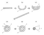
- FIG. 1 shows a schematic diagram of a seamless wire manufacturing method.
- the steel strip 1 is prepared (see FIG. 1A), and this is molded into a sheath shape (see FIG. 1B).
- a flux 2 is filled inside the sheath-shaped steel strip 1 (see FIG. 1 (c)), and the seam 3 is formed by joining the edge portions (see FIG. 1 (d)).
- the seamless wire 7 is formed by welding the seam 3 to form the pipe 4 (see FIG. 1 (e)), drawing the wire 4 and reducing the diameter, thereby filling the steel outer skin 6 with the flux 2. It is manufactured (see FIG. 1 (f)).
- the inside of the pipe 4 before the diameter reduction is filled with the flux 2, but there is a space portion 5 inside as shown in FIG.
- the space part 5 reduces with the diameter reduction by wire drawing, and the space part 5 is substantially lose
- the present inventors have found that in the case of seamless wire production, air flows in the direction opposite to the wire traveling direction, that is, backflow air is generated in the process of diameter reduction. As a result of the disturbance of the flux inside the steel outer sheath due to the backflow air, it was found that the variation in the flux cross-sectional area occupying the wire cross-sectional area becomes large, causing wire breakage.
- Patent Document 1 no consideration is given to a problem unique to seamless wires, such as variations in the cross-sectional area of the flux occupying the cross-sectional area of the wire due to the backflow air generated in the diameter reduction process, and the wire breakage suppressing effect is not considered at all. Are considered limited.
- the present invention provides a flux-filled seamless wire for welding in which variation in the cross-sectional area of the flux occupying the cross-sectional area of the wire due to the backflow air generated in the diameter reduction process is suppressed, and the occurrence of disconnection in the process of warping is prevented.
- the purpose is to do.
- the present inventors In order to reduce the backflow air generated during the diameter reduction process, the present inventors have made intensive studies to achieve the above object, and to reduce as much as possible the space not filled with flux inside the steel outer shell. It was investigated. Specifically, by increasing the Fe content relative to the flux normally used for the wire, the area occupied by the flux with respect to the wire cross-sectional area is increased, and the space not filled with the flux is reduced. The inventors have come to the idea of reducing the amount of the above and have completed the present invention.
- the present invention is a seamless flux-cored wire for welding formed by filling a steel outer shell with flux,
- the amount of Fe in the flux per total mass of the wire is 2 to 15% by mass,
- the flux filling rate is 10-30% by mass,
- the Fe amount (% by mass) in the flux per the total mass of the wire is X and the flux filling rate (%) is Y, the following formula (1) Y> -2X + 19 (1)
- the present invention relates to a flux-cored seamless wire for welding that satisfies the above relationship.
- the above-mentioned welding flux-cored seamless wire may have an outer diameter of 0.8 mm or more and 8.0 mm or less.
- the ratio t / D between the thickness t (mm) of the steel sheath of the wire and the diameter D (mm) of the wire is 0.15 to 0.30. Also good.
- the flux occupying the wire cross section is increased by increasing the flux filling rate while increasing the content of Fe in the flux and making the ratio of components other than Fe and Fe in the total mass of the wire the same.
- the cross-sectional area was increased to reduce the space inside the pipe before diameter reduction. Thereby, the amount of backflow air in the subsequent diameter reduction process is reduced, and variation in the flux cross-sectional area occupying the wire cross section is suppressed.
- Fe has a relatively high specific gravity among the components that can be contained in the flux.
- the flux since the Fe content in the flux is large and the specific gravity of the flux itself is increased, the flux is less susceptible to the influence of backflow air generated in the diameter reduction process, and the flux cross-sectional area occupying the wire cross-section. Variation is further suppressed. In this way, it is possible to effectively prevent disconnection in the diameter reduction process by suppressing variations in the flux cross-sectional area in the wire cross-section caused by the backflow air.
- FIG. 1 is a schematic view of a method for producing a flux-filled seamless wire for welding.
- FIG. 2 is a cross-sectional view of a flux-filled seamless wire for welding.
- the seamless flux-cored wire for welding is a seamless flux-cored wire for welding formed by filling a steel outer shell with flux,
- the amount of Fe in the flux per total mass of the wire is 2 to 15% by mass,
- the flux filling rate is 10-30% by mass,
- the Fe amount (mass%) in the flux per the total mass of the wire is X and the flux filling ratio (mass%) is Y, the following formula (1) Y> -2X + 19 (1) Satisfies the relationship.
- the amount of Fe in the flux per total mass of the wire is 2 to 15% by mass. Since Fe is a component having a relatively high specific gravity among components that can be contained in the flux, the specific gravity of the flux itself is increased as the amount of Fe in the flux increases. As a result, the flux is not easily affected by the backflow air generated in the diameter reduction process, so that variation in the flux cross-sectional area in the wire cross section is suppressed, and disconnection in the diameter reduction process is prevented. In order to sufficiently obtain this effect, in the seamless wire of the present embodiment, the amount of Fe in the flux per the total mass of the wire is 2% by mass or more, preferably 2.5% by mass or more, more preferably 3% by mass or more.
- the specific gravity of Fe is 7.8, and the specific gravity of some of the other components that can be contained in the flux is, for example, Ti specific gravity of 4.5 and Al specific gravity of 2. 7.
- the specific gravity of Mn is 7.4 and the specific gravity of Ni is 8.9.
- the amount of Fe in the flux per the total mass of the wire is 15% by mass or less, preferably 14% by mass or less, more preferably 13% by mass or less.
- the total wire mass is the sum of the total mass of the steel outer sheath and the total mass of the flux.
- Fe in the flux includes not only Fe contained in the flux but also Fe in an alloy component containing Fe, such as Fe—Si and Fe—Mn. To do.
- the seamless wire of the present embodiment is of any kind such as a rutile flux-cored wire, a metal flux-cored wire, a fluoride flux-cored wire, etc. It may be a wire, and other component compositions are not particularly limited, and can be appropriately selected as long as the effects of the present invention are not impaired.
- the components that can be contained in the flux-cored wire according to one aspect are exemplified below, but the components that can be contained and their contents are limited to the following. Is not to be done.
- the following amount of each component is a content in terms of mass% with respect to the total mass of the wire.
- oxides such as TiO 2 , SiO 2 , ZrO 2 , Al 2 O 3 , Na 2 O, and K 2 O are main components of the slag agent and the arc stabilizer.
- the oxide content is preferably 2% or more, and more preferably 3% or more.
- the oxide content is preferably 8% or less, and more preferably 7% or less.
- deoxidation elements such as C, Si, Mn, Al, Mg, Ti, and B are improved in strength and toughness of the weld metal by a deoxidation effect and a refinement effect of the weld metal structure.
- the content of the deoxidizing element is preferably 1% or more, and more preferably 2% or more.
- the toughness of the weld metal may decrease due to excessive strength and hardenability.
- the content of the deoxidizing element is preferably 5% or less, and more preferably 4% or less.
- these deoxidation elements are added from a metal, an alloy, a steel outer shell, etc., and the added form is not particularly limited. Also, values specified for these deoxidizing element shall not include Ti or the like contained in the oxide, such as the TiO 2.
- alloy elements such as Ni, Cu, Cr, Mg, and Co are effective elements for improving strength and toughness, and are appropriately added according to required strength and toughness.
- the content of the alloy element is preferably 10% or less, and more preferably 9% or less.
- these alloy elements are added from a metal, an alloy, a steel outer shell, or the like, and the form of addition is not particularly limited.
- the fluorine compound is a compound having an effect of reducing the H partial pressure in the arc atmosphere and reducing the amount of diffusible hydrogen in the weld metal. It is also a compound that increases fume generated during welding.
- the fluorine compound include NaF, K 2 SiF 6 , LiF, CaF, BaF 2 , and MgF 2 . If content of a fluorine compound is 0.01% or more in total of a fluorine conversion value, the amount of diffusible hydrogen of a weld metal will fall. The content of the fluorine compound is more preferably 0.05% or more in terms of the total fluorine conversion value. On the other hand, when the content of the fluorine compound exceeds 0.50% in terms of the total fluorine conversion value, the amount of fume becomes excessive, so 0.50% or less is preferable, and 0.40% or less is more preferable.
- the balance of the flux-cored wire according to one aspect is Fe and inevitable impurities.
- the flux in the seamless wire of the present embodiment may contain a lubricant such as mica and talc, but from the viewpoint of suppressing an increase in the amount of moisture in the flux, it should contain substantially no lubricant. Is preferred. Moreover, when it does not contain a lubricant substantially, a sintering process can be skipped and it is advantageous also at the point which can suppress manufacturing cost. Note that “substantially does not contain a lubricant” means that the inclusion of a small amount of a lubricant of 0.01% by mass or less per total mass of the flux is permitted. The seamless wire of this embodiment can effectively prevent disconnection even if the flux does not substantially contain a lubricant.
- the flux filling rate in the seamless wire of the present embodiment varies depending on the amount of Fe in the flux per the total mass of the wire in consideration of the component ratio that the wire defined by a predetermined standard should satisfy, but in this embodiment Has a flux filling rate of 10 to 30% by mass.
- the space inside the pipe before the diameter reduction is small.
- variation in a flux cross-sectional area will be suppressed, the performance of the obtained weld metal will be stabilized.
- the flux filling rate is 10% by mass or more, preferably 12% by mass or more, and more preferably 13.5% by mass or more.
- the flux filling rate is 30% by mass or less, preferably 28% by mass or less, and more preferably 25% by mass or less.
- the flux filling rate is defined by the ratio of the flux filled inside the steel outer shell as a ratio to the total mass of the wire (steel outer shell + flux).
- a seamless wire that satisfies the above formula (1) can effectively prevent disconnection in the diameter reduction process due to wire drawing.
- composition of the steel outer sheath in the seamless wire of the present embodiment may be appropriately adjusted in consideration of the proportion of each component such as Fe in the flux, and is not particularly limited as long as the effect of the present invention is exhibited. Typically, it contains additional elements depending on the desired properties, with the balance being Fe and inevitable impurities. Examples of the additive element include C, Si, Mn, P, S, Ni, and Mo.
- the outer diameter of the seamless wire of the present embodiment is not particularly limited, but is preferably 0.8 mm or more, more preferably 1.0 mm or more from the viewpoint of preventing disconnection. Moreover, from a viewpoint of preventing the dispersion
- the ratio t / D between the thickness t (mm) of the steel sheath of the wire and the diameter D (mm) of the wire is 0.15 to 0.30. preferable.
- t / D increases, the flux cross-sectional variation in the wire cross section can be further reduced.
- t / D is preferably 0.15 or more, and more preferably 0.17 or more.
- t / D is 0.30 or less. It is preferable that it is 0.28 or less.
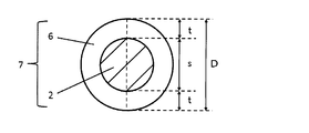
- FIG. 2 is sectional drawing of the seamless wire of this embodiment.
- D is the diameter of the seamless wire 7
- t is the length corresponding to each of the two regions at both ends of the steel outer skin 6 in the diameter D of the seamless wire 7. That is, if the length corresponding to the region occupied by the flux 2 in the diameter of the wire is s, t is a length corresponding to (D ⁇ s) / 2.
- the seamless wire of this embodiment is manufactured by, for example, the manufacturing method shown in FIG.
- a steel strip 1 serving as a steel outer sheath of a seamless wire is prepared.
- the steel strip 1 is formed into a sheath shape.
- the forming method is not particularly limited as long as it is a method capable of forming the steel strip into a sheath shape, and a known forming method can be appropriately applied.
- the flux 2 is filled inside the strip steel 1 formed into a sheath shape.
- the edge portions of the steel strip 1 are put together to form a seam 3, and as shown in FIG. 1 (e), the seam 3 is welded to form a seamless pipe. 4 is formed.
- the space portion 5 inside the pipe 4 in the state shown in FIG.
- strip steel having the same composition as shown in Table 1, having the same plate thickness and the same width was prepared and formed into a sheath shape.
- the balance of the steel strip components shown in Table 1 is Fe and inevitable impurities.
- the edges of the steel strip were brought together and a seam was welded to form a pipe.
- the composition and amount of the flux were adjusted.
- the diameter of the obtained pipe was reduced to 1.170 mm by wire drawing to produce a seamless wire according to each example.
- the component composition of the seamless wire according to each example was within the range shown in Table 2.
- the balance of the wire components shown in Table 2 is Fe and inevitable impurities.
- Table 3 shows the amount of Fe in the flux per wire total mass and the flux filling rate for each example.
- the amount of Fe in the flux per wire total mass was calculated as follows. First, the amount of Fe in the flux filled in the wire was measured by ICP-MS (inductively coupled plasma mass spectrometer, manufactured by SIMADZU: ICP9820). The amount of Fe in the flux per total mass of the wire was calculated by multiplying the amount of Fe in the obtained flux by (flux filling rate / 100).
- the thickness (t, unit: mm) of the steel outer sheath of the wire and the diameter (D, unit: mm) of the wire are measured, and the ratio (t / D) thereof is calculated to obtain a table. This is shown together with 3.
- Table 3 shows the presence or absence of disconnection in the diameter reduction process per ton of wire for each example.
- count of disconnection was zero was evaluated as (circle), and the case where the frequency
- No. 1-No. 8; 1-No. 2 and no. 4 to No. 6 is an example.
- no. 7 and no. 8 is a comparative example.
- the amount of Fe in the flux per total mass of the wire is as low as 1.4% by mass and No. 1 does not satisfy the relationship of the formula (1).
- the amount of Fe in the flux per total mass of the wire is as high as 16.0% by mass.
- the seamless wire No. 7 breakage occurred during the diameter reduction process.
- No. The seamless wire of No. 7 also had a low t / D value of 0.146.
- the flux filling rate is as low as 9.5% by mass.
- No. The seamless wire of 8 had a high t / D value of 0.330.
- no. 1-No. 2 and no. 4 to No. In the seamless wire of No. 6, no disconnection occurred during the diameter reduction process.
Landscapes
- Engineering & Computer Science (AREA)
- Mechanical Engineering (AREA)
- Chemical & Material Sciences (AREA)
- Materials Engineering (AREA)
- Metallurgy (AREA)
- Organic Chemistry (AREA)
- Nonmetallic Welding Materials (AREA)
Abstract
本発明の溶接用フラックス入りシームレスワイヤは、鋼製外皮中にフラックスが充填されてなる溶接用フラックス入りシームレスワイヤであって、ワイヤ全質量あたりの前記フラックス中のFe量が2~15質量%であり、フラックス充填率が10~30質量%であり、ワイヤ全質量あたりの前記フラックス中のFe量(質量%)をXとし、前記フラックス充填率(質量%)をYとしたときに、下記式(1)の関係を満足する。かかる溶接用フラックス入りシームレスワイヤによれば、縮径過程で発生する逆流空気に起因するワイヤ断面積に占めるフラックス断面積のばらつきが抑制され、縮径過程の断線の発生が防止される。 Y>-2X+19 (1)
Description
本発明は、溶接用フラックス入りシームレスワイヤに関する。
従来、造船や海洋構造物等の建造等において溶接用フラックス入りシームレスワイヤ(以下、シームレスワイヤともいう)が用いられている。シームレスワイヤは、一般的に、帯鋼を鞘状に成型し、フラックスを投入した後、パイプ状に成形して突き合わせ部を溶接し、さらに製品径まで縮径を行うことにより製造される。
ここで、圧延または伸線による縮径の過程で断線が発生すると、その回復には相当な時間を要するため、生産歩留まりが著しく低下してしまう。したがって、圧延または伸線工程における断線の発生の防止が求められている。
たとえば、特許文献1では、溶接用フラックス入りシームレスワイヤの製造方法において、6wt%以上の鉄粉及び鉄粉含有量の0.03~0.20%の滑剤を含有し、鉄粉の粒度が125μm以下であるフラックスを用いることにより、フラックスの流動性を改善して、圧延または伸線時の断線を防止できることが記載されている。
ここで、特許文献1では、鉄粉に所定量の滑剤を配合するとともに鉄粉の粒度を所定値以下に規定することでフラックスの流動性を良好にし、管内のフラックスの凹凸に起因する管外皮肉厚の変動を抑制することで、圧延または伸線時の断線の防止が図られている。
図1に、シームレスワイヤの製造方法の概要図を示す。
まず、本製造方法では、帯鋼1を用意し(図1(a)参照)、これを成型して鞘状とする(図1(b)参照)。つづいて、鞘状の帯鋼1の内側にフラックス2を充填し(図1(c)参照)、エッジ部をつきあわせてシーム3を形成する(図1(d)参照)。そして、シーム3を溶接してパイプ4を形成し(図1(e)参照)、これを伸線して縮径することで、鋼製外皮6にフラックス2が充填されてなるシームレスワイヤ7が製造される(図1(f)参照)。
まず、本製造方法では、帯鋼1を用意し(図1(a)参照)、これを成型して鞘状とする(図1(b)参照)。つづいて、鞘状の帯鋼1の内側にフラックス2を充填し(図1(c)参照)、エッジ部をつきあわせてシーム3を形成する(図1(d)参照)。そして、シーム3を溶接してパイプ4を形成し(図1(e)参照)、これを伸線して縮径することで、鋼製外皮6にフラックス2が充填されてなるシームレスワイヤ7が製造される(図1(f)参照)。
ここで、縮径前のパイプ4の内部にはフラックス2が充填されているが、図1(e)に示されるように内部には空間部5が存在する。また、空間部5以外に、粉体からなるフラックス2内にも空隙が存在する。そして、伸線による縮径とともに空間部5は減少していき、最終製品としてのシームレスワイヤ7においては空間部5がほぼ無くなる。
本発明者等は、シームレスワイヤ製造の場合には、縮径の過程において、ワイヤ進行方向と逆方向へ空気が流れていくこと、すなわち、逆流空気が発生することを見出した。そして、この逆流空気によって鋼製外皮内側のフラックスが乱れる結果、ワイヤ断面積に占めるフラックス断面積のばらつきが大きくなり、ワイヤ断線の原因となることをつきとめた。
特許文献1では、このような縮径過程で発生する逆流空気に起因するワイヤ断面積に占めるフラックス断面積のばらつきという、シームレスワイヤ特有の課題については何ら考慮されておらず、ワイヤの断線抑制効果は限定的であると考えられる。
そこで、本発明は、縮径過程で発生する逆流空気に起因するワイヤ断面積に占めるフラックス断面積のばらつきが抑制され、縮経過程の断線の発生が防止された溶接用フラックス入りシームレスワイヤを提供することを目的とする。
本発明者らは、上記目的を達成するために鋭意検討を行い、縮径過程で発生する逆流空気を減少させるために、鋼製外皮内側においてフラックスが充填されていない空間を可能な限り減らすことを検討した。具体的には、ワイヤに通常用いられるフラックスよりもFeの含有量を多くすることにより、ワイヤ断面積に対するフラックスの占有面積を大きくし、フラックスが充填されていない空間を減らすことで、かかる逆流空気の量を減少させることに想到し、本発明を完成するに至った。
すなわち、本発明は、鋼製外皮中にフラックスが充填されてなる溶接用フラックス入りシームレスワイヤであって、
ワイヤ全質量あたりの前記フラックス中のFe量が2~15質量%であり、
フラックス充填率が10~30質量%であり、
ワイヤ全質量あたりの前記フラックス中のFe量(質量%)をXとし、前記フラックス充填率(%)をYとしたときに、下記式(1)
Y>-2X+19 (1)
の関係を満足する溶接用フラックス入りシームレスワイヤに関する。
ワイヤ全質量あたりの前記フラックス中のFe量が2~15質量%であり、
フラックス充填率が10~30質量%であり、
ワイヤ全質量あたりの前記フラックス中のFe量(質量%)をXとし、前記フラックス充填率(%)をYとしたときに、下記式(1)
Y>-2X+19 (1)
の関係を満足する溶接用フラックス入りシームレスワイヤに関する。
上記溶接用フラックス入りシームレスワイヤは、外径が0.8mm以上8.0mm以下であってもよい。
また、上記溶接用フラックス入りシームレスワイヤにおいて、ワイヤにおける鋼製外皮の板厚t(mm)と、ワイヤの直径D(mm)との比t/Dは、0.15~0.30であってもよい。
通常、各ワイヤ成分の比率には制約があるため、鋼製外皮とフラックスの質量比を自由に変更することはできない。そこで、本発明では、フラックス中のFeの含有量を多くして、ワイヤ全質量中のFeとFe以外の成分の比率を同じにしつつ、フラックス充填率を増加させることにより、ワイヤ断面に占めるフラックス断面積を大きくし、縮径前のパイプ内部の空間を減少させた。これにより、その後の縮径過程における逆流空気の量が減少し、ワイヤ断面に占めるフラックス断面積のばらつきが抑制される。また、Feはフラックス中に含有されうる成分の中で、相対的に高比重である。本発明では、フラックス中のFeの含有量が多く、フラックス自体の比重が高められているため、該フラックスは縮径過程で発生する逆流空気の影響を受けにくくなり、ワイヤ断面に占めるフラックス断面積のばらつきがさらに抑制される。このようにして、逆流空気に起因する、ワイヤ断面に占めるフラックス断面積のばらつきを抑制することにより、縮径過程の断線を有効に防止することができる。
以下、本発明を実施するための形態について、詳細に説明する。なお、本発明は、以下に説明する実施形態に限定されるものではない。また、本明細書において、質量を基準とする百分率(質量%)は、重量を基準とする百分率(重量%)と同義である。
本実施形態の溶接用フラックス入りシームレスワイヤは、鋼製外皮中にフラックスが充填されてなる溶接用フラックス入りシームレスワイヤであって、
ワイヤ全質量あたりの前記フラックス中のFe量が2~15質量%であり、
フラックス充填率が10~30質量%であり、
ワイヤ全質量あたりの前記フラックス中のFe量(質量%)をXとし、前記フラックス充填率(質量%)をYとしたときに、下記式(1)
Y>-2X+19 (1)
の関係を満足するものである。
ワイヤ全質量あたりの前記フラックス中のFe量が2~15質量%であり、
フラックス充填率が10~30質量%であり、
ワイヤ全質量あたりの前記フラックス中のFe量(質量%)をXとし、前記フラックス充填率(質量%)をYとしたときに、下記式(1)
Y>-2X+19 (1)
の関係を満足するものである。
本実施形態のシームレスワイヤにおいて、ワイヤ全質量あたりのフラックス中のFe量は2~15質量%である。
Feはフラックス中に含有されうる成分の中で相対的に比重の高い成分であるため、フラックス中のFe量が多いほど、フラックス自体の比重が高められることとなる。その結果、フラックスが縮径過程で発生する逆流空気の影響を受けにくくなるため、ワイヤ断面に占めるフラックス断面積のばらつきが抑制され、縮径過程の断線が防止される。この効果を十分に得るために、本実施形態のシームレスワイヤでは、ワイヤ全質量あたりのフラックス中のFe量を2質量%以上とし、好ましくは2.5質量%以上、より好ましくは3質量%以上とする。なお、Feの比重は7.8であり、また、フラックス中に含有されうるその他の成分のうちのいくつかの成分の比重として、例えば、Tiの比重は4.5、Alの比重は2.7、Mnの比重は7.4、Niの比重は8.9である。
一方、ワイヤ全質量あたりのフラックス中のFe量が15質量%より大きい場合、フラックス充填量が過大となる結果、鋼製外皮の厚みが小さくなり、断線を生じやすくなる。したがって、本実施形態のシームレスワイヤでは、ワイヤ全質量あたりのフラックス中のFe量を15質量%以下、好ましくは14質量%以下、より好ましくは13質量%以下とする。
なお、ワイヤ全質量とは、鋼製外皮の全質量とフラックスの全質量の総和である。
また、本明細書において、フラックス中のFeとは、フラックスに含有されるFe単体に加えて、Fe-SiやFe-Mn等の、Feを含有する合金成分中のFeをも包含するものとする。
Feはフラックス中に含有されうる成分の中で相対的に比重の高い成分であるため、フラックス中のFe量が多いほど、フラックス自体の比重が高められることとなる。その結果、フラックスが縮径過程で発生する逆流空気の影響を受けにくくなるため、ワイヤ断面に占めるフラックス断面積のばらつきが抑制され、縮径過程の断線が防止される。この効果を十分に得るために、本実施形態のシームレスワイヤでは、ワイヤ全質量あたりのフラックス中のFe量を2質量%以上とし、好ましくは2.5質量%以上、より好ましくは3質量%以上とする。なお、Feの比重は7.8であり、また、フラックス中に含有されうるその他の成分のうちのいくつかの成分の比重として、例えば、Tiの比重は4.5、Alの比重は2.7、Mnの比重は7.4、Niの比重は8.9である。
一方、ワイヤ全質量あたりのフラックス中のFe量が15質量%より大きい場合、フラックス充填量が過大となる結果、鋼製外皮の厚みが小さくなり、断線を生じやすくなる。したがって、本実施形態のシームレスワイヤでは、ワイヤ全質量あたりのフラックス中のFe量を15質量%以下、好ましくは14質量%以下、より好ましくは13質量%以下とする。
なお、ワイヤ全質量とは、鋼製外皮の全質量とフラックスの全質量の総和である。
また、本明細書において、フラックス中のFeとは、フラックスに含有されるFe単体に加えて、Fe-SiやFe-Mn等の、Feを含有する合金成分中のFeをも包含するものとする。
本実施形態のシームレスワイヤは、ワイヤ全質量あたりのフラックス中のFe量が上記範囲内であれば、ルチル系フラックス入りワイヤ、メタル系フラックス入りワイヤ、フッ化物系フラックス入りワイヤ等のいずれの種類のワイヤであってもよく、また、その他の成分組成は特に限定されず、本発明の効果を阻害しない限りにおいて、適宜選択できる。
例えば、ある一態様に係るフラックス入りワイヤ(以下、一態様に係るフラックス入りワイヤともいう)に含有されうる成分について、以下に例示するが、含有されうる成分及びそれらの含有量は、以下に限定されるものではない。なお、以下の各成分量は、ワイヤ全質量あたりの質量%表示での含有量である。
一態様に係るフラックス入りワイヤにおいて、TiO2、SiO2、ZrO2、Al2O3、Na2O、K2Oなどの酸化物は、スラグ剤およびアーク安定剤の主成分である。
ここで、酸化物の含有量が少ないと、全姿勢溶接においてビード形成が困難になるとともにアーク安定性が劣化しスパッタ量が増加する。したがって、酸化物の含有量は2%以上であることが好ましく、3%以上であることがより好ましい。一方、酸化物の含有量が多すぎると、スラグ巻込みなどの欠陥が発生しやすくなるとともに、溶接金属中の酸素量が増加してじん性が低下する場合がある。したがって、酸化物の含有量は8%以下であることが好ましく、7%以下であることがより好ましい。
ここで、酸化物の含有量が少ないと、全姿勢溶接においてビード形成が困難になるとともにアーク安定性が劣化しスパッタ量が増加する。したがって、酸化物の含有量は2%以上であることが好ましく、3%以上であることがより好ましい。一方、酸化物の含有量が多すぎると、スラグ巻込みなどの欠陥が発生しやすくなるとともに、溶接金属中の酸素量が増加してじん性が低下する場合がある。したがって、酸化物の含有量は8%以下であることが好ましく、7%以下であることがより好ましい。
一態様に係るフラックス入りワイヤにおいて、C、Si、Mn、Al、Mg、Ti、Bなどの脱酸元素は、脱酸効果ならびに溶接金属組織の微細化効果により溶接金属の強度向上およびじん性向上に有効な元素である。
ここで、脱酸元素の含有量が少ないと、溶接金属の強度が不足したり、じん性が劣化したりする場合がある。したがって、脱酸元素の含有量は1%以上であることが好ましく、2%以上であることがより好ましい。一方、脱酸元素の含有量が多いと強度過多および焼入れ性過多により溶接金属のじん性が低下する場合がある。したがって、脱酸元素の含有量は5%以下であることが好ましく、4%以下であることがより好ましい。
なお、これら脱酸元素は、金属、合金、鋼製外皮などから添加され、その添加される形態は特に限定されるものではない。また、これら脱酸元素について規定する値は上記TiO2などの酸化物に含まれるTi等は含まないものとする。
ここで、脱酸元素の含有量が少ないと、溶接金属の強度が不足したり、じん性が劣化したりする場合がある。したがって、脱酸元素の含有量は1%以上であることが好ましく、2%以上であることがより好ましい。一方、脱酸元素の含有量が多いと強度過多および焼入れ性過多により溶接金属のじん性が低下する場合がある。したがって、脱酸元素の含有量は5%以下であることが好ましく、4%以下であることがより好ましい。
なお、これら脱酸元素は、金属、合金、鋼製外皮などから添加され、その添加される形態は特に限定されるものではない。また、これら脱酸元素について規定する値は上記TiO2などの酸化物に含まれるTi等は含まないものとする。
一態様に係るフラックス入りワイヤにおいて、Ni、Cu、Cr、Mg、Coなどの合金元素は、強度やじん性を向上させるのに有効な元素であり、要求される強度やじん性に応じて適宜添加される。
ここで、合金元素の含有量が多いと焼き入れ性が過剰となり、じん性が劣化したり、低温割れ感受性が高まることにより溶接金属に割れが発生する場合がある。したがって、合金元素の含有量は10%以下であることが好ましく、9%以下であることがより好ましい。
なお、これら合金元素は、金属、合金、鋼製外皮などから添加され、その添加される形態は特に限定されるものではない。
ここで、合金元素の含有量が多いと焼き入れ性が過剰となり、じん性が劣化したり、低温割れ感受性が高まることにより溶接金属に割れが発生する場合がある。したがって、合金元素の含有量は10%以下であることが好ましく、9%以下であることがより好ましい。
なお、これら合金元素は、金属、合金、鋼製外皮などから添加され、その添加される形態は特に限定されるものではない。
一態様に係るフラックス入りワイヤにおいて、フッ素化合物は、アーク雰囲気中のH分圧を下げ、溶接金属の拡散性水素量を低減する効果のある化合物である。また、溶接中に発生するヒュームを増加させる化合物でもある。フッ素化合物は、NaF、K2SiF6、LiF、CaF、BaF2、MgF2などが挙げられる。フッ素化合物の含有量が、フッ素換算値の合計で0.01%以上であれば、溶接金属の拡散性水素量が低下する。フッ素化合物の含有量は、より好ましくはフッ素換算値の合計で0.05%以上である。一方、フッ素化合物の含有量が、フッ素換算値の合計で0.50%を超えるとヒューム量が過剰となるため、0.50%以下が好ましく、0.40%以下がより好ましい。
なお、一態様に係るフラックス入りワイヤの残部は、Fe及び不可避的不純物である。
また、本実施形態のシームレスワイヤにおけるフラックスは、マイカやタルク等の滑剤を含有していてもよいが、フラックス中の水分量の増加を抑制するとの観点からは、滑剤を実質的に含有しないことが好ましい。また、滑剤を実質的に含有しない場合には、焼結工程を省略することができ、製造コストを抑制できる点でも有利である。なお、「滑剤を実質的に含有しない」とは、フラックス全質量あたり、0.01質量%以下の少量の滑剤であれば含有が許容されることを意味する。本実施形態のシームレスワイヤは、フラックスは滑剤を実質的に含有しなくても、断線を有効に防止することができる。
また、本実施形態のシームレスワイヤにおけるフラックス充填率は、所定の規格により定められるワイヤが満足すべき成分比率を考慮すると、ワイヤ全質量あたりのフラックス中のFe量によって変化するが、本実施形態においては、フラックス充填率を10~30質量%とする。ここで、ワイヤの縮径過程で発生する逆流空気を減少させ、ワイヤ断面に占めるフラックス断面積のばらつきを抑制するためには、縮径前のパイプ内部の空間が小さい方が好ましい。また、パイプ内部の空間が小さければ、フラックス断面積のばらつきが抑制されるため、得られる溶着金属の性能が安定する。これらの観点より、本実施形態においては、フラックス充填率を10質量%以上とし、好ましくは12質量%以上とし、より好ましくは13.5質量%以上とする。
一方、フラックス充填率を高くしすぎると、鋼製外皮を過度に薄くせざるを得なくなり、断線の発生を招くおそれがある。したがって、本実施形態では、フラックス充填率を30質量%以下とし、好ましくは28質量%以下とし、より好ましくは25質量%以下とする。
なお、フラックス充填率は、鋼製外皮内側に充填されるフラックスの質量を、ワイヤ(鋼製外皮+フラックス)の全質量に対する割合で規定したものである。
一方、フラックス充填率を高くしすぎると、鋼製外皮を過度に薄くせざるを得なくなり、断線の発生を招くおそれがある。したがって、本実施形態では、フラックス充填率を30質量%以下とし、好ましくは28質量%以下とし、より好ましくは25質量%以下とする。
なお、フラックス充填率は、鋼製外皮内側に充填されるフラックスの質量を、ワイヤ(鋼製外皮+フラックス)の全質量に対する割合で規定したものである。
また、本実施形態のシームレスワイヤにおいては、ワイヤ全質量あたりのフラックス中のFe量(質量%)をXとし、フラックス充填率(質量%)をYとしたときに、下記式(1)を満足する必要がある。
Y>-2X+19 (1)
Y>-2X+19 (1)
後述する実施例において実証されるように、上記式(1)を満足するシームレスワイヤであれば、伸線による縮径過程の断線を有効に防止することができる。
本実施形態のシームレスワイヤにおける鋼製外皮の組成は、フラックス中におけるFe等の各成分割合を考慮して適宜調整すればよく、本発明の効果が奏される限りにおいて特に限定されない。典型的には、所望される特性に応じた添加元素を含有し、残部がFe及び不可避的不純物である。添加元素としては、例えば、C、Si、Mn、P、S、Ni、Mo等が例示される。
本実施形態のシームレスワイヤの外径は、特に限定されるものではないが、断線防止の観点から、好ましくは0.8mm以上であり、より好ましくは1.0mm以上である。また、フラックス充填率のばらつきを防止する観点からは、好ましくは8mm以下であり、より好ましくは6mm以下であり、さらに好ましくは5mm以下である。
また、本実施形態のシームレスワイヤにおいて、ワイヤにおける鋼製外皮の板厚t(mm)と、ワイヤの直径D(mm)との比t/Dは、0.15~0.30であることが好ましい。t/Dが大きくなるほど、ワイヤ断面におけるフラックス断面積のバラつきをより低減することができる。この観点から、t/Dは0.15以上であることが好ましく、0.17以上であることがより好ましい。一方、t/Dが大きくなりすぎると、フラックス断面積が減少し、鋼製外皮の部分が増加しすぎて、ワイヤ送給性が好ましくなくなる場合があるため、t/Dは0.30以下であることが好ましく、0.28以下であることがより好ましい。
なお、ワイヤにおける鋼製外皮の板厚tについて、本実施形態のシームレスワイヤの断面図である図2を参照して説明する。図2において、Dはシームレスワイヤ7の直径であり、tは、シームレスワイヤ7の直径Dにおいて、鋼製外皮6が占める両端の2つの領域のそれぞれに相当する長さである。すなわち、ワイヤの直径において、フラックス2が占める領域に相当する長さをsとすると、tは(D-s)/2に相当する長さである。
本実施形態のシームレスワイヤは、例えば、図1に示される製造方法によって製造される。
まず、図1(a)に示されるように、シームレスワイヤの鋼製外皮となる帯鋼1を用意する。つづいて、図1(b)に示されるように、帯鋼1を鞘状に成形する。成形方法としては、帯鋼を鞘状に成形できる方法であれば特に限定されず、公知の成形方法を適宜適用することができる。
つづいて、図1(c)に示されるように、鞘状に成形された帯鋼1の内側にフラックス2を充填する。その後、図1(d)に示されるように、帯鋼1のエッジ部をつきあわせてシーム3を形成し、さらに図1(e)に示されるように、シーム3を溶接してシームレスのパイプ4を形成する。ここで、本実施形態では、ワイヤ全質量あたりのフラックス中のFe量を増加させてフラックス充填率を増加させることで、図1(e)に示される状態における、パイプ4の内部における空間部5の占める割合を減少させている。
この状態で伸線による縮径を行うと、空間部5は徐々に減少していき、最終的には図1(f)に示されるような、空間部5がほぼ無い、鋼製外皮6内側にフラックス2が充填されてなるシームレスワイヤ7が製造される。ここで、縮径の過程において、空間部5に存在する空気はワイヤ進行方向と逆方向へ流れていき、すなわち、逆流空気が発生する。しかしながら、本実施形態では、パイプ4の内部における空間部5の占める割合を低く抑えているため、逆流空気の量を抑制でき、逆流空気に起因するパイプ4内でのフラックス2の乱れを抑制できる。また、Feを多く含有し、高比重のフラックス2を用いているため、該フラックス2は逆流空気の影響を受けにくい。その結果、ワイヤ断面積に占めるフラックス断面積のばらつきが良好に抑制され、縮径過程でのワイヤの断線が有効に防止される。
以下に、実施例を挙げて本発明をさらに具体的に説明するが、本発明は、これらの実施例に限定されるものではなく、本発明の趣旨に適合し得る範囲で変更を加えて実施することが可能であり、それらはいずれも本発明の技術的範囲に包含される。
まず、表1に示される成分組成を有し、同じ板厚で、同じ幅の帯鋼を用意し、鞘状に成形した。なお、表1に示される帯鋼成分の残部は、Fe及び不可避的不純物である。
つづいて、鞘状の帯鋼にフラックスを投入した後、帯鋼のエッジ部をつきあわせ、シームを溶接してパイプを形成した。なお、各例においては、フラックスの組成および量をそれぞれ調整した。
さらに、得られたパイプを伸線により直径1.170mmまで縮径して、各例に係るシームレスワイヤを作製した。
各例に係るシームレスワイヤの成分組成は、表2に示される範囲内であった。なお、表2に示されるワイヤ成分の残部は、Fe及び不可避的不純物である。
つづいて、鞘状の帯鋼にフラックスを投入した後、帯鋼のエッジ部をつきあわせ、シームを溶接してパイプを形成した。なお、各例においては、フラックスの組成および量をそれぞれ調整した。
さらに、得られたパイプを伸線により直径1.170mmまで縮径して、各例に係るシームレスワイヤを作製した。
各例に係るシームレスワイヤの成分組成は、表2に示される範囲内であった。なお、表2に示されるワイヤ成分の残部は、Fe及び不可避的不純物である。
表3に、各例についての、ワイヤ全質量あたりのフラックス中のFe量及びフラックス充填率を示す。ここで、ワイヤ全質量あたりのフラックス中のFe量は、以下のように算出した。
まず、ワイヤ中に充填されたフラックス中のFe量をICP-MS(誘導結合プラズマ質量分析計、SIMADZU社製:ICP9820)により測定した。得られたフラックス中のFe量に対して、(フラックス充填率/100)を乗じることにより、ワイヤ全質量あたりのフラックス中のFe量を算出した。
まず、ワイヤ中に充填されたフラックス中のFe量をICP-MS(誘導結合プラズマ質量分析計、SIMADZU社製:ICP9820)により測定した。得られたフラックス中のFe量に対して、(フラックス充填率/100)を乗じることにより、ワイヤ全質量あたりのフラックス中のFe量を算出した。
また、ワイヤにおける鋼製外皮の板厚(t、単位:mm)とワイヤの直径(D、単位:mm)とをそれぞれ測定し、また、それらの比(t/D)を算出して、表3にあわせて示した。
また、各例について、ワイヤ全質量あたりの前記フラックス中のFe量(質量%)をXとし、前記フラックス充填率(質量%)をYとしたときの、下記式(1)の右辺の値と、下記式(1)を満たすか否かについて、表3にあわせて示した。
Y>-2X+19 (1)
Y>-2X+19 (1)
また、各例についての、ワイヤ1トンあたりの縮径過程での断線の有無を、表3にあわせて示した。なお、断線回数がゼロであった場合を○、断線回数が1回以上であった場合を×として評価した。


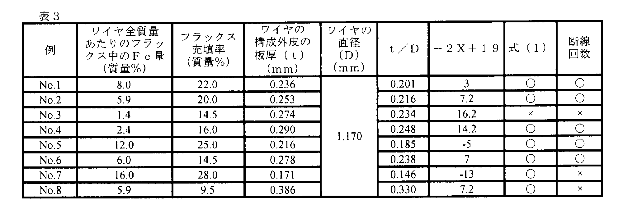
No.1~No.8のうち、No.1~No.2及びNo.4~No.6は実施例であり、No.3、No.7及びNo.8は比較例である。
ワイヤ全質量あたりのフラックス中のFe量が1.4質量%と低く、また式(1)の関係を満たしていないNo.3のシームレスワイヤにおいては、縮径過程で断線が発生した。
また、ワイヤ全質量あたりのフラックス中のFe量が16.0質量%と高いNo.7のシームレスワイヤにおいては、縮径過程で断線が発生した。なお、No.7のシームレスワイヤはt/Dの値も0.146と低かった。
また、フラックス充填率が9.5質量%と低いNo.8のシームレスワイヤにおいても、縮径過程で断線が発生した。なお、No.8のシームレスワイヤはt/Dの値も0.330と高かった。
一方、本発明に規定の範囲内であるNo.1~No.2及びNo.4~No.6のシームレスワイヤにおいては、縮径過程での断線は発生しなかった。
ワイヤ全質量あたりのフラックス中のFe量が1.4質量%と低く、また式(1)の関係を満たしていないNo.3のシームレスワイヤにおいては、縮径過程で断線が発生した。
また、ワイヤ全質量あたりのフラックス中のFe量が16.0質量%と高いNo.7のシームレスワイヤにおいては、縮径過程で断線が発生した。なお、No.7のシームレスワイヤはt/Dの値も0.146と低かった。
また、フラックス充填率が9.5質量%と低いNo.8のシームレスワイヤにおいても、縮径過程で断線が発生した。なお、No.8のシームレスワイヤはt/Dの値も0.330と高かった。
一方、本発明に規定の範囲内であるNo.1~No.2及びNo.4~No.6のシームレスワイヤにおいては、縮径過程での断線は発生しなかった。
本発明を特定の態様を参照して詳細に説明したが、本発明の精神と範囲を離れることなく様々な変更および修正が可能であることは、当業者にとって明らかである。
なお、本出願は、2016年8月30日付けで出願された日本特許出願(特願2016-168202)に基づいており、その全体が引用により援用される。
なお、本出願は、2016年8月30日付けで出願された日本特許出願(特願2016-168202)に基づいており、その全体が引用により援用される。
1 帯鋼
2 フラックス
3 シーム
4 パイプ
5 空間部
6 鋼製外皮
7 シームレスワイヤ
2 フラックス
3 シーム
4 パイプ
5 空間部
6 鋼製外皮
7 シームレスワイヤ
Claims (3)
- 鋼製外皮中にフラックスが充填されてなる溶接用フラックス入りシームレスワイヤであって、
ワイヤ全質量あたりの前記フラックス中のFe量が2~15質量%であり、
フラックス充填率が10~30質量%であり、
ワイヤ全質量あたりの前記フラックス中のFe量(質量%)をXとし、前記フラックス充填率(質量%)をYとしたときに、下記式(1)
Y>-2X+19 (1)
の関係を満足する溶接用フラックス入りシームレスワイヤ。 - 外径が0.8mm以上8.0mm以下である、請求項1に記載の溶接用フラックス入りシームレスワイヤ。
- 前記ワイヤにおける前記鋼製外皮の板厚t(mm)と、前記ワイヤの直径D(mm)との比t/Dが0.15~0.30である請求項1または2に記載の溶接用フラックス入りシームレスワイヤ。
Priority Applications (4)
| Application Number | Priority Date | Filing Date | Title |
|---|---|---|---|
| KR1020197005985A KR102161966B1 (ko) | 2016-08-30 | 2017-08-24 | 용접용 플럭스 코어드 시임리스 와이어 |
| EP17846273.5A EP3508302A4 (en) | 2016-08-30 | 2017-08-24 | SOLDER-FREE WIRE CONTAINING WELDING FLOW |
| US16/315,785 US20190299340A1 (en) | 2016-08-30 | 2017-08-24 | Seamless flux-cored welding wire |
| CN201780044436.2A CN109475985A (zh) | 2016-08-30 | 2017-08-24 | 焊接用无缝药芯焊丝 |
Applications Claiming Priority (2)
| Application Number | Priority Date | Filing Date | Title |
|---|---|---|---|
| JP2016168202A JP6765259B2 (ja) | 2016-08-30 | 2016-08-30 | 溶接用フラックス入りシームレスワイヤ |
| JP2016-168202 | 2016-08-30 |
Publications (1)
| Publication Number | Publication Date |
|---|---|
| WO2018043268A1 true WO2018043268A1 (ja) | 2018-03-08 |
Family
ID=61305335
Family Applications (1)
| Application Number | Title | Priority Date | Filing Date |
|---|---|---|---|
| PCT/JP2017/030260 Ceased WO2018043268A1 (ja) | 2016-08-30 | 2017-08-24 | 溶接用フラックス入りシームレスワイヤ |
Country Status (6)
| Country | Link |
|---|---|
| US (1) | US20190299340A1 (ja) |
| EP (1) | EP3508302A4 (ja) |
| JP (1) | JP6765259B2 (ja) |
| KR (1) | KR102161966B1 (ja) |
| CN (1) | CN109475985A (ja) |
| WO (1) | WO2018043268A1 (ja) |
Citations (8)
| Publication number | Priority date | Publication date | Assignee | Title |
|---|---|---|---|---|
| JPS5916694A (ja) * | 1982-07-19 | 1984-01-27 | Nippon Steel Weld Prod & Eng Co Ltd | 溶接用フラックス入りワイヤ |
| JPH08290296A (ja) | 1995-04-20 | 1996-11-05 | Nippon Steel Weld Prod & Eng Co Ltd | 溶接用フラックス入りシームレスワイヤの製造方法 |
| JPH10166180A (ja) * | 1996-12-11 | 1998-06-23 | Nippon Steel Corp | ステンレス鋼溶接用シームレスフラックス入りワイヤの製造方法 |
| JPH1110391A (ja) * | 1997-06-26 | 1999-01-19 | Nippon Steel Corp | 極厚鋼用多電極立向エレクトロガスアーク溶接用フラックス入りワイヤ |
| JPH11129092A (ja) * | 1997-10-29 | 1999-05-18 | Nippon Steel Weld Prod & Eng Co Ltd | ガスシールドアーク溶接用フラックス入りワイヤ |
| JP2000301381A (ja) * | 1999-04-23 | 2000-10-31 | Nippon Steel Weld Prod & Eng Co Ltd | ガスシールドアーク溶接用フラックス入りワイヤ |
| JP2002210588A (ja) * | 2001-01-09 | 2002-07-30 | Kisswell:Kk | ガスシールドアーク溶接用フラックス入りワイヤ |
| JP2016168202A (ja) | 2015-03-13 | 2016-09-23 | ユカイ工学株式会社 | 自動式形象玩具 |
Family Cites Families (6)
| Publication number | Priority date | Publication date | Assignee | Title |
|---|---|---|---|---|
| JP3586362B2 (ja) * | 1997-08-22 | 2004-11-10 | 株式会社神戸製鋼所 | ガスシールドアーク溶接用フラックス入りワイヤ |
| JP2001179481A (ja) * | 1999-12-17 | 2001-07-03 | Nippon Steel Weld Prod & Eng Co Ltd | アーク溶接用フラックス入りワイヤおよびその製造方法 |
| JP2001334392A (ja) * | 2000-05-24 | 2001-12-04 | Nippon Steel Corp | 低温鋼溶接用Ni基合金フラックス入りワイヤ |
| JP5205115B2 (ja) * | 2008-04-16 | 2013-06-05 | 株式会社神戸製鋼所 | 純Arシールドガス溶接用MIGフラックス入りワイヤ及びMIGアーク溶接方法 |
| WO2014119082A1 (ja) * | 2013-01-31 | 2014-08-07 | 新日鐵住金株式会社 | フラックス入りワイヤ、フラックス入りワイヤを用いた溶接方法、フラックス入りワイヤを用いた溶接継手の製造方法、および溶接継手 |
| CN104526188B (zh) * | 2014-12-24 | 2017-01-04 | 洛阳双瑞特种合金材料有限公司 | 一种可焊后消应力热处理的无缝药芯焊丝 |
-
2016
- 2016-08-30 JP JP2016168202A patent/JP6765259B2/ja not_active Expired - Fee Related
-
2017
- 2017-08-24 CN CN201780044436.2A patent/CN109475985A/zh active Pending
- 2017-08-24 US US16/315,785 patent/US20190299340A1/en not_active Abandoned
- 2017-08-24 KR KR1020197005985A patent/KR102161966B1/ko not_active Expired - Fee Related
- 2017-08-24 EP EP17846273.5A patent/EP3508302A4/en not_active Withdrawn
- 2017-08-24 WO PCT/JP2017/030260 patent/WO2018043268A1/ja not_active Ceased
Patent Citations (8)
| Publication number | Priority date | Publication date | Assignee | Title |
|---|---|---|---|---|
| JPS5916694A (ja) * | 1982-07-19 | 1984-01-27 | Nippon Steel Weld Prod & Eng Co Ltd | 溶接用フラックス入りワイヤ |
| JPH08290296A (ja) | 1995-04-20 | 1996-11-05 | Nippon Steel Weld Prod & Eng Co Ltd | 溶接用フラックス入りシームレスワイヤの製造方法 |
| JPH10166180A (ja) * | 1996-12-11 | 1998-06-23 | Nippon Steel Corp | ステンレス鋼溶接用シームレスフラックス入りワイヤの製造方法 |
| JPH1110391A (ja) * | 1997-06-26 | 1999-01-19 | Nippon Steel Corp | 極厚鋼用多電極立向エレクトロガスアーク溶接用フラックス入りワイヤ |
| JPH11129092A (ja) * | 1997-10-29 | 1999-05-18 | Nippon Steel Weld Prod & Eng Co Ltd | ガスシールドアーク溶接用フラックス入りワイヤ |
| JP2000301381A (ja) * | 1999-04-23 | 2000-10-31 | Nippon Steel Weld Prod & Eng Co Ltd | ガスシールドアーク溶接用フラックス入りワイヤ |
| JP2002210588A (ja) * | 2001-01-09 | 2002-07-30 | Kisswell:Kk | ガスシールドアーク溶接用フラックス入りワイヤ |
| JP2016168202A (ja) | 2015-03-13 | 2016-09-23 | ユカイ工学株式会社 | 自動式形象玩具 |
Non-Patent Citations (1)
| Title |
|---|
| See also references of EP3508302A4 * |
Also Published As
| Publication number | Publication date |
|---|---|
| CN109475985A (zh) | 2019-03-15 |
| JP2018034175A (ja) | 2018-03-08 |
| EP3508302A1 (en) | 2019-07-10 |
| JP6765259B2 (ja) | 2020-10-07 |
| US20190299340A1 (en) | 2019-10-03 |
| KR20190035817A (ko) | 2019-04-03 |
| KR102161966B1 (ko) | 2020-10-06 |
| EP3508302A4 (en) | 2020-02-19 |
Similar Documents
| Publication | Publication Date | Title |
|---|---|---|
| JP4995888B2 (ja) | ステンレス鋼アーク溶接フラックス入りワイヤ | |
| US11136654B2 (en) | Low-manganese gas-shielded flux cored welding electrodes | |
| EP2868425B1 (en) | Ni based alloy flux cored wire | |
| JP5138242B2 (ja) | 二相ステンレス鋼溶接用フラックス入りワイヤ | |
| JP5242665B2 (ja) | ガスシールドアーク溶接用フラックス入りワイヤ | |
| JP6188621B2 (ja) | 炭酸ガスシールドアーク溶接用フラックス入りワイヤ | |
| JP5236309B2 (ja) | ガスシールドアーク溶接用フラックス入りワイヤ | |
| JP2013158777A (ja) | ガスシールドアーク溶接用フラックス入りワイヤ | |
| JP2003019595A (ja) | 低合金耐熱鋼用ガスシールドアーク溶接用フラックス入りワイヤ | |
| JP6502887B2 (ja) | ガスシールドアーク溶接用フラックス入りワイヤ | |
| CN106794559B (zh) | 气体保护电弧焊用药芯焊丝 | |
| JP6017406B2 (ja) | セルフシールドアーク溶接用ステンレス鋼フラックス入りワイヤ | |
| KR20210136121A (ko) | Ni기 합금 플럭스 코어드 와이어 | |
| JP6599807B2 (ja) | 炭酸ガスシールドアーク溶接用フラックス入りワイヤ | |
| WO2014054369A1 (ja) | フラックス入りワイヤ | |
| CN110153593A (zh) | 气体保护电弧焊用药芯焊丝 | |
| JP6988324B2 (ja) | ガスシールドアーク溶接用フラックス入りワイヤ、及び溶接継手の製造方法 | |
| JP2015205304A (ja) | ガスシールドアーク溶接用フラックス入りワイヤ | |
| JP2019171473A (ja) | フラックス入りワイヤ | |
| JP6765259B2 (ja) | 溶接用フラックス入りシームレスワイヤ | |
| JP5419492B2 (ja) | ガスシールドアーク溶接用フラックス入りワイヤ | |
| JP6786431B2 (ja) | 炭酸ガスシールドアーク溶接用メタル系フラックス入りワイヤ | |
| JP4560418B2 (ja) | ガスシールドアーク溶接用フラックス入りワイヤ | |
| JP5457301B2 (ja) | ガスシールドアーク溶接用フラックス入りワイヤ | |
| JP7244399B2 (ja) | ガスシールドアーク溶接用フラックス入りワイヤ |
Legal Events
| Date | Code | Title | Description |
|---|---|---|---|
| 121 | Ep: the epo has been informed by wipo that ep was designated in this application |
Ref document number: 17846273 Country of ref document: EP Kind code of ref document: A1 |
|
| ENP | Entry into the national phase |
Ref document number: 20197005985 Country of ref document: KR Kind code of ref document: A |
|
| NENP | Non-entry into the national phase |
Ref country code: DE |
|
| ENP | Entry into the national phase |
Ref document number: 2017846273 Country of ref document: EP Effective date: 20190401 |