WO2018043443A1 - Électrode de batterie rechargeable, son procédé de fabrication, batterie rechargeable et son procédé de fabrication - Google Patents
Électrode de batterie rechargeable, son procédé de fabrication, batterie rechargeable et son procédé de fabrication Download PDFInfo
- Publication number
- WO2018043443A1 WO2018043443A1 PCT/JP2017/030827 JP2017030827W WO2018043443A1 WO 2018043443 A1 WO2018043443 A1 WO 2018043443A1 JP 2017030827 W JP2017030827 W JP 2017030827W WO 2018043443 A1 WO2018043443 A1 WO 2018043443A1
- Authority
- WO
- WIPO (PCT)
- Prior art keywords
- electrode
- active material
- material layer
- secondary battery
- core
- Prior art date
- Legal status (The legal status is an assumption and is not a legal conclusion. Google has not performed a legal analysis and makes no representation as to the accuracy of the status listed.)
- Ceased
Links
Images




Classifications
-
- H—ELECTRICITY
- H01—ELECTRIC ELEMENTS
- H01M—PROCESSES OR MEANS, e.g. BATTERIES, FOR THE DIRECT CONVERSION OF CHEMICAL ENERGY INTO ELECTRICAL ENERGY
- H01M4/00—Electrodes
- H01M4/02—Electrodes composed of, or comprising, active material
- H01M4/04—Processes of manufacture in general
- H01M4/043—Processes of manufacture in general involving compressing or compaction
-
- B—PERFORMING OPERATIONS; TRANSPORTING
- B23—MACHINE TOOLS; METAL-WORKING NOT OTHERWISE PROVIDED FOR
- B23K—SOLDERING OR UNSOLDERING; WELDING; CLADDING OR PLATING BY SOLDERING OR WELDING; CUTTING BY APPLYING HEAT LOCALLY, e.g. FLAME CUTTING; WORKING BY LASER BEAM
- B23K26/00—Working by laser beam, e.g. welding, cutting or boring
- B23K26/08—Devices involving relative movement between laser beam and workpiece
- B23K26/082—Scanning systems, i.e. devices involving movement of the laser beam relative to the laser head
-
- B—PERFORMING OPERATIONS; TRANSPORTING
- B23—MACHINE TOOLS; METAL-WORKING NOT OTHERWISE PROVIDED FOR
- B23K—SOLDERING OR UNSOLDERING; WELDING; CLADDING OR PLATING BY SOLDERING OR WELDING; CUTTING BY APPLYING HEAT LOCALLY, e.g. FLAME CUTTING; WORKING BY LASER BEAM
- B23K26/00—Working by laser beam, e.g. welding, cutting or boring
- B23K26/08—Devices involving relative movement between laser beam and workpiece
- B23K26/083—Devices involving movement of the workpiece in at least one axial direction
- B23K26/0838—Devices involving movement of the workpiece in at least one axial direction by using an endless conveyor belt
- B23K26/0846—Devices involving movement of the workpiece in at least one axial direction by using an endless conveyor belt for moving elongated workpieces longitudinally, e.g. wire or strip material
-
- B—PERFORMING OPERATIONS; TRANSPORTING
- B23—MACHINE TOOLS; METAL-WORKING NOT OTHERWISE PROVIDED FOR
- B23K—SOLDERING OR UNSOLDERING; WELDING; CLADDING OR PLATING BY SOLDERING OR WELDING; CUTTING BY APPLYING HEAT LOCALLY, e.g. FLAME CUTTING; WORKING BY LASER BEAM
- B23K26/00—Working by laser beam, e.g. welding, cutting or boring
- B23K26/36—Removing material
- B23K26/38—Removing material by boring or cutting
-
- B—PERFORMING OPERATIONS; TRANSPORTING
- B23—MACHINE TOOLS; METAL-WORKING NOT OTHERWISE PROVIDED FOR
- B23K—SOLDERING OR UNSOLDERING; WELDING; CLADDING OR PLATING BY SOLDERING OR WELDING; CUTTING BY APPLYING HEAT LOCALLY, e.g. FLAME CUTTING; WORKING BY LASER BEAM
- B23K26/00—Working by laser beam, e.g. welding, cutting or boring
- B23K26/36—Removing material
- B23K26/40—Removing material taking account of the properties of the material involved
- B23K26/402—Removing material taking account of the properties of the material involved involving non-metallic material, e.g. isolators
-
- H—ELECTRICITY
- H01—ELECTRIC ELEMENTS
- H01M—PROCESSES OR MEANS, e.g. BATTERIES, FOR THE DIRECT CONVERSION OF CHEMICAL ENERGY INTO ELECTRICAL ENERGY
- H01M10/00—Secondary cells; Manufacture thereof
- H01M10/05—Accumulators with non-aqueous electrolyte
- H01M10/052—Li-accumulators
- H01M10/0525—Rocking-chair batteries, i.e. batteries with lithium insertion or intercalation in both electrodes; Lithium-ion batteries
-
- H—ELECTRICITY
- H01—ELECTRIC ELEMENTS
- H01M—PROCESSES OR MEANS, e.g. BATTERIES, FOR THE DIRECT CONVERSION OF CHEMICAL ENERGY INTO ELECTRICAL ENERGY
- H01M4/00—Electrodes
- H01M4/02—Electrodes composed of, or comprising, active material
- H01M4/04—Processes of manufacture in general
-
- H—ELECTRICITY
- H01—ELECTRIC ELEMENTS
- H01M—PROCESSES OR MEANS, e.g. BATTERIES, FOR THE DIRECT CONVERSION OF CHEMICAL ENERGY INTO ELECTRICAL ENERGY
- H01M4/00—Electrodes
- H01M4/02—Electrodes composed of, or comprising, active material
- H01M4/13—Electrodes for accumulators with non-aqueous electrolyte, e.g. for lithium-accumulators; Processes of manufacture thereof
-
- H—ELECTRICITY
- H01—ELECTRIC ELEMENTS
- H01M—PROCESSES OR MEANS, e.g. BATTERIES, FOR THE DIRECT CONVERSION OF CHEMICAL ENERGY INTO ELECTRICAL ENERGY
- H01M4/00—Electrodes
- H01M4/02—Electrodes composed of, or comprising, active material
- H01M4/13—Electrodes for accumulators with non-aqueous electrolyte, e.g. for lithium-accumulators; Processes of manufacture thereof
- H01M4/139—Processes of manufacture
-
- H—ELECTRICITY
- H01—ELECTRIC ELEMENTS
- H01M—PROCESSES OR MEANS, e.g. BATTERIES, FOR THE DIRECT CONVERSION OF CHEMICAL ENERGY INTO ELECTRICAL ENERGY
- H01M50/00—Constructional details or processes of manufacture of the non-active parts of electrochemical cells other than fuel cells, e.g. hybrid cells
- H01M50/50—Current conducting connections for cells or batteries
- H01M50/531—Electrode connections inside a battery casing
-
- B—PERFORMING OPERATIONS; TRANSPORTING
- B23—MACHINE TOOLS; METAL-WORKING NOT OTHERWISE PROVIDED FOR
- B23K—SOLDERING OR UNSOLDERING; WELDING; CLADDING OR PLATING BY SOLDERING OR WELDING; CUTTING BY APPLYING HEAT LOCALLY, e.g. FLAME CUTTING; WORKING BY LASER BEAM
- B23K2101/00—Articles made by soldering, welding or cutting
- B23K2101/36—Electric or electronic devices
- B23K2101/38—Conductors
-
- B—PERFORMING OPERATIONS; TRANSPORTING
- B23—MACHINE TOOLS; METAL-WORKING NOT OTHERWISE PROVIDED FOR
- B23K—SOLDERING OR UNSOLDERING; WELDING; CLADDING OR PLATING BY SOLDERING OR WELDING; CUTTING BY APPLYING HEAT LOCALLY, e.g. FLAME CUTTING; WORKING BY LASER BEAM
- B23K2103/00—Materials to be soldered, welded or cut
- B23K2103/08—Non-ferrous metals or alloys
- B23K2103/10—Aluminium or alloys thereof
-
- B—PERFORMING OPERATIONS; TRANSPORTING
- B23—MACHINE TOOLS; METAL-WORKING NOT OTHERWISE PROVIDED FOR
- B23K—SOLDERING OR UNSOLDERING; WELDING; CLADDING OR PLATING BY SOLDERING OR WELDING; CUTTING BY APPLYING HEAT LOCALLY, e.g. FLAME CUTTING; WORKING BY LASER BEAM
- B23K2103/00—Materials to be soldered, welded or cut
- B23K2103/08—Non-ferrous metals or alloys
- B23K2103/12—Copper or alloys thereof
-
- B—PERFORMING OPERATIONS; TRANSPORTING
- B23—MACHINE TOOLS; METAL-WORKING NOT OTHERWISE PROVIDED FOR
- B23K—SOLDERING OR UNSOLDERING; WELDING; CLADDING OR PLATING BY SOLDERING OR WELDING; CUTTING BY APPLYING HEAT LOCALLY, e.g. FLAME CUTTING; WORKING BY LASER BEAM
- B23K2103/00—Materials to be soldered, welded or cut
- B23K2103/16—Composite materials
- B23K2103/166—Multilayered materials
- B23K2103/172—Multilayered materials wherein at least one of the layers is non-metallic
-
- Y—GENERAL TAGGING OF NEW TECHNOLOGICAL DEVELOPMENTS; GENERAL TAGGING OF CROSS-SECTIONAL TECHNOLOGIES SPANNING OVER SEVERAL SECTIONS OF THE IPC; TECHNICAL SUBJECTS COVERED BY FORMER USPC CROSS-REFERENCE ART COLLECTIONS [XRACs] AND DIGESTS
- Y02—TECHNOLOGIES OR APPLICATIONS FOR MITIGATION OR ADAPTATION AGAINST CLIMATE CHANGE
- Y02E—REDUCTION OF GREENHOUSE GAS [GHG] EMISSIONS, RELATED TO ENERGY GENERATION, TRANSMISSION OR DISTRIBUTION
- Y02E60/00—Enabling technologies; Technologies with a potential or indirect contribution to GHG emissions mitigation
- Y02E60/10—Energy storage using batteries
Definitions
- the present disclosure relates to an electrode for a secondary battery and a manufacturing method thereof, and a secondary battery and a manufacturing method thereof.
- Patent Document 1 discloses a technique for cutting a long electrode precursor into a predetermined shape using a laser. In the technique of Patent Document 1, a pulse laser oscillator is used.
- An electrode for a secondary battery according to the present disclosure includes a core body and an active material layer formed on at least one surface of the core body, and an angle formed between an end surface of the active material layer and the surface of the core body is 55 °. It is ⁇ 85 °, and protrusion marks are present on the end face of the active material layer or in the vicinity thereof.
- an active material layer is formed using a first step of forming an active material layer on at least one surface of a long core and a continuous wave laser. And a second step of cutting the electrode precursor, which is a long core, into a predetermined shape.
- an electrode for a secondary battery According to the method for manufacturing an electrode for a secondary battery according to the present disclosure, it is possible to stably manufacture an electrode having a straight and clean cut portion at a high speed.
- the importance of improving the productivity of the electrode by cutting the electrode precursor cleanly at high speed is increasing, but the conventional using a cutter or the like has increased. It is difficult to cut the electrode precursor at a high speed by a general cutting method. Further, in the cutting method using a pulse laser as disclosed in Patent Document 1, the cut portion of the electrode precursor has a wavy shape, and it is difficult to cleanly cut it into a straight line. Further, when a pulse laser is used, there is a problem that the active material layer is removed at the cut portion and the surface of the core body is easily exposed.
- a linear clean cut portion is formed at high speed by cutting the electrode precursor using a continuous wave laser (CW laser).
- CW laser continuous wave laser
- Electrode productivity can be greatly improved.
- protrusions that may cause a short circuit between the positive and negative electrodes are easily formed on or near the end face of the active material layer.
- the protrusions can be adjusted by adjusting the laser irradiation conditions or by the compression process of the active material layer. Or can be made small to the extent that battery performance is not affected.
- the secondary battery electrode 10 applied to the stacked electrode body is exemplified, but the secondary battery electrode according to the present disclosure may be applied to a wound electrode body, and the manufacturing method according to the present disclosure. Can also be applied to the production of an electrode for a wound electrode body.
- FIG. 1 is a front view showing a secondary battery electrode 10 which is an example of an embodiment, and also shows a cross-sectional view of an electrode end portion.
- the secondary battery electrode 10 includes a core body 11 and active material layers 12 formed on both surfaces of the core body 11.
- the active material layer 12 may be formed only on one surface of the core body 11, but is preferably formed on both surfaces of the core body 11.
- the secondary battery electrode 10 may be either a positive electrode or a negative electrode. However, the positive electrode and the negative electrode have different electrode sizes, such as the material constituting the core 11 and the active material contained in the active material layer 12, as described later.
- the secondary battery electrode 10 has a base portion 13 and a lead portion 14 protruding from one end of the base portion 13.
- the base portion 13 and the lead portion 14 are integrally formed.
- the base portion 13 is a portion where the active material layer 12 is formed, and the active material layer 12 is formed on both sides of the core body 11.
- the base portion 13 has a rectangular shape in front view that is long in the lateral direction, but the shape is not particularly limited.
- the lead portion 14 protrudes from one end in the long side direction on one end side in the short side direction of the base portion 13 and has a rectangular shape in front view.
- the active material layer 12 is generally formed at the base of the lead portion 14, but is not formed on the majority of the lead portion 14.
- the secondary battery electrode 10 is applied to a laminated electrode body.
- the stacked electrode body is an electrode body having a plurality of positive electrodes and a plurality of negative electrodes, and the positive electrodes and the negative electrodes are alternately stacked via separators.
- the secondary battery electrode 10 is a positive electrode, a plurality of positive electrode lead portions 14 laminated via a separator and a negative electrode are joined together by welding or the like.
- reed part 14 is connected to the positive electrode terminal of a battery directly or through a metal current collection member.
- the secondary battery to which the secondary battery electrode 10 is applied is a nonaqueous electrolyte secondary battery such as a lithium ion battery, but is not limited thereto.
- the secondary battery include a rectangular battery having a rectangular metal case, and a laminated battery having an exterior body made of a metal layer laminate film, but may be other types of batteries.
- description will be made assuming that the secondary battery electrode 10 is applied to a lithium ion battery.
- the core 11 (positive electrode current collector) has a metal foil that is stable in the potential range of the positive electrode such as aluminum or aluminum alloy, a film in which the metal is disposed on the surface layer, or the like. Can be used.
- the thickness of the positive electrode current collector is, for example, 5 ⁇ m to 30 ⁇ m.
- the active material layer 12 is a positive electrode mixture layer
- the active material layer 12 generally includes a positive electrode active material such as a lithium-containing transition metal oxide, a conductive material, and a binder.
- the thickness of the positive electrode mixture layer is, for example, preferably 20 ⁇ m to 200 ⁇ m on one side of the positive electrode current collector, and more preferably 50 ⁇ m to 150 ⁇ m.
- the conductive material is preferably a carbon material or the like
- the binder is preferably polyvinylidene fluoride or the like.
- the core 11 (negative electrode current collector) has a metal foil that is stable in the potential range of the negative electrode such as copper or copper alloy, a film in which the metal is disposed on the surface layer, or the like. Can be used.
- the thickness of the negative electrode current collector is, for example, 5 ⁇ m to 30 ⁇ m.
- the active material layer 12 is a negative electrode composite material layer, the active material layer 12 is generally made of a carbon material such as natural graphite or artificial graphite, a metal alloyed with lithium such as Si or Sn, an alloy, or a composite oxide. Negative electrode active materials such as, and binders.
- the thickness of the negative electrode mixture layer is, for example, preferably 20 ⁇ m to 200 ⁇ m on one side of the negative electrode current collector, and more preferably 50 ⁇ m to 150 ⁇ m.
- the binder is preferably a rubber-based binder such as styrene butadiene rubber.
- the secondary battery electrode 10 has a straight and clean cut portion.
- the angle ⁇ 1 formed by the end surface 12e of the active material layer 12 on one side and the core surface 11s is preferably 55 ° to 85 °.
- the angle ⁇ 1 is substantially the same as the angle ⁇ 2 formed by the surface of the opposite side active material layer 22 and the end face 22e.
- the projection trace 15 is a trace of the projection 25 described later, and is observed as a massive portion (particulate portion) having a contrast different from that of other portions by, for example, a scanning electron microscope (SEM).
- the protrusion marks 15 are embedded in the active material layer 12, but may be raised on the active material layer 12 at a height that does not affect the battery performance.
- the size of the protrusion mark 15 is preferably 30 ⁇ m to 300 ⁇ m, and more preferably 30 ⁇ m to 150 ⁇ m, in a cross section perpendicular to the laser scanning direction, for example, the cross section shown in FIG.
- the protrusion mark 15 is formed, for example, by compressing the protrusion 25 in an active material layer compression step described later.
- FIG. 2 shows the overall configuration of the laser system 30.
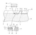
- 2 and 3 show a state in which the electrode precursor 20 is cut by the laser light ⁇ output from the laser system 30.
- the member used as the core 11 of the electrode 10 for secondary batteries by cutting the electrode precursor 20 be the elongate core 21, and the layer used as the active material layer 12 be the active material layer 22.
- the secondary battery electrode 10 is obtained by cutting a long electrode precursor 20 in which an active material layer 22 is formed on both surfaces of a long core 21 into a predetermined shape.
- the manufacturing process of the secondary battery electrode 10 includes a first process of forming the active material layer 22 on at least one surface of the elongated core body 21 and an electrode precursor 20 using a continuous wave laser (CW laser). And a second step of cutting.
- active material layers 22 are formed on both surfaces of the elongated core 21 in the first step.
- a mixture slurry containing the constituent material of the active material layer 22 is prepared, the slurry is applied to both surfaces of the elongated core body 21, and the coating film is dried to form the active material layer 22. .
- the exposed portion 23 where the core surface 21 s is exposed is formed along the longitudinal direction of the electrode precursor 20.
- the exposed portion 23 is preferably formed with a substantially constant width from one end in the width direction of the long core 21.
- the width of the exposed portion 23 is, for example, 1/5 or less of the width of the long core 21.
- the exposed portion 23 may be formed by forming the active material layer 22 on both sides of the long core 21 and then peeling and removing a part of the active material layer 22. It is formed by not applying the mixture slurry to a part of the body 21.
- the elongate core 21 has a width capable of forming two secondary battery electrodes 10 in the width direction, for example. In this case, exposed portions 23 are formed at both ends in the width direction of the electrode precursor 20.
- the electrode precursor 20 is irradiated with the laser beam ⁇ output from the laser system 30 to cut the electrode precursor 20 into a predetermined shape.
- the electrode precursor 20 is irradiated with the laser beam ⁇ while the relative position between the electrode precursor 20 and the processing head of the laser system 30 is changed.
- a cutting process may be performed while the electrode precursor 20 is being conveyed.
- the laser beam ⁇ may be scanned while conveying the electrode precursor 20.
- the laser system 30 includes a laser oscillator 31 and a processing head that incorporates a galvano scanner 33.
- the laser oscillator 31 is an oscillator capable of continuous oscillation.
- Examples of the laser oscillator 31 include a YAG laser, a CO 2 laser, an Ar laser, and a fiber laser that can output the laser light ⁇ in the continuous oscillation mode.
- a suitable example is a fiber laser.
- An example of a preferable range of the oscillation wavelength is 900 nm to 1200 nm.
- a collimator 32 is provided between the laser oscillator 31 and the galvano scanner 33 so that the laser light ⁇ output from the laser oscillator 31 is a parallel beam.
- the galvano scanner 33 includes, in order from the laser oscillator 31 side, a reflection mirror 34, an optical element 35, an X-axis mirror 36, a Y-axis mirror 37, and an F ⁇ lens 38.
- a reflection mirror 34 for example, a diffraction grating or the like is used.
- the laser light ⁇ which is a continuous wave that has passed through the collimator 32 is bent toward the optical element 35 by the reflection mirror 34, passes through the optical element 35, and is guided to the X-axis mirror 36 and the Y-axis mirror 37.
- the laser beam ⁇ can be scanned, and the position of the irradiation spot P can be changed in the two-dimensional plane.
- the laser light ⁇ reflected by the X-axis mirror 36 and the Y-axis mirror 37 is irradiated to the electrode precursor 20 through the F ⁇ lens 38 and the protective glass 39.
- a portion of the electrode precursor 20 provided with the active material layer 22 is cut along the exposed portion 23 using a continuous wave laser, and cut at a substantially constant period.
- a convex portion 24 to be the lead portion 14 is formed.
- the laser beam ⁇ can be applied to the boundary position between the portion where the active material layer 22 is provided and the exposed portion 23.
- the surface of the core body is applied to a portion other than the lead portion 14 due to slight deviation of the irradiation spot P. An exposed portion of 11s is formed.
- the exposed portion formed in a portion other than the lead portion 14 may cause a low-resistance short circuit between the positive and negative electrodes, it is preferable to cut the electrode precursor 20 so that the exposed portion is not formed particularly in the positive electrode. . For this reason, it is preferable to cut the electrode precursor 20 by irradiating the portion where the active material layer 22 near the exposed portion 23 is provided with the laser beam ⁇ .
- the laser beam ⁇ is scanned along the exposed portion 23 (longitudinal direction of the electrode precursor 20), and is scanned toward the exposed portion 23 (width direction of the electrode precursor 20) at a portion corresponding to the convex portion 24. Since the laser beam ⁇ is continuously irradiated even at the boundary position between the portion where the active material layer 22 is provided and the exposed portion 23, the cut portion C 22 where the active material layer 22 is provided and the exposed portion 23. the cut portion C 23 of, are formed into a continuous single linear. By cutting the exposed portion 23 while changing the cutting direction at a substantially constant cycle, a plurality of convex portions 24 arranged at substantially equal intervals in the longitudinal direction of the electrode precursor 20 are formed. And the electrode 10 for secondary batteries which has the base 13 in which the active material layer 12 was formed in the whole, and the lead part 14 in which the active material layer 12 was formed in the root is obtained.
- the electrode precursor 20 may be cut into an electrode size using a continuous wave laser.
- the electrode precursor 20 is cut along the longitudinal direction at the center.
- an electrode precursor 20 cut to a width corresponding to one electrode 10 for a secondary battery is obtained.
- a continuous wave laser is used for the cutting step. Is preferred.
- the electrode precursor 20 having a size adjusted to a width corresponding to one secondary battery electrode 10 may be supplied to the compression step of the active material layer 22.
- the active material layer may be compressed after the electrode precursor 20 is cut at the planned cutting portion X to obtain individual electrode sizes.
- the step of cutting the electrode precursor 20 at the planned cutting portion X may be performed using a continuous wave laser, or may be performed using a conventional general cutting method using a cutter or the like.
- FIG. 4 is a scanning electron microscope (SEM) photograph taken of a cross section of the cut portion C 22 of the electrode precursor 20 and the vicinity thereof.
- SEM scanning electron microscope
- the protrusion height of the protrusion 25 from the upper surface of the active material layer 22 is preferably 10 ⁇ m to 100 ⁇ m, and more preferably 10 ⁇ m to 80 ⁇ m.
- the protrusion 25 is formed on the surface of the active material layer 22 on the side on which the laser beam ⁇ is incident first.
- Such protrusions 25 are preferably removed because they may cause a short circuit between the positive and negative electrodes.
- the protrusion 25 can be embedded in the active material layer 22, or the protrusion 25 can be dropped from the active material layer 22. Further, the formation of the protrusions 25 can be suppressed by controlling the laser irradiation conditions.
- the angle ⁇ 1 formed by the end surface 22e of the active material layer 22 on the side on which the laser light ⁇ first enters and the core surface 21s is
- the angle is preferably 55 ° to 85 °.
- the core surface 21 s is not covered with the active material layer 22 and is not exposed, and both the cut portions C 22 and C 23 become a beautiful straight cut portion.
- the angle ⁇ 1 is preferably substantially the same as the angle ⁇ 2 formed by the surface of the opposite side active material layer 22 and the end face 22e, for example.
- the laser irradiation conditions are preferably adjusted based on the material, thickness, cut shape, and the like of the long core 21 and the active material layer 22, but generally the output of the continuous wave laser (laser oscillator 31) is 500 W to 5000 W.
- the spot diameter of the laser beam ⁇ is preferably 5 ⁇ m to 100 ⁇ m.
- the cutting speed of the electrode precursor 20 by the continuous wave laser is preferably set to, for example, 500 mm / s to 8000 mm / s. Irradiation conditions may be changed depending on whether the electrode precursor 20 is a positive electrode precursor or a negative electrode precursor. In general, the positive electrode precursor is easier to cut.
- the laser output is preferably 1000W to 3000W.
- the spot diameter is preferably 10 ⁇ m to 100 ⁇ m, more preferably 10 ⁇ m to 40 ⁇ m.
- the cutting speed is more preferably 1000 mm / s to 5000 mm / s.
- FIG. 5 is a diagram showing the relationship between laser output and cutting speed.
- the laser output is preferably 1000 W to 3000 W and the cutting speed is preferably 1000 mm / s to 5000 mm / s, but the laser output and the cutting speed are more preferably in a relationship indicated by a triangle in FIG. That is, the first point of laser output: 1000 W, cutting speed: 1000 mm / s, the second point of laser output: 3000 W, cutting speed: 1000 mm / s, the laser output: 3000 W, the cutting speed: 5000 mm / s. It is preferable to adjust the laser output and the cutting speed so as to fall within a triangle whose vertex is the third point.
- the laser output and the cutting speed within the range indicated by the triangle in FIG. 5, it becomes easy to form a straight and clean cut portion, and the formation of the protrusion 25 can be suppressed. Moreover, if the cutting speed is 1000 mm / s or more, good productivity can be secured.
- irradiation conditions are appropriately changed within the range of the triangle according to the material, thickness, cut shape, and the like of the long core 21 and the active material layer 22. For example, when a condition close to the third point with a laser output of 3000 W and a cutting speed of 5000 mm / s is applied, cutting can be performed at a higher speed than when other conditions close to the two points are applied. There is a tendency that the cut portion becomes rough. For this reason, when the cutting shape is simple, a condition close to the third point may be applied.
- the manufacturing process of the secondary battery electrode 10 further includes a process of compressing the active material layer cut by the continuous wave laser.
- the compression of the active material layer is performed using, for example, a rolling roller that sandwiches the electrode precursor 20 from both sides.
- the compression step of the active material layer may be performed before the second step, which is a cutting step of the electrode precursor 20, but is preferably performed after the second step.
- the compression process is performed after the second process, even if the protrusion 25 is formed by cutting with a continuous wave laser, the protrusion 25 is crushed and embedded in the active material layer, or the protrusion 25 is dropped from the active material layer. be able to.
- the compression process may be performed after the electrode precursor 20 is cut into individual electrode sizes. However, in consideration of productivity, for example, an electrode whose size is adjusted to a width corresponding to one electrode 10 for a secondary battery It is preferably performed in the state of the precursor 20. And it is preferable to cut
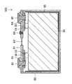
- an electrode body 50 in which a plurality of positive electrodes and a plurality of negative electrodes are alternately stacked via a separator is formed in a battery case 60 together with an electrolytic solution (not shown).
- the electrode 10 for secondary batteries is used as a positive electrode or a negative electrode.
- the opening of the battery case 60 is sealed with a sealing body 61.
- the positive electrode terminal 62 and the negative electrode terminal 63 are fixed to the sealing body 61 via resin members 64 and 65, respectively.
- the positive electrode is electrically connected to the positive electrode terminal 62 via the positive electrode lead portion 51 and the positive electrode current collecting member 52.
- the negative electrode is electrically connected to the negative electrode terminal 63 via the negative electrode lead portion 53 and the negative electrode current collecting member 54.
- the sealing body 61 is provided with a liquid injection hole for injecting an electrolytic solution.
- the liquid injection hole is sealed with a sealing member 66 after the electrolytic solution is injected.
- the sealing body 61 is provided with a gas discharge valve 67 for releasing the pressure when the internal pressure of the battery case 60 rises.
- the electrode body 50 is preferably disposed in the battery case 60 in a state where the electrode body 50 is disposed inside the box-shaped or bag-shaped insulating sheet 55.
- the positive electrode lead portion 51 protruding from each positive electrode is in a curved state and connected to a portion of the positive electrode current collecting member 52 that is disposed substantially parallel to the sealing body 61.
- the negative electrode lead portion 53 protruding from each negative electrode is in a curved state and connected to a portion of the negative electrode current collecting member 54 that is disposed substantially parallel to the sealing body 61.
- the positive electrode or the negative electrode manufactured by the above method having an end face cut by a continuous wave laser is bonded to a separator disposed between the positive electrode and the negative electrode.
- an adhesion method it is preferable to provide an adhesive layer on the surface of a separator made of polyolefin such as polypropylene or polyethylene, or on the surface of the active material layer of the electrode, and bond the separator and the active material layer with this adhesive layer.
- the adhesive layer is not particularly limited, but is preferably a layer softer than the separator.
- the adhesive layer is preferably made of a resin, and for example, polyvinylidene fluoride, carboxymethyl cellulose, polyvinyl alcohol, or the like can be used.
- the adhesive layer is preferably in contact with the projection mark 15. Thereby, when using a secondary battery, it can prevent that the protrusion trace 15 slips off from an active material layer.
- the electrolyte solution may not easily penetrate into the active material layer.
- the angle ⁇ 1 formed between the end surface 12e of the active material layer 12 and the core surface 11s is 55 ° to 85 °, the area of the end surface of the active material layer increases, and therefore the inside of the active material layer It becomes easy for the electrolyte solution to penetrate into.
- a protective layer made of ceramic particles such as alumina, zirconia, and titania and a binder may be provided in a portion adjacent to the active material layer 22 in the lead portion 14.
- the protective layer can also contain a conductive material such as a carbon material.
- the method for producing a secondary battery electrode according to the present disclosure is applied as a method for producing a positive electrode or a negative electrode, which is used for a wound electrode body in which a long positive electrode and a long negative electrode are wound through a separator. It is possible. In this case, a plurality of positive electrode lead portions provided on the positive electrode and a plurality of negative electrode lead portions provided on the negative electrode are disposed on one end side in the direction in which the winding axis of the wound electrode body extends. It is preferable to do so. Thereby, it becomes a secondary battery with higher volume energy density.
- the plurality of positive electrode lead portions provided on the long positive electrode are preferably formed at different intervals so that the plurality of positive electrode lead portions are stacked in the wound electrode body, not at equal intervals. .
- An elongate positive electrode has an active material layer formed on both sides of the core, and the amount of the active material layer of the active material layer on one side (the upper active material layer in FIG. 1) is the other side.
- the amount of the active material layer on the side (the lower active material layer in FIG. 1) is smaller, the active material layer on the one side with the smaller amount of the active material layer is disposed on the winding center side of the wound electrode body It is preferable to do so.
- the amount of the negative electrode active material layer located inside the positive electrode is usually smaller than the amount of the negative electrode active material layer located outside. Therefore, in the above-described configuration, the opposing balance between the positive electrode active material layer and the negative electrode active material layer is more preferable.
- SYMBOLS 10 Secondary battery electrode, 11 core, 11s core surface, 12 active material layer, 12e, 22e end face, 13 base, 14 lead part, 15 projection trace, 20 electrode precursor, 21 long core, 21s Core surface, 22 active material layer, 22e end face, 23 exposed part, 24 convex part, 25 protrusion, 30 laser system, 31 laser oscillator, 32 collimator, 33 galvano scanner, 34 reflecting mirror, 35 optical element, 36 X axis mirror , 37 Y-axis mirror, 38 F ⁇ lens, 39 protective glass, 100 secondary battery, C 22 , C 23 cutting part, ⁇ laser beam, P irradiation spot, X cutting scheduled part
Landscapes
- Engineering & Computer Science (AREA)
- Optics & Photonics (AREA)
- Physics & Mathematics (AREA)
- Chemical & Material Sciences (AREA)
- Chemical Kinetics & Catalysis (AREA)
- General Chemical & Material Sciences (AREA)
- Electrochemistry (AREA)
- Plasma & Fusion (AREA)
- Mechanical Engineering (AREA)
- Manufacturing & Machinery (AREA)
- Materials Engineering (AREA)
- Battery Electrode And Active Subsutance (AREA)
- Laser Beam Processing (AREA)
- Connection Of Batteries Or Terminals (AREA)
Abstract
La présente invention concerne un procédé de fabrication d'une électrode de batterie rechargeable, ledit procédé permettant la fabrication stable et à grande vitesse d'une électrode de batterie secondaire comportant une partie à coupe nette droite Un procédé de fabrication d'une électrode de batterie rechargeable (10) selon un mode de réalisation de la présente invention comprend une première étape de formation d'une couche de matériau actif (22) sur au moins une surface d'un corps de noyau long (21). Le procédé de fabrication de l'électrode de batterie rechargeable (10) selon le mode de réalisation de la présente invention comprend en outre une deuxième étape de découpe d'un précurseur d'électrode (20) qui est le corps de noyau long (21) comportant la couche de matériau actif (22) formée sur celui-ci, en une forme prescrite au moyen d'un laser à oscillation continue.
Priority Applications (2)
| Application Number | Priority Date | Filing Date | Title |
|---|---|---|---|
| CN201780052883.2A CN109643786B (zh) | 2016-08-31 | 2017-08-29 | 二次电池用电极的制造方法和二次电池的制造方法 |
| US16/327,997 US11527744B2 (en) | 2016-08-31 | 2017-08-29 | Secondary-battery electrode and secondary-battery electrode manufacturing method, and secondary battery and method of manufacturing secondary battery |
Applications Claiming Priority (2)
| Application Number | Priority Date | Filing Date | Title |
|---|---|---|---|
| JP2016170071A JP6931277B2 (ja) | 2016-08-31 | 2016-08-31 | 二次電池用電極の製造方法、及び二次電池の製造方法 |
| JP2016-170071 | 2016-08-31 |
Publications (1)
| Publication Number | Publication Date |
|---|---|
| WO2018043443A1 true WO2018043443A1 (fr) | 2018-03-08 |
Family
ID=61300673
Family Applications (1)
| Application Number | Title | Priority Date | Filing Date |
|---|---|---|---|
| PCT/JP2017/030827 Ceased WO2018043443A1 (fr) | 2016-08-31 | 2017-08-29 | Électrode de batterie rechargeable, son procédé de fabrication, batterie rechargeable et son procédé de fabrication |
Country Status (4)
| Country | Link |
|---|---|
| US (1) | US11527744B2 (fr) |
| JP (1) | JP6931277B2 (fr) |
| CN (1) | CN109643786B (fr) |
| WO (1) | WO2018043443A1 (fr) |
Cited By (6)
| Publication number | Priority date | Publication date | Assignee | Title |
|---|---|---|---|---|
| WO2020120096A1 (fr) * | 2018-12-10 | 2020-06-18 | Robert Bosch Gmbh | Empilement d'électrodes pour une cellule galvanique |
| WO2020137714A1 (fr) * | 2018-12-27 | 2020-07-02 | 三洋電機株式会社 | Batterie secondaire |
| CN114824490A (zh) * | 2021-01-29 | 2022-07-29 | 泰星能源解决方案有限公司 | 二次电池的制造方法以及二次电池 |
| JP2023053696A (ja) * | 2021-10-01 | 2023-04-13 | 古河電気工業株式会社 | 金属箔のレーザ切断方法 |
| US20230135592A1 (en) * | 2020-03-27 | 2023-05-04 | Sanyo Electric Co., Ltd. | Electrode plate for secondary battery, method for producing same, secondary battery, and method for producing same |
| JP2025531594A (ja) * | 2022-09-19 | 2025-09-22 | 珠海冠宇電池股分有限公司 | 電池極板、セルおよび電池 |
Families Citing this family (14)
| Publication number | Priority date | Publication date | Assignee | Title |
|---|---|---|---|---|
| US20220021001A1 (en) * | 2018-12-27 | 2022-01-20 | Sanyo Electric Co., Ltd. | Electrode plate and secondary battery using same |
| WO2021058925A1 (fr) * | 2019-09-26 | 2021-04-01 | Saverglass | Procede de marquage a but decoratif d'articles en verre a haute temperature par laser |
| CN114514646B (zh) | 2019-09-30 | 2023-11-28 | 株式会社村田制作所 | 二次电池 |
| KR102803271B1 (ko) * | 2019-10-24 | 2025-05-07 | 주식회사 엘지에너지솔루션 | 레이저 식각을 이용한 전극 제조방법 및 이를 수행하는 전극 제조설비 |
| KR102873026B1 (ko) * | 2021-01-08 | 2025-10-17 | 주식회사 엘지에너지솔루션 | 전극의 절단방법 및 절단장치 |
| DE102021202644A1 (de) * | 2021-03-18 | 2022-09-22 | Volkswagen Aktiengesellschaft | Verfahren zur Herstellung einer Ableiterfolie für Batterien |
| CN115555852B (zh) * | 2021-06-30 | 2023-06-30 | 宁德时代新能源科技股份有限公司 | 极片成型方法及设备 |
| US20230034980A1 (en) * | 2021-07-29 | 2023-02-02 | Samsung Sdi Co., Ltd. | Cutting device and method for cutting an electrode foil for a secondary battery cell |
| CN115890095B (zh) * | 2021-09-30 | 2023-11-28 | 宁德时代新能源科技股份有限公司 | 一种电池组件装配方法、夹具及焊接设备 |
| JP7583704B2 (ja) | 2021-12-27 | 2024-11-14 | プライムプラネットエナジー&ソリューションズ株式会社 | 電極板の製造方法、二次電池の製造方法、電極板および二次電池 |
| US12330239B2 (en) * | 2022-02-09 | 2025-06-17 | Ford Global Technologies, Llc | Laser notching apparatus for cutting of electrode sheets |
| CN115064806B (zh) * | 2022-08-03 | 2025-08-22 | 武汉蔚能电池资产有限公司 | 一种激光切割装置以及电池回收系统 |
| JP2025537722A (ja) * | 2022-11-16 | 2025-11-20 | エルジー エナジー ソリューション リミテッド | 電極組立体および該電極組立体を含むバッテリー、並びに該バッテリーを含むバッテリーパックおよび自動車 |
| KR102792583B1 (ko) | 2024-03-28 | 2025-04-04 | 삼성에스디아이 주식회사 | 이차 전지용 전극 및 이의 제조 방법 |
Citations (6)
| Publication number | Priority date | Publication date | Assignee | Title |
|---|---|---|---|---|
| JPH02170351A (ja) * | 1988-12-22 | 1990-07-02 | Matsushita Electric Ind Co Ltd | 円筒形電池とその製造法 |
| JP2006139919A (ja) * | 2004-11-10 | 2006-06-01 | Ngk Spark Plug Co Ltd | リチウムイオン二次電池およびその製造方法 |
| JP2010034009A (ja) * | 2008-07-31 | 2010-02-12 | Nec Tokin Corp | 積層型二次電池およびその製造方法 |
| JP2016033912A (ja) * | 2014-07-30 | 2016-03-10 | 三星エスディアイ株式会社Samsung SDI Co.,Ltd. | 二次電池およびその製造方法 |
| WO2016208679A1 (fr) * | 2015-06-24 | 2016-12-29 | 株式会社豊田自動織機 | Procédé de fabrication d'électrode, et électrode |
| WO2017110318A1 (fr) * | 2015-12-25 | 2017-06-29 | 株式会社豊田自動織機 | Dispositif de stockage d'électricité et procédé de fabrication d'unité d'électrode |
Family Cites Families (22)
| Publication number | Priority date | Publication date | Assignee | Title |
|---|---|---|---|---|
| JP2001176501A (ja) | 1999-12-16 | 2001-06-29 | Sony Corp | 非水電解質電池の製造方法 |
| JP5011632B2 (ja) * | 2004-06-29 | 2012-08-29 | Tdk株式会社 | スリッター装置及び電極の製造方法 |
| JP2007014993A (ja) | 2005-07-08 | 2007-01-25 | Toyota Motor Corp | レーザを用いたワーク切断方法とレーザ加工装置 |
| JP5008849B2 (ja) * | 2005-09-08 | 2012-08-22 | ソニーモバイルディスプレイ株式会社 | レーザ加工方法及び透明樹脂層を有する表示装置の製造方法 |
| KR20080058772A (ko) * | 2006-12-22 | 2008-06-26 | 에스케이에너지 주식회사 | 전지용 전극의 제조 방법 |
| JP2008194729A (ja) * | 2007-02-13 | 2008-08-28 | Fujitsu Ltd | 小型デバイスの製造方法、レーザ加工方法及びレーザ加工装置 |
| JP5225639B2 (ja) * | 2007-09-06 | 2013-07-03 | 浜松ホトニクス株式会社 | 半導体レーザ素子の製造方法 |
| JP4667495B2 (ja) * | 2007-11-05 | 2011-04-13 | パナソニック株式会社 | ローラ加工方法、およびローラ加工装置 |
| BR112012019544A2 (pt) * | 2010-02-04 | 2018-03-27 | Echelon Laser Systems Lp | metodo e sistema de corte com laser |
| JP2012221912A (ja) * | 2011-04-14 | 2012-11-12 | Nissan Motor Co Ltd | 電極製造方法および電極製造装置 |
| CN104870116A (zh) * | 2012-12-27 | 2015-08-26 | 村田机械株式会社 | 激光加工机的修边工具及其修边方法 |
| DE102013203810A1 (de) * | 2013-03-06 | 2014-09-11 | Thyssenkrupp System Engineering Gmbh | Verfahren und Vorrichtung zum Schneiden eines Elektrodenbands |
| US9048635B2 (en) * | 2013-03-13 | 2015-06-02 | Federal-Mogul Ignition Company | Spark plug with laser keyhole weld attaching ground electrode to shell |
| JP6064228B2 (ja) * | 2013-05-24 | 2017-01-25 | パナソニックIpマネジメント株式会社 | レーザ切断装置およびレーザ切断方法 |
| JP2015084279A (ja) * | 2013-10-25 | 2015-04-30 | トヨタ自動車株式会社 | 二次電池 |
| KR101680416B1 (ko) * | 2013-11-01 | 2016-12-12 | 주식회사 엘지화학 | 레이저를 이용한 양극 커팅 장치 |
| US10218029B2 (en) * | 2014-02-28 | 2019-02-26 | Nec Energy Devices, Ltd. | Electrode for secondary battery, secondary battery, and manufacturing method of the electrode and the secondary battery |
| CN104051705B (zh) * | 2014-07-07 | 2017-01-18 | 合肥国轩高科动力能源有限公司 | 一种高效多极耳卷绕式电池制片设备 |
| CN105322057B (zh) * | 2014-07-25 | 2020-03-20 | 晶元光电股份有限公司 | 发光元件及其制造方法 |
| JP6464687B2 (ja) * | 2014-11-13 | 2019-02-06 | 株式会社豊田自動織機 | 電極の製造方法及び電極のクリーニング装置 |
| JP6413697B2 (ja) * | 2014-11-25 | 2018-10-31 | 株式会社豊田自動織機 | 電極の製造方法および電極の製造装置 |
| WO2017119010A1 (fr) * | 2016-01-06 | 2017-07-13 | オー・エム・シー株式会社 | Procédé de division de matériau enroulé brut, et mécanisme ainsi que dispositif de division associé |
-
2016
- 2016-08-31 JP JP2016170071A patent/JP6931277B2/ja active Active
-
2017
- 2017-08-29 WO PCT/JP2017/030827 patent/WO2018043443A1/fr not_active Ceased
- 2017-08-29 US US16/327,997 patent/US11527744B2/en active Active
- 2017-08-29 CN CN201780052883.2A patent/CN109643786B/zh active Active
Patent Citations (6)
| Publication number | Priority date | Publication date | Assignee | Title |
|---|---|---|---|---|
| JPH02170351A (ja) * | 1988-12-22 | 1990-07-02 | Matsushita Electric Ind Co Ltd | 円筒形電池とその製造法 |
| JP2006139919A (ja) * | 2004-11-10 | 2006-06-01 | Ngk Spark Plug Co Ltd | リチウムイオン二次電池およびその製造方法 |
| JP2010034009A (ja) * | 2008-07-31 | 2010-02-12 | Nec Tokin Corp | 積層型二次電池およびその製造方法 |
| JP2016033912A (ja) * | 2014-07-30 | 2016-03-10 | 三星エスディアイ株式会社Samsung SDI Co.,Ltd. | 二次電池およびその製造方法 |
| WO2016208679A1 (fr) * | 2015-06-24 | 2016-12-29 | 株式会社豊田自動織機 | Procédé de fabrication d'électrode, et électrode |
| WO2017110318A1 (fr) * | 2015-12-25 | 2017-06-29 | 株式会社豊田自動織機 | Dispositif de stockage d'électricité et procédé de fabrication d'unité d'électrode |
Cited By (10)
| Publication number | Priority date | Publication date | Assignee | Title |
|---|---|---|---|---|
| WO2020120096A1 (fr) * | 2018-12-10 | 2020-06-18 | Robert Bosch Gmbh | Empilement d'électrodes pour une cellule galvanique |
| WO2020137714A1 (fr) * | 2018-12-27 | 2020-07-02 | 三洋電機株式会社 | Batterie secondaire |
| JPWO2020137714A1 (ja) * | 2018-12-27 | 2021-11-11 | 三洋電機株式会社 | 二次電池 |
| JP7353302B2 (ja) | 2018-12-27 | 2023-09-29 | 三洋電機株式会社 | 二次電池 |
| US12438242B2 (en) | 2018-12-27 | 2025-10-07 | Sanyo Electric Co., Ltd. | Secondary battery |
| US20230135592A1 (en) * | 2020-03-27 | 2023-05-04 | Sanyo Electric Co., Ltd. | Electrode plate for secondary battery, method for producing same, secondary battery, and method for producing same |
| CN114824490A (zh) * | 2021-01-29 | 2022-07-29 | 泰星能源解决方案有限公司 | 二次电池的制造方法以及二次电池 |
| JP2023053696A (ja) * | 2021-10-01 | 2023-04-13 | 古河電気工業株式会社 | 金属箔のレーザ切断方法 |
| JP7704641B2 (ja) | 2021-10-01 | 2025-07-08 | 古河電気工業株式会社 | 金属箔のレーザ切断方法 |
| JP2025531594A (ja) * | 2022-09-19 | 2025-09-22 | 珠海冠宇電池股分有限公司 | 電池極板、セルおよび電池 |
Also Published As
| Publication number | Publication date |
|---|---|
| US11527744B2 (en) | 2022-12-13 |
| JP2018037308A (ja) | 2018-03-08 |
| CN109643786B (zh) | 2021-11-16 |
| US20190198853A1 (en) | 2019-06-27 |
| JP6931277B2 (ja) | 2021-09-01 |
| CN109643786A (zh) | 2019-04-16 |
Similar Documents
| Publication | Publication Date | Title |
|---|---|---|
| JP6931277B2 (ja) | 二次電池用電極の製造方法、及び二次電池の製造方法 | |
| CN109690829B (zh) | 二次电池用电极和二次电池 | |
| TWI397203B (zh) | Laminated type secondary battery and manufacturing method thereof | |
| US10283815B2 (en) | Production method of laminate for a battery | |
| US20110195288A1 (en) | Sealed battery and method for fabricating the same | |
| CN109834393B (zh) | 电极片制造装置和蓄电装置的制造方法 | |
| CN111279523B (zh) | 二次电池用的电极以及使用了该电极的二次电池 | |
| US11557794B2 (en) | Solid-state battery and method of manufacture thereof | |
| JP2009259697A (ja) | 電池およびその製造方法 | |
| CN113039662B (zh) | 二次电池用的电极板和使用了该电极板的二次电池 | |
| US12548860B2 (en) | Electrode plate for secondary cell, and secondary cell using same | |
| JP6727990B2 (ja) | 二次電池用電極の製造方法、及び二次電池の製造方法 | |
| WO2020137714A1 (fr) | Batterie secondaire | |
| US20240178460A1 (en) | Positive electrode for lithium-ion battery, battery core, and lithium-ion battery | |
| JP3178500U (ja) | リード部材 | |
| CN115398665B (zh) | 二次电池用电极板及其制造方法、以及二次电池及其制造方法 | |
| JP2021034242A (ja) | 全固体電池の製造方法 |
Legal Events
| Date | Code | Title | Description |
|---|---|---|---|
| 121 | Ep: the epo has been informed by wipo that ep was designated in this application |
Ref document number: 17846448 Country of ref document: EP Kind code of ref document: A1 |
|
| NENP | Non-entry into the national phase |
Ref country code: DE |
|
| 122 | Ep: pct application non-entry in european phase |
Ref document number: 17846448 Country of ref document: EP Kind code of ref document: A1 |