WO2018092187A1 - Outil de coupe - Google Patents
Outil de coupe Download PDFInfo
- Publication number
- WO2018092187A1 WO2018092187A1 PCT/JP2016/083803 JP2016083803W WO2018092187A1 WO 2018092187 A1 WO2018092187 A1 WO 2018092187A1 JP 2016083803 W JP2016083803 W JP 2016083803W WO 2018092187 A1 WO2018092187 A1 WO 2018092187A1
- Authority
- WO
- WIPO (PCT)
- Prior art keywords
- cutting
- cutting tool
- structure forming
- flank
- core
- Prior art date
- Legal status (The legal status is an assumption and is not a legal conclusion. Google has not performed a legal analysis and makes no representation as to the accuracy of the status listed.)
- Ceased
Links
Images





Classifications
-
- B—PERFORMING OPERATIONS; TRANSPORTING
- B23—MACHINE TOOLS; METAL-WORKING NOT OTHERWISE PROVIDED FOR
- B23C—MILLING
- B23C5/00—Milling-cutters
- B23C5/02—Milling-cutters characterised by the shape of the cutter
- B23C5/10—Shank-type cutters, i.e. with an integral shaft
- B23C5/1054—T slot cutters
-
- B—PERFORMING OPERATIONS; TRANSPORTING
- B23—MACHINE TOOLS; METAL-WORKING NOT OTHERWISE PROVIDED FOR
- B23D—PLANING; SLOTTING; SHEARING; BROACHING; SAWING; FILING; SCRAPING; LIKE OPERATIONS FOR WORKING METAL BY REMOVING MATERIAL, NOT OTHERWISE PROVIDED FOR
- B23D77/00—Reaming tools
-
- B—PERFORMING OPERATIONS; TRANSPORTING
- B23—MACHINE TOOLS; METAL-WORKING NOT OTHERWISE PROVIDED FOR
- B23B—TURNING; BORING
- B23B27/00—Tools for turning or boring machines; Tools of a similar kind in general; Accessories therefor
- B23B27/14—Cutting tools of which the bits or tips or cutting inserts are of special material
-
- B—PERFORMING OPERATIONS; TRANSPORTING
- B23—MACHINE TOOLS; METAL-WORKING NOT OTHERWISE PROVIDED FOR
- B23B—TURNING; BORING
- B23B51/00—Tools for drilling machines
-
- B—PERFORMING OPERATIONS; TRANSPORTING
- B23—MACHINE TOOLS; METAL-WORKING NOT OTHERWISE PROVIDED FOR
- B23C—MILLING
- B23C5/00—Milling-cutters
- B23C5/02—Milling-cutters characterised by the shape of the cutter
- B23C5/10—Shank-type cutters, i.e. with an integral shaft
-
- B—PERFORMING OPERATIONS; TRANSPORTING
- B23—MACHINE TOOLS; METAL-WORKING NOT OTHERWISE PROVIDED FOR
- B23C—MILLING
- B23C5/00—Milling-cutters
- B23C5/28—Features relating to lubricating or cooling
-
- B—PERFORMING OPERATIONS; TRANSPORTING
- B22—CASTING; POWDER METALLURGY
- B22F—WORKING METALLIC POWDER; MANUFACTURE OF ARTICLES FROM METALLIC POWDER; MAKING METALLIC POWDER; APPARATUS OR DEVICES SPECIALLY ADAPTED FOR METALLIC POWDER
- B22F5/00—Manufacture of workpieces or articles from metallic powder characterised by the special shape of the product
- B22F2005/002—Tools other than cutting tools
-
- B—PERFORMING OPERATIONS; TRANSPORTING
- B22—CASTING; POWDER METALLURGY
- B22F—WORKING METALLIC POWDER; MANUFACTURE OF ARTICLES FROM METALLIC POWDER; MAKING METALLIC POWDER; APPARATUS OR DEVICES SPECIALLY ADAPTED FOR METALLIC POWDER
- B22F2998/00—Supplementary information concerning processes or compositions relating to powder metallurgy
- B22F2998/10—Processes characterised by the sequence of their steps
-
- B—PERFORMING OPERATIONS; TRANSPORTING
- B22—CASTING; POWDER METALLURGY
- B22F—WORKING METALLIC POWDER; MANUFACTURE OF ARTICLES FROM METALLIC POWDER; MAKING METALLIC POWDER; APPARATUS OR DEVICES SPECIALLY ADAPTED FOR METALLIC POWDER
- B22F2999/00—Aspects linked to processes or compositions used in powder metallurgy
-
- B—PERFORMING OPERATIONS; TRANSPORTING
- B22—CASTING; POWDER METALLURGY
- B22F—WORKING METALLIC POWDER; MANUFACTURE OF ARTICLES FROM METALLIC POWDER; MAKING METALLIC POWDER; APPARATUS OR DEVICES SPECIALLY ADAPTED FOR METALLIC POWDER
- B22F3/00—Manufacture of workpieces or articles from metallic powder characterised by the manner of compacting or sintering; Apparatus specially adapted therefor ; Presses and furnaces
- B22F3/02—Compacting only
-
- B—PERFORMING OPERATIONS; TRANSPORTING
- B22—CASTING; POWDER METALLURGY
- B22F—WORKING METALLIC POWDER; MANUFACTURE OF ARTICLES FROM METALLIC POWDER; MAKING METALLIC POWDER; APPARATUS OR DEVICES SPECIALLY ADAPTED FOR METALLIC POWDER
- B22F3/00—Manufacture of workpieces or articles from metallic powder characterised by the manner of compacting or sintering; Apparatus specially adapted therefor ; Presses and furnaces
- B22F3/10—Sintering only
-
- B—PERFORMING OPERATIONS; TRANSPORTING
- B22—CASTING; POWDER METALLURGY
- B22F—WORKING METALLIC POWDER; MANUFACTURE OF ARTICLES FROM METALLIC POWDER; MAKING METALLIC POWDER; APPARATUS OR DEVICES SPECIALLY ADAPTED FOR METALLIC POWDER
- B22F3/00—Manufacture of workpieces or articles from metallic powder characterised by the manner of compacting or sintering; Apparatus specially adapted therefor ; Presses and furnaces
- B22F3/12—Both compacting and sintering
- B22F3/14—Both compacting and sintering simultaneously
-
- B—PERFORMING OPERATIONS; TRANSPORTING
- B22—CASTING; POWDER METALLURGY
- B22F—WORKING METALLIC POWDER; MANUFACTURE OF ARTICLES FROM METALLIC POWDER; MAKING METALLIC POWDER; APPARATUS OR DEVICES SPECIALLY ADAPTED FOR METALLIC POWDER
- B22F7/00—Manufacture of composite layers, workpieces, or articles, comprising metallic powder, by sintering the powder, with or without compacting wherein at least one part is obtained by sintering or compression
- B22F7/06—Manufacture of composite layers, workpieces, or articles, comprising metallic powder, by sintering the powder, with or without compacting wherein at least one part is obtained by sintering or compression of composite workpieces or articles from parts, e.g. to form tipped tools
- B22F7/062—Manufacture of composite layers, workpieces, or articles, comprising metallic powder, by sintering the powder, with or without compacting wherein at least one part is obtained by sintering or compression of composite workpieces or articles from parts, e.g. to form tipped tools involving the connection or repairing of preformed parts
-
- B—PERFORMING OPERATIONS; TRANSPORTING
- B23—MACHINE TOOLS; METAL-WORKING NOT OTHERWISE PROVIDED FOR
- B23B—TURNING; BORING
- B23B2205/00—Fixation of cutting inserts in holders
- B23B2205/12—Seats for cutting inserts
- B23B2205/125—One or more walls of the seat being elastically deformable
-
- B—PERFORMING OPERATIONS; TRANSPORTING
- B23—MACHINE TOOLS; METAL-WORKING NOT OTHERWISE PROVIDED FOR
- B23B—TURNING; BORING
- B23B2222/00—Materials of tools or workpieces composed of metals, alloys or metal matrices
- B23B2222/16—Cermet
-
- B—PERFORMING OPERATIONS; TRANSPORTING
- B23—MACHINE TOOLS; METAL-WORKING NOT OTHERWISE PROVIDED FOR
- B23B—TURNING; BORING
- B23B2222/00—Materials of tools or workpieces composed of metals, alloys or metal matrices
- B23B2222/92—Tungsten
-
- B—PERFORMING OPERATIONS; TRANSPORTING
- B23—MACHINE TOOLS; METAL-WORKING NOT OTHERWISE PROVIDED FOR
- B23B—TURNING; BORING
- B23B2224/00—Materials of tools or workpieces composed of a compound including a metal
- B23B2224/04—Aluminium oxide
-
- B—PERFORMING OPERATIONS; TRANSPORTING
- B23—MACHINE TOOLS; METAL-WORKING NOT OTHERWISE PROVIDED FOR
- B23B—TURNING; BORING
- B23B2224/00—Materials of tools or workpieces composed of a compound including a metal
- B23B2224/28—Titanium carbide
-
- B—PERFORMING OPERATIONS; TRANSPORTING
- B23—MACHINE TOOLS; METAL-WORKING NOT OTHERWISE PROVIDED FOR
- B23B—TURNING; BORING
- B23B2224/00—Materials of tools or workpieces composed of a compound including a metal
- B23B2224/32—Titanium carbide nitride (TiCN)
-
- B—PERFORMING OPERATIONS; TRANSPORTING
- B23—MACHINE TOOLS; METAL-WORKING NOT OTHERWISE PROVIDED FOR
- B23B—TURNING; BORING
- B23B2226/00—Materials of tools or workpieces not comprising a metal
- B23B2226/12—Boron nitride
- B23B2226/125—Boron nitride cubic [CBN]
-
- B—PERFORMING OPERATIONS; TRANSPORTING
- B23—MACHINE TOOLS; METAL-WORKING NOT OTHERWISE PROVIDED FOR
- B23B—TURNING; BORING
- B23B2226/00—Materials of tools or workpieces not comprising a metal
- B23B2226/31—Diamond
- B23B2226/315—Diamond polycrystalline [PCD]
-
- B—PERFORMING OPERATIONS; TRANSPORTING
- B23—MACHINE TOOLS; METAL-WORKING NOT OTHERWISE PROVIDED FOR
- B23B—TURNING; BORING
- B23B2251/00—Details of tools for drilling machines
- B23B2251/02—Connections between shanks and removable cutting heads
-
- B—PERFORMING OPERATIONS; TRANSPORTING
- B23—MACHINE TOOLS; METAL-WORKING NOT OTHERWISE PROVIDED FOR
- B23C—MILLING
- B23C2210/00—Details of milling cutters
- B23C2210/02—Connections between the shanks and detachable cutting heads
-
- B—PERFORMING OPERATIONS; TRANSPORTING
- B23—MACHINE TOOLS; METAL-WORKING NOT OTHERWISE PROVIDED FOR
- B23C—MILLING
- B23C2210/00—Details of milling cutters
- B23C2210/03—Cutting heads comprised of different material than the shank irrespective of whether the head is detachable from the shank
-
- B—PERFORMING OPERATIONS; TRANSPORTING
- B23—MACHINE TOOLS; METAL-WORKING NOT OTHERWISE PROVIDED FOR
- B23C—MILLING
- B23C2222/00—Materials of tools or workpieces composed of metals, alloys or metal matrices
- B23C2222/16—Cermet
-
- B—PERFORMING OPERATIONS; TRANSPORTING
- B23—MACHINE TOOLS; METAL-WORKING NOT OTHERWISE PROVIDED FOR
- B23C—MILLING
- B23C2222/00—Materials of tools or workpieces composed of metals, alloys or metal matrices
- B23C2222/28—Details of hard metal, i.e. cemented carbide
-
- B—PERFORMING OPERATIONS; TRANSPORTING
- B23—MACHINE TOOLS; METAL-WORKING NOT OTHERWISE PROVIDED FOR
- B23C—MILLING
- B23C2224/00—Materials of tools or workpieces composed of a compound including a metal
- B23C2224/04—Aluminium oxide
-
- B—PERFORMING OPERATIONS; TRANSPORTING
- B23—MACHINE TOOLS; METAL-WORKING NOT OTHERWISE PROVIDED FOR
- B23C—MILLING
- B23C2224/00—Materials of tools or workpieces composed of a compound including a metal
- B23C2224/28—Titanium carbide
-
- B—PERFORMING OPERATIONS; TRANSPORTING
- B23—MACHINE TOOLS; METAL-WORKING NOT OTHERWISE PROVIDED FOR
- B23C—MILLING
- B23C2224/00—Materials of tools or workpieces composed of a compound including a metal
- B23C2224/32—Titanium carbide nitride (TiCN)
-
- B—PERFORMING OPERATIONS; TRANSPORTING
- B23—MACHINE TOOLS; METAL-WORKING NOT OTHERWISE PROVIDED FOR
- B23C—MILLING
- B23C2226/00—Materials of tools or workpieces not comprising a metal
- B23C2226/12—Boron nitride
- B23C2226/125—Boron nitride cubic [CBN]
-
- B—PERFORMING OPERATIONS; TRANSPORTING
- B23—MACHINE TOOLS; METAL-WORKING NOT OTHERWISE PROVIDED FOR
- B23C—MILLING
- B23C2226/00—Materials of tools or workpieces not comprising a metal
- B23C2226/31—Diamond
- B23C2226/315—Diamond polycrystalline [PCD]
-
- B—PERFORMING OPERATIONS; TRANSPORTING
- B23—MACHINE TOOLS; METAL-WORKING NOT OTHERWISE PROVIDED FOR
- B23D—PLANING; SLOTTING; SHEARING; BROACHING; SAWING; FILING; SCRAPING; LIKE OPERATIONS FOR WORKING METAL BY REMOVING MATERIAL, NOT OTHERWISE PROVIDED FOR
- B23D2277/00—Reaming tools
- B23D2277/02—Cutting head and shank made from two different components which are releasably or non-releasably attached to each other
-
- B—PERFORMING OPERATIONS; TRANSPORTING
- B23—MACHINE TOOLS; METAL-WORKING NOT OTHERWISE PROVIDED FOR
- B23D—PLANING; SLOTTING; SHEARING; BROACHING; SAWING; FILING; SCRAPING; LIKE OPERATIONS FOR WORKING METAL BY REMOVING MATERIAL, NOT OTHERWISE PROVIDED FOR
- B23D2277/00—Reaming tools
- B23D2277/06—Connections between component parts
- B23D2277/061—Brazed connections
-
- B—PERFORMING OPERATIONS; TRANSPORTING
- B23—MACHINE TOOLS; METAL-WORKING NOT OTHERWISE PROVIDED FOR
- B23D—PLANING; SLOTTING; SHEARING; BROACHING; SAWING; FILING; SCRAPING; LIKE OPERATIONS FOR WORKING METAL BY REMOVING MATERIAL, NOT OTHERWISE PROVIDED FOR
- B23D2277/00—Reaming tools
- B23D2277/24—Materials of the tool or the intended workpiece, methods of applying these materials
- B23D2277/2435—Cubic boron nitride [CBN]
-
- B—PERFORMING OPERATIONS; TRANSPORTING
- B23—MACHINE TOOLS; METAL-WORKING NOT OTHERWISE PROVIDED FOR
- B23D—PLANING; SLOTTING; SHEARING; BROACHING; SAWING; FILING; SCRAPING; LIKE OPERATIONS FOR WORKING METAL BY REMOVING MATERIAL, NOT OTHERWISE PROVIDED FOR
- B23D2277/00—Reaming tools
- B23D2277/24—Materials of the tool or the intended workpiece, methods of applying these materials
- B23D2277/2442—Diamond
- B23D2277/245—Diamond polycrystalline [PCD]
-
- B—PERFORMING OPERATIONS; TRANSPORTING
- B23—MACHINE TOOLS; METAL-WORKING NOT OTHERWISE PROVIDED FOR
- B23D—PLANING; SLOTTING; SHEARING; BROACHING; SAWING; FILING; SCRAPING; LIKE OPERATIONS FOR WORKING METAL BY REMOVING MATERIAL, NOT OTHERWISE PROVIDED FOR
- B23D2277/00—Reaming tools
- B23D2277/60—Reaming tools comprising means for lubrication or cooling
-
- C—CHEMISTRY; METALLURGY
- C22—METALLURGY; FERROUS OR NON-FERROUS ALLOYS; TREATMENT OF ALLOYS OR NON-FERROUS METALS
- C22C—ALLOYS
- C22C29/00—Alloys based on carbides, oxides, nitrides, borides, or silicides, e.g. cermets, or other metal compounds, e.g. oxynitrides, sulfides
- C22C29/02—Alloys based on carbides, oxides, nitrides, borides, or silicides, e.g. cermets, or other metal compounds, e.g. oxynitrides, sulfides based on carbides or carbonitrides
- C22C29/06—Alloys based on carbides, oxides, nitrides, borides, or silicides, e.g. cermets, or other metal compounds, e.g. oxynitrides, sulfides based on carbides or carbonitrides based on carbides, but not containing other metal compounds
- C22C29/067—Alloys based on carbides, oxides, nitrides, borides, or silicides, e.g. cermets, or other metal compounds, e.g. oxynitrides, sulfides based on carbides or carbonitrides based on carbides, but not containing other metal compounds comprising a particular metallic binder
Definitions
- This disclosure relates to a cutting tool.
- Rotating cutting tools such as drills and end mills use up cutting blades as they are used, so at least when the cutting performance deteriorates or after a specified period of use has elapsed, the cutting head that contains at least the cutting blade is a new cutting head. Will be replaced. At this time, if the cutting head is non-removably attached to the carbide shank, the carbide shank has not reached the end of its useful life, so even if it is not necessary to replace it, the timing for replacing the cutting blade At the same time, the carbide shank must be changed together. Such replacement of the carbide shank is not preferable from the viewpoint of cost because the carbide shank is relatively expensive.
- Patent Document 1 describes that a super-hard structure to be processed into a cutting blade is attached to a tool carrier. Specifically, the structure can be attached to the tool carrier by brazing the structure and the tool carrier, or providing the structure with attachment means such as a screw groove.
- a cutting tool includes a shank, an attachment portion attached to the shank, a core portion, a cutting portion having a surface portion covering the core portion around a central axis, and the attachment portion.
- a joining portion that joins the cutting portion.
- the attachment portion includes a hard component and a hard material.
- the hard component is at least one of TiC (titanium carbide), TiCN (titanium carbonitride), W (tungsten), WC (tungsten carbide), Al 2 O 3 (alumina), CBN (cubic boron nitride) and diamond. And at least one selected from the group consisting of a combination of at least one of W and WC.
- the hard material contains one or more iron group elements and has a Young's modulus of 350 GPa or less.
- the core portion includes a cemented carbide material.
- the surface portion includes PCD (polycrystalline diamond) or CBN.
- the cutting part has a biting part located at an end opposite to the attachment part.
- the surface portion includes a groove, a flank, and a cutting edge constituted by a ridge line between the groove and the flank.
- the cutting edge extends from the end toward the attachment portion.
- the said flank is comprised by the biting flank located in the said biting part, and the outer periphery flank located in other than the said biting part.
- the inclination of the biting flank with respect to the central axis is greater than the inclination of the outer peripheral flank with respect to the central axis.
- the manufacturing method of the raw material for cutting tools which concerns on the other aspect of this indication WHEREIN:
- FIG. 1A is a perspective view of a cutting tool material showing one embodiment of the present embodiment.
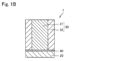
- 1B is a cross-sectional view taken along the line AA in FIG. 1A.
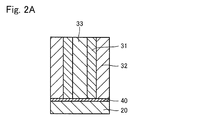
- FIG. 2A is a cross-sectional view of a cutting tool material showing another embodiment of the present embodiment.
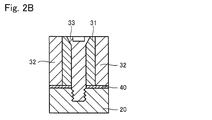
- FIG. 2B is a cross-sectional view of the cutting tool material showing another embodiment of the present embodiment.
- FIG. 2C is a cross-sectional view of a cutting tool material showing another embodiment of the present embodiment.
- FIG. 3 is a cross-sectional view of a cutting tool material showing still another embodiment of the present embodiment.
- FIG. 4 is a perspective view of a cutting tool material showing still another embodiment of the present embodiment.
- FIG. 1A is a perspective view of a cutting tool material showing one embodiment of the present embodiment.
- FIG. 2B is a cross-sectional view taken along the line AA in FIG. 1A.
- FIG. 2A is a cross-sectional view of a cutting tool material
- FIG. 5 is a perspective view of a cutting tool obtained from the cutting tool material 1 of the present embodiment.
- FIG. 6 is a perspective view of a first example of a rotary cutting tool using the cutting tool material 1 of the present disclosure.
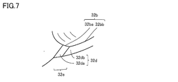
- FIG. 7 is an enlarged view of region VII in FIG.
- FIG. 8 is a perspective view of a second example of a rotary cutting tool using the cutting tool material 1 of the present disclosure.
- FIG. 9 is a perspective view of a third example of the rotary cutting tool using the cutting tool material 1 of the present disclosure.
- FIG. 10 is a cross-sectional view showing the internal oil supply structure of the rotary cutting tool of the present disclosure.
- Patent Document 1 has room for further improvement when forming attachment means for attaching to the tool carrier and brazing.
- a cutting tool material is a cutting tool material for a cutting tool that is used by being attached to a shank, and the cutting tool material is an attachment portion to the shank.
- the surface portion covers at least a part of the surface of the core portion, and the attachment structure forming portion is made of a hard material including a hard component and one or more of iron group elements.
- the hard material has a Young's modulus of 350 GPa or less
- the core portion includes a cemented carbide material
- the surface portion includes PCD (polycrystalline diamond) or CBN (cubic boron nitride)
- Hard component is W (tan Gusten), WC (tungsten carbide), TiC (titanium carbide), TiCN (titanium carbonitride), Al 2 O 3 (alumina), and at least one of CBN (cubic boron nitride) and diamond and at least one of W and WC And at least one selected from the group consisting of.
- the surface portion covers the core portion so that the core portion is not exposed to the outside.
- At least a part of the joint includes one or more of iron group elements.
- the joint between the attachment structure forming portion and the surface portion of the joint includes one or more of iron group elements.
- the core portion has a hollow portion therein, and the attachment structure forming portion has an inner core portion disposed in the hollow portion.
- the hard material has a Young's modulus of less than 300 GPa.
- the hard material has an elongation of 5% or less.
- the cutting tool material is a cutting tool material for a cutting tool that is used by being attached to a shank, and the cutting tool material is an attachment structure forming portion that serves as an attachment portion to the shank.
- a cutting structure forming portion to be a cutting blade, and a joint portion
- the cutting structure forming portion has a core portion and a surface portion provided in the attachment structure forming portion through the joint portion,
- the surface portion covers at least a part of the surface of the core portion
- the attachment structure forming portion includes a hard material containing W (tungsten), iron, and nickel, and the hard material has a Young's modulus of less than 300 GPa
- the core portion includes a cemented carbide material
- the surface portion includes CBN (cubic boron nitride)
- a method for manufacturing a cutting tool material according to another aspect of the present disclosure includes a first precursor for forming the attachment structure forming portion, a second precursor for forming the core portion, An assembly step of assembling the cutting tool material precursor using a third precursor for forming the surface portion; and a sintering step of sintering the cutting tool material precursor.
- the manufacturing method of the cutting tool material includes a second precursor and a third precursor on the first precursor via a material containing one or more of iron group elements on the first precursor.
- the body is arranged.
- a cutting tool includes a mounting portion attached to a shank, a cutting portion having a core portion and a surface portion covering the core portion around a central axis, the mounting portion, and the cutting And a joining part that joins the parts.
- the attachment portion includes a hard component and a hard material.
- the hard component is at least one of TiC (titanium carbide), TiCN (titanium carbonitride), W (tungsten), WC (tungsten carbide), Al 2 O 3 (alumina), CBN (cubic boron nitride) and diamond. And at least one selected from the group consisting of a combination of at least one of W and WC.
- the hard material contains one or more iron group elements and has a Young's modulus of 350 GPa or less.
- the core portion includes a cemented carbide material.
- the surface portion includes PCD (polycrystalline diamond) or CBN.
- the cutting part has a biting part located at an end opposite to the attachment part.
- the surface portion includes a groove, a flank, and a cutting edge constituted by a ridge line between the groove and the flank.
- the cutting edge extends from the end toward the attachment portion.
- the said flank is comprised by the biting flank located in the said biting part, and the outer periphery flank located in other than the said biting part.
- the inclination of the biting flank with respect to the central axis is greater than the inclination of the outer peripheral flank with respect to the central axis.
- the cutting edge extends from the end toward the mounting portion while rotating counterclockwise around the central axis as viewed from the end side.
- a cutting tool includes a cutting portion having an attachment portion attached to a shank, a core portion, and a surface portion covering the core portion around a central axis, the attachment portion, and the A joining portion that joins the cutting portion.
- the attachment portion includes a hard component and a hard material.
- the hard component is at least one of W (tungsten), TiC (titanium carbide), TiCN (titanium carbonitride), WC (tungsten carbide), Al 2 O 3 (alumina), CBN (cubic boron nitride), and diamond. And at least one selected from the group consisting of a combination of at least one of W and WC.
- the hard material contains one or more iron group elements and has a Young's modulus of 350 GPa or less.
- the core portion includes a cemented carbide material.
- the surface portion includes PCD (polycrystalline diamond) or CBN.
- the surface portion has a cutting edge. The cutting edge extends from an end opposite to the attachment portion toward the attachment portion while being twisted with respect to the central axis.
- the cutting edge includes a plurality of first cutting edges and a plurality of second cutting edges that are alternately arranged along a circumferential direction, and the first cutting edge is the second cutting edge. It extends while twisting with respect to the central axis in the direction opposite to the cutting edge.
- the cutting portion has a first flow path therein.
- the core portion includes a recess.
- the attachment portion has a convex portion.
- the attachment portion has a second flow path inside.
- a space located inside the cutting portion is defined by the concave portion and the convex portion.
- the first flow path connects the space and the outer peripheral surface of the cutting portion.
- the second flow path connects the space and the outside.
- FIG. 1A is a perspective view of a cutting tool material showing one embodiment of the present embodiment.
- 1B is a cross-sectional view taken along the line AA in FIG. 1A.
- 2A to 2C are cross-sectional views of a cutting tool material showing another embodiment of the present embodiment.
- FIG. 3 is a cross-sectional view of a cutting tool material showing still another embodiment of the present embodiment.
- FIG. 4 is a perspective view of a cutting tool material showing still another embodiment of the present embodiment.
- FIG. 5 is a perspective view of a cutting tool obtained from the cutting tool material 1 of the present embodiment.
- the cutting tool material 1 of the present embodiment is a material for a cutting tool that is used by being attached to the shank 5, and as shown in FIG. 1A and FIG. It has the attachment structure forming part 20, the cutting structure forming part 30 used as a cutting blade, and the junction part 40. Then, as shown in FIG. 5, the cutting part 3 and the mounting part 2 are obtained from the cutting tool material 1 by obtaining the mounting part 2 from the mounting structure forming part 20 and obtaining the cutting part 3 from the cutting structure forming part 30. A cutting tool (cutting head) 10 is obtained which is used by being attached to the shank 5 at the attachment portion 2.
- the attachment structure forming part 20 becomes the attachment part 2 for attaching to the shank 5 in the cutting tool 10 obtained by processing the cutting tool material 1 (FIG. 5).
- the attachment structure forming portion 20 is subjected to cutting or grinding.
- the attachment part 2 processed into a predetermined shape such as a screw groove or a pin hole is formed.
- the attachment structure forming portion 20 may be used as it is as the attachment portion 2, and processed into a predetermined shape as necessary as the attachment portion 2. Also good.
- the attachment structure forming portion 20 can perform cutting and grinding to form a structure for mechanical fastening such as screw fastening, pinning, other engagement, press fitting, and the like.
- the shape and size are selected so that brazing can be performed.
- the attachment structure forming portion 20 of the present embodiment has a circular shape having a joint surface with the cutting structure forming portion 30 that is the same shape as the joint surface with the attachment structure forming portion 20 of the cutting structure forming portion 30. It has a cylindrical shape that is a shape.
- FIG. 1A shows a cylindrical mounting structure forming portion 20 having a circular joint surface
- a polygonal columnar shape such as an elliptical columnar shape, a triangular prism shape or a quadrangular prism shape, or a conical shape.
- an arbitrary shape such as a polygonal pyramid shape.
- the vertical structure of the mounting structure forming portion 20 (the cross section in the vertical direction with respect to the joint surface with the cutting structure forming portion 30 and corresponding to the AA cross section in FIG. 1A) is a quadrangle.
- the joint surface of the mounting structure forming portion 20 may have the same shape and size as the joint surface of the cutting structure forming portion 30 as shown in FIG. 1B.
- the shape and size may be different from the joint surface.
- the height of the mounting structure forming portion 20 (the length in the vertical direction with respect to the joint surface with the cutting structure forming portion 30) is high enough to perform cutting and grinding to form a structure for mechanical fastening. There is no particular limitation as long as it has a height capable of brazing and has a height at which the vibration damping effect is exhibited in the mounting portion 2 obtained by processing the mounting structure forming portion 20.
- the diameter of the joint surface may be 5 mm to 30 mm and the height may be 1 mm to 20 mm.
- the attachment structure forming portion 20 is formed of a hard material containing a hard component and at least one element selected from iron group elements.
- the hard component includes at least one of W (tungsten), WC (tungsten carbide), TiC (titanium carbide), TiCN (titanium carbonitride), Al 2 O 3 (alumina), CBN (cubic boron nitride) and diamond, and W And at least one selected from the group consisting of a combination with at least one of WC.
- the iron group element is any one of cobalt, iron, and nickel. The iron group element functions as a sintering aid for converting the hard component into a sintered body.
- the hard material preferably contains W (tungsten) among the hard components, and preferably contains at least one of iron and nickel among the iron group elements.
- the hard material may contain other components such as copper as a component other than the hard component and the iron group element.
- the content of the hard component contained in the hard material is preferably 50% by mass or more, more preferably 80% by mass or more, and 90% by mass or more, based on the total mass of the hard material. Further preferred.
- the total content of iron, nickel, and cobalt contained in the hard material is preferably 50% by mass or less, more preferably 20% by mass or more, and more preferably 10% by mass or less, based on the total mass of the hard material. More preferably.
- a hard component of the mounting structure forming portion 20 W (tungsten), WC (tungsten carbide), TiC (titanium carbide), TiCN (titanium carbonitride), Al 2 O 3 (alumina), and CBN (cubic boron nitride)
- W tungsten
- WC tungsten carbide
- TiC titanium carbide
- TiCN titanium carbonitride
- Al 2 O 3 alumina
- CBN cubic boron nitride
- the brazing wettability of the mounting portion 2 when the mounting structure forming portion 20 is processed into the mounting portion 2 and brazed to the shank 5. Can be improved.
- the inventors of the present invention use the mounting portion 2 formed from the mounting structure forming portion 20 by attaching the cutting tool 10 to the shank 5 because the mounting structure forming portion 20 includes a hard material having specific physical properties.
- the present inventors have newly found that it is possible to improve the service life of the cutting tool 10 by providing a vibration damping effect that suppresses chatter and breakage when the cutting tool 10 is turned on.
- the mounting structure forming portion 20 has a smaller rigidity than the core portion 31 including a cemented carbide material and the surface portion 32 including PCD or CBN. can do.
- the attachment portion 2 to the shank 5 formed from the attachment structure forming portion 20 is also easily elastically deformed. Therefore, when using the cutting tool 10 as a rotary cutting tool, the load applied to the mounting portion 2 can be reduced, so that breakage of the cutting tool 10 can be suppressed.
- the attachment part 2 of the cutting tool 10 is easily affected by vibration when used as a rotary cutting tool, if the attachment part 2 is formed of a material that is easily deformed as described above, it is easy to absorb vibration. Therefore, it is possible to provide a rotary cutting tool having excellent vibration damping (vibration resistance) with reduced chatter.
- a hard material having a Young's modulus at a temperature of 25 ° C. of less than 500 GPa, more preferably less than 400 GPa, and 350 GPa or less. Is more preferred, and most preferred is less than 300 GPa.
- the Young's modulus is a value measured according to a tensile test.
- the attachment structure forming portion 20 and the core portion 31 and the surface portion 32 forming the cutting structure forming portion 30 are integrated by sintering.
- the mounting structure forming portion 20 including a hard material, the core portion 31 including a cemented carbide material, and the surface portion 32 including PCD or CBN are used, the inventors attach the mounting structure during the integration by the sintering. It has been found that the bondability during sintering between the structure forming part 20 and the core part 31 and the surface part 32 may deteriorate.
- the present inventors have found that by adjusting the elongation of the hard material, it is possible to suppress a decrease in bondability during sintering.
- the elongation of the hard material is preferably 5% or less, more preferably 1% or less, and further preferably 0.5% or less.
- the plastic deformability of the mounting structure forming portion 20 formed of the hard material can be reduced.
- the deformation of the attachment structure forming portion 20 due to the temperature change during sintering is reduced, so that the deformation of the attachment structure forming portion 20 and the core portion 31 and the surface portion 32 of the cutting structure forming portion 30 during sintering.
- the difference can be reduced.
- the above elongation is a value measured according to a tensile test.
- the mounting structure forming portion 20 of the present embodiment includes a hard component and an iron group element, and uses a hard material having specific physical properties to perform mechanical fastening for mounting to the shank 5. Therefore, it is possible to easily perform a cutting process or a grinding process, or brazing for mounting to the shank 5. Moreover, the vibration damping effect which suppresses chatter and breakage when the cutting tool 10 is attached to the shank 5 and used can be obtained. Then, by adjusting the elongation of the hard material, it is possible to achieve excellent bonding properties with the core portion 31 and the surface portion 32 of the cutting structure forming portion 30 during sintering.
- the Young's modulus and elongation of the hard material can be adjusted by the type and content of the hard component and the iron group element in the hard material.
- the cutting structure forming unit 30 is processed so as to form the cutting unit 3 having a cutting blade in the cutting tool 10 obtained by processing the cutting tool material 1 (FIG. 5).
- the cutting structure forming unit 30 of the present embodiment has a cylindrical shape as shown in FIG. 1A.
- size of the bottom face of the cylinder which comprises the cutting structure formation part 30, and the height of a cylinder will not be specifically limited if the cutting part 3 which has a cutting blade can be formed by cutting or grinding.
- the bottom diameter may be 5 mm to 30 mm and the height may be 5 mm to 30 mm.
- the cylindrical cutting structure forming unit 30 is shown.
- the shape is not limited to the cylindrical shape, and may be any shape such as an elliptical column shape, a polygonal column shape such as a triangular column shape or a quadrangular column shape, a conical shape or a polygonal pyramid shape.
- the shape may also be
- the cutting structure forming portion 30 has a vertical cross section (a cross section in a direction perpendicular to the joint surface with the mounting structure forming portion 20 and corresponding to the AA cross section in FIG. 1A) having a square shape.
- the joint surface of the cutting structure forming part 30 with the attachment structure forming part 20 may be the same shape / size as the joint surface of the attachment structure forming part 20 or may have a different shape / size.
- the cutting structure forming part 30 of the present embodiment has a core part 31 and a surface part 32 provided in the attachment structure forming part 20 via a joint part 40.
- the surface portion 32 covers a part of the surface of the core portion.
- the core portion 31 is provided so as to cover at least a part of the surface other than the surface in contact with the joint portion 40.
- the core part 31 and the surface part 32 are the states joined by sintering mentioned later.
- the size of the core portion 31 and the surface portion 32 may be selected so that a desired cutting blade can be cut or ground.
- the size and shape of the cutting blade to be formed, and the connection with the attachment structure forming portion 20 The diameter and height of the bottom surfaces of the core portion 31 and the surface portion 32 may be selected in consideration of the size required for the above.
- the diameter of the bottom surface of the core part 31 may be 3 mm to 27 mm, and the height of the core part 31 may be 5 mm to 30 mm.
- the outer diameter of the bottom surface of the surface portion 32 may be 5 mm to 30 mm, and the height of the surface portion 32 may be 5 mm to 30 mm.
- the core part 31 of this Embodiment is provided in the center part of the cutting structure formation part 30, as shown to FIG. 1A and FIG. 1B, and is a solid cylindrical shape.
- 1A and 1B show a solid columnar core 31, but the shape is not limited to a columnar shape, but a polygonal columnar shape such as an elliptical column shape, a triangular column shape, or a quadrangular column shape, a conical shape, or a polygonal pyramid shape.
- Arbitrary shapes, such as a shape may be sufficient, a solid shape may be sufficient, and a hollow shape may be sufficient.
- the hollow part formed in the core part 31 penetrates from the surface of the core part 31 on the side joining the attachment structure forming part 20 to the surface of the core part 31 opposite to the side joining the attachment structure forming part 20.
- the shape may be sufficient, the shape which penetrates only in any one surface among these may be sufficient, and the shape which does not penetrate in any surface may be sufficient.
- the core portion 31 has a hollow shape, as shown in FIG. 2A, the hard material that forms the attachment structure forming portion 20 in the hollow portion of the core portion 31, the material that forms the core portion 31 and the attachment structure formation portion 20
- the inner core part 33 formed with arbitrary materials, such as different steel, may be provided.
- the method of providing the inner core portion 33 is not particularly limited.
- the inner core portion 33 may be fixed to the hollow portion by screwing, shrink fitting, or brazing, in the same shape as the hollow portion of the core portion 31.
- FIG. 2A the inner core portion 33 may be fixed to the hollow portion by screwing, shrink fitting, or brazing, in the same shape as the hollow portion of the core portion 31.
- a screw is attached to the tip of the inner core portion 33 on the attachment structure forming portion 20 side so that the inner core portion 33 and the attachment structure forming portion 20 are fixed by a fixture such as a screw or a pin. You may make it make it a pin shape which provides a groove
- the inner core portion 33 made of the same material as the hard material forming the attachment structure forming portion 20 is disposed in the hollow portion of the core portion 31, it is provided in the hollow portion of the core portion 31 as shown in FIG. Assemble the mounting structure forming portion 20 and the cutting structure forming portion 30 so that the inner core portion 33 and the mounting structure forming portion 20 are integrally formed, and the inner core portion 33 is disposed in the hollow portion of the core portion 31. Also good. Thus, when the inner core portion 33 is formed integrally with the attachment structure forming portion 20 from the same material as the hard material forming the attachment structure forming portion 20, the vibration damping performance of the resulting cutting tool 10 is further improved. be able to.
- the longitudinal section of the core portion 31 and the inner core portion 33 (a section perpendicular to the joint surface with the mounting structure forming portion 20, corresponding to the section AA in FIG. 1A). ) are both rectangular, but they may be the same shape or different shapes, and the shape may be any shape such as a trapezoid or a triangle. .
- the core part 31 is formed of a cemented carbide material.
- the cemented carbide material is a material containing, for example, tungsten carbide and cobalt.
- the hardness of the core part 31 can be made smaller than the surface part 32 formed of PCD or CBN.
- the surface containing the core part 31 and PCD or CBN A good joined state with the portion 32 can be obtained.
- the content ratio of tungsten carbide and cobalt contained in the cemented carbide material forming the core portion 31 is not particularly limited, but the content of tungsten carbide is 75% by mass or more with respect to the total mass of tungsten carbide and cobalt. It is preferable that the content is 85% by mass or more. Moreover, it is preferable that content of tungsten carbide is 98 mass% or less with respect to the total mass of tungsten carbide and cobalt, and it is more preferable that it is 95 mass% or less.
- the strength of the core portion can be ensured. Moreover, it can join favorably with the surface part 32 by content of tungsten carbide being 98 mass% or less with respect to the total mass of tungsten carbide and cobalt.
- the cemented carbide material may contain other components other than tungsten carbide and cobalt.
- other components include one or more of TiC, TaC, Ni, and the like.
- the other components are preferably 10% by mass or less, and more preferably 5% by mass or less, based on the total mass of the cemented carbide material.
- the surface portion 32 of the present embodiment has a cylindrical shape having a hollow portion that accommodates the core portion 31 at the center. Then, as shown in FIG. 1B, the surface portion 32 is joined to the attachment structure forming portion 20, is provided concentrically on the outer periphery of the side surface of the cylindrical core portion 31, and has a cylindrical shape as a whole together with the core portion 31.
- the cutting structure forming part 30 is formed. The surface portion 32 is joined to the core portion 31 by sintering, which will be described later, at a portion covering the core portion 31.
- the surface portion 32 has a joint surface to be joined to the attachment structure forming portion, and is provided so as to cover at least a part of the surface of the core portion 31.
- the surface portion 32 may be provided only on the side surface portion of the surface of the core portion 31, and as shown in FIG. You may provide in the side surface and top surface of the core part 31 so that the surface may not be exposed outside.
- the cutting tool 10 which has the cutting blade formed in the surface part 32 also in the front-end
- the shape and size of the surface portion 32 are not particularly limited as long as the surface portion 32 can be bonded to the core portion 31 and the cutting structure forming portion 30 can be cut or ground to form a cutting blade. Accordingly, the surface portion 32 is formed to have an outer shape different from that of the core portion 31, and the outer shape of the cutting structure forming portion 30 is an elliptical column shape, a polygonal column shape such as a triangular column shape or a quadrangular column shape, a conical shape, You may make it form in arbitrary shapes, such as a polygonal pyramid shape.
- the cutting process or grinding process performed to form the cutting blade may be performed only on the surface part 32 or may be performed on both the surface part 32 and the core part 31. Good.
- the surface portion 32 is formed of a material containing PCD (polycrystalline diamond) or CBN (cubic boron nitride). By forming the surface portion 32 of a material containing PCD or CBN, a rotary cutting tool having excellent wear resistance and breakage resistance can be formed.
- the surface portion 32 is preferably formed of a material containing CBN.
- the joint portion 40 is formed on the joint surface between the attachment structure forming portion 20 and the cutting structure forming portion 30.
- the joint portion 40 includes at least a first joint portion that joins the joint surface of the attachment structure forming portion 20 and the core portion 31 of the cutting structure formation portion 30, a joint surface of the attachment structure formation portion 20, and a surface of the cutting structure formation portion 30. And a second joint portion that joins the portion 32.
- the thickness of the bonding portion 40 is not particularly limited as long as a required bonding strength is obtained, but may be, for example, 5 ⁇ m to 200 ⁇ m.
- the attachment structure forming portion 20 and the cutting structure forming portion 30 can be firmly joined.
- the cutting portion 3 formed from the cutting structure forming portion 30 and the mounting portion 2 formed from the mounting structure forming portion 20 are used.
- the intensity measured by the shear test of bonding portion 40 is preferably at 25 kgf / mm 2 or more, preferably 30 kgf / mm 2 or more.
- the joint part 40 is formed of a material containing one or more of iron group elements composed of cobalt, iron, and nickel. May be.
- the second joint portion that joins the attachment structure forming portion 20 and the surface portion 32 is a joint portion made of a material containing one or more of iron group elements. Bondability with the surface portion 32 of the cutting structure forming portion 30 can be improved.
- the joint portion 40 may be formed by sintering the attachment structure forming portion 20 and the cutting structure forming portion 30. Specifically, the attachment structure forming portion 20 and the core portion 31 of the cutting structure forming portion 30 are joined during sintering by an iron group element contained in the attachment structure forming portion 20 and a small amount of cobalt component contained in the core portion 31. The portion 40 can be formed. Further, even when PCD is used as the surface portion 32 of the cutting structure forming portion 30, the joint portion 40 can be formed between the mounting structure forming portion 20 and the surface portion 32 during sintering. However, when CBN having a low cobalt component content is used as the surface portion 32, deterioration in bondability is likely to be a problem.
- the bonding portion 40 including the iron group element is used. It is preferable to provide it. Thereby, the surface part 32 containing CBN and the attachment structure forming part 20 can be joined with a joining strength of 30 kgf / mm 2 or more.
- the joint 40 may include both a joint of a material containing one or more of the iron group elements and a joint formed by sintering, and includes only one of them. May be.
- the 1st junction part which joins the attachment structure formation part 20 and the core part 31 is formed by sintering
- the 2nd junction part which joins the attachment structure formation part 20 and the surface part 32 is 1 type of an iron group element Or you may form with the material containing 2 or more types.
- the cutting tool material of the present embodiment forms a first precursor to be the attachment structure forming portion 20, a second precursor to be the core portion 31, and a third precursor to be the surface portion 32. It is manufactured through an assembly process for assembling the third precursor and a sintering process for sintering the precursor of the cutting tool material assembled by the assembly process.
- Each precursor of the mounting structure forming portion 20, the core portion 31, and the surface portion 32 can be manufactured according to a conventionally known method. For example, a molded body in which raw material powder is put into a mold and press-molded, A blank processed body made into a predetermined shape by cutting or grinding from a blank material or the like can be used.
- contracts by sintering it is preferable to prepare the metal mold
- the precursor of the core portion 31 is fitted into the hollow portion of the precursor of the surface portion 32 obtained in this way by pressing to form a precursor that becomes the cutting structure forming portion 30.
- the precursor to be the cutting structure forming portion 30 is assembled in a state where the precursor of the core portion 31 and the precursor of the surface portion 32 are in contact with the precursor of the mounting structure forming portion 20, and the cutting tool material A precursor is obtained and the precursor is sintered.
- the core portion 31 and the surface portion 32 are joined, and the joint portion 40 containing cobalt is formed between the core portion 31 and the attachment structure forming portion 20.
- a joint 40 containing cobalt is formed between the surface portion 32 and the attachment structure forming portion 20.
- the precursor of the core portion 31 and the precursor of the attachment structure forming portion 20 are interposed on the precursor containing one or more of iron group elements composed of nickel, iron, and cobalt.
- the precursor of the surface portion 32 is disposed and sintered, the joint portion 40 containing the iron group element is formed.
- the material containing an iron group element may be arranged in a powder form or a foil form between the precursors.
- the sintering process may be performed under conditions known in the art, but in the present embodiment, different materials are used for the attachment structure forming portion 20, the core portion 31, and the surface portion 32, respectively. Degree of deformation is different. Due to this difference in deformation, there is a possibility that cracks may occur at the portions where the molded bodies forming the attachment structure forming portion 20, the core portion 31, and the surface portion 32 are in contact with each other. Therefore, in the sintering process, after sintering under conditions of pressure 4.5 GPa to 7.5 GPa and temperature 1200 to 1700 ° C., the pressure is reduced to 3 GPa to 4 GPa while maintaining the temperature, and the core portion 31 is compressed. , Release the pressure to normal pressure, and bring the temperature to room temperature. Thereby, it is possible to obtain good jointability at the portion where the respective molded bodies are in contact with each other without causing cracks at the portions where the respective molded bodies are in contact with each other.
- the cutting tool material of the present disclosure can be suitably used as a cutting tool 10 of a rotary cutting tool such as a drill or an end mill as shown in FIG.
- test piece As a test piece, a strip shape having a length of 30 mm and a width of 5 mm is prepared, and the test piece is subjected to a tensile test at a tensile speed of 0.1 mm / min using an autograph (manufactured by Shimadzu Corporation), and a strain gauge method is used. Young's modulus and elongation were measured.
- A The value measured with a vibrometer was small (less than 1.5 m / s 2 ), and the vibration damping property when using a rotary cutting tool was very excellent.
- Example 1 First, in order to form the cylindrical mounting structure forming portion 20, the cylindrical core portion 31, and the hollow cylindrical surface portion 32 shown in FIGS. 1A and 1B by sintering, using the following powder materials, It was press-molded with a mold to obtain a molded body for an attachment structure forming portion, a molded body for a core portion, and a molded body for a surface portion.
- -Molding for mounting structure molded part Material Hard material containing 90% by mass of tungsten and 10% by mass of metal binder containing iron, nickel and copper (Young's modulus: 280 GPa, elongation 0.4%) -Molded body for core material: Powder of cemented carbide containing 94% by mass of tungsten carbide and 6% by mass of cobalt Pressure during press molding: 100MPa to 200MPa -Molded body for surface portion Powder material: Powder of material containing CBN and inevitable impurities Pressure during press molding: 100 MPa to 200 MPa Next, the core part molded body was fitted into the hollow part of the surface part molded body obtained as described above by pressing to obtain a cutting structure forming part molded body.
- a nickel 100% by mass thin plate is disposed on the joint surface of the mounting structure forming portion molded body to form the joint portion 40, and the core portion molded body and the surface portion molded body are disposed on the thin plate. And each said molded object was assembled.
- the molded body assembled as described above was sintered under conditions of a temperature of 1400 ° C. and a pressure of 5 Pa to obtain a cutting tool material 1.
- the size of the obtained cutting tool material 1 is 8 mm in diameter and 20 mm in height, the height of the mounting structure forming portion 20 is 12 mm, the diameter of the core portion 31 is 5 mm, and the thickness of the surface portion 32 in the circumferential direction.
- the height of the core portion 31 and the surface portion 32 was 5 mm.
- the cutting structure forming portion 30 of the obtained cutting tool material 1 is formed with a cutting blade having four blades (twisting angle is 45 °), a screw groove is formed in the mounting structure forming portion 20, and the diameter is 7.5 mm.
- a rotary cutting tool was obtained by fastening with a screw of a cemented carbide shank 5 having a length of 75 mm. The obtained rotary cutting tool was evaluated for vibration and breakage during the rotary cutting operation. The results are shown in Table 1.
- Example 1 Example except that the cemented carbide material (Young's modulus: 620 GPa, elongation 0.5%) used as the material for the core part molded body in Example 1 was used as the material for the molded part for the mounting structure molded part.
- the raw material for cutting tools and the rotary cutting tool were obtained in the same manner as in 1.
- the obtained rotary cutting tool was evaluated for vibration and breakage during the rotary cutting operation. The results are shown in Table 1.
- Example 1 From a comparison between Example 1 and Comparative Example 1, it was found that by forming the attachment structure forming portion with a hard material, the vibration damping performance during the rotary cutting operation was excellent and breakage could be suppressed.
- Example 2 A cutting tool material and a rotary cutting tool were obtained in the same manner as in Example 1 except that the following materials were used as the material for the mounting structure molded part.
- -Molded body for mounting structure molded part material of Example 2
- Hard material containing 95% by mass of tungsten and 5% by mass of a metal binder containing iron, nickel and copper Youngng's modulus: 300 GPa, 5% elongation
- (Material of Example 3) A hard material containing 95% by mass of tungsten and 5% by mass of a metal binder containing iron, nickel, and copper (Young's modulus: 350 GPa, elongation: 25%)
- the obtained rotary cutting tool was evaluated for vibration and breakage during the rotary cutting operation. The results are shown in Table 1.
- Example 3 From the comparison of Example 1 to Example 3, it was found that the smaller the Young's modulus of the mounting structure molding portion, the better the vibration damping property of the obtained rotary cutting tool and the prevention of breakage.
- FIG. 6 is a perspective view of a first example of a rotary cutting tool using the cutting tool material 1 of the present disclosure.
- FIG. 7 is an enlarged view of region VII in FIG.
- the rotary cutting tool according to the first example is a reamer.
- the rotary cutting tool according to the first example is formed using the cutting tool material 1 of the present disclosure. Therefore, a cutting edge can be formed at any position on the outer peripheral surface 32a, and the cutting tool can have a small diameter and a large number of cutting edges.
- the rotary cutting tool according to the first example has a cutting tool 10.
- the cutting tool 10 has an attachment part 2 and a cutting part 3.
- the attachment portion 2 and the cutting portion 3 are joined by the joint portion 40.
- the attachment part 2 is detachably attached to the shank 5.
- the cutting part 3 includes the core part 31 and the surface part 32, and the surface part 32 covers the outer peripheral surface of the core part 31. From another point of view, the surface portion 32 covers the surface of the core portion 31 around the central axis.
- the attaching part 2 and the cutting part 3 are formed by processing the cutting tool raw material 1 of this indication.
- the surface portion 32 has an outer peripheral surface 32a.
- the outer peripheral surface 32 a is the outer peripheral surface of the cutting part 3.
- the outer peripheral surface 32a has a cutting edge 32b, a groove 32c, and a flank 32d.
- the surface portion 32 has a biting portion 32e.
- the cutting edge 32b is formed on the outer peripheral surface 32a. Note that the cutting edge 32b may be formed not only on the outer peripheral surface 32a but also on other portions (for example, the attachment portion 2, the core portion 31, and the joint portion 40). It is preferable that a plurality of cutting edges 32b are provided.
- the cutting edge 32b is preferably twisted counterclockwise with respect to the central axis A. Note that the cutting edge 32b is twisted counterclockwise with respect to the central axis A when the cutting edge 32b is viewed from the tip of the rotary cutting tool (the end opposite to the mounting part 2 side of the cutting part 3). In addition, it means that the cutting edge 32b extends toward the mounting portion 2 while rotating counterclockwise around the central axis A.
- the cutting edge 32b may not be twisted. That is, the cutting edge 32b may be formed linearly.
- the outer peripheral surface 32a is recessed.
- a cutting edge 32b is constituted by a ridge line between the groove 32c and the flank 32d. That is, the groove 32c located on the side of the cutting edge 32b is a rake face.
- the biting portion 32e is a portion that bites the work material and mainly performs cutting.
- the biting portion 32e is disposed at the tip of the surface portion 32 (the end opposite to the attachment portion 2 side of the cutting portion 3).
- the flank 32d has a biting flank 32da and an outer peripheral flank 32db.
- the biting flank 32da is a flank 32d located at the biting portion 32e.
- the outer peripheral flank 32db is a flank 32d positioned other than the biting portion 32e.
- the flank 32d is chamfered at the chamfered portion 32e, and the chamfered flank 32da is formed by this chamfering. That is, by performing this chamfering, a chamfered flank 32da that is inclined more than the outer peripheral flank 32db with respect to the central axis is formed.
- the inclination with respect to the central axis A of the biting flank 32da is larger than the inclination with respect to the central axis A of the outer peripheral flank 32db. More specifically, the biting flank 32da is inclined so that the distance from the central axis A becomes closer as it approaches the tip of the surface portion 32.
- the cutting edge 32b has a chamfering cutting edge 32ba and an outer peripheral cutting edge 32bb.
- the biting edge 32ba is a cutting edge 32b located in the biting portion 32e.
- the outer peripheral cutting edge 32bb is a cutting edge 32b positioned other than the biting portion 32e.
- biting edge 32ba is formed by a ridge line between the biting flank 32da and the groove 32c.
- the outer peripheral cutting edge 32bb is formed by a ridge line between the outer peripheral flank 32db and the groove 32c.
- FIG. 8 is a perspective view of a second example of a rotary cutting tool using the cutting tool material 1 of the present disclosure.
- FIG. 9 is a perspective view of a third example of the rotary cutting tool using the cutting tool material 1 of the present disclosure.
- the rotary cutting tool according to the second example is a T-slot cutter.
- the rotary cutting tool according to the third example is also a T slot cutter.
- the cutting tool according to the second and third examples has a cutting tool 10.
- the cutting tool 10 has an attachment part 2 and a cutting part 3. Although not shown, as described above, the attachment portion 2 and the cutting portion 3 are joined by the joint portion 40.
- the attachment part 2 is detachably attached to the shank 5.
- the cutting part 3 includes the core part 31 and the surface part 32 as described above.
- the surface portion 32 of the cutting tool material 1 of the present disclosure has an outer peripheral surface 32a.
- the outer peripheral surface 32a has a first cutting edge 32bc, a second cutting edge 32bd, and a groove 32c.
- a plurality of first cutting edges 32bc and second cutting edges 32bd may be provided.
- the first cutting edges 32bc and the second cutting edges 32bd are alternately arranged along the circumferential direction on the outer peripheral surface 32a.
- the groove 32c is disposed between the first cutting edge 32bc and the second cutting edge 32bd.
- 1st cutting edge 32bc and 2nd cutting edge 32bd are extended toward the attachment part 2 from the front-end
- the first cutting edge 32bc and the second cutting edge 32bd may be twisted in the same direction.
- the first cutting edge 32bc may extend while twisting in the direction opposite to the second cutting edge 32bd.
- the first cutting edge 32bc may be twisted clockwise with respect to the central axis
- the second cutting edge 32bd may be twisted counterclockwise with respect to the central axis. That is, the first cutting edge 32bc and the second cutting edge 32bd may be formed in a staggered shape.
- FIG. 10 is a cross-sectional view showing the internal oil supply structure of the rotary cutting tool of the present disclosure.
- the rotary cutting tool has an attachment portion 2, a cutting portion 3, and a joint portion 40.
- the cutting part 3 has a core part 31 and a surface part 32.
- the core part 31 has the recessed part 31a.
- the concave portion 31 a is provided on the surface of the core portion 31 on the mounting portion 2 side.
- the attachment part 2 has a convex part 2a.
- the convex portion 2 a is provided on the surface of the attachment portion 2 on the cutting portion 3 side.
- the attachment portion 2 is joined to the cutting portion 3 by the joint portion 40 in a state where the convex portion 2a is inserted into the concave portion 31a.
- the depth of the concave portion 31a is larger than the height of the convex portion 2a. Therefore, a space 31 b is formed between the attachment portion 2 and the core portion 31. That is, a space 31b defined by the convex portion 2a and the concave portion 31a is formed inside the cutting portion 3.
- the cutting unit 3 has a first flow path 34. There may be a plurality of first flow paths 34.
- the first flow path 34 is connected to the space 31b at one end.
- the first flow path 34 is connected to the outer peripheral surface of the cutting part 3 at the other end.
- the first flow path 34 penetrates the core portion 31 and the surface portion 32.
- the rotary cutting tool of the present disclosure further has a second flow path 6.
- the second flow path 6 is formed inside the attachment portion 2.
- the second flow path 6 is connected to the space 31b at one end.
- the second flow path 6 is connected to the outside of the rotary cutting tool of the present disclosure at the other end.
- the cutting oil When the cutting oil is supplied from the other end of the second flow path 6, the cutting oil is supplied to the space 31b through the second flow path 6 and accumulates in the space 31b.
- the cutting oil that has accumulated in the space 31 b is supplied to the outer peripheral surface of the cutting structure forming unit 30 via the other end of the first flow path 34.
- the space 31b functions as an oil reservoir
- the first channel 34 functions as an oil supply port to the cutting edge
- the second channel 6 functions as an oil hole.
Landscapes
- Engineering & Computer Science (AREA)
- Mechanical Engineering (AREA)
- Manufacturing & Machinery (AREA)
- Chemical & Material Sciences (AREA)
- Materials Engineering (AREA)
- Organic Chemistry (AREA)
- Composite Materials (AREA)
- Metallurgy (AREA)
- Cutting Tools, Boring Holders, And Turrets (AREA)
- Drilling Tools (AREA)
- Chemical Kinetics & Catalysis (AREA)
- Milling Processes (AREA)
- Milling, Broaching, Filing, Reaming, And Others (AREA)
Abstract
Priority Applications (6)
| Application Number | Priority Date | Filing Date | Title |
|---|---|---|---|
| CN201680090839.6A CN109996632B (zh) | 2016-11-15 | 2016-11-15 | 切削工具 |
| KR1020197013520A KR102188627B1 (ko) | 2016-11-15 | 2016-11-15 | 절삭 공구 |
| US16/062,686 US10293411B2 (en) | 2016-11-15 | 2016-11-15 | Cutting tool |
| PCT/JP2016/083803 WO2018092187A1 (fr) | 2016-11-15 | 2016-11-15 | Outil de coupe |
| JP2018550895A JP6629990B2 (ja) | 2016-11-15 | 2016-11-15 | 切削工具 |
| EP16921956.5A EP3542934B1 (fr) | 2016-11-15 | 2016-11-15 | Alesoir |
Applications Claiming Priority (1)
| Application Number | Priority Date | Filing Date | Title |
|---|---|---|---|
| PCT/JP2016/083803 WO2018092187A1 (fr) | 2016-11-15 | 2016-11-15 | Outil de coupe |
Publications (1)
| Publication Number | Publication Date |
|---|---|
| WO2018092187A1 true WO2018092187A1 (fr) | 2018-05-24 |
Family
ID=62146361
Family Applications (1)
| Application Number | Title | Priority Date | Filing Date |
|---|---|---|---|
| PCT/JP2016/083803 Ceased WO2018092187A1 (fr) | 2016-11-15 | 2016-11-15 | Outil de coupe |
Country Status (6)
| Country | Link |
|---|---|
| US (1) | US10293411B2 (fr) |
| EP (1) | EP3542934B1 (fr) |
| JP (1) | JP6629990B2 (fr) |
| KR (1) | KR102188627B1 (fr) |
| CN (1) | CN109996632B (fr) |
| WO (1) | WO2018092187A1 (fr) |
Cited By (1)
| Publication number | Priority date | Publication date | Assignee | Title |
|---|---|---|---|---|
| CN110480014A (zh) * | 2019-08-20 | 2019-11-22 | 扬州海昌新材股份有限公司 | 以粉末为原料生产多功能外圆倒角刀方法 |
Families Citing this family (7)
| Publication number | Priority date | Publication date | Assignee | Title |
|---|---|---|---|---|
| EP3375554B1 (fr) * | 2016-11-15 | 2021-05-19 | Sumitomo Electric Hardmetal Corp. | Outil de coupe |
| JP7313599B2 (ja) * | 2019-03-27 | 2023-07-25 | 三菱マテリアル株式会社 | 硬質焼結体用の基材、硬質焼結体および切削工具 |
| DE102020112808A1 (de) * | 2020-05-12 | 2021-11-18 | Kennametal Inc. | Schneidwerkzeug und Verfahren zur Herstellung eines Schneidwerkzeugs |
| KR102220310B1 (ko) * | 2020-07-21 | 2021-02-25 | (주)신성금속 | 리머 |
| WO2023074924A1 (fr) * | 2021-10-25 | 2023-05-04 | 한국생산기술연구원 | Outil de coupe capable d'ajuster la rigidité et l'atténuation |
| CN116250678B (zh) * | 2023-03-09 | 2024-12-03 | 韵斐诗化妆品(上海)有限公司 | 可替换切削膏管 |
| CN117300262A (zh) * | 2023-10-10 | 2023-12-29 | 北京沃尔德金刚石工具股份有限公司 | 一种整头多刃pcd铰刀及其加工工艺 |
Citations (6)
| Publication number | Priority date | Publication date | Assignee | Title |
|---|---|---|---|---|
| JP2001252817A (ja) * | 2000-03-09 | 2001-09-18 | Hitachi Tool Engineering Ltd | 刃部交換式切削工具 |
| JP2001252808A (ja) * | 2000-03-09 | 2001-09-18 | Hitachi Tool Engineering Ltd | 刃部交換式ドリル |
| JP2004218048A (ja) * | 2003-01-17 | 2004-08-05 | Kyocera Corp | 複合硬質焼結体およびこれを用いた複合部材、切削工具 |
| WO2009126521A2 (fr) * | 2008-04-11 | 2009-10-15 | Kennametal Inc. | Trépan tranchant utile pour impacter des strates terrestres |
| JP2011056594A (ja) * | 2009-09-07 | 2011-03-24 | Dijet Industrial Co Ltd | 切削工具 |
| WO2016178626A1 (fr) * | 2015-05-07 | 2016-11-10 | Atlas Copco Secoroc Ab | Outil de coupe |
Family Cites Families (58)
| Publication number | Priority date | Publication date | Assignee | Title |
|---|---|---|---|---|
| US692749A (en) * | 1901-07-17 | 1902-02-04 | Georgia White | Power-transmitter and speed-controller. |
| US3085453A (en) * | 1960-05-27 | 1963-04-16 | Carl W Mossberg | Method of preforming a coolant type drill |
| JPS60127810U (ja) * | 1984-02-06 | 1985-08-28 | 住友電気工業株式会社 | 超硬切削工具 |
| JPS60238214A (ja) * | 1984-05-10 | 1985-11-27 | Toshiba Tungaloy Co Ltd | 回転切削工具 |
| DE3575092D1 (de) * | 1984-06-12 | 1990-02-08 | Sumitomo Electric Industries | Stab aus verbundmaterialien und verfahren zu seiner herstellung. |
| JPH02106210A (ja) * | 1988-10-14 | 1990-04-18 | Sumitomo Electric Ind Ltd | ねじれ刃多結晶ダイヤモンド工具及びその製造方法 |
| JPH0343112A (ja) * | 1989-07-07 | 1991-02-25 | Sumitomo Electric Ind Ltd | 焼結硬質合金製ドリル |
| JP2556393B2 (ja) * | 1990-02-07 | 1996-11-20 | ジーエヌツール株式会社 | ねじれ刃を有する切削工具及びその製造方法 |
| US5020780A (en) * | 1990-04-04 | 1991-06-04 | Woodings Industrial Corporation | Quick connect-disconnect coupling for blast furnace tap hole drill bit |
| JPH0413506A (ja) * | 1990-04-27 | 1992-01-17 | Sumitomo Electric Ind Ltd | ダイヤモンド被覆Si↓3N↓4焼結体製マイクロドリル |
| US5031484A (en) * | 1990-05-24 | 1991-07-16 | Smith International, Inc. | Diamond fluted end mill |
| US5070748A (en) * | 1990-05-24 | 1991-12-10 | Smith International, Inc. | Diamond fluted end mill |
| GB2259263B (en) * | 1991-08-08 | 1995-11-22 | Habit Diamond Ltd | Wear resistant tools |
| GB9220671D0 (en) * | 1992-10-01 | 1992-11-11 | Hunt James G | Disposable cutting head gun reamer |
| JPH0724620A (ja) * | 1993-06-30 | 1995-01-27 | Retsu Gomi | エンドミル |
| US5443337A (en) * | 1993-07-02 | 1995-08-22 | Katayama; Ichiro | Sintered diamond drill bits and method of making |
| US5685671A (en) * | 1993-11-01 | 1997-11-11 | Smith International, Inc. | Diamond or CBN fluted center cutting end mill |
| SE509207C2 (sv) * | 1995-05-04 | 1998-12-14 | Seco Tools Ab | Verktyg för skärande bearbetning |
| AU2587095A (en) * | 1995-05-11 | 1996-11-29 | Smith International, Inc. | Diamond or cbn fluted center cutting end mill |
| JPH08336716A (ja) * | 1995-06-13 | 1996-12-24 | Asahi Daiyamondo Kogyo Kk | 回転切削工具 |
| US5716170A (en) * | 1996-05-15 | 1998-02-10 | Kennametal Inc. | Diamond coated cutting member and method of making the same |
| SE511429C2 (sv) * | 1996-09-13 | 1999-09-27 | Seco Tools Ab | Verktyg, skärdel, verktygskropp för skärande bearbetning samt metod för montering av skärdel till verktygskropp |
| SE509931C2 (sv) * | 1996-09-27 | 1999-03-22 | Seco Tools Ab | Pinnfräs, pinnfräshuvud samt metod för montering av ett lösbart pinnfräshuvud på ett skaft till en pinnfräs |
| US5701578A (en) * | 1996-11-20 | 1997-12-23 | Kennametal Inc. | Method for making a diamond-coated member |
| JP3690626B2 (ja) * | 1997-08-19 | 2005-08-31 | 株式会社アライドマテリアル | ダイヤモンドコーティングドリルおよびエンドミル及びその製造方法 |
| JP2000296410A (ja) * | 1999-04-13 | 2000-10-24 | Honda Motor Co Ltd | 複合材製エンドミル |
| SE9903685L (sv) * | 1999-10-14 | 2001-04-15 | Seco Tools Ab | Verktyg för roterande skärande bearbetning, verktygsspets samt metod för tillverkning av verktygsspetsen |
| US6511265B1 (en) * | 1999-12-14 | 2003-01-28 | Ati Properties, Inc. | Composite rotary tool and tool fabrication method |
| JP3720010B2 (ja) * | 2002-10-02 | 2005-11-24 | オーエスジー株式会社 | 深穴加工用ドリル |
| JP4145629B2 (ja) * | 2002-11-11 | 2008-09-03 | 住友電工ハードメタル株式会社 | マイクロドリル |
| US20050133277A1 (en) * | 2003-08-28 | 2005-06-23 | Diamicron, Inc. | Superhard mill cutters and related methods |
| JP4854946B2 (ja) * | 2004-09-30 | 2012-01-18 | 三菱マテリアル株式会社 | エンドミル素材及びエンドミル |
| DE102005047510A1 (de) * | 2005-10-04 | 2007-04-05 | Gühring Ohg | Spanabtragendes Werkzeug |
| JP2007185736A (ja) * | 2006-01-12 | 2007-07-26 | Sumitomo Electric Hardmetal Corp | エンドミル |
| DE102006000251A1 (de) * | 2006-05-30 | 2007-12-06 | Hilti Ag | Hartstoffkopf und Drehschlagbohrer |
| JP2008049409A (ja) * | 2006-08-22 | 2008-03-06 | Sumitomo Electric Hardmetal Corp | ボールエンドミルおよびその製造方法 |
| JP4464953B2 (ja) * | 2006-11-30 | 2010-05-19 | ユニオンツール株式会社 | 切削工具及びその製造方法 |
| US20090142150A1 (en) * | 2007-11-29 | 2009-06-04 | Yang Tsuan Chu | Tungsten steel cutter |
| JP5382463B2 (ja) * | 2008-02-29 | 2014-01-08 | マニー株式会社 | 歯科用切削具 |
| FR2935914B1 (fr) * | 2008-09-16 | 2012-07-27 | Sarl Fac | Outil de coupe plat et porte-outil associe. |
| GB0819257D0 (en) * | 2008-10-21 | 2008-11-26 | Element Six Holding Gmbh | Insert for an attack tool |
| US8272816B2 (en) * | 2009-05-12 | 2012-09-25 | TDY Industries, LLC | Composite cemented carbide rotary cutting tools and rotary cutting tool blanks |
| JP5071462B2 (ja) | 2009-09-18 | 2012-11-14 | 日立ツール株式会社 | 回転切削工具 |
| US9358079B2 (en) * | 2010-02-11 | 2016-06-07 | Sybron Canada Lp | Bur and method of making same |
| JP5168597B2 (ja) * | 2010-02-12 | 2013-03-21 | 住友電工ハードメタル株式会社 | ヘッド着脱式切削工具 |
| GB201010061D0 (en) * | 2010-06-16 | 2010-07-21 | Element Six Ltd | Rotary machine tools |
| JP5488374B2 (ja) * | 2010-09-29 | 2014-05-14 | 三菱マテリアル株式会社 | ヘッド交換式切削工具 |
| CN103370156A (zh) * | 2011-02-23 | 2013-10-23 | 京瓷株式会社 | 切削工具及其制造方法 |
| JP2012254486A (ja) * | 2011-06-07 | 2012-12-27 | Tomei Diamond Co Ltd | 超高圧焼結体回転切削工具 |
| US9555506B2 (en) * | 2012-02-28 | 2017-01-31 | Kyocera Corporation | Drill blank, method for manufacturing drill blank, drill, and method for manufacturing drill |
| GB201206965D0 (en) * | 2012-04-20 | 2012-06-06 | Element Six Abrasives Sa | Super-hard constructions and mathod for making same |
| FR3006215B1 (fr) * | 2013-05-29 | 2015-10-09 | Mecachrome France | Outil coupant rotatif presentant une arete en plusieurs materiaux. |
| US20150061236A1 (en) * | 2013-08-30 | 2015-03-05 | Topgreen Technology Co., Ltd. | Soldered machining tool and soldered bar stock for forming the soldered machining tool |
| DE102014207502B4 (de) * | 2014-04-17 | 2022-11-24 | Kennametal Inc. | Rotationswerkzeug sowie Werkzeugkopf |
| JP2015205329A (ja) * | 2014-04-22 | 2015-11-19 | オーエスジー株式会社 | 超硬合金と鋼材とを接合した切削工具およびその切削工具の製造方法 |
| RU2017133614A (ru) * | 2015-02-28 | 2019-03-28 | Элемент Сикс (Юк) Лимитид | Сверхтвердые конструкции и способы их получения |
| US20160263666A1 (en) * | 2015-03-12 | 2016-09-15 | Kennametal Inc. | Cutting member with coolant delivery |
| US10702926B2 (en) * | 2016-10-07 | 2020-07-07 | Sumitomo Electric Hardmetal Corp. | Rotary cutting blade material and method for manufacturing the same |
-
2016
- 2016-11-15 KR KR1020197013520A patent/KR102188627B1/ko active Active
- 2016-11-15 JP JP2018550895A patent/JP6629990B2/ja active Active
- 2016-11-15 WO PCT/JP2016/083803 patent/WO2018092187A1/fr not_active Ceased
- 2016-11-15 EP EP16921956.5A patent/EP3542934B1/fr active Active
- 2016-11-15 CN CN201680090839.6A patent/CN109996632B/zh active Active
- 2016-11-15 US US16/062,686 patent/US10293411B2/en active Active
Patent Citations (6)
| Publication number | Priority date | Publication date | Assignee | Title |
|---|---|---|---|---|
| JP2001252817A (ja) * | 2000-03-09 | 2001-09-18 | Hitachi Tool Engineering Ltd | 刃部交換式切削工具 |
| JP2001252808A (ja) * | 2000-03-09 | 2001-09-18 | Hitachi Tool Engineering Ltd | 刃部交換式ドリル |
| JP2004218048A (ja) * | 2003-01-17 | 2004-08-05 | Kyocera Corp | 複合硬質焼結体およびこれを用いた複合部材、切削工具 |
| WO2009126521A2 (fr) * | 2008-04-11 | 2009-10-15 | Kennametal Inc. | Trépan tranchant utile pour impacter des strates terrestres |
| JP2011056594A (ja) * | 2009-09-07 | 2011-03-24 | Dijet Industrial Co Ltd | 切削工具 |
| WO2016178626A1 (fr) * | 2015-05-07 | 2016-11-10 | Atlas Copco Secoroc Ab | Outil de coupe |
Non-Patent Citations (1)
| Title |
|---|
| See also references of EP3542934A4 * |
Cited By (2)
| Publication number | Priority date | Publication date | Assignee | Title |
|---|---|---|---|---|
| CN110480014A (zh) * | 2019-08-20 | 2019-11-22 | 扬州海昌新材股份有限公司 | 以粉末为原料生产多功能外圆倒角刀方法 |
| CN110480014B (zh) * | 2019-08-20 | 2022-02-18 | 扬州海昌新材股份有限公司 | 以粉末为原料生产多功能外圆倒角刀方法 |
Also Published As
| Publication number | Publication date |
|---|---|
| CN109996632B (zh) | 2020-09-01 |
| JP6629990B2 (ja) | 2020-01-15 |
| KR102188627B1 (ko) | 2020-12-08 |
| US20180369924A1 (en) | 2018-12-27 |
| US10293411B2 (en) | 2019-05-21 |
| EP3542934A4 (fr) | 2020-06-10 |
| EP3542934A1 (fr) | 2019-09-25 |
| CN109996632A (zh) | 2019-07-09 |
| JPWO2018092187A1 (ja) | 2019-10-10 |
| EP3542934B1 (fr) | 2024-04-24 |
| KR20190069475A (ko) | 2019-06-19 |
Similar Documents
| Publication | Publication Date | Title |
|---|---|---|
| WO2018092187A1 (fr) | Outil de coupe | |
| JP6614541B2 (ja) | 回転切削刃用素材及びその製造方法 | |
| US9393629B2 (en) | Cutter elements, rotary machine tools comprising same and method for making same | |
| US9844814B2 (en) | Superhard tool tip, method for making same and tool comprising same | |
| CN103930227B (zh) | 多件式麻花钻头头部和包括其的麻花钻头 | |
| US9975185B2 (en) | Twist drill tips, precursor constructions for use in making same, and methods for making and using same | |
| KR20100034736A (ko) | 다조각 공구 조립체 및 절삭 공구 | |
| JP2006510492A (ja) | 深穴用ドリル | |
| US9421611B2 (en) | Composite cutting insert and method of making same | |
| JP5743868B2 (ja) | 切削工具 | |
| JP2013094857A (ja) | 切削チップおよび内径加工用切削工具 |
Legal Events
| Date | Code | Title | Description |
|---|---|---|---|
| 121 | Ep: the epo has been informed by wipo that ep was designated in this application |
Ref document number: 16921956 Country of ref document: EP Kind code of ref document: A1 |
|
| ENP | Entry into the national phase |
Ref document number: 2018550895 Country of ref document: JP Kind code of ref document: A |
|
| ENP | Entry into the national phase |
Ref document number: 20197013520 Country of ref document: KR Kind code of ref document: A |
|
| NENP | Non-entry into the national phase |
Ref country code: DE |
|
| ENP | Entry into the national phase |
Ref document number: 2016921956 Country of ref document: EP Effective date: 20190617 |