WO2018092588A1 - 車両用懸架装置 - Google Patents
車両用懸架装置 Download PDFInfo
- Publication number
- WO2018092588A1 WO2018092588A1 PCT/JP2017/039527 JP2017039527W WO2018092588A1 WO 2018092588 A1 WO2018092588 A1 WO 2018092588A1 JP 2017039527 W JP2017039527 W JP 2017039527W WO 2018092588 A1 WO2018092588 A1 WO 2018092588A1
- Authority
- WO
- WIPO (PCT)
- Prior art keywords
- vehicle body
- vehicle
- coil spring
- damper
- knuckle
- Prior art date
- Legal status (The legal status is an assumption and is not a legal conclusion. Google has not performed a legal analysis and makes no representation as to the accuracy of the status listed.)
- Ceased
Links
Images


Classifications
-
- B—PERFORMING OPERATIONS; TRANSPORTING
- B60—VEHICLES IN GENERAL
- B60G—VEHICLE SUSPENSION ARRANGEMENTS
- B60G11/00—Resilient suspensions characterised by arrangement, location or kind of springs
- B60G11/14—Resilient suspensions characterised by arrangement, location or kind of springs having helical, spiral or coil springs only
- B60G11/16—Resilient suspensions characterised by arrangement, location or kind of springs having helical, spiral or coil springs only characterised by means specially adapted for attaching the spring to axle or sprung part of the vehicle
-
- B—PERFORMING OPERATIONS; TRANSPORTING
- B60—VEHICLES IN GENERAL
- B60G—VEHICLE SUSPENSION ARRANGEMENTS
- B60G3/00—Resilient suspensions for a single wheel
- B60G3/02—Resilient suspensions for a single wheel with a single pivoted arm
- B60G3/04—Resilient suspensions for a single wheel with a single pivoted arm the arm being essentially transverse to the longitudinal axis of the vehicle
- B60G3/06—Resilient suspensions for a single wheel with a single pivoted arm the arm being essentially transverse to the longitudinal axis of the vehicle the arm being rigid
-
- B—PERFORMING OPERATIONS; TRANSPORTING
- B60—VEHICLES IN GENERAL
- B60G—VEHICLE SUSPENSION ARRANGEMENTS
- B60G15/00—Resilient suspensions characterised by arrangement, location or type of combined spring and vibration damper, e.g. telescopic type
- B60G15/02—Resilient suspensions characterised by arrangement, location or type of combined spring and vibration damper, e.g. telescopic type having mechanical spring
- B60G15/06—Resilient suspensions characterised by arrangement, location or type of combined spring and vibration damper, e.g. telescopic type having mechanical spring and fluid damper
- B60G15/062—Resilient suspensions characterised by arrangement, location or type of combined spring and vibration damper, e.g. telescopic type having mechanical spring and fluid damper the spring being arranged around the damper
- B60G15/063—Resilient suspensions characterised by arrangement, location or type of combined spring and vibration damper, e.g. telescopic type having mechanical spring and fluid damper the spring being arranged around the damper characterised by the mounting of the spring on the damper
-
- B—PERFORMING OPERATIONS; TRANSPORTING
- B60—VEHICLES IN GENERAL
- B60G—VEHICLE SUSPENSION ARRANGEMENTS
- B60G3/00—Resilient suspensions for a single wheel
- B60G3/02—Resilient suspensions for a single wheel with a single pivoted arm
- B60G3/04—Resilient suspensions for a single wheel with a single pivoted arm the arm being essentially transverse to the longitudinal axis of the vehicle
-
- B—PERFORMING OPERATIONS; TRANSPORTING
- B60—VEHICLES IN GENERAL
- B60G—VEHICLE SUSPENSION ARRANGEMENTS
- B60G7/00—Pivoted suspension arms; Accessories thereof
- B60G7/02—Attaching arms to sprung part of vehicle
-
- B—PERFORMING OPERATIONS; TRANSPORTING
- B62—LAND VEHICLES FOR TRAVELLING OTHERWISE THAN ON RAILS
- B62D—MOTOR VEHICLES; TRAILERS
- B62D7/00—Steering linkage; Stub axles or their mountings
- B62D7/16—Arrangement of linkage connections
- B62D7/166—Arrangement of linkage connections substantially perpendicular, e.g. between tie-rod and steering knuckle
-
- B—PERFORMING OPERATIONS; TRANSPORTING
- B60—VEHICLES IN GENERAL
- B60G—VEHICLE SUSPENSION ARRANGEMENTS
- B60G2200/00—Indexing codes relating to suspension types
- B60G2200/10—Independent suspensions
- B60G2200/14—Independent suspensions with lateral arms
- B60G2200/142—Independent suspensions with lateral arms with a single lateral arm, e.g. MacPherson type
- B60G2200/1424—Independent suspensions with lateral arms with a single lateral arm, e.g. MacPherson type the lateral arm having an L-shape
-
- B—PERFORMING OPERATIONS; TRANSPORTING
- B60—VEHICLES IN GENERAL
- B60G—VEHICLE SUSPENSION ARRANGEMENTS
- B60G2200/00—Indexing codes relating to suspension types
- B60G2200/40—Indexing codes relating to the wheels in the suspensions
- B60G2200/44—Indexing codes relating to the wheels in the suspensions steerable
-
- B—PERFORMING OPERATIONS; TRANSPORTING
- B60—VEHICLES IN GENERAL
- B60G—VEHICLE SUSPENSION ARRANGEMENTS
- B60G2202/00—Indexing codes relating to the type of spring, damper or actuator
- B60G2202/10—Type of spring
- B60G2202/12—Wound spring
-
- B—PERFORMING OPERATIONS; TRANSPORTING
- B60—VEHICLES IN GENERAL
- B60G—VEHICLE SUSPENSION ARRANGEMENTS
- B60G2202/00—Indexing codes relating to the type of spring, damper or actuator
- B60G2202/30—Spring/Damper and/or actuator Units
- B60G2202/31—Spring/Damper and/or actuator Units with the spring arranged around the damper, e.g. MacPherson strut
- B60G2202/312—The spring being a wound spring
-
- B—PERFORMING OPERATIONS; TRANSPORTING
- B60—VEHICLES IN GENERAL
- B60G—VEHICLE SUSPENSION ARRANGEMENTS
- B60G2204/00—Indexing codes related to suspensions per se or to auxiliary parts
- B60G2204/10—Mounting of suspension elements
- B60G2204/12—Mounting of springs or dampers
- B60G2204/124—Mounting of coil springs
- B60G2204/1242—Mounting of coil springs on a damper, e.g. MacPerson strut
- B60G2204/12422—Mounting of coil springs on a damper, e.g. MacPerson strut anchoring the end coils on the spring support plate
-
- B—PERFORMING OPERATIONS; TRANSPORTING
- B60—VEHICLES IN GENERAL
- B60G—VEHICLE SUSPENSION ARRANGEMENTS
- B60G2204/00—Indexing codes related to suspensions per se or to auxiliary parts
- B60G2204/10—Mounting of suspension elements
- B60G2204/14—Mounting of suspension arms
- B60G2204/143—Mounting of suspension arms on the vehicle body or chassis
Definitions
- the present invention relates to a vehicle suspension device provided between a vehicle body and wheels.
- a strut (support) that supports the vehicle body of the vehicle is configured by a damper and a coil spring
- a load is input from a road surface to a wheel hub while the vehicle is running
- a bending moment may act on the damper.
- the frictional force at the sliding portion of the damper increases, and the smooth operation of the damper is hindered, which may adversely affect the riding comfort and steering stability of the vehicle.
- the load axis of the coil spring is inclined outwardly in the vehicle body width direction toward the vehicle body lower side with respect to the axis of the damper.
- a technique for canceling the bending moment acting on the damper by the elastic force of the coil spring is known.
- the knuckle 135 that supports the lower end portion of the damper 140 has a lower arm 120 coupled to the vehicle body via a subframe (suspension member) 112 and the like, and
- the vehicle body width direction outer side ends of the tie rods 106 connected to the steering gear box are connected via connecting portions 123 and 124 (configured by ball joints or the like), respectively.
- These connecting portions 123 and 124 are usually arranged on the inner side of the hub 132 of the wheel 130 in the vehicle body width direction, and are arranged with a space therebetween in the vehicle body longitudinal direction.
- the pair of front and rear connecting portions 123 and 124 are disposed on the inner side in the vehicle body width direction than the hub 132 of the wheel 130, so that a load is input from the road surface to the hub 132 of the wheel 130 while the vehicle is traveling. Then, a moment M100 (as viewed from the front side of the vehicle body in FIG. 9) that rotates the knuckle 135 and the damper 140 about a virtual axis along a virtual straight line L100 connecting the pair of connecting portions 123 and 124 is formed. Moment M100) that causes the knuckle 135 and the damper 140 to rotate in the clockwise direction.
- the load F100 input to the upper end of the damper 140 includes not only the component Fx in the direction toward the outside in the vehicle body width direction but also the component Fy in the direction toward the rear side in the vehicle body longitudinal direction. .
- the load axis of the coil spring 160 is inclined in the vehicle body width direction with respect to the shaft center of the damper 140, so that the component Fx in the vehicle body width direction in the load F100 input to the upper end portion of the damper 140 is used. It is possible to cancel the bending moment acting on the damper 140 by the elastic force of the coil spring 160.
- the load shaft of the coil spring 160 is not inclined in the vehicle longitudinal direction with respect to the vehicle vertical direction. Therefore, in the conventional configuration, the bending moment acting on the damper 140 by the component Fy in the vehicle longitudinal direction in the load F100 input to the upper end of the damper 140 cannot be canceled by the elastic force of the coil spring 160. Therefore, there is room for improvement regarding suppression of the bending moment of the damper.
- the present invention has been made in view of such a point, and an object of the present invention is to more effectively suppress the bending moment from acting on the damper of the vehicle suspension device, thereby facilitating the operation of the damper.
- An object of the present invention is to provide a vehicle suspension device capable of achieving the above.
- the present invention provides the following first and second vehicle suspension systems.
- a first vehicle suspension device is connected to the vehicle body at a knuckle that supports vehicle wheels, a lower arm that connects the knuckle to the vehicle body of the vehicle, a tie rod that connects the knuckle to a steering mechanism, and an upper end portion.
- the damper is connected to the knuckle at the lower end and is configured to be extendable in the axial direction, and is attached to the damper so that the mutual distance in the axial direction of the damper changes according to the expansion and contraction of the damper.
- the other connecting part arranged on the rear side of the vehicle body The center of the lower end portion of the coil spring is offset from the center of the upper end portion of the coil spring in the vehicle body width direction and offset to the rear side in the vehicle body front-rear direction.
- the center of the lower end portion of the coil spring means the center position in the vehicle body width direction and the center in the vehicle body longitudinal direction in one turn of the lowermost end of the coil spring, and the center of the upper end portion of the coil spring is It means the center in the vehicle body width direction and the center in the vehicle body front-rear direction in one round of the uppermost end of the coil spring.
- the center of the lower end portion of the coil spring is disposed outside the center of the upper end portion of the coil spring in the vehicle body width direction and offset to the rear side in the vehicle body front-rear direction.
- the force can be applied to the lower spring support portion in the direction inclined toward the lower side of the vehicle body in the width direction of the vehicle body and in the rearward direction of the vehicle body in the longitudinal direction.
- it can act in a direction inclined toward the upper side of the vehicle body in the vehicle body width direction and forward of the vehicle body longitudinal direction.
- the center of the lower end portion of the coil spring is located outside the vehicle body width direction from the axis of the damper at the vehicle body vertical position at which the center is located. It is arranged offset on the rear side in the front-rear direction.
- the center of the lower end portion of the coil spring is disposed at the vehicle body vertical position at which the center is located and is offset from the axis of the damper in the vehicle width direction and to the rear side in the vehicle longitudinal direction.
- the coil spring provided so as to surround the periphery of the damper may be It becomes easy to arrange it inclining. Accordingly, the elastic force of the coil spring is easily applied to the upper end portion of the damper in the direction inclined toward the vehicle body upper side in the vehicle body width direction and in the vehicle body front-rear direction.
- the strut formed of the damper and the coil spring is provided on each of the right and left wheels of the vehicle body, and the center of the upper end portion of the coil spring is provided.
- the offset amount in the vehicle body width direction and vehicle body longitudinal direction at the center of the lower end with respect to the vehicle body is equal between the right and left vehicle struts.
- the offset amount in the vehicle body width direction and the vehicle body longitudinal direction at the center of the lower end portion with respect to the center of the upper end portion of the coil spring is equal between the struts on the vehicle body right side and the vehicle body left side.
- the elastic force of the coil spring can be similarly applied to the upper end portion of the damper, and the bending moment suppressing effect of the damper can be exhibited similarly.
- the offset amount of the tip on the lower end side of the coil spring with respect to the axial center of the damper in the longitudinal direction of the vehicle body in the vehicle body vertical direction position where the tip on the lower end side of the coil spring is disposed is
- the struts on the left side of the vehicle body may be different.
- the offset amount of the tip on the lower end side of the coil spring with respect to the axial center of the damper in the longitudinal direction of the vehicle body at the position in the vehicle body vertical direction where the tip on the lower end side of the coil spring is disposed is While adopting the asymmetrical arrangement of the struts on the right side and the left side of the vehicle body that are different from each other, the bending moment suppressing effect of the damper can be similarly exhibited in the struts on the right side and the left side of the vehicle body.
- the coil spring in the strut on the right side of the vehicle body and the coil spring in the strut on the left side of the vehicle body may be wound in the same direction from the upper end side to the lower end side.
- the second vehicle suspension device is connected to the vehicle body at a knuckle that supports vehicle wheels, a lower arm that connects the knuckle to the vehicle body of the vehicle, a tie rod that connects the knuckle to a steering mechanism, and an upper end portion.
- the damper is connected to the knuckle at the lower end and is configured to be extendable in the axial direction, and is attached to the damper so that the mutual distance in the axial direction of the damper changes according to the expansion and contraction of the damper.
- the other connecting part arranged on the rear side of the vehicle body The load axis of the coil spring is arranged along the direction inclined toward the lower side of the vehicle body in the vehicle width direction and toward the rear side of the vehicle body in the longitudinal direction of the vehicle body.
- the load axis of the coil spring means a virtual axis indicating the direction of the load transmitted via the coil spring between the pair of upper and lower spring support portions.
- the load axis of the coil spring is arranged along the direction inclined toward the rear side in the vehicle longitudinal direction and on the outside in the vehicle width direction toward the vehicle body lower side.
- the elastic force of the coil spring can be applied to the upper end portion of the damper via the upper spring support portion along the direction inclined toward the front side in the longitudinal direction of the vehicle body in the width direction.
- the strut formed by the damper and the coil spring is provided on each of the wheels on the right side and the left side of the vehicle body, and the struts on the right side of the vehicle body have the coil springs.
- the load shaft and the load shaft of the coil spring in the strut on the left side of the vehicle body are arranged symmetrically when viewed from either the vehicle body longitudinal direction or the vehicle body vertical direction.
- the load axis of the coil spring in the strut on the right side of the vehicle body and the load axis of the coil spring in the strut on the left side of the vehicle body are arranged symmetrically in both the vehicle longitudinal direction and the vehicle vertical direction.
- the elastic force of the coil spring can be similarly applied to the upper end of the damper in both the right and left struts of the vehicle body, and the effect of suppressing the bending moment of the damper can be similarly exhibited.
- the lower end side of the coil spring with respect to the axial center of the damper in the longitudinal direction of the vehicle body at a position in the vehicle body vertical direction where the tip of the lower end side of the coil spring is disposed.
- the tip offset amount may be different between the right and left struts of the vehicle body.
- the offset amount of the tip on the lower end side of the coil spring with respect to the axial center of the damper in the longitudinal direction of the vehicle body at the position in the vertical direction of the vehicle body where the tip on the lower end side of the coil spring is arranged is determined between the struts on the right side and the left side of the vehicle body. While adopting the asymmetrical arrangement of the struts on the right side and the left side of the vehicle body that are different from each other, the bending moment suppressing effect of the damper can be similarly exhibited in the struts on the right side and the left side of the vehicle body.
- the coil spring in the right strut of the vehicle body and the coil spring in the strut on the left side of the vehicle body are in the same direction from the upper end side to the lower end side. It may be wound around.
- the vehicle suspension device of the present invention it is possible to effectively suppress the bending moment from acting on the damper, and to operate the damper smoothly. Comfort and handling stability can be improved.
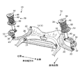
- FIG. 1 shows right and left front suspensions 10 (hereinafter simply referred to as suspensions 10) as vehicle suspension devices according to an exemplary embodiment.
- suspensions 10 right and left front suspensions 10
- the front, rear, left, right, top and bottom of the vehicle body 1 are simply referred to as front, back, left, right, top and bottom, respectively.
- Each suspension 10 is a strut suspension provided between a vehicle wheel 30 (here, a front wheel and also a steering wheel) and the vehicle body 1, and a hub 32 of the wheel 30 via a bearing 34.
- a knuckle 35 that supports the knuckle 35, a lower arm 20 that connects the knuckle 35 to a subframe (also called a suspension cross member) 12 that forms a part of the vehicle body 1, and a strut 39.
- the subframe 12 extends in the vehicle body width direction and is connected to front side frames (not shown) on the right and left sides of the vehicle body 1, for example.
- the strut 39 is provided between the knuckle 35 and the vehicle body 1 (in the present embodiment, the wheel house 2 (see FIG. 3)).
- the knuckle 35 is provided with a first connected portion 36 connected to the damper 40 at the upper end portion, and the lower end portion of the knuckle 35 is connected to the lower arm 20.
- a connected portion 37 is provided, and a third connected portion 38 connected to the tie rod 6 is provided at the rear end portion of the knuckle 35.
- the first to third connected parts 36 to 38 are disposed on the inner side in the vehicle body width direction than the hub 32.
- a separate knuckle arm may be connected to the knuckle 35 so as to extend rearward. In this case, even if the third connected portion 38 is provided at the tip (rear end) of the knuckle arm. Good.
- the lower arm 20 is provided so as to extend in the front-rear direction at the inner part in the vehicle body width direction and extend while curving from the front end of the part toward the outer side in the vehicle body width direction.
- the lower arm 20 is connected to the subframe 12 via a pair of front and rear connecting portions 21 and 22 at the inner side in the vehicle body width direction.
- the lower arm 20 is supported by the subframe 12 so as to be rotatable about a shaft extending in the front-rear direction at the front connection portion 21, and is rotated about an axis extending in the vertical direction at the rear connection portion 22. It is supported by the subframe 12 as possible.
- the outer end of the lower arm 20 in the vehicle width direction is connected to the second connected portion 37 of the knuckle 35 via the first ball joint 23.
- the knuckle 35 is connected to the subframe 12 (that is, the vehicle body 1) via the lower arm 20.
- the first ball joint 23 corresponds to a connecting portion of the lower arm 20 with respect to the knuckle 35.
- the tie rod 6 is disposed so as to extend in the vehicle body width direction.
- the inner portion of the tie rod 6 in the vehicle width direction is connected to the steering gear box 7 of the steering mechanism. Thereby, the tie rod 6 translates in the vehicle body width direction together with, for example, the rack shaft of the steering gear box 7 in accordance with the steering operation.
- the outer end of the tie rod 6 in the vehicle width direction is connected to the third connected portion 38 of the knuckle 35 via the second ball joint 24.
- the knuckle 35 is connected to the steering mechanism (the steering gear box 7) via the tie rod 6.
- the second ball joint 24 corresponds to a connecting portion of the tie rod 6 with respect to the knuckle 35.
- the second ball joint 24 is arranged behind the first ball joint 23. Further, in the steering neutral state, the second ball joint 24 is arranged offset from the first ball joint 23 inward in the vehicle body width direction.
- the third coupled portion 38 of the knuckle 35 is moved in the vehicle body width direction in response to this, whereby the wheel 30 supported by the knuckle 35 is moved. Steered.
- the strut 39 mainly includes a coil spring 60 that is interposed between the wheel 30 and the vehicle body 1 (wheel house 2) and absorbs an impact acting on the wheel 30, and a vibration of the coil spring 60. It is comprised with the damper 40 to absorb.
- the damper 40 is provided to be extendable and contractable between the wheel 30 and the vehicle body 1 (wheel house 2).
- the damper 40 is a telescopic damper having a cylinder 41 and a piston rod 42. By sliding the piston rod 42 with respect to the cylinder 41, the damper 40 is configured to expand and contract in the direction of the axis C1 of the damper 40.
- the shaft center C1 of the damper 40 is disposed to be inclined with respect to the vertical direction. Specifically, the axis C1 of the damper 40 is inclined inward in the vehicle body width direction toward the upper side (see FIG. 3) and inclined rearward toward the upper side (see FIG. 4).
- the lower end portion of the cylinder 41 is connected and fixed to the first connected portion 36 of the knuckle 35.
- a lower spring seat 50 is attached to the vicinity of the upper end of the cylinder 41.
- the lower spring seat 50 is fixed to the outer peripheral surface of the cylinder 41 by welding, for example.
- a seat rubber 54 (see FIG. 5) is provided on the upper surface of the lower spring seat 50.
- the piston rod 42 is provided so as to protrude upward from the cylinder 41.
- An upper mount 44 is attached to the upper end portion of the piston rod 42.
- the upper mount 44 is fixed to the wheel house 2 of the vehicle body 1 by, for example, bolts. As a result, the upper end portion of the damper 40 is connected to the vehicle body 1 via the upper mount 44.
- An upper spring seat 46 is provided below the upper mount 44.
- the upper spring seat 46 is attached to the upper end portion of the piston rod 42 via the upper mount 44. Thereby, the space
- a seat rubber 48 is provided on the lower surface of the upper spring seat 46.
- a bellows-like dust cover 43 that covers the piston rod 42 is provided.
- the coil spring 60 is interposed between the upper spring seat 46 and the lower spring seat 50.
- the seat rubbers 48 and 54 are interposed between the coil spring 60 and the upper spring seat 46 and between the coil spring 60 and the lower spring seat 50, respectively, thereby reducing and extending the impact. The noise is reduced.
- the upper spring seat 46 and the lower spring seat 50 correspond to a pair of upper and lower spring support portions.
- the coil spring 60 is provided so as to surround the piston rod 42 and the dust cover 43 of the damper 40.
- the coil spring 60 is wound clockwise from the upper end side toward the lower end side. This winding direction is the same in the right and left struts 39. In the right and left struts 39, the coil spring 60 may be wound counterclockwise from the upper end side toward the lower end side.
- the coil spring 60 is arranged such that the center P2 of the lower end portion is offset from the center P1 of the upper end portion outside the vehicle body width direction and to the rear side in the front-rear direction. Further, the center P2 of the lower end portion of the coil spring 60 is arranged at an up-down position where the center P2 is located and is offset from the axial center C1 of the damper 40 in the vehicle body width direction and to the rear side in the front-rear direction. ing.
- the offset amounts in the vehicle body width direction and the front-rear direction of the center P2 of the lower end with respect to the center P1 of the upper end of the coil spring 60 are equal between the right and left struts 39. Further, at the vertical position where the center P2 of the lower end portion of the coil spring 60 is located, the offset amount in the vehicle width direction and the front-rear direction of the center P2 with respect to the axis C1 of the damper 40 is also equal between the right and left struts 39. .
- the coil spring 60 is disposed so as to be inclined inwardly in the vehicle body width direction toward the upper side as a whole. Further, as shown in FIG. 4, the coil spring 60 is disposed so as to be inclined toward the front side toward the upper side as a whole.
- the load axis C2 of the coil spring 60 is arranged along the direction inclined outward in the vehicle body width direction and rearward in the front-rear direction toward the lower side.
- the load axis C ⁇ b> 2 of the coil spring 60 is inclined outward in the vehicle body width direction downward, like the axis C ⁇ b> 1 of the damper 40.
- the inclination angle of the coil spring 60 with respect to the vertical direction of the load axis C2 is larger than the inclination angle of the axial center C1 of the damper 40 with respect to the vertical direction.
- the load axis C ⁇ b> 2 of the coil spring 60 is inclined downward toward the rear side, unlike the axis C ⁇ b> 1 of the damper 40, with respect to the inclination in the front-rear direction relative to the vertical direction. .
- the elastic force of the coil spring 60 arranged in the above-described posture acts on the lower spring seat 50 in a direction inclined outward in the vehicle body width direction toward the lower side and rearward in the front-rear direction.
- the upper spring seat 46 can act in a direction inclined upward inward of the vehicle body width direction and forward in the front-rear direction.
- a load F2 (see FIG. 8) along the direction inclined inward in the vehicle body width direction and in the front-rear direction toward the upper side is applied to the upper end portion of the damper 40 from the coil spring 60 to the upper spring seat 46. And can be input via the upper mount 44.
- the straight line L1 extends in the vehicle width direction toward the rear side. It will be arrange
- the moment M1 (which causes the knuckle 35 and the damper 40 to rotate around the virtual axis along the straight line L1).
- a moment M1 is generated to rotate the knuckle 35 and the damper 40 in the clockwise direction when viewed from the front side.
- the load F ⁇ b> 1 is input to the upper end portion of the damper 40 from the wheel house 2 of the vehicle body 1 through the upper mount 44.
- the load F1 input from the vehicle body 1 to the upper end portion of the damper 40 acts in a direction inclined rearward toward the outer side in the vehicle body width direction.
- the load F2 (upward load indicated by arrows in both the upward and downward directions in FIG. 8) input from the coil spring 60 to the upper end portion of the damper 40 is directed inward in the vehicle body width direction. Acting in a direction inclined forward. Thereby, the load F1 from the vehicle body 1 is effectively offset by the load F2 from the coil spring 60.
- the damper 40 can be smoothly operated to improve the riding comfort and driving stability of the vehicle. Can be made.
- the upper surface of the lower spring seat 50 has a concavo-convex shape capable of positioning the seat rubber 54 at a predetermined position. Therefore, the seat rubber 54 is reliably positioned by being placed on the lower spring seat 50.
- the coil spring 60 is positioned by placing a lower end portion of the coil spring 60 on a sheet rubber 54 formed in a groove shape.
- the seat rubber 54 is formed in a substantially arc shape in plan view, and a stopper portion 55 is provided at one end portion in the circumferential direction of the seat rubber 54.
- the coil spring 60 is positioned with high accuracy by being set on the seat rubber 54 so that the lower end of the coil spring 60 comes into contact with the stopper portion 55. Thereby, the load axis C2 of the coil spring 60 is accurately arranged along the above-described inclination direction, and as a result, it is possible to suppress the bending moment from acting on the damper 40.
- the same parts are used between the right and left struts 39 as the respective constituent parts 40, 44, 46, 48, 50, 54, 60 of the strut 39, as in the conventional case.
- the circumferential phase of the entire strut including the coil spring is usually shifted by 180 ° between the right and left struts.
- the phase relationship of the coil spring 60 between the right and left struts 39 is different from the conventional one.
- FIG. 6 showing the first comparative example
- FIG. 7 showing the second comparative example
- FIG. 8 showing the configuration of the present embodiment.
- the load axis of the coil spring 160 is arranged in parallel to the vehicle body width direction as seen from the vertical direction, as in the conventional general strut suspension.
- the circumferential phase of the entire right strut 139A and the left strut 139 including the coil spring 160 and the lower spring seat 150 for positioning the coil spring 160 is 180 ° between the right and left struts 139A, 139B. It's off.
- the right and left struts 139A and 139B are arranged point-symmetrically in a plan view, thereby realizing the arrangement of the load shaft as described above.
- the offset amount D10 of the tip 161 on the lower end side of the coil spring 160 with respect to the axis C10 of the damper 140 is equal between the right and left struts 139A, 139B.
- the elastic force F10 of the coil spring 160 acting on the upper end portion of the damper 140 does not include a front-rear direction component, and therefore, as shown in FIG.
- the load F1 acting in the direction inclined in the direction from the vehicle body 1 to the upper end of the damper 140 cannot be offset by the elastic force F10 of the coil spring 160, a bending moment is applied to the damper 140. Cannot be effectively suppressed.
- the right and left struts 139A and 139B of the first comparative example are shifted in phase by the same angle in the clockwise direction when viewed from above.
- the right and left struts 139A and 139B are 180 ° out of phase, and in the front-rear direction, the offset amount D20 of the tip 161 on the lower end side of the coil spring 160 relative to the axis C10 of the damper 140 is determined.
- the direction of the load axis of the coil spring 160 is inclined in the front-rear direction with respect to the vehicle body width direction.
- the elastic force F20 of the coil spring 160 can be applied in the direction inclined rearward toward the upper side, and the load F1 from the vehicle body 1 is canceled by the elastic force F20. It becomes possible to do.
- the elastic force F30 of the coil spring 160 acts in a direction inclined rearward toward the upper side, so that the load F1 from the vehicle body 1 is canceled by the elastic force F30. Therefore, the bending moment acting on the damper 140 cannot be effectively suppressed.
- the right side is referred to as the right side strut 39A
- the left side is referred to as the left side strut 39B.
- the load axis C2 (see FIGS. 3 and 4) of the coil spring 60 is disposed so as to incline forward toward the upper side in both the right and left struts 39A and 39B. Therefore, in both the right and left struts 39A and 39B, the load F1 from the vehicle body 1 can be canceled by the elastic force of the coil spring 60 (the load F2), and thus a bending moment acts on the damper 40. Can be effectively suppressed.
- the load axis C2 of the coil spring 60 in the right strut 39A and the load axis C2 of the coil spring 60 in the left strut 39B are bilaterally symmetric (vehicle body) It is arranged symmetrically with respect to the center line in the width direction. Therefore, in both the right and left struts 39 ⁇ / b> A and 39 ⁇ / b> B, the elastic force of the coil spring 60 is similarly applied to the upper end portion of the damper 40, so that the bending moment suppressing effect of the damper 40 can be exhibited similarly. it can.
- the circumferential phase shift of the entire right strut 39A and the entire left strut 39 differs from the conventional 180 °. ing. That is, the right and left struts 39A and 39B are asymmetrically arranged in plan view.
- the arrangement having such a phase relationship may be performed for at least the coil spring 60, the lower spring seat 50, and the seat rubber 54 in the right and left struts 39A and 39B, and the other components are the first comparative example. Similarly, it may be arranged so as to be point-symmetric.
- the offset amounts D1, D2 of the tip 61 on the lower end side of the coil spring 60 with respect to the axial center C1 of the damper 40 in the front-rear direction at the vertical position where the tip 61 on the lower end side of the coil spring 60 is disposed are:
- the same coil spring 60 can be used in the right and left struts 39A and 39B. Therefore, it is possible to reduce the cost of parts compared to the case where different coil springs are used for the right and left struts 39A and 39B.
- the same coil spring 60 means a coil spring having the same winding direction, shape, size, spring characteristics and the like.
- the example has been described in which the axis C1 of the damper 40 is disposed so as to incline toward the upper side in the vehicle body width direction and the rear side in the front-rear direction.
- the present invention can also be applied to the case where it is arranged in a direction different from the above-described embodiment with respect to the vertical direction, or when it is arranged along the vertical direction.
- the present invention is useful for a strut type vehicle suspension device including a damper and a coil spring.
Landscapes
- Engineering & Computer Science (AREA)
- Mechanical Engineering (AREA)
- Chemical & Material Sciences (AREA)
- Combustion & Propulsion (AREA)
- Transportation (AREA)
- Vehicle Body Suspensions (AREA)
Abstract
車両用懸架装置(フロントサスペンション(10))において、ナックル(35)に対するロアアーム(20)及びタイロッド(6)の両連結部(23,24)のうち車体前側に配置された一方の連結部(23)に比べて、車体後側に配置された他方の連結部(24)が、操舵中立状態において、車体幅方向内側にオフセットして配置され、コイルスプリング(60)の下端部の中心(P2)が、コイルスプリング(60)の上端部の中心(P1)よりも車体幅方向の外側でかつ車体前後方向の後側にオフセットして配置されている。
Description
本発明は、車体と車輪との間に設けられる車両用懸架装置に関する。
車両用のストラット式懸架装置では、ダンパとコイルスプリングとによって、車両の車体を支持するストラット(支柱)が構成されるため、車両の走行中に路面から車輪のハブに荷重が入力されるとき、該荷重がナックル等を軽油してダンパに伝達されることで、ダンパに曲げモーメントが作用する場合がある。この場合、ダンパの摺動部における摩擦力が増大することで、ダンパのスムーズな作動が阻害されて、車両の乗り心地や操縦安定性に悪影響を及ぼすことがある。
そのため、例えば特許文献1に開示されているように、ストラット式懸架装置において、ダンパの軸心に対してコイルスプリングの荷重軸を車体下側に向かって車体幅方向外側へ傾斜させることで、上記のようにダンパに作用する曲げモーメントを、コイルスプリングの弾性力によって相殺させる技術が知られている。
ところで、図9に示すように、ストラット式のフロントサスペンションにおいて、ダンパ140の下端部を支持するナックル135には、サブフレーム(サスペンションメンバ)112等を介して車体に連結されたロアアーム120、及び、ステアリングギヤボックスに連結されたタイロッド106の各車体幅方向外側端部が、それぞれ連結部123,124(ボールジョイント等で構成)を介して連結される。これらの連結部123,124は、通常、車体幅方向において、車輪130のハブ132よりも内側に配置され、車体前後方向において、相互に間隔をあけて配置される。
この種のフロントサスペンションにおいて、前後一対の連結部123,124は、車輪130のハブ132よりも車体幅方向内側に配置されるため、車両の走行中に路面から車輪130のハブ132に荷重が入力されると、一対の連結部123,124を結ぶ仮想の直線L100に沿った仮想の軸を中心にして、ナックル135及びダンパ140を回動させるようなモーメントM100(図9では、車体前側から見て時計回り方向にナックル135及びダンパ140を回動させるようなモーメントM100)が生じる。
図9に示す例のように、車体前側の連結部123に比べて車体後側の連結部124が車体幅方向内側に位置する場合、一対の連結部123,124を結ぶ直線L100は、車体後側に向かって車体幅方向内側に傾斜した方向に沿って配置されるため、モーメントM100が生じたとき、ダンパ140の上端部には、車体側から、車体幅方向外側に向かって車体後側に傾斜した方向の荷重F100が入力される。
すなわち、このとき、ダンパ140の上端部に入力される荷重F100は、車体幅方向の外側に向かう方向の成分Fxだけでなく、車体前後方向の後側へ向かう方向の成分Fyも含むことになる。
前述の従来の構成では、コイルスプリング160の荷重軸をダンパ140の軸心に対して車体幅方向に傾斜させることで、ダンパ140の上端部に入力される荷重F100における車体幅方向の成分Fxによりダンパ140に作用する曲げモーメントを、コイルスプリング160の弾性力によって相殺することは可能である。
しかし、前記従来の構成では、車体上下方向に対してコイルスプリング160の荷重軸を車体前後方向に傾斜させることは行われていない。そのため、前記従来の構成では、ダンパ140の上端部に入力される荷重F100における車体前後方向の成分Fyによりダンパ140に作用する曲げモーメントを、コイルスプリング160の弾性力によって相殺することはできない。したがって、ダンパの曲げモーメントの抑制に関して改善の余地がある。
本発明は、斯かる点に鑑みてなされたものであり、その目的とするところは、車両用懸架装置のダンパに曲げモーメントが作用するのをより効果的に抑制してダンパの作動の円滑化を図ることが可能な車両用懸架装置を提供しようとすることにある。
前記の目的を達成するために、本発明では、以下の第1及び第2の車両用懸架装置が提供される。
第1の車両用懸架装置は、車両の車輪を支持するナックルと、前記ナックルを前記車両の車体に連結させるロアアームと、前記ナックルをステアリング機構に連結させるタイロッドと、上端部において前記車体に連結されて下端部において前記ナックルに連結され、軸心方向に伸縮可能に構成されたダンパと、前記ダンパの伸縮に応じて前記ダンパの軸心方向における相互の間隔が変化するように前記ダンパに取り付けられた上下一対のスプリング支持部と、前記上下一対のスプリング支持部間に介装されたコイルスプリングと、を備え、前記ナックルに対する前記ロアアーム及び前記タイロッドの両連結部のうち車体前側に配置された一方の連結部に比べて、車体後側に配置された他方の連結部が、操舵中立状態において、車体幅方向内側にオフセットして配置されており、前記コイルスプリングの下端部の中心が、前記コイルスプリングの上端部の中心よりも車体幅方向の外側でかつ車体前後方向の後側にオフセットして配置されているものである。
前記コイルスプリングの下端部の中心とは、コイルスプリングの最下端の1周分における車体幅方向の中央でかつ車体前後方向の中央の位置を意味し、前記コイルスプリングの上端部の中心とは、コイルスプリングの最上端の1周分における車体幅方向の中央でかつ車体前後方向の中央の位置を意味するものとする。
前記構成により、コイルスプリングの下端部の中心が、該コイルスプリングの上端部の中心よりも車体幅方向の外側でかつ車体前後方向の後側にオフセットして配置されているため、コイルスプリングの弾性力を、下側のスプリング支持部に対しては、車体下側に向かって車体幅方向の外側でかつ車体前後方向の後側に傾斜した方向に作用させることができ、上側のスプリング支持部に対しては、車体上側に向かって車体幅方向の内側でかつ車体前後方向の前側に傾斜した方向に作用させることができる。
路面から車輪に荷重が入力されることで、ナックルに対するロアアーム及びタイロッドの両連結部を結ぶ仮想の直線に沿った仮想の軸を中心にして、ナックル及びダンパを回動させるようなモーメントが発生したとき、車体からダンパの上端部に対して、車体幅方向外側に向かって車体後側に傾斜した方向に荷重が入力される。この荷重は、前述したコイルスプリングの弾性力が上側のスプリング支持部を介してダンパの上端部に作用することで、効果的に相殺される。
したがって、ダンパに曲げモーメントが作用するのを効果的に抑制することができて、ダンパをスムーズに作動させることができる。よって、車両の乗り心地及び操縦安定性を向上させることができる。
前記第1の車両用懸架装置の一実施形態では、前記コイルスプリングの下端部の中心は、該中心が位置する車体上下方向位置において、前記ダンパの軸心よりも車体幅方向の外側でかつ車体前後方向の後側にオフセットして配置されている。
このように、コイルスプリングの下端部の中心が、該中心が位置する車体上下方向位置において、ダンパの軸心よりも車体幅方向の外側でかつ車体前後方向の後側にオフセットして配置されることで、ダンパの軸心が車体上側に向かって車体後側に傾斜して配置される場合であっても、ダンパの周囲を取り巻くように設けられたコイルスプリングを、車体上側に向かって車体前側に傾斜させて配置し易くなる。これにより、コイルスプリングの弾性力を、ダンパの上端部に対して、車体上側に向かって車体幅方向の内側でかつ車体前後方向の前側に傾斜した方向に作用させ易くなる。
前記第1の車両用懸架装置の別の実施形態では、前記ダンパと前記コイルスプリングとで構成されたストラットは、車体右側及び車体左側の車輪のそれぞれに設けられ、前記コイルスプリングの上端部の中心に対する下端部の中心の車体幅方向及び車体前後方向のオフセット量は、車体右側及び車体左側のストラット間で等しい。
このことで、コイルスプリングの上端部の中心に対する下端部の中心の車体幅方向及び車体前後方向のオフセット量が、車体右側及び車体左側のストラット間で等しいため、車体右側及び車体左側のストラットのいずれにおいても、コイルスプリングの弾性力をダンパの上端部に対して同様に作用させて、ダンパの曲げモーメント抑制効果を同様に発揮させることができる。
前記別の実施形態において、前記コイルスプリングの下端側の先端が配置された車体上下方向位置において、車体前後方向における前記ダンパの軸心に対する前記コイルスプリングの下端側の先端のオフセット量が、車体右側及び車体左側のストラット間で異なっていてもよい。
このことにより、コイルスプリングの下端側の先端が配置された車体上下方向位置において、車体前後方向におけるダンパの軸心に対するコイルスプリングの下端側の先端のオフセット量を、車体右側及び車体左側のストラット間で異ならせるという、車体右側及び車体左側のストラットの非対称的な配置を採用しつつ、車体右側及び車体左側のストラットにおいて、ダンパの曲げモーメント抑制効果を同様に発揮させることができる。
また、前記別の実施形態において、車体右側のストラットにおける前記コイルスプリングと、車体左側の前記ストラットにおけるコイルスプリングとは、それぞれの上端側から下端側に向かって同一方向に巻かれていてもよい。
これにより、車体右側及び車体左側のストラットにおいて、同じ方向に巻かれたコイルスプリングを用いて、ダンパの曲げモーメント抑制効果を同様に発揮させることができる。
第2の車両用懸架装置は、車両の車輪を支持するナックルと、前記ナックルを前記車両の車体に連結させるロアアームと、前記ナックルをステアリング機構に連結させるタイロッドと、上端部において前記車体に連結されて下端部において前記ナックルに連結され、軸心方向に伸縮可能に構成されたダンパと、前記ダンパの伸縮に応じて前記ダンパの軸心方向における相互の間隔が変化するように前記ダンパに取り付けられた上下一対のスプリング支持部と、前記上下一対のスプリング支持部間に介装されたコイルスプリングと、を備え、前記ナックルに対する前記ロアアーム及び前記タイロッドの両連結部のうち車体前側に配置された一方の連結部に比べて、車体後側に配置された他方の連結部が、操舵中立状態において、車体幅方向内側にオフセットして配置されており、前記コイルスプリングの荷重軸が、車体下側に向かって車体幅方向の外側でかつ車体前後方向の後側に傾斜した方向に沿って配置されているものである。
前記コイルスプリングの荷重軸とは、上下一対のスプリング支持部間においてコイルスプリングを経由して伝達される荷重の方向を示す仮想の軸を意味するものとする。
この構成により、コイルスプリングの荷重軸が、車体下側に向かって車体幅方向の外側でかつ車体前後方向の後側に傾斜した方向に沿って配置されていることで、車体上側に向かって車体幅方向の内側でかつ車体前後方向の前側に傾斜した方向に沿ったコイルスプリングの弾性力を、上側のスプリング支持部を介してダンパの上端部に作用させることができる。
そのため、前記モーメントが発生して車体からダンパの上端部に対して、車体幅方向外側に向かって車体後側に傾斜した方向に荷重が入力されたときに、該荷重を、コイルスプリングの弾性力によって効果的に相殺することができる。
したがって、ダンパに曲げモーメントが作用するのを効果的に抑制することができて、ダンパをスムーズに作動させることができる。よって、車両の乗り心地及び操縦安定性を向上させることができる。
前記第2の車両用懸架装置の一実施形態では、前記ダンパと前記コイルスプリングとで構成されたストラットは、車体右側及び車体左側の車輪のそれぞれに設けられ、車体右側のストラットにおける前記コイルスプリングの荷重軸と、車体左側のストラットにおける前記コイルスプリングの荷重軸とは、車体前後方向及び車体上下方向のいずれから見ても、左右対称に配置されている。
このことで、車体右側のストラットにおけるコイルスプリングの荷重軸と、車体左側のストラットにおけるコイルスプリングの荷重軸とが、車体前後方向及び車体上下方向のいずれから見ても、左右対称に配置されていることにより、車体右側及び車体左側のストラットのいずれにおいても、コイルスプリングの弾性力をダンパの上端部に対して同様に作用させて、ダンパの曲げモーメント抑制効果を同様に発揮させることができる。
前記第2の車両用懸架装置の前記一実施形態において、前記コイルスプリングの下端側の先端が配置された車体上下方向位置において、車体前後方向における前記ダンパの軸心に対する前記コイルスプリングの下端側の先端のオフセット量が、車体右側及び車体左側のストラット間で異なっていてもよい。
このことにより、コイルスプリングの下端側の先端が配置された車体上下方向位置において、車体前後方向におけるダンパの軸心に対するコイルスプリングの下端側の先端のオフセット量を、車体右側及び車体左側のストラット間で異ならせるという、車体右側及び車体左側のストラットの非対称的な配置を採用しつつ、車体右側及び車体左側のストラットにおいて、ダンパの曲げモーメント抑制効果を同様に発揮させることができる。
また、前記第2の車両用懸架装置の前記一実施形態において、車体右側のストラットにおける前記コイルスプリングと、車体左側のストラットにおける前記コイルスプリングとは、それぞれの上端側から下端側に向かって同一方向に巻かれていてもよい。
これにより、車体右側及び車体左側のストラットにおいて、同じ方向に巻かれたコイルスプリングを用いて、ダンパの曲げモーメント抑制効果を同様に発揮させることができる。
以上説明したように、本発明の車両用懸架装置によると、ダンパに曲げモーメントが作用するのを効果的に抑制することができて、ダンパをスムーズに作動させることができ、よって、車両の乗り心地及び操縦安定性を向上させることができる。
以下、例示的な実施形態を図面に基づいて詳細に説明する。
図1は、例示的な実施形態に係る車両用懸架装置としての右側及び左側のフロントサスペンション10(以下、単にサスペンション10という)を示す。以下の説明において、車両の車体1(図1~図3参照)についての前、後、左、右、上及び下を、それぞれ単に前、後、左、右、上及び下という。
各サスペンション10は、車両の車輪30(ここでは、前輪であり、操舵輪でもある)と車体1との間に設けられたストラット式のサスペンションであって、軸受34を介して車輪30のハブ32を回転可能に支持するナックル35と、該ナックル35を、車体1の一部を構成するサブフレーム(サスペンションクロスメンバとも呼ばれる)12に連結させるロアアーム20と、ストラット39とを備えている。
サブフレーム12は、車体幅方向に延びていて、車体1の例えば右側及び左側のフロントサイドフレーム(図示せず)に連結されている。ストラット39は、ナックル35と車体1(本実施形態では、ホイールハウス2(図3参照))との間に設けられている。
図2~図4に示すように、ナックル35の上端部には、ダンパ40に連結される第1被連結部36が設けられ、ナックル35の下端部には、ロアアーム20に連結される第2被連結部37が設けられ、ナックル35の後端部には、タイロッド6に連結される第3被連結部38が設けられている。第1~第3被連結部36~38は、ハブ32よりも車体幅方向内側に配置されている。
尚、ナックル35に別体のナックルアームが後側に延びるように連結されていてもよく、この場合、該ナックルアームの先端部(後端部)に第3被連結部38が設けられてもよい。
図1及び図2に示すように、ロアアーム20は、その車体幅方向内側部分においては前後方向に延びかつ該部分の前端から車体幅方向外側に向かって湾曲しながら延びるように設けられている。
ロアアーム20は、その車体幅方向内側部分において、前後一対の連結部21,22を介してサブフレーム12に連結されている。ロアアーム20は、前側の連結部21においては、前後方向に延びる軸周りに回動可能なようにサブフレーム12に支持され、後側の連結部22においては、上下方向に延びる軸周りに回動可能なようにサブフレーム12に支持されている。
図3及び図4に示すように、ロアアーム20の車体幅方向外側端部は、第1ボールジョイント23を介してナックル35の第2被連結部37に連結されている。これにより、ナックル35は、ロアアーム20を介してサブフレーム12(つまり車体1)に連結されることになる。第1ボールジョイント23は、ナックル35に対するロアアーム20の連結部に相当する。
図2及び図3に示すように、タイロッド6は、車体幅方向に延びるように配設されている。タイロッド6の車体幅方向内側部分は、ステアリング機構のステアリングギヤボックス7に連結されている。これにより、タイロッド6は、ステアリング操作に応じて、ステアリングギヤボックス7の例えばラック軸と共に、車体幅方向に並進移動する。
タイロッド6の車体幅方向外側端部は、第2ボールジョイント24を介してナックル35の第3被連結部38に連結されている。これにより、ナックル35は、タイロッド6を介してステアリング機構(ステアリングギヤボックス7)に連結されることになる。第2ボールジョイント24は、ナックル35に対するタイロッド6の連結部に相当する。
第2ボールジョイント24は、第1ボールジョイント23よりも後側に配置されている。また、操舵中立状態において、第2ボールジョイント24は、第1ボールジョイント23よりも車体幅方向内側にオフセットして配置されている。
ステアリング操作に応じてタイロッド6が車体幅方向に並進移動すると、これに応じて、ナックル35の第3被連結部38が車体幅方向に動かされ、これにより、ナックル35に支持された車輪30が操舵される。
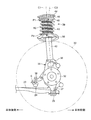
図3に示すように、ストラット39は、主として、車輪30と車体1(ホイールハウス2)との間に介在されて車輪30に作用する衝撃を吸収するコイルスプリング60と、コイルスプリング60の振動を吸収するダンパ40とで構成されている。ダンパ40は、車輪30と車体1(ホイールハウス2)との間で伸縮可能に設けられている。
ダンパ40は、シリンダ41とピストンロッド42とを有する伸縮式ダンパである。シリンダ41に対してピストンロッド42が摺動することで、ダンパ40が、該ダンパ40の軸心C1の方向に伸縮するように構成されている。
ダンパ40の軸心C1は、上下方向に対して傾斜して配置されている。具体的に、ダンパ40の軸心C1は、上側に向かって車体幅方向内側に傾斜しているとともに(図3参照)、上側に向かって後側に傾斜している(図4参照)。
シリンダ41の下端部は、ナックル35の第1被連結部36に連結固定されている。シリンダ41の上端近傍部には、ロアスプリングシート50が取り付けられている。ロアスプリングシート50は、例えば溶接によって、シリンダ41の外周面に固定されている。ロアスプリングシート50の上面には、シートラバー54(図5参照)が設けられている。
ピストンロッド42は、シリンダ41から上側に突出するように設けられている。ピストンロッド42の上端部には、アッパマウント44が取り付けられている。アッパマウント44は、例えばボルトによって、車体1のホイールハウス2に固定されている。これにより、ダンパ40の上端部は、アッパマウント44を介して車体1に連結されることになる。
アッパマウント44の下側には、アッパスプリングシート46が設けられている。アッパスプリングシート46は、アッパマウント44を介してピストンロッド42の上端部に取り付けられている。これにより、ダンパ40の軸心方向におけるアッパスプリングシート46とロアスプリングシート50との間隔が、ダンパ40の伸縮に応じて変化するようになっている。アッパスプリングシート46の下面には、シートラバー48が設けられている。
シリンダ41の上端とアッパスプリングシート46との間には、ピストンロッド42を覆う、例えば蛇腹状のダストカバー43が設けられている。
コイルスプリング60は、アッパスプリングシート46とロアスプリングシート50との間に介装されている。コイルスプリング60とアッパスプリングシート46との間、及び、コイルスプリング60とロアスプリングシート50との間には、それぞれ前記シートラバー48,54が介在されており、これにより、衝撃の緩和、延いては異音の低減が図られている。アッパスプリングシート46及びロアスプリングシート50は、上下一対のスプリング支持部に相当する。
コイルスプリング60は、ダンパ40のピストンロッド42及びダストカバー43の周囲を取り巻くように設けられている。図示の例において、コイルスプリング60は、その上端側から下端側に向かって時計回り方向に巻かれている。この巻き方向は、右側及び左側のストラット39において同一である。尚、右側及び左側のストラット39において、コイルスプリング60は、その上端側から下端側に向かって反時計回り方向に巻かれていてもよい。
図3及び図4に示すように、コイルスプリング60は、その下端部の中心P2が上端部の中心P1よりも車体幅方向の外側でかつ前後方向の後側にオフセットして配置されている。また、コイルスプリング60の下端部の中心P2は、該中心P2が位置する上下方向位置において、ダンパ40の軸心C1よりも車体幅方向の外側でかつ前後方向の後側にオフセットして配置されている。
コイルスプリング60の上端部の中心P1に対する下端部の中心P2の車体幅方向及び前後方向のオフセット量は、右側及び左側のストラット39間で等しい。また、コイルスプリング60の下端部の中心P2が位置する上下方向位置において、ダンパ40の軸心C1に対する該中心P2の車体幅方向及び前後方向のオフセット量も、右側及び左側のストラット39間で等しい。
図3に示すように、コイルスプリング60は、全体として、上側に向かって車体幅方向内側に傾斜して配置されている。また、図4に示すように、コイルスプリング60は、全体として、上側に向かって前側に傾斜して配置されている。
図3及び図4に示すように、コイルスプリング60の荷重軸C2は、下側に向かって車体幅方向の外側でかつ前後方向の後側に傾斜した方向に沿って配置されている。図3に示すように、上下方向に対する車体幅方向への傾斜に関して、コイルスプリング60の荷重軸C2は、ダンパ40の軸心C1と同じく、下側に向かって車体幅方向外側に傾斜しているが、コイルスプリング60の荷重軸C2の上下方向に対する傾斜角度は、ダンパ40の軸心C1の上下方向に対する傾斜角度よりも大きい。一方、図4に示すように、上下方向に対する前後方向への傾斜に関して、コイルスプリング60の荷重軸C2は、ダンパ40の軸心C1とは異なり、下側に向かって後側に傾斜している。
以上のような姿勢で配置されたコイルスプリング60の弾性力は、ロアスプリングシート50に対しては、下側に向かって車体幅方向の外側でかつ前後方向の後側に傾斜した方向に作用し、アッパスプリングシート46に対しては、上側に向かって車体幅方向の内側でかつ前後方向の前側に傾斜した方向に作用し得る。
これにより、ダンパ40の上端部には、上側に向かって車体幅方向の内側でかつ前後方向の前側に傾斜した方向に沿った荷重F2(図8参照)が、コイルスプリング60からアッパスプリングシート46及びアッパマウント44を介して入力され得る。
ところで、図2に示すように、前述の第1ボールジョイント23の中心と第2ボールジョイント24の中心とを仮想の直線L1で結んだ場合、この直線L1は、後側に向かって車体幅方向の内側に傾斜した方向に沿って配置されることになる。
そのため、車両の走行中に路面から車輪30のハブ32に荷重が入力されると、直線L1に沿った仮想の軸を中心にして、ナックル35及びダンパ40を回動させようとするモーメントM1(図2に示す右側のストラット39では、前側から見て時計回り方向にナックル35及びダンパ40を回動させようとするモーメントM1)が発生する。このとき、ダンパ40の上端部には、車体1のホイールハウス2からアッパマウント44を介して荷重F1が入力されることになる。
このようにして車体1からダンパ40の上端部に入力される荷重F1は、車体幅方向外側に向かって後側に傾斜した方向に作用する。これに対して、コイルスプリング60からダンパ40の上端部に入力される荷重F2(図8の上向き及び下向きの両方に矢印を記載しているうちの上向きの荷重)は、車体幅方向内側に向かって前側に傾斜した方向に作用する。これにより、車体1からの荷重F1が、コイルスプリング60からの荷重F2によって効果的に相殺される。
したがって、本実施形態によれば、ダンパ40に曲げモーメントが作用するのを効果的に抑制することができ、これにより、ダンパ40をスムーズに作動させて、車両の乗り心地及び操縦安定性を向上させることができる。
図5に示すように、ロアスプリングシート50の上面は、シートラバー54を所定位置に位置決め可能な凹凸形状を有している。そのため、シートラバー54は、ロアスプリングシート50上に載置されることで、確実に位置決めされる。そして、コイルスプリング60は、その下端部が、溝状に形成されたシートラバー54に載置されることで、位置決めされる。
シートラバー54は、平面視で概略円弧状に形成されており、シートラバー54の周方向の一端部には、ストッパ部55が設けられている。コイルスプリング60は、その下端側の先端がストッパ部55に当接するように、シートラバー54上にセットされることで、精度良く位置決めされる。これにより、コイルスプリング60の荷重軸C2は、前述の傾斜方向に沿って精度良く配置され、この結果、ダンパ40に曲げモーメントが作用するのを抑制することができる。
ところで、本実施形態では、従来と同様に、ストラット39の各構成部品40,44,46,48,50,54,60として、右側及び左側のストラット39間で同一の部品が用いられている。従来は、通常、コイルスプリングを含むストラット全体の周方向の位相を、右側及び左側のストラット間で180°ずらして配置する。本実施形態では、右側及び左側のストラット39間でのコイルスプリング60の位相関係が、従来とは異なる。
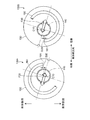
以下、第1比較例を示す図6、第2比較例を示す図7、及び、本実施形態の構成を示す図8を参照しながら、コイルスプリング60の位相に関する構成について説明する。
図6に示す第1比較例は、従来の一般的なストラット式サスペンションと同様、コイルスプリング160の荷重軸が、上下方向から見て車体幅方向に平行に配置されたものである。
第1比較例では、コイルスプリング160及びこれを位置決めするロアスプリングシート150を含む右側のストラット139A全体及び左側のストラット139全体の周方向の位相が、右側及び左側のストラット139A,139B間で180°ずれている。このように、平面視で、右側及び左側のストラット139A,139Bが点対称に配置されることで、前記のような荷重軸の配置が実現される。
この場合、前後方向において、ダンパ140の軸心C10に対するコイルスプリング160の下端側の先端161のオフセット量D10は、右側及び左側のストラット139A,139B間で等しくなる。
しかしながら、第1比較例では、ダンパ140の上端部に作用するコイルスプリング160の弾性力F10が、前後方向の成分を含まないため、図2に示すような、車体幅方向外側に向かって後側に傾斜した方向に作用する荷重F1が車体1からダンパ140の上端部に作用したときに、この荷重F1をコイルスプリング160の弾性力F10によって相殺することはできず、よって、ダンパ140に曲げモーメントが作用するのを効果的に抑制することはできない。
図7に示す第2比較例は、第1比較例の右側及び左側のストラット139A,139B全体を、上側から見て、時計回り方向に同じ角度だけ位相をずらしたものである。第2比較例においても、右側及び左側のストラット139A,139B間で位相が180°ずれているともに、前後方向において、ダンパ140の軸心C10に対するコイルスプリング160の下端側の先端161のオフセット量D20は、右側及び左側のストラット139A,139B間で等しくなっている。
第2比較例では、コイルスプリング160の荷重軸の方向が、車体幅方向に対して前後方向に傾斜される。そして、右側のストラット139Aにおいては、コイルスプリング160の弾性力F20を、上側に向かって後側に傾斜した方向に作用させることができ、この弾性力F20により、車体1からの前記荷重F1を相殺することが可能になる。
しかしながら、左側のストラット139Bにおいては、コイルスプリング160の弾性力F30が、上側に向かって後側に傾斜した方向に作用することになるため、車体1からの前記荷重F1を弾性力F30によって相殺することができず、よって、ダンパ140に曲げモーメントが作用するのを効果的に抑制することはできない。
次に、図8に示す本実施形態の構成について説明する。ここでの説明では、ストラット39について、右側のものを、右側のストラット39Aといい、左側のものを、左側のストラット39Bという。
本実施形態では、コイルスプリング60の荷重軸C2(図3及び図4参照)が、右側及び左側のストラット39A,39Bのいずれにおいても、上側に向かって前側に傾斜して配置されている。そのため、右側及び左側のストラット39A,39Bのいずれにおいても、車体1からの前記荷重F1をコイルスプリング60の弾性力(前記荷重F2)によって相殺することができ、よって、ダンパ40に曲げモーメントが作用するのを効果的に抑制することができる。
本実施形態では、右側のストラット39Aにおけるコイルスプリング60の荷重軸C2と、左側のストラット39Bにおけるコイルスプリング60の荷重軸C2とは、前後方向及び上下方向のいずれから見ても、左右対称(車体幅方向中央ラインに対して左右対称)に配置されている。そのため、右側及び左側のストラット39A,39Bのいずれにおいても、コイルスプリング60の弾性力をダンパ40の上端部に対して同様に作用させて、ダンパ40の曲げモーメント抑制効果を同様に発揮させることができる。
このようなコイルスプリング60の荷重軸C2の配置を実現するために、本実施形態では、右側のストラット39A全体及び左側のストラット39全体の周方向の位相のずれが、従来の180°とは異なっている。つまり、平面視で、右側及び左側のストラット39A,39Bが非対称的に配置されている。
尚、このような位相関係となる配置は、右側及び左側のストラット39A,39Bにおいて、少なくともコイルスプリング60、ロアスプリングシート50及びシートラバー54について行えばよく、その他の構成部品は、第1比較例と同様に、点対称となるように配置されていてもよい。
本実施形態では、コイルスプリング60の下端側の先端61が配置された上下方向位置において、前後方向におけるダンパ40の軸心C1に対するコイルスプリング60の下端側の先端61のオフセット量D1,D2が、右側及び左側のストラット39A,39B間で異なっている。このように右側及び左側のストラット39A,39Bのコイルスプリング60を非対称的に配置することによって、右側及び左側のストラット39A,39Bの両方において、前述の、ダンパ40の曲げモーメント抑制効果が実現可能となる。
また、このような構成の実現に際して、右側及び左側のストラット39A,39Bで、同じコイルスプリング60を用いることができる。したがって、仮に右側及び左側のストラット39A,39Bで異なるコイルスプリングを用いる場合に比べて、部品コストの低減を図ることができる。前記同じコイルスプリング60とは、巻き方向、形状、大きさ、ばね特性等が同じコイルスプリングを意味する。
本発明は、前記実施形態に限られるものではなく、請求の範囲の主旨を逸脱しない範囲で代用が可能である。
例えば、前記実施形態では、ダンパ40の軸心C1が上側に向かって車体幅方向の内側でかつ前後方向の後側に傾斜して配置される例を説明したが、ダンパ40の軸心C1が上下方向に対して前記実施形態とは異なる方向に傾斜して配置される場合、又は、上下方向に沿って配置される場合にも、本発明を適用することができる。
前述の実施形態は単なる例示に過ぎず、本発明の範囲を限定的に解釈してはならない。本発明の範囲は請求の範囲によって定義され、請求の範囲の均等範囲に属する変形や変更は、全て本発明の範囲内のものである。
本発明は、ダンパとコイルスプリングとを備えたストラット式の車両用懸架装置に有用である。
1 車体
6 タイロッド
7 ステアリング機構のステアリングギヤボックス
10 フロントサスペンション(車両用懸架装置)
20 ロアアーム
23 第1ボールジョイント(ナックルに対するロアアームの連結部)
24 第2ボールジョイント(ナックルに対するタイロッドの連結部)
30 車輪(前輪、操舵輪)
35 ナックル
39 ストラット
40 ダンパ
46 アッパスプリングシート(上側のスプリング支持部)
50 ロアスプリングシート(下側のスプリング支持部)
60 コイルスプリング
61 コイルスプリングの下端側の先端
C1 ダンパの軸心
C2 コイルスプリングの荷重軸
P1 コイルスプリングの上端部の中心
P2 コイルスプリングの下部の中心
Claims (9)
- 車両用懸架装置であって、
車両の車輪を支持するナックルと、
前記ナックルを前記車両の車体に連結させるロアアームと、
前記ナックルをステアリング機構に連結させるタイロッドと、
上端部において前記車体に連結されて下端部において前記ナックルに連結され、軸心方向に伸縮可能に構成されたダンパと、
前記ダンパの伸縮に応じて前記ダンパの軸心方向における相互の間隔が変化するように前記ダンパに取り付けられた上下一対のスプリング支持部と、
前記上下一対のスプリング支持部間に介装されたコイルスプリングと、を備え、
前記ナックルに対する前記ロアアーム及び前記タイロッドの両連結部のうち車体前側に配置された一方の連結部に比べて、車体後側に配置された他方の連結部が、操舵中立状態において、車体幅方向内側にオフセットして配置されており、
前記コイルスプリングの下端部の中心が、前記コイルスプリングの上端部の中心よりも車体幅方向の外側でかつ車体前後方向の後側にオフセットして配置されていることを特徴とする車両用懸架装置。 - 請求項1記載の車両用懸架装置において、
前記コイルスプリングの下端部の中心は、該中心が位置する車体上下方向位置において、前記ダンパの軸心よりも車体幅方向の外側でかつ車体前後方向の後側にオフセットして配置されていることを特徴とする車両用懸架装置。 - 請求項1又は2記載の車両用懸架装置において、
前記ダンパと前記コイルスプリングとで構成されたストラットは、車体右側及び車体左側の車輪のそれぞれに設けられ、
前記コイルスプリングの上端部の中心に対する下端部の中心の車体幅方向及び車体前後方向のオフセット量は、車体右側及び車体左側のストラット間で等しいことを特徴とする車両用懸架装置。 - 請求項3記載の車両用懸架装置において、
前記コイルスプリングの下端側の先端が配置された車体上下方向位置において、車体前後方向における前記ダンパの軸心に対する前記コイルスプリングの下端側の先端のオフセット量が、車体右側及び車体左側のストラット間で異なっていることを特徴とする車両用懸架装置。 - 請求項3又は4記載の車両用懸架装置において、
車体右側のストラットにおける前記コイルスプリングと、車体左側の前記ストラットにおけるコイルスプリングとは、それぞれの上端側から下端側に向かって同一方向に巻かれていることを特徴とする車両用懸架装置。 - 車両用懸架装置であって、
車両の車輪を支持するナックルと、
前記ナックルを前記車両の車体に連結させるロアアームと、
前記ナックルをステアリング機構に連結させるタイロッドと、
上端部において前記車体に連結されて下端部において前記ナックルに連結され、軸心方向に伸縮可能に構成されたダンパと、
前記ダンパの伸縮に応じて前記ダンパの軸心方向における相互の間隔が変化するように前記ダンパに取り付けられた上下一対のスプリング支持部と、
前記上下一対のスプリング支持部間に介装されたコイルスプリングと、を備え、
前記ナックルに対する前記ロアアーム及び前記タイロッドの両連結部のうち車体前側に配置された一方の連結部に比べて、車体後側に配置された他方の連結部が、操舵中立状態において、車体幅方向内側にオフセットして配置されており、
前記コイルスプリングの荷重軸が、車体下側に向かって車体幅方向の外側でかつ車体前後方向の後側に傾斜した方向に沿って配置されていることを特徴とする車両用懸架装置。 - 請求項6記載の車両用懸架装置において、
前記ダンパと前記コイルスプリングとで構成されたストラットは、車体右側及び車体左側の車輪のそれぞれに設けられ、
車体右側のストラットにおける前記コイルスプリングの荷重軸と、車体左側のストラットにおける前記コイルスプリングの荷重軸とは、車体前後方向及び車体上下方向のいずれから見ても、左右対称に配置されていることを特徴とする車両用懸架装置。 - 請求項7記載の車両用懸架装置において、
前記コイルスプリングの下端側の先端が配置された車体上下方向位置において、車体前後方向における前記ダンパの軸心に対する前記コイルスプリングの下端側の先端のオフセット量が、車体右側及び車体左側のストラット間で異なっていることを特徴とする車両用懸架装置。 - 請求項7又は8記載の車両用懸架装置において、
車体右側のストラットにおける前記コイルスプリングと、車体左側のストラットにおける前記コイルスプリングとは、それぞれの上端側から下端側に向かって同一方向に巻かれていることを特徴とする車両用懸架装置。
Priority Applications (3)
| Application Number | Priority Date | Filing Date | Title |
|---|---|---|---|
| US16/462,923 US10981426B2 (en) | 2016-11-21 | 2017-11-01 | Suspension device for vehicles |
| EP17872081.9A EP3530499B1 (en) | 2016-11-21 | 2017-11-01 | Suspension device for vehicles |
| CN201780071678.0A CN109963731B (zh) | 2016-11-21 | 2017-11-01 | 车辆用悬架装置 |
Applications Claiming Priority (2)
| Application Number | Priority Date | Filing Date | Title |
|---|---|---|---|
| JP2016-225791 | 2016-11-21 | ||
| JP2016225791A JP6332417B2 (ja) | 2016-11-21 | 2016-11-21 | 車両用懸架装置 |
Publications (1)
| Publication Number | Publication Date |
|---|---|
| WO2018092588A1 true WO2018092588A1 (ja) | 2018-05-24 |
Family
ID=62145366
Family Applications (1)
| Application Number | Title | Priority Date | Filing Date |
|---|---|---|---|
| PCT/JP2017/039527 Ceased WO2018092588A1 (ja) | 2016-11-21 | 2017-11-01 | 車両用懸架装置 |
Country Status (5)
| Country | Link |
|---|---|
| US (1) | US10981426B2 (ja) |
| EP (1) | EP3530499B1 (ja) |
| JP (1) | JP6332417B2 (ja) |
| CN (1) | CN109963731B (ja) |
| WO (1) | WO2018092588A1 (ja) |
Families Citing this family (2)
| Publication number | Priority date | Publication date | Assignee | Title |
|---|---|---|---|---|
| JP3326711B2 (ja) | 1995-08-02 | 2002-09-24 | 株式会社タイガーカワシマ | 穀類自動計量機における自動シャッタ制御装置 |
| DE102018220235A1 (de) * | 2018-11-26 | 2020-05-28 | Ford Global Technologies, Llc | Einzelradaufhängung für ein Kraftfahrzeug |
Citations (8)
| Publication number | Priority date | Publication date | Assignee | Title |
|---|---|---|---|---|
| JPS4634275Y1 (ja) * | 1967-10-28 | 1971-11-26 | ||
| JPH09300932A (ja) * | 1996-05-20 | 1997-11-25 | Toyota Motor Corp | サスペンション装置 |
| JPH1148729A (ja) * | 1997-07-31 | 1999-02-23 | Nissan Motor Co Ltd | サスペンション装置 |
| JPH1148728A (ja) * | 1997-07-31 | 1999-02-23 | Nissan Motor Co Ltd | 操舵輪用サスペンション装置 |
| JP2002178736A (ja) * | 2000-12-14 | 2002-06-26 | Chuo Spring Co Ltd | 自動車用懸架コイルばね及び該懸架コイルばねを備えたストラット型懸架装置 |
| JP2003326932A (ja) | 2002-05-09 | 2003-11-19 | Nok Corp | ストラット型サスペンション装置 |
| JP2010089549A (ja) * | 2008-10-03 | 2010-04-22 | Honda Motor Co Ltd | スタビライザ取付構造 |
| JP2015174514A (ja) * | 2014-03-14 | 2015-10-05 | 富士重工業株式会社 | 車体構造 |
Family Cites Families (8)
| Publication number | Priority date | Publication date | Assignee | Title |
|---|---|---|---|---|
| GB1237938A (ja) * | 1967-10-28 | 1971-07-07 | ||
| JP2714969B2 (ja) * | 1989-01-13 | 1998-02-16 | マツダ株式会社 | 自動車のサスペンション装置 |
| JPH03112708A (ja) * | 1989-09-27 | 1991-05-14 | Mazda Motor Corp | 自動車のサスペンション装置 |
| FR2804376A1 (fr) * | 2000-02-01 | 2001-08-03 | Michelin Ets | Methode de compensation du tirage d'un vehicule equipe de suspension mac pherson et jambe de force permettant cette compensation |
| JP4254599B2 (ja) * | 2004-04-01 | 2009-04-15 | トヨタ自動車株式会社 | ストラット式サスペンション |
| US7513514B1 (en) | 2004-10-29 | 2009-04-07 | Niwot Corporation | Adjustable ball joint connection assembly |
| JP5151770B2 (ja) * | 2007-11-26 | 2013-02-27 | 日産自動車株式会社 | ロアスプリングシートの取り付け構造及びロアスプリングシート |
| KR101448761B1 (ko) * | 2013-08-20 | 2014-10-08 | 현대자동차 주식회사 | 캐스터 능동 제어 장치 |
-
2016
- 2016-11-21 JP JP2016225791A patent/JP6332417B2/ja active Active
-
2017
- 2017-11-01 CN CN201780071678.0A patent/CN109963731B/zh active Active
- 2017-11-01 WO PCT/JP2017/039527 patent/WO2018092588A1/ja not_active Ceased
- 2017-11-01 US US16/462,923 patent/US10981426B2/en active Active
- 2017-11-01 EP EP17872081.9A patent/EP3530499B1/en active Active
Patent Citations (8)
| Publication number | Priority date | Publication date | Assignee | Title |
|---|---|---|---|---|
| JPS4634275Y1 (ja) * | 1967-10-28 | 1971-11-26 | ||
| JPH09300932A (ja) * | 1996-05-20 | 1997-11-25 | Toyota Motor Corp | サスペンション装置 |
| JPH1148729A (ja) * | 1997-07-31 | 1999-02-23 | Nissan Motor Co Ltd | サスペンション装置 |
| JPH1148728A (ja) * | 1997-07-31 | 1999-02-23 | Nissan Motor Co Ltd | 操舵輪用サスペンション装置 |
| JP2002178736A (ja) * | 2000-12-14 | 2002-06-26 | Chuo Spring Co Ltd | 自動車用懸架コイルばね及び該懸架コイルばねを備えたストラット型懸架装置 |
| JP2003326932A (ja) | 2002-05-09 | 2003-11-19 | Nok Corp | ストラット型サスペンション装置 |
| JP2010089549A (ja) * | 2008-10-03 | 2010-04-22 | Honda Motor Co Ltd | スタビライザ取付構造 |
| JP2015174514A (ja) * | 2014-03-14 | 2015-10-05 | 富士重工業株式会社 | 車体構造 |
Also Published As
| Publication number | Publication date |
|---|---|
| EP3530499B1 (en) | 2021-04-14 |
| JP2018083439A (ja) | 2018-05-31 |
| CN109963731A (zh) | 2019-07-02 |
| EP3530499A1 (en) | 2019-08-28 |
| US10981426B2 (en) | 2021-04-20 |
| US20190322149A1 (en) | 2019-10-24 |
| JP6332417B2 (ja) | 2018-05-30 |
| EP3530499A4 (en) | 2020-04-15 |
| CN109963731B (zh) | 2022-06-17 |
Similar Documents
| Publication | Publication Date | Title |
|---|---|---|
| JP4460831B2 (ja) | 車両ホイールのサスペンションシステム | |
| JP5514808B2 (ja) | サスペンション装置 | |
| JP5536967B1 (ja) | 車両 | |
| CN107571698B (zh) | 汽车的前悬架构造 | |
| JP2008018924A (ja) | サスペンション装置 | |
| WO2018092587A1 (ja) | 車両用懸架装置 | |
| WO2018092588A1 (ja) | 車両用懸架装置 | |
| JP6365008B2 (ja) | 車両用懸架装置 | |
| JP6358314B2 (ja) | 車両前部構造 | |
| GB2582330A (en) | Steering axle assembly | |
| KR102240958B1 (ko) | 주행안정성과 부드러운 승차감을 위한 차량 로어암 제어 장치 | |
| JP6426997B2 (ja) | 鉄道車両用の操舵台車 | |
| JP4370518B2 (ja) | 自動車のフロントサスペンション装置 | |
| JP2001270313A (ja) | トレーリングアーム式リアサスペンション | |
| JP5454509B2 (ja) | リヤサスペンション装置 | |
| JP2011173562A (ja) | 車両用サスペンション装置 | |
| JP4664796B2 (ja) | 操舵輪用サスペンション装置 | |
| JP6497343B2 (ja) | 車両のサスペンション構造 | |
| CN107031738A (zh) | 轮胎盖板装置 | |
| JP6420681B2 (ja) | ストラット式サスペンション装置 | |
| JP6510807B2 (ja) | 鉄道車両用の操舵台車 | |
| JP2007118672A (ja) | 前輪用サスペンション装置 | |
| JP4534136B2 (ja) | 自動車のフロントサスペンション装置 | |
| JP4109602B2 (ja) | トーションビーム式サスペンション | |
| JP4701947B2 (ja) | 操舵輪用ストラット式サスペンション |
Legal Events
| Date | Code | Title | Description |
|---|---|---|---|
| 121 | Ep: the epo has been informed by wipo that ep was designated in this application |
Ref document number: 17872081 Country of ref document: EP Kind code of ref document: A1 |
|
| NENP | Non-entry into the national phase |
Ref country code: DE |
|
| ENP | Entry into the national phase |
Ref document number: 2017872081 Country of ref document: EP Effective date: 20190524 |