WO2018092829A1 - Éléments de glissement - Google Patents
Éléments de glissement Download PDFInfo
- Publication number
- WO2018092829A1 WO2018092829A1 PCT/JP2017/041212 JP2017041212W WO2018092829A1 WO 2018092829 A1 WO2018092829 A1 WO 2018092829A1 JP 2017041212 W JP2017041212 W JP 2017041212W WO 2018092829 A1 WO2018092829 A1 WO 2018092829A1
- Authority
- WO
- WIPO (PCT)
- Prior art keywords
- dimple
- sliding
- dimples
- peripheral edges
- fluid
- Prior art date
- Legal status (The legal status is an assumption and is not a legal conclusion. Google has not performed a legal analysis and makes no representation as to the accuracy of the status listed.)
- Ceased
Links
Images







Classifications
-
- F—MECHANICAL ENGINEERING; LIGHTING; HEATING; WEAPONS; BLASTING
- F16—ENGINEERING ELEMENTS AND UNITS; GENERAL MEASURES FOR PRODUCING AND MAINTAINING EFFECTIVE FUNCTIONING OF MACHINES OR INSTALLATIONS; THERMAL INSULATION IN GENERAL
- F16C—SHAFTS; FLEXIBLE SHAFTS; ELEMENTS OR CRANKSHAFT MECHANISMS; ROTARY BODIES OTHER THAN GEARING ELEMENTS; BEARINGS
- F16C17/00—Sliding-contact bearings for exclusively rotary movement
- F16C17/12—Sliding-contact bearings for exclusively rotary movement characterised by features not related to the direction of the load
-
- F—MECHANICAL ENGINEERING; LIGHTING; HEATING; WEAPONS; BLASTING
- F16—ENGINEERING ELEMENTS AND UNITS; GENERAL MEASURES FOR PRODUCING AND MAINTAINING EFFECTIVE FUNCTIONING OF MACHINES OR INSTALLATIONS; THERMAL INSULATION IN GENERAL
- F16C—SHAFTS; FLEXIBLE SHAFTS; ELEMENTS OR CRANKSHAFT MECHANISMS; ROTARY BODIES OTHER THAN GEARING ELEMENTS; BEARINGS
- F16C17/00—Sliding-contact bearings for exclusively rotary movement
- F16C17/04—Sliding-contact bearings for exclusively rotary movement for axial load only
- F16C17/045—Sliding-contact bearings for exclusively rotary movement for axial load only with grooves in the bearing surface to generate hydrodynamic pressure, e.g. spiral groove thrust bearings
-
- F—MECHANICAL ENGINEERING; LIGHTING; HEATING; WEAPONS; BLASTING
- F16—ENGINEERING ELEMENTS AND UNITS; GENERAL MEASURES FOR PRODUCING AND MAINTAINING EFFECTIVE FUNCTIONING OF MACHINES OR INSTALLATIONS; THERMAL INSULATION IN GENERAL
- F16C—SHAFTS; FLEXIBLE SHAFTS; ELEMENTS OR CRANKSHAFT MECHANISMS; ROTARY BODIES OTHER THAN GEARING ELEMENTS; BEARINGS
- F16C33/00—Parts of bearings; Special methods for making bearings or parts thereof
- F16C33/02—Parts of sliding-contact bearings
- F16C33/04—Brasses; Bushes; Linings
- F16C33/06—Sliding surface mainly made of metal
- F16C33/10—Construction relative to lubrication
- F16C33/1025—Construction relative to lubrication with liquid, e.g. oil, as lubricant
- F16C33/103—Construction relative to lubrication with liquid, e.g. oil, as lubricant retained in or near the bearing
-
- F—MECHANICAL ENGINEERING; LIGHTING; HEATING; WEAPONS; BLASTING
- F16—ENGINEERING ELEMENTS AND UNITS; GENERAL MEASURES FOR PRODUCING AND MAINTAINING EFFECTIVE FUNCTIONING OF MACHINES OR INSTALLATIONS; THERMAL INSULATION IN GENERAL
- F16C—SHAFTS; FLEXIBLE SHAFTS; ELEMENTS OR CRANKSHAFT MECHANISMS; ROTARY BODIES OTHER THAN GEARING ELEMENTS; BEARINGS
- F16C33/00—Parts of bearings; Special methods for making bearings or parts thereof
- F16C33/02—Parts of sliding-contact bearings
- F16C33/04—Brasses; Bushes; Linings
- F16C33/06—Sliding surface mainly made of metal
- F16C33/10—Construction relative to lubrication
- F16C33/1025—Construction relative to lubrication with liquid, e.g. oil, as lubricant
- F16C33/106—Details of distribution or circulation inside the bearings, e.g. details of the bearing surfaces to affect flow or pressure of the liquid
- F16C33/1075—Wedges, e.g. ramps or lobes, for generating pressure
-
- F—MECHANICAL ENGINEERING; LIGHTING; HEATING; WEAPONS; BLASTING
- F16—ENGINEERING ELEMENTS AND UNITS; GENERAL MEASURES FOR PRODUCING AND MAINTAINING EFFECTIVE FUNCTIONING OF MACHINES OR INSTALLATIONS; THERMAL INSULATION IN GENERAL
- F16C—SHAFTS; FLEXIBLE SHAFTS; ELEMENTS OR CRANKSHAFT MECHANISMS; ROTARY BODIES OTHER THAN GEARING ELEMENTS; BEARINGS
- F16C33/00—Parts of bearings; Special methods for making bearings or parts thereof
- F16C33/72—Sealings
- F16C33/74—Sealings of sliding-contact bearings
- F16C33/741—Sealings of sliding-contact bearings by means of a fluid
-
- F—MECHANICAL ENGINEERING; LIGHTING; HEATING; WEAPONS; BLASTING
- F16—ENGINEERING ELEMENTS AND UNITS; GENERAL MEASURES FOR PRODUCING AND MAINTAINING EFFECTIVE FUNCTIONING OF MACHINES OR INSTALLATIONS; THERMAL INSULATION IN GENERAL
- F16J—PISTONS; CYLINDERS; SEALINGS
- F16J15/00—Sealings
- F16J15/16—Sealings between relatively-moving surfaces
- F16J15/34—Sealings between relatively-moving surfaces with slip-ring pressed against a more or less radial face on one member
-
- F—MECHANICAL ENGINEERING; LIGHTING; HEATING; WEAPONS; BLASTING
- F16—ENGINEERING ELEMENTS AND UNITS; GENERAL MEASURES FOR PRODUCING AND MAINTAINING EFFECTIVE FUNCTIONING OF MACHINES OR INSTALLATIONS; THERMAL INSULATION IN GENERAL
- F16J—PISTONS; CYLINDERS; SEALINGS
- F16J15/00—Sealings
- F16J15/16—Sealings between relatively-moving surfaces
- F16J15/34—Sealings between relatively-moving surfaces with slip-ring pressed against a more or less radial face on one member
- F16J15/3404—Sealings between relatively-moving surfaces with slip-ring pressed against a more or less radial face on one member and characterised by parts or details relating to lubrication, cooling or venting of the seal
- F16J15/3408—Sealings between relatively-moving surfaces with slip-ring pressed against a more or less radial face on one member and characterised by parts or details relating to lubrication, cooling or venting of the seal at least one ring having an uneven slipping surface
- F16J15/3412—Sealings between relatively-moving surfaces with slip-ring pressed against a more or less radial face on one member and characterised by parts or details relating to lubrication, cooling or venting of the seal at least one ring having an uneven slipping surface with cavities
-
- F—MECHANICAL ENGINEERING; LIGHTING; HEATING; WEAPONS; BLASTING
- F16—ENGINEERING ELEMENTS AND UNITS; GENERAL MEASURES FOR PRODUCING AND MAINTAINING EFFECTIVE FUNCTIONING OF MACHINES OR INSTALLATIONS; THERMAL INSULATION IN GENERAL
- F16C—SHAFTS; FLEXIBLE SHAFTS; ELEMENTS OR CRANKSHAFT MECHANISMS; ROTARY BODIES OTHER THAN GEARING ELEMENTS; BEARINGS
- F16C2223/00—Surface treatments; Hardening; Coating
-
- F—MECHANICAL ENGINEERING; LIGHTING; HEATING; WEAPONS; BLASTING
- F16—ENGINEERING ELEMENTS AND UNITS; GENERAL MEASURES FOR PRODUCING AND MAINTAINING EFFECTIVE FUNCTIONING OF MACHINES OR INSTALLATIONS; THERMAL INSULATION IN GENERAL
- F16C—SHAFTS; FLEXIBLE SHAFTS; ELEMENTS OR CRANKSHAFT MECHANISMS; ROTARY BODIES OTHER THAN GEARING ELEMENTS; BEARINGS
- F16C2240/00—Specified values or numerical ranges of parameters; Relations between them
- F16C2240/40—Linear dimensions, e.g. length, radius, thickness, gap
- F16C2240/44—Hole or pocket sizes
Definitions
- the present invention relates to a sliding part suitable for a sliding part, for example, a mechanical seal, a bearing, and the like.
- the present invention relates to a sliding component such as a seal ring or a bearing that requires a fluid to be interposed in the sliding surface to reduce friction and prevent fluid from leaking from the sliding surface.
- Example 1 of Patent Document 1 a fluid in which an outer end opens on a radially outer side (high-pressure side Y) of a seal surface and an inner end closes in the seal surface of a rotary seal ring of a mechanical seal.
- a plurality of introduction grooves and a plurality of dynamic pressure generating grooves communicating with the fluid introduction grooves and extending in the counterclockwise direction in the circumferential direction are provided, and the rotary seal ring is rotated in the clockwise direction. It is disclosed that a fluid lubrication state is achieved by allowing fluid to flow into a dynamic pressure generating groove and generating dynamic pressure between the seal surface of the rotating seal ring and the seal surface of the stationary seal ring.
- Patent Document 2 discloses that a fluid lubrication state is achieved by forming a large number of circular dimples or elliptical dimples in a regular arrangement pattern on the sliding surface of the stationary ring of the mechanical seal.
- Japanese Patent Laid-Open No. 5-60247 (second and third pages, FIGS. 2 and 4) Japanese Patent Laid-Open No. 9-133222 (Page 4, FIGS. 1 and 2)
- Example 1 of Patent Document 1 since the dynamic pressure generating groove extends only in one of the circumferential directions with respect to the fluid introduction groove, the rotary sealing ring is in the clockwise direction, that is, the fluid introduction groove on the upstream side. If it is not rotated in the direction in which it is positioned, a positive dynamic pressure cannot be generated by the dynamic pressure generating groove, and a fluid lubrication state cannot be achieved. Further, even if the rotary seal ring is rotated in the direction in which positive dynamic pressure is generated, the pressurized fluid supplied to the sliding surface from the dynamic pressure generating groove extending in the circumferential direction is supplied to the low pressure fluid side of the sliding surface. Since most of the fluid to be leaked leaks, there is a problem of reducing the sealing performance.
- Example 2 of Patent Document 1 by providing dynamic pressure generating grooves on both sides of the fluid introduction groove, positive dynamic pressure can be generated for both forward and reverse rotations. .
- the flow of fluid flowing from the upstream dynamic pressure generating groove into the fluid introduction groove and the flow of fluid flowing from the outer diameter side opening into the fluid introduction groove are generated, upstream dynamic pressure generation occurs.
- the fluid flowing into the fluid introduction groove from the groove collides with the fluid flowing into the fluid introduction groove from the opening on the outer diameter side, and the fluid cannot be efficiently fed into the dynamic pressure generating groove on the downstream side.
- a sufficient fluid lubrication state cannot be achieved as compared with the case where the dynamic pressure generating groove is extended only on one side of the groove.
- the pressurized fluid supplied from the dynamic pressure generating groove to the low-pressure fluid side of the sliding surface almost leaks, there is a problem that the sealing performance is deteriorated.
- Patent Document 2 although the fluid lubrication state can be formed regardless of the rotation direction, the circular and elliptical dimples generate a positive pressure and a negative pressure almost symmetrically in the dimple. As a result, a sufficient positive dynamic pressure cannot be generated, and a sufficient fluid lubrication state cannot be achieved.
- the present invention has been made paying attention to such problems, and can reduce friction by interposing a fluid on the sliding surface regardless of the rotation direction, and can improve the sealing performance regardless of the rotation direction.
- the object is to provide a sliding part.
- the sliding component of the present invention is: A sliding component that slides relative to each other on a sliding surface, wherein at least one sliding surface includes a plurality of polygonal dimples having a peripheral edge formed without breaks, Of the peripheral edges of the dimples formed in a polygonal shape, a pair of peripheral edges extending in the radial direction across the radial axis of the sliding part is open and inclined toward the high-pressure fluid side, and the pair of peripheral edges The length of the peripheral edge connecting the peripheral edge portions on the high-pressure fluid side is not more than the length of the pair of peripheral edges.
- the fluid that has flowed into the dimple from the upstream peripheral edge and damped the downstream peripheral edge is pumped to the high-pressure fluid side along the peripheral edge that opens and slopes toward the high-pressure fluid side, and continuously merges with other pressurized flows to increase the volume. Therefore, the range of the positive pressure fluid can be expanded from the downstream side to the upstream side of the dimple.
- the outlet side of the pressurized fluid can be narrowed by forming the length of the peripheral edge connecting the ends of the high-pressure fluid side of the pair of peripheral edges to be equal to or shorter than the length of the pair of peripheral edges.
- the pressure region can be made sufficiently larger than the negative pressure region, a sufficient positive pressure can be generated as a whole dimple regardless of the rotation direction, and a sufficient fluid lubrication state can be achieved. Further, since the high-pressure fluid supplied from the dimple to the sliding surface flows outward in the radial direction while continuously flowing into the dimple adjacent in the circumferential direction or the dimple adjacent to the outer diameter side, the flow toward the low-pressure fluid side. And the sealing performance can be improved regardless of the rotation direction.
- the sliding component of the present invention is The plurality of dimples have a bottom portion that is recessed from the sliding surface, and the bottom portions have an equal depth. According to this feature, dimples having uniform lubrication performance and sealing performance can be easily formed.
- the sliding component of the present invention is The plurality of dimples have a bottom portion that is recessed from the sliding surface, and the bottom portions have different depths. According to this feature, a plurality of dimples optimized according to the sliding speed and temperature (fluid viscosity) can be arranged, and good lubricating performance and sealing performance can be obtained.
- the sliding component of the present invention is The plurality of dimples have different sizes. According to this feature, a plurality of dimples optimized according to the sliding speed and temperature (fluid viscosity) can be arranged, and good lubricating performance and sealing performance can be obtained.
- the sliding component of the present invention is The bottom portion of the dimple is characterized in that it is inclined downward from the vicinity of the pair of peripheral edges toward the radial axis. According to this feature, a rapid pressure drop on the upstream side of the dimple can be suppressed, and the pressure can be increased efficiently on the downstream side of the dimple.
- the sliding component of the present invention is The bottom portion of the dimple is characterized by an upward slope from the low pressure fluid side to the high pressure fluid side. According to this feature, the flow that flows in from the upstream side of the dimple, becomes negative pressure, is blocked by the peripheral edge on the downstream side, and becomes positive pressure. Since the pressure further increases, the area of the positive pressure fluid further expands from the downstream side to the upstream side of the dimple, and the positive pressure area in the dimple can be made sufficiently larger than the negative pressure area regardless of the rotation direction.
- the sliding component of the present invention is The bottom portion includes a communication groove that communicates the vicinity of the pair of peripheral edges.
- High pressure fluid can be supplied to the upstream negative pressure region from the positive pressure region downstream of the dimple through the communication groove at the bottom of the dimple, so that the negative pressure region in the dimple can be reduced so that the entire dimple has a sufficient positive pressure. Can be generated.
- the sliding component of the present invention is
- the dimple has a symmetric shape with respect to the radial axis. According to this feature, a dimple having good lubricating performance and sealing performance can be obtained regardless of the rotation direction.
- the sliding component of the present invention is The dimple is formed in a triangular shape. According to this feature, since the shape is simple, the dimple can be easily formed.
- the sliding component of the present invention is The plurality of dimples are annularly arranged on the same diameter, and a plurality of the dimple groups arranged annularly are arranged in the radial direction. According to this feature, it is possible to reduce friction and leakage by evenly arranging dimples having good lubricating performance and sealing performance regardless of the rotation direction over the entire sliding surface.
- the sliding component of the present invention is The dimple groups adjacent in the radial direction are arranged so as to be shifted in the circumferential direction. According to this feature, leakage can be further reduced by arranging the dimple groups adjacent in the radial direction while being shifted in the circumferential direction.
- the sliding component of the present invention is The plurality of dimples are characterized by being randomly arranged. According to this feature, good lubrication performance and sealing performance can be exhibited by the dimples arranged at random, corresponding to the sliding speed and temperature.
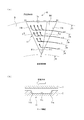
- FIG. 1A is a view taken along the line WW in FIG. 1, showing a sliding surface on which a plurality of dimples are arranged when the outer diameter side of the sliding component is the high-pressure fluid side and the inner diameter side is the low-pressure fluid side;
- B is an enlarged view of a dimple.
- A) is a figure explaining the flow of the fluid in the dimple formed in the sliding component which concerns on Example 1
- (b) is a XX arrow directional view of (a). It is a figure which shows the modification of a dimple.
- (A) is the figure which shows the modification of a dimple
- (a) is when the periphery of the dimple extended in the circumferential direction is comprised in an arc shape, and a pair of periphery extended in the radial direction is comprised with a straight line
- (b) is extended in the circumferential direction when the peripheral edge extending in the circumferential direction is configured by a straight line and the pair of peripheral edges extending in the radial direction is configured by a convex curve toward the inside of the dimple.
- FIG. 6 is a diagram illustrating dimples according to a second embodiment.
- FIG. 8A is a view taken in the direction of arrows YY in FIG. 8, (a) shows a case where the dimple bottom portion is inclined downward from a pair of peripheral edges extending radially toward the center of the dimple, and (b) shows the dimple bottom portion in the radial direction. It is a figure which shows the case where it forms in the downward curved surface toward the center of a dimple from a pair of periphery extended in the direction.
- FIG. 9 is a view taken along the line ZZ in FIG.
- FIG. 10 is a diagram illustrating a dimple according to a third embodiment, where (a) is a diagram illustrating a surface shape of the dimple, and (b) is a diagram illustrating a VV arrow view of (a).
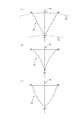
- 4A and 4B are diagrams illustrating a dimple according to a fourth embodiment, where FIG. 5A illustrates a case where the dimple is configured as a quadrangle, FIG. 5B illustrates a case where the dimple is configured as a pentagon, and FIG. 5C illustrates a case where the dimple is configured as a hexagon.
- FIG. 5A illustrates a case where the dimple is configured as a quadrangle
- FIG. 5B illustrates a case where the dimple is configured as a pentagon
- FIG. 5C illustrates a case where the dimple is configured as a hexagon.
- FIG. 5A illustrates a case where the dimple is configured as a quadrangle
- FIG. 5B illustrates a case where the di
- FIG. 1 is a longitudinal sectional view showing an example of a mechanical seal, which is an inside type that seals a sealed fluid on a high-pressure fluid side that is about to leak from the outer periphery of the sliding surface toward the inner peripheral direction.
- a mechanical seal which is an inside type that seals a sealed fluid on a high-pressure fluid side that is about to leak from the outer periphery of the sliding surface toward the inner peripheral direction.
- annular rotating ring 3 provided on the rotating shaft 1 side via a sleeve 2 so as to be rotatable integrally with the rotating shaft 1 and a non-rotating state via a fixed sleeve 6 on the pump housing 4.
- a ring-shaped stationary ring 5 provided in a state that is movable in the axial direction is a sliding surface that is mirror-finished by lapping or the like by a coiled wave spring 8 and a bellows 7 that bias the stationary ring 5 in the axial direction.
- the moving surfaces S are slid closely. That is, this mechanical seal prevents the sealed fluid from flowing out from the outer peripheral side of the rotating shaft 1 to the atmosphere side on the sliding surfaces S of the rotating ring 3 and the stationary ring 5.
- FIG. 2 is a WW arrow view of FIG. 1, and a case where a plurality of dimples 11 are formed on the sliding surface S of the stationary ring 5 will be described as an example.
- the plurality of dimples 11 includes a plurality of dimple groups (four rows in FIG. 1) arranged in the radial direction at equal intervals in the circumferential direction on the same diameter.
- the dimple 11 has a bottom portion 11d (see FIG. 3B) that is recessed from the sliding surface S, and the peripheral edges A1-B1, A1-C1, and B1-C1 of the dimple 11 are surrounded by the sliding surface S without a break. , Formed into a triangle.
- A1 is disposed on the diameter d1 of the stationary ring 5, and the peripheral edge portions B1 and C1 are disposed on d2 having a larger diameter than d1. Further, the pair of peripheral edges A1-B1 and peripheral edges A1-C1 facing each other across the radial axis R are arranged to open toward the high-pressure fluid side so that the distance between the peripheral edges B1-C1 on the high-pressure fluid side becomes wide. .
- the peripheral edges A1-B1 and A1-C1 are arranged so as to form an equal angle ⁇ 1 with respect to the radial axis R, respectively, and the dimples 11 are isosceles symmetrical with respect to the radial axis R. It is a triangle. Furthermore, the length of the peripheral edge B1-C1 connecting the end portions B1 and C1 on the high-pressure fluid side of the pair of peripheral edges A1-B1, A1-C1 is formed to be shorter than the length of the peripheral edges A1-B1, A1-C1. Yes.
- the length of the peripheral edge B1-C1 is desirably set in the range of 50% to 100% of the length of the peripheral edges A1-B1 and A1-C1.
- the length of the peripheral edge B1-C1 connecting the ends B1 and C1 on the high-pressure fluid side of the pair of peripheral edges A1-B1, A1-C1 is shorter than the lengths of the peripheral edges A1-B1, A1-C1. It is preferable. In this case, the length of the peripheral edge B1-C1 is desirably set in the range of 50% to 95% of the length of the peripheral edges A1-B1 and A1-C1.
- FIG. 3A shows the sealed fluid that flows into the dimple 11 when the rotating ring 3 rotates counterclockwise with respect to the stationary ring 5 having a plurality of dimples 11 as represented by flows st1, st2, st3, and st4. I have drawn it schematically.
- 3 (b) is a view taken along the line XX in FIG. 3 (a). When the rotary ring 3 moves relative to the direction indicated by the arrow (counterclockwise direction), the rotary ring 3 and the fixed ring are shown.
- the fluid interposed between the five sliding surfaces tends to follow the moving direction of the rotary ring 3 due to its viscosity, the fluid flows from the right side (upstream side) to the left side (downstream side) of the dimple 11.
- a gap between the rotating ring 3 and the stationary ring 5 is rapidly expanded due to a step caused by the wall portion 11a on the upstream side of the dimple 11, and dynamic pressure (negative pressure) is generated in the region NA1 on the upstream side of the dimple.
- the gap between the rotating ring 3 and the stationary ring 5 is rapidly reduced due to the presence of the wall portion 11b on the downstream side of the dimple 11, and dynamic pressure (positive pressure) is generated in the downstream area of the dimple.
- a pair of peripheral edges A1-B1 and peripheral edges A1-C1 facing each other across the radial axis R have a high pressure so that the distance between the peripheral edges B1-C1 on the high-pressure fluid side is wide. Since it is arranged to open toward the fluid side, the cross-sectional area in the dimple 11 gradually increases toward the outside in the radial direction. Therefore, the fluid that flows into the dimple 11 and becomes negative pressure, and is then dammed up by the wall portion 11b and becomes positive pressure is applied to the wall portion 11b toward the radially outer side where the cross-sectional area in the dimple 11 increases. And is pumped from end A1 to end C1.
- the flow st1 that has flowed into the dimple 11 along the diameter d2 and became high pressure joins the flow st2 that has flowed into the dimple 11 along the diameter d3 and became high pressure, and the high-pressure flow of (st1 + st2). And is pumped from the end A1 toward the end C1 along the wall 11b.
- the flow st3 that has flowed into the dimple 11 along the diameter d4 and becomes high pressure merges with the flow (st1 + st2) to become a high-pressure flow of (st1 + st2 + st3), and radially outward along the wall portion 11b. Pumped.
- the flow st4 which flows into the dimple 11 along the diameter d5 and becomes high pressure, merges with the flow (st1 + st2 + st3) and becomes a high-pressure flow of (st1 + st2 + st3 + st4) along the wall 11b in the radial direction. Pumped outward.
- the fluid that has flowed into the dimple 11 at each radial position of the sliding surface S and has become negative pressure is blocked by the wall portion 11b and increased to positive pressure, and the end portion A1 along the wall portion 11b. Since the volume is increased by continuously joining other high-pressure fluid on the way from the edge C1 to the end C1, the range of the high-pressure fluid is changed from the peripheral edge A1-C1 (downstream side) to the peripheral edge A1-B1 (upstream side). It gradually expands toward.
- the peripheral edge B1-C1 of the dimple 11 serving as the outlet side of the high-pressure fluid is formed shorter than the peripheral edge A1-B1 serving as the inlet side of the fluid, so that the high-pressure fluid can be transferred from the dimple 11 to the rotating ring 3. Since the outlet area that flows into the gap between the fixed ring 5 is narrowed in the circumferential direction, the positive pressure region in the dimple 11 extends from the peripheral edge A1-C1 (downstream side) beyond the radial axis R to the peripheral edge A1-B1. Expand further toward (upstream). Thereby, the positive pressure region in the dimple 11 becomes larger than the negative pressure region, and a sufficient positive pressure can be generated as a whole dimple regardless of the rotation direction.
- the high pressure fluid in the dimple 11 is supplied to the sliding surface S from the outer diameter side end of the peripheral edge A1-C1 and the peripheral edge B1-C1, and the sliding surface S can maintain a fluid lubrication state.
- the high-pressure fluid supplied to the sliding surface S from the outer diameter side end of the peripheral edge A1-C1 continuously flows into the dimples 11 adjacent in the circumferential direction, and from the peripheral edge B1-C1 to the sliding surface S. Since the supplied high-pressure fluid continuously flows into the dimple adjacent to the outer diameter side, the flow toward the low-pressure fluid side can be reduced to reduce leakage.
- the dimple as a whole can generate a positive pressure regardless of the rotation direction and supply a high pressure fluid to the sliding surface S, the sliding surface can be maintained in a fluid lubrication state regardless of the rotation direction.
- the high-pressure fluid supplied to the sliding surface S moves outward in the radial direction while continuously flowing into the dimple 11 adjacent to the circumferential direction or the dimple adjacent to the outer diameter side, so that the flow toward the low-pressure fluid side is reduced.
- the sealing performance can be improved regardless of the rotation direction.
- the peripheral edges A1-B1 and A1-C1 of the dimple 11 are arranged so as to form an equal angle ⁇ 1 with respect to the radial axis R, and the dimple 11 is isosceles symmetrical with respect to the radial axis R. It was a triangle.
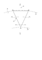
- the peripheral edges A2-C2 and A2-B2 of the dimple 12 may be arranged so as to form different angles ⁇ 1, ⁇ 2 with respect to the radial axis R.
- the size of the negative pressure region NA2 can be reduced by forming the angle ⁇ 1 larger than ⁇ 2, It is possible to generate positive pressure effectively in the counterclockwise direction with high operation frequency.
- the peripheral edges A1-B1, A1-C1 and B1-C1 of the dimple 11 are configured by straight lines, but the present invention is not limited to this.
- the peripheral edges A3-B3 and A3-C3 of the dimple 13 are formed in a straight line, and the peripheral edges B3-C3 are formed in an arc centered on the rotation axis center O.
- a dimple peripheral edge B4-C4 extending in the circumferential direction of the dimple 14 is constituted by a straight line, and a pair of peripheral edges A4-B4, A4-C4 extending in the radial direction are formed inside the dimple.
- FIG. 5 (a) the peripheral edges A3-B3 and A3-C3 of the dimple 13 are formed in a straight line, and the peripheral edges B3-C3 are formed in an arc centered on the rotation axis center O.
- a dimple peripheral edge B4-C4 extending in the circumferential direction of the dimple 14 is constituted by
- the dimple peripheral edge B5-C5 extending in the circumferential direction of the dimple 15 is constituted by a straight line and extends in the radial direction.
- a pair of peripheral edges A5-B5 and A5-C5 may be configured with convex curves facing the outside of the dimple.
- the pressure in the vicinity of the radially outer side C3, C4, C5 on the downstream side of the dimple is the highest in FIG. 5B, and decreases in the order of (a), (c), corresponding to the sliding speed and temperature.
- a positive pressure required at a desired position of the dimple can be generated, and good lubricating performance and sealing performance can be exhibited.
- the peripheral edges A1-B1, A1-C1 and B1-C1 of the dimple 11 are constituted by a single straight line, and the peripheral edges of the dimples 13, 14, 15 are a single straight line or a single straight line.
- the present invention is not limited to this.
- the peripheral edge B6-C6 of the dimple 16 is constituted by an arc centered on the rotation axis center O, and the peripheral edges A6-B6, A6-C6 may be constituted by a plurality of curves. Good.
- the line AB10 connecting the vertices inside the dimples of the plurality of curves forming the peripheral edge A6-B6 and the line AC10 connecting the vertices inside the dimples of the plurality of curves forming the peripheral edge A6-C6 are If they are open to each other with respect to the radial axis R toward the side and the length of the peripheral edge B6-C6 is less than or equal to the length of the entire curved lines of the peripheral edge A6-B6 and the peripheral edge A6-C6,
- the positive pressure region is sufficiently larger than the negative pressure region, and a sufficient positive pressure can be generated as a whole dimple.
- the three peripheral edges A7-B7, A7-C7 and A7-C7 constituting the triangle may be composed of a plurality of curves.
- the line AB11 connecting the vertices inside the dimples of the plurality of curves constituting the peripheral edge A7-B7 and the line AC11 connecting the vertices inside the dimples of the plurality of curves constituting the peripheral edge A6-C6 are: Open to each other with respect to the radial axis R toward the high-pressure fluid side, and the total length of all curves of the peripheral edges B7-C7 is the total length of all curves of the peripheral edges A6-B6, and the total curve length of the peripheral edges A6-C6. If formed below the total length, the positive pressure region in the dimple 16 is sufficiently larger than the negative pressure region, and a sufficient positive pressure can be generated as a whole dimple.
- the plurality of dimples 11 formed on the stationary ring 5 are annularly arranged on the same diameter, and the annularly arranged dimple groups are arranged in a plurality of rows in the radial direction.
- the plurality of dimples 11 formed on the fixed ring 20 are annularly arranged on the same diameter, and the dimple groups adjacent in the radial direction are staggered by shifting in the circumferential direction. It is good also as arrangement. Thereby, since the flow path of the fluid flowing through the sliding surface S can be zigzag, leakage can be reduced.
- the depth and size of the plurality of dimples 11 are formed to be equal, but this is not restrictive.
- the dimples 11 having different depths or sizes or the dimples 11 having different depths and sizes may be randomly arranged so as to be adaptable to different sliding speeds and different temperatures (fluid viscosities).
- the sliding speed and temperature fluid viscosity
- it is optimized for each environment rather than arranging multiple single dimples of the same size and depth. It is possible to obtain better lubricating performance and sealing performance by arranging a plurality of dimples having different sizes and depths.
- the outer peripheral side of the stationary ring 5 is described as the high-pressure fluid side, and the inner diameter side is described as the low-pressure fluid side.
- the inner diameter side is the high-pressure fluid side and all the dimples 31 adjacent in the radial direction are arranged in a line in the radial direction is shown.
- the dimple 31 is arranged such that the peripheral edges facing each other across the radial axis R are opened toward the inner diameter side.
- FIG. 8 shows the surface shape of the dimple 21, which is the same as the surface shape of the dimple 11 of the first embodiment.
- the bottom of the dimple is formed as a wall portion having a certain depth, but in the second embodiment, the bottom of the dimple is different from the first embodiment in that it is inclined. .
- the description of the same configuration as in the above embodiment is omitted.
- FIG. 9 shows a cross section in the circumferential direction of the dimple 21 as viewed in the direction of arrows YY in FIG.
- the bottoms 21e and 21f of the dimple 21 are formed on the downward inclined surfaces from the vicinity of the peripheral edges A8-B8 and A8-C8 facing each other across the radial axis R toward the radial axis R, respectively.
- the bottom is flat.
- the bottom 21g of the dimple 21 is formed on a downward inclined surface toward the radial axis R from the vicinity of the peripheral edges A8-B8 and A8-C8 facing each other across the radial axis R.
- the bottom is formed in a curved surface.
- FIG. 10 shows a radial cross section of the dimple 21 in the ZZ arrow view of FIG.
- the dimple 21 in FIG. 10A has a bottom 21h having a certain depth from the low pressure fluid side to the high pressure fluid side
- the dimple 21 in FIG. 10B has a high pressure fluid from the low pressure fluid side.
- the bottom portion 21j is inclined upward toward the side.
- the range of the positive pressure fluid further expands from the peripheral edge A1-C1 to the peripheral edge A1-B1. Therefore, the positive pressure region can be further expanded as compared with the dimple 21 having a constant depth like the bottom portion 21h, and a sufficient positive pressure can be generated as a whole regardless of the rotation direction. it can.
- bottom portions 21f and 21g of the dimple 21 shown in FIG. 9 and the bottom portions 21h and 21j shown in FIG. 10 may be implemented independently, or the bottom portions of the dimples are inclined in the circumferential direction and the radial direction in combination. May be.
- the bottom of the dimple is formed on a flat surface, but in the third embodiment, the bottom of the dimple is different from the first and second embodiments in that it has a communication groove.
- the same components as those shown in the above-described embodiment are denoted by the same reference numerals and redundant description is omitted.
- a communication groove 41e is formed in the bottom 41d of the dimple 41 so as to face each other with the radial axis R interposed therebetween and to communicate the vicinity of the pair of peripheral edges A9-B9 and A9-C9.
- high-pressure fluid can be supplied from the downstream positive pressure region to the upstream negative pressure region through the communication groove 41e formed in the bottom 41d of the dimple 41, so that the negative pressure region in the dimple 41 is reduced. By reducing, it is possible to generate a sufficient positive pressure for the entire dimple.
- the communication groove 41e of the dimple 41 of the third embodiment can be implemented by combining the dimple of the first embodiment and the dimple of the second embodiment.
- the effect of expanding the positive pressure region in the dimple 41 can be further enhanced without being affected by the rotation direction.
- the depth, width, length, and number of grooves of the communication groove 41e are determined according to the number of rotations, sealing pressure, and type of the sealed fluid, but the amount of foreign matter contained in the sealed fluid is large. In this case, it is desirable to increase the depth and width of the communication groove 41e.
- Example 4 a sliding component according to Example 4 will be described with reference to FIG.
- Example 1 Example 2, and Example 3, the surface shape of the dimple was formed in a triangle, but the dimple in Example 4 was implemented in that it was formed in a polygon having four or more sides. This is different from Example 1, Example 2, and Example 3. Note that the same components as those shown in the embodiment are given the same reference numerals and redundant description is omitted.
- FIG. 12A shows an embodiment in which the surface shape of the dimple 51 is formed in a trapezoidal shape.
- the pair of peripheral edges A10-B10 and D10-C10 extending in the radial direction across the radial axis R are higher in pressure than the peripheral edge A10-D10 on the low-pressure fluid side.
- the peripheral edge B10-C10 on the side is formed wide and inclined toward the high pressure fluid side, and the length of the peripheral edge B10-C10 is less than the length of the peripheral edges A10-B10 and D10-C10. Is done.
- FIG. 12B shows an embodiment in which the surface shape of the dimple 51 is formed in a pentagon.
- a pair of peripheral edges A11-B11-C11 and A11-E11-D11 extending in the radial direction across the radial axis R among the peripheral edges of the dimple formed in a pentagon shape are opened toward the high-pressure fluid side.
- the length of the peripheral edge C11-D11 that is inclined and extends in the circumferential direction on the high-pressure fluid side is less than the length of the peripheral edge A11-B11-C11 and the length of the peripheral edge A11-E11-D11. .
- FIG. 12C shows an embodiment in which the surface shape of the dimple 61 is formed in a hexagon.
- a pair of peripheral edges A12-B12-C12 and F12-E12-D12 extending in the radial direction across the radial axis R among the peripheral edges of the dimples formed in a hexagon are opened toward the high-pressure fluid side.
- the length of the peripheral edge C12-D12 that is inclined and extends in the circumferential direction on the high-pressure fluid side is less than the length of the peripheral edge A12-B12-C12 and the length of the other peripheral edge F12-E12-D12 Is done.
- the positive pressure region in the dimple 41 is expanded without being influenced by the rotation direction, and sufficient positive pressure is generated as a whole dimple. It can be set as the sliding component which can be made to do. Needless to say, a polygonal dimple having six or more peripheral edges can be formed with the same idea as FIGS. 12 (a), (b), and (c). Further, the sliding parts may be formed by combining triangular dimples and quadrangular or more polygonal dimples.
- a plurality of dimples are formed in the same shape, but the present invention is not limited to this.
- dimples having different depths, sizes, and shapes may be randomly arranged so as to be adaptable to different sliding speeds and different temperatures (fluid viscosities).
- each environment has more than a single dimple of the same size, depth and shape. It is possible to obtain better lubrication performance and sealing performance by arranging a plurality of dimples having different sizes, depths, and shapes optimized together.
- the dimple is provided on the sliding surface of the stationary ring, but may be provided on the sliding surface of the rotating ring.
- the sliding component is used for either the pair of rotating rings or the stationary ring in the mechanical seal device.
- the lubricating oil is sealed on one side in the axial direction of the cylindrical sliding surface.
- it can also be used as a sliding part of a bearing that slides with the rotating shaft.
Landscapes
- Engineering & Computer Science (AREA)
- General Engineering & Computer Science (AREA)
- Mechanical Engineering (AREA)
- Chemical & Material Sciences (AREA)
- Oil, Petroleum & Natural Gas (AREA)
- Physics & Mathematics (AREA)
- Fluid Mechanics (AREA)
- Mechanical Sealing (AREA)
- Sliding-Contact Bearings (AREA)
- Sealing Of Bearings (AREA)
Abstract
Le problème décrit par l'invention est de fournir des éléments de glissement permettant de réduire un frottement par une interposition de fluide au niveau de surfaces de glissement indépendamment du sens de rotation, et permettant d'améliorer la performance d'étanchéité indépendamment du sens de rotation. La solution selon l'invention porte sur des éléments de glissement qui glissent l'un par rapport à l'autre au niveau d'une surface de glissement 5, au moins une surface de glissement 5 comportant de multiples dépressions polygonales 11 pourvues de bords périphériques continus. Parmi les bords périphériques des dépressions polygonales 11, deux bords périphériques A1-B1 et A1-C1 qui s'étendent radialement, l'axe radial R de l'élément de glissement étant pris en sandwich entre ces derniers, sont inclinés de façon à s'ouvrir d'un côté fluide haute pression, et la longueur d'un bord périphérique B1-C1 reliant les extrémités B1 et C1 des deux bords périphériques du côté fluide haute pression est inférieure ou égale à la longueur des deux bords périphériques A1-B1 et A1-C1.
Priority Applications (4)
| Application Number | Priority Date | Filing Date | Title |
|---|---|---|---|
| US16/347,996 US10808752B2 (en) | 2016-11-18 | 2017-11-16 | Sliding members |
| CN201780069345.4A CN109964054B (zh) | 2016-11-18 | 2017-11-16 | 滑动部件 |
| EP17870662.8A EP3543552B1 (fr) | 2016-11-18 | 2017-11-16 | Éléments de glissement |
| JP2018551672A JP6890611B2 (ja) | 2016-11-18 | 2017-11-16 | 摺動部材 |
Applications Claiming Priority (2)
| Application Number | Priority Date | Filing Date | Title |
|---|---|---|---|
| JP2016225069 | 2016-11-18 | ||
| JP2016-225069 | 2016-11-18 |
Publications (1)
| Publication Number | Publication Date |
|---|---|
| WO2018092829A1 true WO2018092829A1 (fr) | 2018-05-24 |
Family
ID=62146507
Family Applications (1)
| Application Number | Title | Priority Date | Filing Date |
|---|---|---|---|
| PCT/JP2017/041212 Ceased WO2018092829A1 (fr) | 2016-11-18 | 2017-11-16 | Éléments de glissement |
Country Status (5)
| Country | Link |
|---|---|
| US (1) | US10808752B2 (fr) |
| EP (1) | EP3543552B1 (fr) |
| JP (1) | JP6890611B2 (fr) |
| CN (1) | CN109964054B (fr) |
| WO (1) | WO2018092829A1 (fr) |
Cited By (6)
| Publication number | Priority date | Publication date | Assignee | Title |
|---|---|---|---|---|
| JP2019113144A (ja) * | 2017-12-25 | 2019-07-11 | 大同メタル工業株式会社 | 半割スラスト軸受 |
| US11035411B2 (en) * | 2017-07-14 | 2021-06-15 | Eagle Industry Co., Ltd. | Sliding parts |
| US11053975B2 (en) | 2017-05-19 | 2021-07-06 | Eagle Industry Co., Ltd | Sliding component |
| US11248707B2 (en) | 2017-05-19 | 2022-02-15 | Eagle Industry Co., Ltd | Sliding component |
| CN115280044A (zh) * | 2020-04-07 | 2022-11-01 | 伊格尔工业股份有限公司 | 滑动部件 |
| US11708911B2 (en) | 2017-10-03 | 2023-07-25 | Eagle Industry Co., Ltd. | Sliding component |
Families Citing this family (2)
| Publication number | Priority date | Publication date | Assignee | Title |
|---|---|---|---|---|
| CN119301388A (zh) * | 2022-06-07 | 2025-01-10 | 伊格尔工业股份有限公司 | 滑动部件 |
| CN116771833B (zh) * | 2023-08-11 | 2025-12-19 | 清华大学 | 平头“v”形凹槽织构化表面及摩擦副 |
Citations (5)
| Publication number | Priority date | Publication date | Assignee | Title |
|---|---|---|---|---|
| US3744805A (en) * | 1968-06-08 | 1973-07-10 | Kupfer Asbest Co | Slide ring for axially acting shaft sealing rings |
| JPH0560247A (ja) | 1991-08-26 | 1993-03-09 | Nippon Pillar Packing Co Ltd | 非接触形メカニカルシール |
| JPH09133222A (ja) | 1995-09-08 | 1997-05-20 | Eagle Ind Co Ltd | メカニカルシール用摺動材 |
| US20150226336A1 (en) * | 2012-08-10 | 2015-08-13 | Siemens Aktiengesellschaft | Shaft seal arrangement |
| WO2016143721A1 (fr) * | 2015-03-11 | 2016-09-15 | イーグル工業株式会社 | Élément coulissant |
Family Cites Families (38)
| Publication number | Priority date | Publication date | Assignee | Title |
|---|---|---|---|---|
| DE1775596A1 (de) * | 1968-08-30 | 1972-03-16 | Kupfer Asbest Co | Gleitringe fuer axial wirkende Wellendichtringe |
| US4553857A (en) * | 1983-12-22 | 1985-11-19 | Ney Robert J | Reversible journal bearing uniflow lubrication system |
| US5492341A (en) * | 1990-07-17 | 1996-02-20 | John Crane Inc. | Non-contacting, gap-type seal having a ring with a patterned seal face |
| DE4119324A1 (de) * | 1991-06-12 | 1992-12-17 | Heinz Konrad Prof Dr I Mueller | Gleitringdichtung mit rueckfoerderwirkung und verfahren zu ihrer herstellung |
| US5441283A (en) * | 1993-08-03 | 1995-08-15 | John Crane Inc. | Non-contacting mechanical face seal |
| JP3068432B2 (ja) * | 1995-05-15 | 2000-07-24 | 三菱重工業株式会社 | メカニカルシール |
| MY123377A (en) * | 1999-07-05 | 2006-05-31 | Honda Motor Co Ltd | Sliding members and piston for internal combustion engines |
| US6511226B2 (en) * | 2000-09-05 | 2003-01-28 | Federal-Mogul World Wide, Inc. | Aluminum thrust washer |
| US6739238B2 (en) * | 2000-11-20 | 2004-05-25 | Nissan Motor Co., Ltd. | Sliding structure for a reciprocating internal combustion engine and a reciprocating internal combustion engine using the sliding structure |
| CN2460801Y (zh) * | 2001-01-18 | 2001-11-21 | 王玉明 | 可双向旋转的螺旋槽端面密封装置 |
| US6902168B2 (en) * | 2002-03-19 | 2005-06-07 | Eagle Industry Co., Ltd. | Sliding element |
| JP4205910B2 (ja) * | 2002-04-02 | 2009-01-07 | イーグル工業株式会社 | 摺動部品 |
| JP4316956B2 (ja) * | 2002-10-23 | 2009-08-19 | イーグル工業株式会社 | 摺動部品 |
| CN1272563C (zh) * | 2002-11-07 | 2006-08-30 | 约翰克兰鼎名密封(天津)有限公司 | 双螺旋角三维螺旋槽端面密封装置 |
| JP4719414B2 (ja) * | 2003-12-22 | 2011-07-06 | イーグル工業株式会社 | 摺動部品 |
| US7744094B2 (en) * | 2004-11-09 | 2010-06-29 | Eagle Industry Co., Ltd. | Mechanical seal device |
| FR2912797B1 (fr) * | 2007-02-19 | 2009-08-21 | Turbomeca Sa | Joint d'etancheite magnetique a portance |
| JP5456772B2 (ja) * | 2009-05-25 | 2014-04-02 | イーグル工業株式会社 | シール装置 |
| CN102549281B (zh) * | 2009-09-29 | 2016-08-03 | Ntn株式会社 | 滑动轴承 |
| JP5518527B2 (ja) * | 2010-03-04 | 2014-06-11 | イーグル工業株式会社 | 摺動部品 |
| JP5620794B2 (ja) * | 2010-11-18 | 2014-11-05 | いすゞ自動車株式会社 | ピストンリング |
| WO2012115972A1 (fr) * | 2011-02-22 | 2012-08-30 | The George Washington University | Réduction des frottements pour des composants de moteurs |
| JP5960145B2 (ja) * | 2011-09-10 | 2016-08-02 | イーグル工業株式会社 | 摺動部品及びその製造方法 |
| DE112012004199B4 (de) * | 2011-10-05 | 2024-02-01 | Suzuki Motor Corporation | Gleitendes Bauteil, Verfahren zu seiner Herstellung, und Verfahren zur Herstellung eines Harzfilms |
| JP5772584B2 (ja) * | 2011-12-28 | 2015-09-02 | いすゞ自動車株式会社 | ピストンリング |
| AU2014206300B2 (en) * | 2013-01-16 | 2016-10-13 | Eagle Industry Co., Ltd. | Sliding part |
| EP2948699B1 (fr) * | 2013-01-23 | 2018-08-15 | Flowserve Management Company | Joint d'étanchéité de face mécanique ayant un motif de face trapézoïdal inversé |
| JP2014163402A (ja) * | 2013-02-21 | 2014-09-08 | Daido Metal Co Ltd | 半割スラスト軸受および軸受装置 |
| US9587745B2 (en) * | 2013-04-24 | 2017-03-07 | Eagle Industry Co., Ltd. | Sliding component |
| CN104179718B (zh) * | 2013-05-24 | 2017-05-17 | 高涵文 | 一种结构改进的密封环 |
| EP3048341A4 (fr) * | 2013-09-18 | 2017-04-26 | Eagle Industry Co., Ltd. | Composant coulissant |
| AU2014354094B2 (en) * | 2013-11-22 | 2017-03-16 | Eagle Industry Co., Ltd. | Sliding component |
| EP3163133B1 (fr) * | 2014-06-26 | 2020-02-12 | Eagle Industry Co., Ltd. | Composant glissant |
| CN104265906B (zh) * | 2014-08-06 | 2016-05-18 | 浙江工业大学 | 气体润滑仿鸟翅膀形型槽端面密封结构 |
| CN104235381A (zh) * | 2014-08-29 | 2014-12-24 | 江苏大学 | 一种带有储液槽的动静压结合机械密封结构 |
| JP2016079523A (ja) * | 2014-10-15 | 2016-05-16 | 株式会社豊田自動織機 | リング式紡機のリング/トラベラ系 |
| KR101970231B1 (ko) * | 2015-02-14 | 2019-04-18 | 이구루코교 가부시기가이샤 | 슬라이딩 부품 |
| CN105041709A (zh) * | 2015-06-12 | 2015-11-11 | 霍凤伟 | 核主泵用流体动压式机械密封及核主泵机械密封系统 |
-
2017
- 2017-11-16 CN CN201780069345.4A patent/CN109964054B/zh active Active
- 2017-11-16 WO PCT/JP2017/041212 patent/WO2018092829A1/fr not_active Ceased
- 2017-11-16 JP JP2018551672A patent/JP6890611B2/ja active Active
- 2017-11-16 US US16/347,996 patent/US10808752B2/en active Active
- 2017-11-16 EP EP17870662.8A patent/EP3543552B1/fr active Active
Patent Citations (5)
| Publication number | Priority date | Publication date | Assignee | Title |
|---|---|---|---|---|
| US3744805A (en) * | 1968-06-08 | 1973-07-10 | Kupfer Asbest Co | Slide ring for axially acting shaft sealing rings |
| JPH0560247A (ja) | 1991-08-26 | 1993-03-09 | Nippon Pillar Packing Co Ltd | 非接触形メカニカルシール |
| JPH09133222A (ja) | 1995-09-08 | 1997-05-20 | Eagle Ind Co Ltd | メカニカルシール用摺動材 |
| US20150226336A1 (en) * | 2012-08-10 | 2015-08-13 | Siemens Aktiengesellschaft | Shaft seal arrangement |
| WO2016143721A1 (fr) * | 2015-03-11 | 2016-09-15 | イーグル工業株式会社 | Élément coulissant |
Non-Patent Citations (1)
| Title |
|---|
| See also references of EP3543552A4 * |
Cited By (6)
| Publication number | Priority date | Publication date | Assignee | Title |
|---|---|---|---|---|
| US11053975B2 (en) | 2017-05-19 | 2021-07-06 | Eagle Industry Co., Ltd | Sliding component |
| US11248707B2 (en) | 2017-05-19 | 2022-02-15 | Eagle Industry Co., Ltd | Sliding component |
| US11035411B2 (en) * | 2017-07-14 | 2021-06-15 | Eagle Industry Co., Ltd. | Sliding parts |
| US11708911B2 (en) | 2017-10-03 | 2023-07-25 | Eagle Industry Co., Ltd. | Sliding component |
| JP2019113144A (ja) * | 2017-12-25 | 2019-07-11 | 大同メタル工業株式会社 | 半割スラスト軸受 |
| CN115280044A (zh) * | 2020-04-07 | 2022-11-01 | 伊格尔工业股份有限公司 | 滑动部件 |
Also Published As
| Publication number | Publication date |
|---|---|
| CN109964054A (zh) | 2019-07-02 |
| JPWO2018092829A1 (ja) | 2019-10-17 |
| CN109964054B (zh) | 2021-09-17 |
| US10808752B2 (en) | 2020-10-20 |
| EP3543552B1 (fr) | 2021-11-10 |
| US20190264737A1 (en) | 2019-08-29 |
| EP3543552A4 (fr) | 2020-06-24 |
| EP3543552A1 (fr) | 2019-09-25 |
| JP6890611B2 (ja) | 2021-06-18 |
Similar Documents
| Publication | Publication Date | Title |
|---|---|---|
| JP6890611B2 (ja) | 摺動部材 | |
| JP6861730B2 (ja) | しゅう動部品 | |
| JP7234123B2 (ja) | 摺動部品 | |
| JP7201690B2 (ja) | 摺動部品 | |
| JP7043414B2 (ja) | しゅう動部品 | |
| EP3361128B1 (fr) | Élément coulissant | |
| AU2015319396B2 (en) | Sliding component | |
| JP6058018B2 (ja) | 摺動部品 | |
| JP6683630B2 (ja) | しゅう動部品 | |
| JP6522000B2 (ja) | 摺動部品 | |
| JP6910371B2 (ja) | しゅう動部品 | |
| EP3163133B1 (fr) | Composant glissant | |
| US9677670B2 (en) | Sliding parts | |
| JP6456950B2 (ja) | 摺動部品 | |
| JP2019007622A (ja) | 摺動部品 | |
| WO2019013233A1 (fr) | Élément de coulissement | |
| JPWO2019221227A1 (ja) | シールリング | |
| JP7171553B2 (ja) | 摺動部品 | |
| JP6425324B2 (ja) | 摺動部品 | |
| WO2016098753A1 (fr) | Mécanisme d'étanchéité d'arbre | |
| KR102744486B1 (ko) | 슬라이딩 부품 | |
| WO2021205555A1 (fr) | Élément coulissant |
Legal Events
| Date | Code | Title | Description |
|---|---|---|---|
| 121 | Ep: the epo has been informed by wipo that ep was designated in this application |
Ref document number: 17870662 Country of ref document: EP Kind code of ref document: A1 |
|
| ENP | Entry into the national phase |
Ref document number: 2018551672 Country of ref document: JP Kind code of ref document: A |
|
| NENP | Non-entry into the national phase |
Ref country code: DE |
|
| ENP | Entry into the national phase |
Ref document number: 2017870662 Country of ref document: EP Effective date: 20190618 |