WO2018096592A1 - Moteur diesel - Google Patents
Moteur diesel Download PDFInfo
- Publication number
- WO2018096592A1 WO2018096592A1 PCT/JP2016/084628 JP2016084628W WO2018096592A1 WO 2018096592 A1 WO2018096592 A1 WO 2018096592A1 JP 2016084628 W JP2016084628 W JP 2016084628W WO 2018096592 A1 WO2018096592 A1 WO 2018096592A1
- Authority
- WO
- WIPO (PCT)
- Prior art keywords
- cavity
- piston
- fuel
- cylinder head
- diesel engine
- Prior art date
- Legal status (The legal status is an assumption and is not a legal conclusion. Google has not performed a legal analysis and makes no representation as to the accuracy of the status listed.)
- Ceased
Links
Images




Classifications
-
- F—MECHANICAL ENGINEERING; LIGHTING; HEATING; WEAPONS; BLASTING
- F02—COMBUSTION ENGINES; HOT-GAS OR COMBUSTION-PRODUCT ENGINE PLANTS
- F02B—INTERNAL-COMBUSTION PISTON ENGINES; COMBUSTION ENGINES IN GENERAL
- F02B23/00—Other engines characterised by special shape or construction of combustion chambers to improve operation
- F02B23/02—Other engines characterised by special shape or construction of combustion chambers to improve operation with compression ignition
- F02B23/06—Other engines characterised by special shape or construction of combustion chambers to improve operation with compression ignition the combustion space being arranged in working piston
- F02B23/0618—Other engines characterised by special shape or construction of combustion chambers to improve operation with compression ignition the combustion space being arranged in working piston having in-cylinder means to influence the charge motion
- F02B23/0627—Other engines characterised by special shape or construction of combustion chambers to improve operation with compression ignition the combustion space being arranged in working piston having in-cylinder means to influence the charge motion having additional bores or grooves machined into the piston for guiding air or charge flow to the piston bowl
-
- F—MECHANICAL ENGINEERING; LIGHTING; HEATING; WEAPONS; BLASTING
- F02—COMBUSTION ENGINES; HOT-GAS OR COMBUSTION-PRODUCT ENGINE PLANTS
- F02B—INTERNAL-COMBUSTION PISTON ENGINES; COMBUSTION ENGINES IN GENERAL
- F02B23/00—Other engines characterised by special shape or construction of combustion chambers to improve operation
- F02B23/02—Other engines characterised by special shape or construction of combustion chambers to improve operation with compression ignition
- F02B23/06—Other engines characterised by special shape or construction of combustion chambers to improve operation with compression ignition the combustion space being arranged in working piston
-
- F—MECHANICAL ENGINEERING; LIGHTING; HEATING; WEAPONS; BLASTING
- F02—COMBUSTION ENGINES; HOT-GAS OR COMBUSTION-PRODUCT ENGINE PLANTS
- F02B—INTERNAL-COMBUSTION PISTON ENGINES; COMBUSTION ENGINES IN GENERAL
- F02B23/00—Other engines characterised by special shape or construction of combustion chambers to improve operation
- F02B23/08—Other engines characterised by special shape or construction of combustion chambers to improve operation with positive ignition
- F02B23/10—Other engines characterised by special shape or construction of combustion chambers to improve operation with positive ignition with separate admission of air and fuel into cylinder
-
- F—MECHANICAL ENGINEERING; LIGHTING; HEATING; WEAPONS; BLASTING
- F02—COMBUSTION ENGINES; HOT-GAS OR COMBUSTION-PRODUCT ENGINE PLANTS
- F02B—INTERNAL-COMBUSTION PISTON ENGINES; COMBUSTION ENGINES IN GENERAL
- F02B31/00—Modifying induction systems for imparting a rotation to the charge in the cylinder
- F02B31/08—Modifying induction systems for imparting a rotation to the charge in the cylinder having multiple air inlets
- F02B31/085—Modifying induction systems for imparting a rotation to the charge in the cylinder having multiple air inlets having two inlet valves
-
- F—MECHANICAL ENGINEERING; LIGHTING; HEATING; WEAPONS; BLASTING
- F02—COMBUSTION ENGINES; HOT-GAS OR COMBUSTION-PRODUCT ENGINE PLANTS
- F02D—CONTROLLING COMBUSTION ENGINES
- F02D41/00—Electrical control of supply of combustible mixture or its constituents
- F02D41/30—Controlling fuel injection
- F02D41/38—Controlling fuel injection of the high pressure type
- F02D41/40—Controlling fuel injection of the high pressure type with means for controlling injection timing or duration
- F02D41/402—Multiple injections
-
- F—MECHANICAL ENGINEERING; LIGHTING; HEATING; WEAPONS; BLASTING
- F02—COMBUSTION ENGINES; HOT-GAS OR COMBUSTION-PRODUCT ENGINE PLANTS
- F02D—CONTROLLING COMBUSTION ENGINES
- F02D41/00—Electrical control of supply of combustible mixture or its constituents
- F02D41/30—Controlling fuel injection
- F02D41/38—Controlling fuel injection of the high pressure type
- F02D41/40—Controlling fuel injection of the high pressure type with means for controlling injection timing or duration
- F02D41/402—Multiple injections
- F02D41/403—Multiple injections with pilot injections
-
- F—MECHANICAL ENGINEERING; LIGHTING; HEATING; WEAPONS; BLASTING
- F02—COMBUSTION ENGINES; HOT-GAS OR COMBUSTION-PRODUCT ENGINE PLANTS
- F02F—CYLINDERS, PISTONS OR CASINGS, FOR COMBUSTION ENGINES; ARRANGEMENTS OF SEALINGS IN COMBUSTION ENGINES
- F02F1/00—Cylinders; Cylinder heads
- F02F1/24—Cylinder heads
- F02F1/242—Arrangement of spark plugs or injectors
-
- F—MECHANICAL ENGINEERING; LIGHTING; HEATING; WEAPONS; BLASTING
- F02—COMBUSTION ENGINES; HOT-GAS OR COMBUSTION-PRODUCT ENGINE PLANTS
- F02F—CYLINDERS, PISTONS OR CASINGS, FOR COMBUSTION ENGINES; ARRANGEMENTS OF SEALINGS IN COMBUSTION ENGINES
- F02F1/00—Cylinders; Cylinder heads
- F02F1/24—Cylinder heads
- F02F1/42—Shape or arrangement of intake or exhaust channels in cylinder heads
- F02F1/4235—Shape or arrangement of intake or exhaust channels in cylinder heads of intake channels
-
- F—MECHANICAL ENGINEERING; LIGHTING; HEATING; WEAPONS; BLASTING
- F02—COMBUSTION ENGINES; HOT-GAS OR COMBUSTION-PRODUCT ENGINE PLANTS
- F02F—CYLINDERS, PISTONS OR CASINGS, FOR COMBUSTION ENGINES; ARRANGEMENTS OF SEALINGS IN COMBUSTION ENGINES
- F02F3/00—Pistons
- F02F3/24—Pistons having means for guiding gases in cylinders, e.g. for guiding scavenging charge in two-stroke engines
-
- F—MECHANICAL ENGINEERING; LIGHTING; HEATING; WEAPONS; BLASTING
- F02—COMBUSTION ENGINES; HOT-GAS OR COMBUSTION-PRODUCT ENGINE PLANTS
- F02F—CYLINDERS, PISTONS OR CASINGS, FOR COMBUSTION ENGINES; ARRANGEMENTS OF SEALINGS IN COMBUSTION ENGINES
- F02F3/00—Pistons
- F02F3/26—Pistons having combustion chamber in piston head
-
- F—MECHANICAL ENGINEERING; LIGHTING; HEATING; WEAPONS; BLASTING
- F02—COMBUSTION ENGINES; HOT-GAS OR COMBUSTION-PRODUCT ENGINE PLANTS
- F02M—SUPPLYING COMBUSTION ENGINES IN GENERAL WITH COMBUSTIBLE MIXTURES OR CONSTITUENTS THEREOF
- F02M61/00—Fuel-injectors not provided for in groups F02M39/00 - F02M57/00 or F02M67/00
- F02M61/14—Arrangements of injectors with respect to engines; Mounting of injectors
-
- F—MECHANICAL ENGINEERING; LIGHTING; HEATING; WEAPONS; BLASTING
- F02—COMBUSTION ENGINES; HOT-GAS OR COMBUSTION-PRODUCT ENGINE PLANTS
- F02M—SUPPLYING COMBUSTION ENGINES IN GENERAL WITH COMBUSTIBLE MIXTURES OR CONSTITUENTS THEREOF
- F02M61/00—Fuel-injectors not provided for in groups F02M39/00 - F02M57/00 or F02M67/00
- F02M61/16—Details not provided for in, or of interest apart from, the apparatus of groups F02M61/02 - F02M61/14
- F02M61/18—Injection nozzles, e.g. having valve seats; Details of valve member seated ends, not otherwise provided for
- F02M61/1806—Injection nozzles, e.g. having valve seats; Details of valve member seated ends, not otherwise provided for characterised by the arrangement of discharge orifices, e.g. orientation or size
-
- Y—GENERAL TAGGING OF NEW TECHNOLOGICAL DEVELOPMENTS; GENERAL TAGGING OF CROSS-SECTIONAL TECHNOLOGIES SPANNING OVER SEVERAL SECTIONS OF THE IPC; TECHNICAL SUBJECTS COVERED BY FORMER USPC CROSS-REFERENCE ART COLLECTIONS [XRACs] AND DIGESTS
- Y02—TECHNOLOGIES OR APPLICATIONS FOR MITIGATION OR ADAPTATION AGAINST CLIMATE CHANGE
- Y02T—CLIMATE CHANGE MITIGATION TECHNOLOGIES RELATED TO TRANSPORTATION
- Y02T10/00—Road transport of goods or passengers
- Y02T10/10—Internal combustion engine [ICE] based vehicles
- Y02T10/12—Improving ICE efficiencies
Definitions
- the present invention relates to a diesel engine, and in particular, includes a cylinder head that covers one end of a cylinder, a piston that includes a crown surface facing the cylinder head and reciprocates in the cylinder, and a fuel injection valve attached to the cylinder head. Diesel engine related.
- a reentrant type cavity that is, a cavity with a raised central portion and a narrowed opening is formed on the piston crown. It is known to form (see, for example, Patent Document 1 below).
- the present invention has been made to solve the above-described problems. By increasing the fluidity of air in the cavity without increasing the fuel spray penetration, the cooling loss can be reduced, and the fuel spray and the air
- An object of the present invention is to provide a diesel engine capable of achieving both improved mixing.
- a diesel engine includes a cylinder head that covers one end of a cylinder, a piston that has a crown surface facing the cylinder head and reciprocates in the cylinder, and a fuel attached to the cylinder head.
- a diesel engine having an injection valve wherein the piston has a crown surface formed with a circular cavity in plan view that is recessed on the opposite side of the cylinder head, and a wall surface forming the cavity is formed at the periphery of the cavity and
- the lip has a lip projecting radially inward of the piston, and the lip has a plurality of notches recessed from the periphery of the cavity to the piston radially outward.
- the fuel injection valve is located at the center of the cylinder head.
- a plurality of nozzle holes directed to the inside of the cavity are formed so that fuel is sprayed radially in a plan view in the cavity. Out portion is arranged between the orientation of the plurality of injection holes, and wherein the.
- a plurality of notches recessed outward in the radial direction of the piston are formed in the lip portion formed at the peripheral edge of the cavity of the piston crown surface and projecting inward in the radial direction of the piston. Therefore, air that flows radially outside the piston above the cavity above the piston crown surface flows into the cavity from the notch, and an air flow that travels radially inward along the cavity wall surface is generated. . Thereby, the fluidity
- the notch is disposed between the directivity directions of the injection hole of the fuel injection valve, the fuel sprayed radially in the cavity in a plan view and reversed to the inside in the radial direction of the piston along the lip portion And the air flow having the velocity component in the radial direction of the piston flowing into the cavity from the notch can be mixed, and the mixing of fuel and air in the cavity can be promoted.
- the fluidity of air in the cavity can be increased without increasing the penetration of fuel spray, and both the reduction of cooling loss and the improvement of mixing of fuel spray and air can be achieved.
- the nozzle hole is directed to the opposite side of the cylinder head from the tip of the lip portion in the radial direction of the piston.
- the fuel injected from the fuel injection valve is reversed radially inward of the piston along the cavity wall surface on the side opposite to the cylinder head from the tip of the lip portion. Because the air flows toward the center of the fuel, it is possible to generate an air flow having a velocity component in the radial direction of the piston that flows into the cavity from the notch in the same direction as the flow of the fuel. It is possible to further promote the mixing of the fuel and the air.
- the cylinder head is formed with an intake port so as to generate a swirl flow in the cylinder.
- a swirl flow that flows radially outside the piston above the cavity above the piston crown surface flows into the cavity from the notch, and the piston radial direction along the cavity wall surface. Inward air flow is generated.
- the air flow in the cavity is increased without increasing the fuel spray penetration.
- the fluidity can be further increased, and both the reduction in cooling loss and the improvement in the mixing of fuel spray and air can be achieved.
- the wall surface forming the cavity has a central raised portion that protrudes closer to the fuel injection valve toward the center of the cavity.
- the fuel flow is reversed to the inside in the radial direction of the piston along the wall surface of the cavity, and proceeds to the inside in the radial direction of the piston along the central raised portion.
- the flow of air and the air flow that moves inward in the radial direction of the piston along the central bulge portion can be merged to further promote the mixing of fuel and air in the cavity.
- the diesel engine of the present invention it is possible to achieve both a reduction in cooling loss and an improvement in the mixability of fuel spray and air by increasing the fluidity of air in the cavity without increasing the penetration of fuel spray. .
- FIG. 1 is a perspective view of a piston according to an embodiment of the present invention. It is a top view of the piston by the embodiment of the present invention.
- FIG. 7 is a partial cross-sectional view of a piston, a cylinder head, and the like according to an embodiment of the present invention viewed along VII-VII in FIG. 5.
- FIG. 7 is a partial cross-sectional view of a piston, a cylinder head, and the like according to an embodiment of the present invention, viewed along VIII-VIII in FIG. It is a perspective view which shows notionally the air flow in the combustion chamber by embodiment of this invention. It is a perspective view which shows notionally the fuel spray in the combustion chamber by the embodiment of this invention, and the flow of air.
- FIG. 1 is a schematic view showing a configuration of a diesel engine according to an embodiment of the present invention
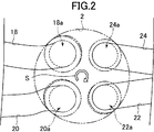
- FIG. 2 is a plan view schematically showing an arrangement of intake ports and exhaust ports in the diesel engine according to an embodiment of the present invention
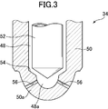
- FIG. 3 is a partial cross-sectional view of the tip portion of the fuel injection valve according to the embodiment of the present invention
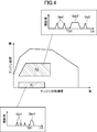
- FIG. 4 shows the fuel set differently depending on the operating state of the diesel engine according to the embodiment of the present invention. It is a figure which shows an example of the injection form.
- reference numeral 1 denotes a diesel engine according to an embodiment of the present invention.
- the diesel engine 1 includes a cylinder block 4 provided with a cylinder 2 (cylinder), and a cylinder head 6 disposed on the cylinder block 4. And an oil pan 8 disposed below the cylinder block 4 and storing lubricating oil.
- a piston 10 is fitted into the cylinder 2 so as to be able to reciprocate, and a cavity 12 is formed on the crown surface 10 a of the piston 10 facing the cylinder head 6 so as to be recessed on the opposite side of the cylinder head 6. .
- the piston 10 is connected to the crankshaft 16 via a connecting rod 14.
- the cylinder head 6 is formed with first and second intake ports 18 and 20 and first and second exhaust ports 22 and 24. These first and second intake ports 18 and 20 open to the surface (lower surface) of the cylinder head 6 on the piston 10 side and one side surface (side surface on the intake side) of the cylinder head 6.
- the two exhaust ports 22 and 24 are open to the piston 10 side surface of the cylinder head 6 and the other side surface (exhaust side surface) of the cylinder head 6.
- the cylinder head 6 includes first and second intake valves 26 and 28 for opening and closing piston-side openings 18a and 20a of the first and second intake ports 18 and 20, respectively, and first and second exhaust ports.
- First and second exhaust valves 30 and 32 for opening and closing the piston side openings 22a and 24a of the ports 22 and 24, respectively, are disposed.
- the cylinder head 6 is provided with a fuel injection valve 34 for injecting fuel and a glow plug 36 for warming intake air to improve the ignitability of the fuel when the diesel engine 1 is cold.
- the fuel injection valve 34 is attached in such a posture that the end on the piston 10 side faces the center of the cavity 12.
- the fuel injection valve 34 is connected to a common rail (not shown) via a fuel supply pipe 38, and fuel is supplied from a fuel tank (not shown) via the fuel supply pipe 38 and the common rail. Excess fuel is returned to the fuel tank through the return pipe 40.
- An intake passage 42 is connected to the intake side of the cylinder head 6 so as to communicate with the first and second intake ports 18 and 20.
- An air cleaner (not shown) for filtering the intake air is disposed at the upstream end of the intake passage 42, and the intake air filtered by the air cleaner passes through the intake passage 42 and the intake ports 18, 20 into the cylinder 2.
- a surge tank 44 is disposed near the downstream end of the intake passage 42.
- the intake passage 42 on the downstream side of the surge tank 44 is formed as independent passages 42a and 42b corresponding to the first and second intake ports 18 and 20, respectively, and the downstream ends of these independent passages 42a and 42b. Are connected to the intake ports 18 and 20 of the cylinder 2, respectively.
- An exhaust passage 46 for discharging burned gas (exhaust gas) from the cylinder 2 is connected to the side surface of the cylinder head 6 on the exhaust side.
- the upstream portion of the exhaust passage 46 is formed as independent passages 46a and 46b that branch corresponding to the first and second exhaust ports 22 and 24, respectively, and the upstream ends of these independent passages 46a and 46b are exhaust ports. 22 and 24, respectively.
- the piston side openings 18a, 20a of the first and second intake ports 18, 20 and the piston side openings 22a, 24a of the first and second exhaust ports 22, 24 are arranged at the center of the cylinder 2.
- the piston side opening 18a of the first intake port 18 and the piston of the second exhaust port 24 are clockwise.
- the side opening 24 a and the piston side opening 22 a of the first exhaust port 22 are arranged in this order.
- a clockwise intake swirl flow S (a lateral vortex flowing around the central axis of the cylinder 2) is generated in the intake stroke as viewed from above.
- the first intake port 18 causes the intake air flowing into the cylinder 2 from the piston side opening 18a to flow in the circumferential direction of the cylinder 2 (the intake air flowing in the vicinity of the piston side opening 18a of the first intake port 18). It is formed as a so-called tangential port directed in the direction of travel of the swirl flow S).
- the second intake port 20 is formed as a so-called helical port for allowing intake air to flow into the cylinder 2 from the piston side opening 20a in a spiral shape.
- the fuel injection valve 34 can be advanced and retracted into a tubular valve body 50 in which a fuel flow path 48 into which fuel is introduced from a common rail is formed, and in the fuel flow path 48 of the valve body 50.
- a needle valve 52 disposed on the surface.
- the valve body 50 has a hemispherical tip 50a, and the end of the fuel flow path 48 corresponding to the tip 50a is a hemispherical sub chamber 48a.
- a seat portion 54 is formed on the inner surface of the valve body 50 around the sub chamber 48a. The seat portion 54 is seated when the needle valve 52 is advanced.
- a plurality of nozzle holes 56 are provided at the tip 50a of the valve body 50.
- Each nozzle hole 56 is provided so as to penetrate the distal end portion 50a, and communicates the surface of the distal end portion 50a of the valve body 50 with the sub chamber 48a.
- a total of ten nozzle holes 56 are provided in the distal end portion 50a, and the nozzle holes 56 are arranged so as to be arranged at substantially equal intervals in the circumferential direction.
- the valve body 50 is provided with a solenoid (not shown), and the needle valve 52 is driven forward and backward by the suction force of the solenoid.
- the needle valve 52 is driven forward and seated on the seat portion 54, the introduction of fuel into the sub chamber 48a is blocked, and the fuel injection from each nozzle hole 56 is stopped.
- the needle valve 52 is driven backward from this state (FIG. 3 shows this state)
- fuel is introduced into the sub chamber 48a, and fuel injection from each injection hole 56 is started. By controlling the time during which the needle valve 52 is driven backward, the fuel injection amount can be adjusted.
- the fuel injection valve 34 is attached coaxially with the cylinder 2. That is, if a straight line extending in the vertical direction through the center of the tip 50a of the valve body 50 is defined as the central axis of the fuel injection valve 34, the fuel injection valve 34 is in such a posture that the central axis coincides with the central axis of the cylinder 2. Is attached.
- the fuel injection valve 34 is divided into three pre-injections Qp1 and one main injection Qm1. Fuel is injected. In the main injection Qm1, fuel injection is started near the compression top dead center (top dead center at the end of the compression stroke), and the injection amount is set to about 1 to 5 mm 3 . In the pre-injection Qp1, a smaller amount of fuel than the main injection Qm1 is injected before the compression top dead center.
- the pre-injection Qp2, the main injection Qm2, and the after-injection Qa2 are divided into two. Fuel is injected from the fuel injection valve 34. In the main injection Qm2, fuel injection is started near the compression top dead center, and the injection amount is set to about 10 to 30 mm 3 . In the pre-injection Qp2, a smaller amount of fuel than the main injection Qm2 is injected before the compression top dead center. In the after-injection Qa2, a smaller amount of fuel than the main injection Qm2 is injected after the main injection Qm2 ends (during the expansion stroke).
- PCM Powertrain Control Module
- the PCM sequentially determines the operating state of the engine based on signals input from various sensors such as an airflow sensor, an engine rotation speed sensor, an accelerator opening sensor (not shown), and is preset for each operating state.
- the fuel injection valve 34 is controlled so as to conform to the target injection form.
- FIGS. 5 is a perspective view of the piston 10 according to the embodiment of the present invention
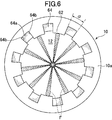
- FIG. 6 is a plan view of the piston 10 shown in FIG. 5
- FIG. 7 is a view taken along VII-VII in FIG. 8 is a partial cross-sectional view of the piston 10 and the cylinder head 6 and the like
- FIG. 8 is a partial cross-sectional view of the piston 10 and the cylinder head 6 and the like seen along VIII-VIII in FIG. 7 and 8 show the piston 10 ascended to the top dead center
- FIGS. 6 and 7 show the fuel spray injected from the injection hole 56 of the fuel injection valve 34 as a reference symbol F.
- the cavity 12 is formed in a shape and size capable of receiving the fuel (spray F) injected from the fuel injection valve 34 at least when the piston 10 is at the top dead center. Yes.
- the cavity 12 is a so-called reentrant type cavity. That is, the wall surface forming the cavity 12 includes a substantially mountain-shaped central raised portion 58, a peripheral concave portion 60 formed in a radial direction outside the central raised portion 58 in the radial direction of the piston 10, a peripheral concave portion 60, and a piston. 10 lip portions 62 having a circular shape in plan view formed between the ten crown surfaces 10a (that is, the peripheral edge of the cavity 12).
- the central raised portion 58 is raised so as to be closer to the fuel injection valve 34 toward the center of the cavity 12, and is formed so that the top of the raised portion is located directly below the distal end portion 50 a of the fuel injection valve 34.
- the peripheral recessed portion 60 is continuous with the central raised portion 58 and is formed to have an arc shape that is recessed radially outward of the piston 10 in a sectional view.
- the lip 62 is continuous with the peripheral recess 60 and is formed in an arc shape that protrudes radially inward of the piston 10 in a sectional view as shown in FIG.
- Each injection hole 56 of the fuel injection valve 34 is directed near the connection portion between the lip portion 62 and the peripheral recess 60.
- the lip portion 62 is formed with a plurality of notches 64 that are recessed from the peripheral edge of the cavity 12 to the radially outer side of the piston 10.
- Each notch 64 is disposed between the directivity directions of the nozzle hole 56 of the fuel injection valve 34.
- a total of ten injection holes 56 are arranged so as to be arranged at substantially equal intervals in the circumferential direction, and fuel is injected radially in plan view. Therefore, as shown in FIG. 6, in this embodiment, a total of ten notches 64 are arranged so as to be arranged at substantially equal intervals in the circumferential direction between the directivity directions of the injection holes 56 of the fuel injection valve 34. ing.
- the notch 64 is formed in a substantially rectangular concave shape that is recessed radially outward of the piston 10 from the tip of the lip 62 that protrudes radially inward of the piston 10 in plan view. . That is, the wall surface forming the notch 64 has a bottom surface 64a extending along the circumferential direction of the piston 10 in plan view, and two side surfaces 64b extending from both ends of the bottom surface 64a inward in the radial direction of the piston 10. Yes.
- a central angle ⁇ (corresponding to the width of the notch 64) formed by a straight line connecting the center of the piston 10 and both ends of the bottom surface 64a of the notch 64 in plan view is, for example, 14 ° in the present embodiment.
- the bottom surface 64 a of the notch 64 is inclined outward in the radial direction of the piston 10 from the bottom surface 64 a of the cavity 12 toward the crown surface 10 a of the piston 10 in a cross-sectional view.
- the angle (mortar angle) ⁇ formed by the bottom surface 64a of the notch 64 and the axial direction of the piston 10 is, for example, 30 ° in the present embodiment.
- the end of the bottom surface 64 a of the notch 64 on the peripheral recess 60 side is continuous with the periphery of the peripheral recess 60.
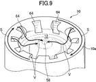
- FIG. 9 is a perspective view conceptually showing air flow in the combustion chamber according to the embodiment of the present invention
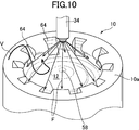
- FIG. 10 is a perspective view conceptually showing fuel spray and air flow in the combustion chamber according to the embodiment of the present invention.
- the intake swirl flow S that is clockwise when viewed from the upper side in the intake stroke is generated in the cylinder 2, and the intake swirl flow S in the cylinder 2 is generated by the first and second intake ports 18 and 20. Will be strengthened.
- an intake swirl flow S (a lateral vortex flowing around the central axis of the cylinder 2) that flows on the radially outer side of the piston 10 above the cavity 12 above the piston crown surface 10a is cut off as shown in FIG. It falls from the notch 64 to the peripheral recess 60 of the cavity 12 and advances inward in the radial direction of the piston 10 along the central raised portion 58.
- an air flow V having a velocity component in the radial direction of the piston 10 is generated in addition to the lateral vortex flowing around the central axis of the cylinder 2 due to the intake swirl flow S.
- the velocity component in the radial direction of the piston 10 of the air flow V flowing along the peripheral recess 60 reaches about three times that when the notch 64 is not provided.
- the fuel injection valve 34 When the compression stroke progresses and fuel injection is performed by the fuel injection valve 34 near the compression top dead center, the fuel injected from the injection hole 56 reaches the vicinity of the connection portion between the lip portion 62 and the peripheral recess 60. In the low load region such as the operation region A1 in FIG. 4, the amount of fuel injected from the fuel injection valve 34 is small, so that the fuel spray F reaches the vicinity of the connection portion between the lip portion 62 and the peripheral recess 60. It is slowing down considerably. Therefore, the flow in which the spray F is reversed radially inward along the wall surface of the cavity 12 hardly occurs depending on the momentum of the spray F itself.
- the amount of fuel injected from the fuel injection valve 34 is large, so that the spray F has a diameter along the wall surface of the cavity 12. Inverted in the direction, flows toward the center of the piston 10 along the wall surface of the cavity 12, and reacts with air and burns in the process. At this time, if the penetration of the fuel spray F is weakened to reduce the cooling loss in the low load region, the flow of the spray F toward the center side of the cavity 12 becomes weak. However, when the intake swirl flow S falls from the notch 64 to the peripheral recess 60 of the cavity 12, an air flow V having a velocity component in the radial direction of the piston 10 exists in the cavity 12.
- the spray F that has reached the vicinity of the connection portion between the lip 62 and the peripheral recess 60 merges with the air flow V while reversing radially inward along the wall surface of the cavity 12. Mix with.
- the mixing property of the fuel spray F and the air can be improved without increasing the penetration of the fuel spray F in the middle / high load region, and the amount of NOx and soot (soot) generated can be reduced.
- the central angle ⁇ formed by a straight line connecting the center of the piston 10 and both ends of the bottom surface 64a of the notch 64 in plan view is, for example, 14 °, and the bottom surface 64a of the notch 64 and the piston 10
- the angle (mortar angle) ⁇ formed with the axial direction is 30 °, for example, the notch 64 may be formed with a dimension different from this.
- the fuel injection valve 34 having ten injection holes 27 is shown.
- the present invention is also applicable to an engine having the fuel injection valves 34 having a plurality of different injection holes 27. Is possible.
- a notch 64 is formed in the crown surface 10a of the piston 10 so as to be recessed from the peripheral edge of the cavity 12 to the radially outer side of the piston 10, the piston 10 is located above the piston crown surface 10a rather than the cavity 12.
- the swirl flow S that flows radially outward flows into the cavity 12 from the notch 64, and an air flow that travels radially inward of the piston 10 along the wall surface of the cavity 12 is generated.
- the air flow having the velocity component in the radial direction of the piston 10 is generated, so that the cavity of the fuel spray F is not strengthened.
- the fluidity of the air in the air can be increased, and both the reduction of the cooling loss and the improvement of the mixing ability of the fuel spray F and the air can be achieved.
- the fuel injection valve 34 is formed with a plurality of injection holes 56 directed in the cavity 12 so as to spray fuel radially in the cavity 12 in a plan view.
- the flow of the fuel sprayed on the fuel can be accelerated by the air flow having the velocity component in the radial direction of the piston 10, and the mixing ability of the fuel spray F and air can be further improved without increasing the penetration of the fuel spray F. Can do.
- the notches 64 are disposed between the directivity directions of the plurality of nozzle holes 56, the notches 64 are sprayed radially into the cavity 12 in a plan view, and the radial direction of the piston 10 along the wall surface of the cavity 12.
- the fuel flow reversed inward and the air flow having the velocity component in the radial direction of the piston 10 generated by the swirl flow S flowing into the cavity 12 from the notch 64 are merged, and the fuel in the cavity 12 is merged.
- the mixing of the fuel spray F and the air can be further improved without increasing the penetration of the fuel spray F.
- a plurality of notches 64 that are recessed radially outward of the piston 10 are formed in the lip 62 that is formed at the periphery of the cavity 12 of the piston crown surface 10a and protrudes radially inward of the piston 10. Air that flows radially outward of the piston 10 above the cavity 12 above the piston crown surface 10 a flows into the cavity 12 from the notch 64 and travels radially inward of the piston 10 along the wall surface of the cavity 12. Flow occurs. Thereby, the fluidity
- the notches 64 are disposed between the directivity directions of the injection holes 56 of the fuel injection valve 34, the notches 64 are sprayed radially into the cavity 12 in a plan view, and the diameter of the piston 10 along the lip portion 62.
- the flow of the fuel that is reversed inward in the direction and the air flow having the velocity component in the radial direction of the piston 10 that has flowed into the cavity 12 from the notch 64 are merged to promote mixing of fuel and air in the cavity 12. can do.
- the fluidity of the air in the cavity 12 can be increased without increasing the penetration of the fuel spray F, and both the reduction of the cooling loss and the improvement of the mixability of the fuel spray F and air can be achieved.
- the injection hole 56 is directed to the opposite side of the cylinder head 6 from the tip of the lip portion 62 in the radial direction of the piston 10, the fuel injected from the fuel injection valve 34 is more than the tip of the lip portion 62.
- the fuel injection valve 34 On the side opposite to the cylinder head 6, it is inverted radially inward of the piston 10 along the wall surface of the cavity 12 and flows toward the center side of the piston 10, so that the fuel flows from the notch 64 in the same direction. It is possible to generate an air flow having a velocity component in the radial direction of the piston 10 that has flowed into the cavity 12, thereby further promoting the mixing of fuel and air in the cavity 12.
- the wall surface forming the cavity 12 has the central raised portion 58 that protrudes closer to the fuel injection valve 34 toward the center of the cavity 12, the wall surface of the cavity 12 is inverted radially inward along the wall surface of the cavity 12.
- the mixing of fuel and air in the cavity 12 can be further promoted.
Landscapes
- Engineering & Computer Science (AREA)
- Chemical & Material Sciences (AREA)
- Combustion & Propulsion (AREA)
- Mechanical Engineering (AREA)
- General Engineering & Computer Science (AREA)
- Combustion Methods Of Internal-Combustion Engines (AREA)
- Cylinder Crankcases Of Internal Combustion Engines (AREA)
Abstract
Moteur diesel pouvant à la fois de réduire la perte de refroidissement et améliorer les propriétés de mélange entre un brouillard de pulvérisation de carburant et de l'air grâce à l'augmentation de l'aptitude à l'écoulement de l'air à l'intérieur d'une cavité sans augmenter la pénétration du brouillard de pulvérisation de carburant. Dans une surface de couronne (10a) d'un piston (10) de ce moteur diesel (1) est formée une cavité (12) qui est en retrait vers le côté opposé à une culasse (6), et qui est circulaire sur une vue en plan. Une surface de paroi formant la cavité comporte une partie lèvre (62) qui est formée au niveau du bord circonférentiel de la cavité et qui fait saillie vers le côté intérieur dans la direction radiale du piston. Dans la partie lèvre sont formées une pluralité de parties découpées (64) en retrait depuis le bord circonférentiel de la cavité vers le côté extérieur dans la direction radiale du piston. Une soupape d'injection de carburant (34) est agencée au centre de la culasse, et comporte, formés dans celle-ci, une pluralité de trous d'injection (56) orientés chacun vers l'intérieur de la cavité de façon à pulvériser un carburant dans la cavité radialement sur une vue en plan. Les parties découpées sont chacune agencées entre les directions d'orientation respectives des trous d'injection.
Priority Applications (4)
| Application Number | Priority Date | Filing Date | Title |
|---|---|---|---|
| EP16922530.7A EP3530905A4 (fr) | 2016-11-22 | 2016-11-22 | Moteur diesel |
| PCT/JP2016/084628 WO2018096592A1 (fr) | 2016-11-22 | 2016-11-22 | Moteur diesel |
| JP2018552300A JPWO2018096592A1 (ja) | 2016-11-22 | 2016-11-22 | ディーゼルエンジン |
| US16/461,324 US20200080468A1 (en) | 2016-11-22 | 2016-11-22 | Diesel engine |
Applications Claiming Priority (1)
| Application Number | Priority Date | Filing Date | Title |
|---|---|---|---|
| PCT/JP2016/084628 WO2018096592A1 (fr) | 2016-11-22 | 2016-11-22 | Moteur diesel |
Publications (1)
| Publication Number | Publication Date |
|---|---|
| WO2018096592A1 true WO2018096592A1 (fr) | 2018-05-31 |
Family
ID=62194893
Family Applications (1)
| Application Number | Title | Priority Date | Filing Date |
|---|---|---|---|
| PCT/JP2016/084628 Ceased WO2018096592A1 (fr) | 2016-11-22 | 2016-11-22 | Moteur diesel |
Country Status (4)
| Country | Link |
|---|---|
| US (1) | US20200080468A1 (fr) |
| EP (1) | EP3530905A4 (fr) |
| JP (1) | JPWO2018096592A1 (fr) |
| WO (1) | WO2018096592A1 (fr) |
Citations (5)
| Publication number | Priority date | Publication date | Assignee | Title |
|---|---|---|---|---|
| JPH0913972A (ja) * | 1995-06-27 | 1997-01-14 | Nissan Diesel Motor Co Ltd | 直接噴射式ディーゼルエンジンの燃焼室 |
| JPH09256851A (ja) * | 1996-03-21 | 1997-09-30 | Daihatsu Motor Co Ltd | 直噴式ディーゼル機関における燃焼室の構造 |
| JP2000274247A (ja) * | 1999-03-19 | 2000-10-03 | Toyota Motor Corp | ディーゼルエンジン |
| JP2015105570A (ja) * | 2013-11-28 | 2015-06-08 | 株式会社豊田中央研究所 | ディーゼルエンジン |
| JP2015232288A (ja) | 2014-06-09 | 2015-12-24 | マツダ株式会社 | ディーゼルエンジン |
Family Cites Families (50)
| Publication number | Priority date | Publication date | Assignee | Title |
|---|---|---|---|---|
| US2231392A (en) * | 1939-01-26 | 1941-02-11 | John J Mccarthy | Internal combustion engine |
| JPS526809A (en) * | 1975-07-05 | 1977-01-19 | Hino Motors Ltd | Combustion chamber for a diesel engine |
| JPS55153816A (en) * | 1979-05-17 | 1980-12-01 | Yanmar Diesel Engine Co Ltd | Combustion chamber of direct injection type diesel engine |
| AT398606B (de) * | 1986-12-12 | 1995-01-25 | Avl Verbrennungskraft Messtech | Luftverdichtende, ventilgesteuerte brennkraftmaschine |
| US5103784A (en) * | 1990-02-07 | 1992-04-14 | The Univeristy Of British Columbia | Squish jet combustion chamber |
| US5065715A (en) * | 1990-02-07 | 1991-11-19 | The University Of British Columbia | Squish jet combustion chamber |
| JPH045428A (ja) * | 1990-04-23 | 1992-01-09 | Isuzu Motors Ltd | 内燃機関の燃焼室構造 |
| WO1991019083A1 (fr) * | 1990-06-04 | 1991-12-12 | Nippon Clean Engine Research Institute Co., Ltd. | Moteur a combustion interne du type a allumage par impact contre une surface chaude et allumage d'un tel moteur par impact du carburant contre une surface chaude |
| US5136994A (en) * | 1991-04-15 | 1992-08-11 | Southwest Research Institute | Internal combustion engine |
| CA2088786C (fr) * | 1991-06-21 | 1998-05-05 | Shigeru Onishi | Moteur a combustion interne, a injection d'huile, du type a injection directe |
| US5224449A (en) * | 1991-10-31 | 1993-07-06 | Osaka Gas Company, Ltd. | Lean-burn internal combustion system |
| JPH05202755A (ja) * | 1992-01-27 | 1993-08-10 | Hino Motors Ltd | ディーゼルエンジン |
| JPH10299537A (ja) * | 1997-04-28 | 1998-11-10 | Mazda Motor Corp | 筒内噴射型火花点火式エンジン |
| JP3353709B2 (ja) * | 1998-07-08 | 2002-12-03 | トヨタ自動車株式会社 | 筒内噴射式火花点火内燃機関 |
| US6237579B1 (en) * | 1999-01-26 | 2001-05-29 | Somender Singh | Design to improve turbulence in combustion chambers |
| DE10063568A1 (de) * | 2000-12-20 | 2002-07-04 | Mahle Gmbh | Kühlkanalkolben für einen Dieselmotor mit Direkteinspritzung mit einem Kolbendurchmesser von 100 mm |
| US6601561B1 (en) * | 2002-01-30 | 2003-08-05 | International Engine Intellectual Property Company, Llc | Combustion chamber |
| JP2003065056A (ja) * | 2001-08-24 | 2003-03-05 | Toyota Motor Corp | 筒内噴射式火花点火内燃機関 |
| US6708666B2 (en) * | 2001-10-10 | 2004-03-23 | Southwest Research Institute | Multi-zone combustion chamber for combustion rate shaping and emissions control in premixed-charge combustion engines |
| JP2003286879A (ja) * | 2002-03-27 | 2003-10-10 | Mazda Motor Corp | ディーゼルエンジンの燃焼制御装置 |
| DE10221561A1 (de) * | 2002-05-15 | 2004-01-08 | Mahle Gmbh | Gekühlter Kolben für einen Verbrennungsmotor |
| US6739308B1 (en) * | 2002-05-24 | 2004-05-25 | Hatch & Kirk, Inc. | Fuel igniter and head for use in diesel engines and related systems and methods |
| US6701875B2 (en) * | 2002-05-31 | 2004-03-09 | Cummins Inc. | Internal combustion engine with piston cooling system and piston therefor |
| US6955165B2 (en) * | 2003-03-13 | 2005-10-18 | International Engine Intellectual Property Company, Llc | Three-reentrancy combustion chamber |
| KR101130637B1 (ko) * | 2003-12-01 | 2012-04-02 | 가부시키가이샤 고마쓰 세이사쿠쇼 | 연료 직접 분사식 디젤 엔진 |
| US6997158B1 (en) * | 2004-10-07 | 2006-02-14 | International Engine Intellectual Property Company, Llc | Diesel combustion chamber |
| JP2006112312A (ja) * | 2004-10-14 | 2006-04-27 | Yanmar Co Ltd | 直噴式ディーゼル機関の燃焼室形状 |
| US7185614B2 (en) * | 2004-10-28 | 2007-03-06 | Caterpillar Inc | Double bowl piston |
| EP1701027B1 (fr) * | 2005-03-11 | 2016-12-28 | Ford Global Technologies, Inc. | Méthode d'utilisation en mode de l'auto allumage de charge homogène partiel dans un moteur diesel pour régénérer un piège à NOx |
| FR2886982A1 (fr) * | 2005-06-09 | 2006-12-15 | Renault Sas | Piston pour moteur a injection directe |
| FR2894614B1 (fr) * | 2005-12-08 | 2008-02-29 | Renault Sas | Moteur a combustion interne comportant un piston comportant un bossage de geometrie complexe |
| FR2895026B1 (fr) * | 2005-12-21 | 2011-09-09 | Inst Francais Du Petrole | Procede d'injection de carburant pour moteur a combustion interne,notamment a injection directe, comportant un piston muni d'un bol avec un teton |
| US7318406B2 (en) * | 2006-04-10 | 2008-01-15 | Ford Global Technologies Llc | Bowl-in-piston of a cylinder in a direct injection engine |
| JP4888330B2 (ja) * | 2007-10-22 | 2012-02-29 | トヨタ自動車株式会社 | 直接噴射式の内燃機関 |
| BRPI0722151B1 (pt) * | 2007-10-30 | 2019-10-29 | Volvo Lastvagnar Ab | dispositivo para redução de emissões em um motor de combustão interna de veículo |
| US20090188481A1 (en) * | 2008-01-29 | 2009-07-30 | Detroit Diesel Corporation | Squish-induced mixing-intensified low emissions combustion piston for internal combustion engines |
| US8776760B2 (en) * | 2009-10-13 | 2014-07-15 | Southwest Research Institute | Combustion chamber for fuel injected engines |
| US8291881B2 (en) * | 2009-12-22 | 2012-10-23 | Perkins Engine Company Limited | Piston for internal combustion engine |
| US9279361B2 (en) * | 2010-04-20 | 2016-03-08 | Southwest Research Institute | Piston bowl with spray jet targets |
| US8459229B2 (en) * | 2010-04-20 | 2013-06-11 | Southwest Research Institute | Piston bowl with spray jet targets |
| US8555854B2 (en) * | 2010-04-26 | 2013-10-15 | Southwest Research Institute | Piston bowl with deflecting features |
| US8677974B2 (en) * | 2010-05-04 | 2014-03-25 | Southwest Research Institute | Piston bowl with flat bottom |
| DE102012103212A1 (de) * | 2012-04-13 | 2013-10-17 | Mwm Gmbh | Kolben einer Brennkraftmaschine |
| DE102012103195A1 (de) * | 2012-04-13 | 2013-10-17 | Mwm Gmbh | Kolben einer Brennkraftmaschine |
| DE102012103206B4 (de) * | 2012-04-13 | 2017-08-03 | Caterpillar Energy Solutions Gmbh | Kolben einer Brennkraftmaschine |
| JP6100916B2 (ja) * | 2012-12-18 | 2017-03-22 | ボルボ トラック コーポレイション | 内燃機関のシリンダのためのピストン |
| US10072561B2 (en) * | 2016-07-25 | 2018-09-11 | Caterpillar Inc. | Piston |
| JP6304351B1 (ja) * | 2016-11-22 | 2018-04-04 | マツダ株式会社 | ディーゼルエンジン |
| JP6477750B2 (ja) * | 2017-03-10 | 2019-03-06 | マツダ株式会社 | ディーゼルエンジン |
| KR102463187B1 (ko) * | 2017-07-28 | 2022-11-03 | 현대자동차 주식회사 | 피스톤 및 이를 포함하는 엔진 |
-
2016
- 2016-11-22 WO PCT/JP2016/084628 patent/WO2018096592A1/fr not_active Ceased
- 2016-11-22 JP JP2018552300A patent/JPWO2018096592A1/ja active Pending
- 2016-11-22 EP EP16922530.7A patent/EP3530905A4/fr not_active Withdrawn
- 2016-11-22 US US16/461,324 patent/US20200080468A1/en not_active Abandoned
Patent Citations (5)
| Publication number | Priority date | Publication date | Assignee | Title |
|---|---|---|---|---|
| JPH0913972A (ja) * | 1995-06-27 | 1997-01-14 | Nissan Diesel Motor Co Ltd | 直接噴射式ディーゼルエンジンの燃焼室 |
| JPH09256851A (ja) * | 1996-03-21 | 1997-09-30 | Daihatsu Motor Co Ltd | 直噴式ディーゼル機関における燃焼室の構造 |
| JP2000274247A (ja) * | 1999-03-19 | 2000-10-03 | Toyota Motor Corp | ディーゼルエンジン |
| JP2015105570A (ja) * | 2013-11-28 | 2015-06-08 | 株式会社豊田中央研究所 | ディーゼルエンジン |
| JP2015232288A (ja) | 2014-06-09 | 2015-12-24 | マツダ株式会社 | ディーゼルエンジン |
Non-Patent Citations (1)
| Title |
|---|
| See also references of EP3530905A4 |
Also Published As
| Publication number | Publication date |
|---|---|
| JPWO2018096592A1 (ja) | 2019-10-17 |
| EP3530905A4 (fr) | 2019-10-23 |
| US20200080468A1 (en) | 2020-03-12 |
| EP3530905A1 (fr) | 2019-08-28 |
Similar Documents
| Publication | Publication Date | Title |
|---|---|---|
| JP6481968B2 (ja) | ディーゼルエンジン | |
| JP6160564B2 (ja) | ディーゼルエンジン | |
| US7225791B2 (en) | Compression-ignition internal combustion engine | |
| EP2187017B1 (fr) | Moteur diesel, piston pour moteur diesel et procédé de fabrication de moteur diesel | |
| US20130047950A1 (en) | Piston positioned for reciprocal movement in a combustion engine cylinder | |
| RU2490486C2 (ru) | Камера сгорания для теплового двигателя с прямым вспрыском и с наддувом | |
| CN106939842A (zh) | 燃料喷射装置 | |
| US7165526B2 (en) | Direct injection engine and controller for the same | |
| JP2014148947A (ja) | ディーゼルエンジン | |
| JP6786059B2 (ja) | ディーゼルエンジン | |
| US10125667B2 (en) | Structure of combustion chamber for direct injection engine | |
| JP5971321B2 (ja) | 直噴エンジンの燃焼室構造 | |
| RU2686359C2 (ru) | Многоструйный инжектор с последовательным впрыском топлива | |
| JP6551868B2 (ja) | ディーゼルエンジン | |
| JP6519633B2 (ja) | エンジンの燃焼室構造 | |
| JP6481703B2 (ja) | ディーゼルエンジン | |
| WO2019044647A1 (fr) | Structure de chambre de combustion de moteur | |
| US10385802B2 (en) | Piston of internal combustion engine | |
| WO2018096591A1 (fr) | Moteur diesel | |
| WO2018096592A1 (fr) | Moteur diesel | |
| JP2017025929A (ja) | ディーゼルエンジンの燃焼室構造 | |
| JP4888092B2 (ja) | ロータリピストンエンジンの燃料噴射装置 | |
| JP2020012432A (ja) | 内燃機関 |
Legal Events
| Date | Code | Title | Description |
|---|---|---|---|
| 121 | Ep: the epo has been informed by wipo that ep was designated in this application |
Ref document number: 16922530 Country of ref document: EP Kind code of ref document: A1 |
|
| ENP | Entry into the national phase |
Ref document number: 2018552300 Country of ref document: JP Kind code of ref document: A |
|
| NENP | Non-entry into the national phase |
Ref country code: DE |
|
| ENP | Entry into the national phase |
Ref document number: 2016922530 Country of ref document: EP Effective date: 20190523 |