WO2018096660A1 - Dispositif de remplissage automatique - Google Patents
Dispositif de remplissage automatique Download PDFInfo
- Publication number
- WO2018096660A1 WO2018096660A1 PCT/JP2016/085023 JP2016085023W WO2018096660A1 WO 2018096660 A1 WO2018096660 A1 WO 2018096660A1 JP 2016085023 W JP2016085023 W JP 2016085023W WO 2018096660 A1 WO2018096660 A1 WO 2018096660A1
- Authority
- WO
- WIPO (PCT)
- Prior art keywords
- insert
- dispenser
- edge
- injection hole
- automatic filling
- Prior art date
- Legal status (The legal status is an assumption and is not a legal conclusion. Google has not performed a legal analysis and makes no representation as to the accuracy of the status listed.)
- Ceased
Links
Images




Classifications
-
- B—PERFORMING OPERATIONS; TRANSPORTING
- B29—WORKING OF PLASTICS; WORKING OF SUBSTANCES IN A PLASTIC STATE IN GENERAL
- B29C—SHAPING OR JOINING OF PLASTICS; SHAPING OF MATERIAL IN A PLASTIC STATE, NOT OTHERWISE PROVIDED FOR; AFTER-TREATMENT OF THE SHAPED PRODUCTS, e.g. REPAIRING
- B29C70/00—Shaping composites, i.e. plastics material comprising reinforcements, fillers or preformed parts, e.g. inserts
- B29C70/68—Shaping composites, i.e. plastics material comprising reinforcements, fillers or preformed parts, e.g. inserts by incorporating or moulding on preformed parts, e.g. inserts or layers, e.g. foam blocks
- B29C70/86—Incorporated in coherent impregnated reinforcing layers, e.g. by winding
-
- B—PERFORMING OPERATIONS; TRANSPORTING
- B29—WORKING OF PLASTICS; WORKING OF SUBSTANCES IN A PLASTIC STATE IN GENERAL
- B29C—SHAPING OR JOINING OF PLASTICS; SHAPING OF MATERIAL IN A PLASTIC STATE, NOT OTHERWISE PROVIDED FOR; AFTER-TREATMENT OF THE SHAPED PRODUCTS, e.g. REPAIRING
- B29C65/00—Joining or sealing of preformed parts, e.g. welding of plastics materials; Apparatus therefor
- B29C65/48—Joining or sealing of preformed parts, e.g. welding of plastics materials; Apparatus therefor using adhesives, i.e. using supplementary joining material; solvent bonding
- B29C65/52—Joining or sealing of preformed parts, e.g. welding of plastics materials; Apparatus therefor using adhesives, i.e. using supplementary joining material; solvent bonding characterised by the way of applying the adhesive
- B29C65/54—Joining or sealing of preformed parts, e.g. welding of plastics materials; Apparatus therefor using adhesives, i.e. using supplementary joining material; solvent bonding characterised by the way of applying the adhesive between pre-assembled parts
- B29C65/542—Joining or sealing of preformed parts, e.g. welding of plastics materials; Apparatus therefor using adhesives, i.e. using supplementary joining material; solvent bonding characterised by the way of applying the adhesive between pre-assembled parts by injection
-
- B—PERFORMING OPERATIONS; TRANSPORTING
- B05—SPRAYING OR ATOMISING IN GENERAL; APPLYING FLUENT MATERIALS TO SURFACES, IN GENERAL
- B05C—APPARATUS FOR APPLYING FLUENT MATERIALS TO SURFACES, IN GENERAL
- B05C5/00—Apparatus in which liquid or other fluent material is projected, poured or allowed to flow on to the surface of the work
- B05C5/02—Apparatus in which liquid or other fluent material is projected, poured or allowed to flow on to the surface of the work the liquid or other fluent material being discharged through an outlet orifice by pressure, e.g. from an outlet device in contact or almost in contact, with the work
-
- B—PERFORMING OPERATIONS; TRANSPORTING
- B32—LAYERED PRODUCTS
- B32B—LAYERED PRODUCTS, i.e. PRODUCTS BUILT-UP OF STRATA OF FLAT OR NON-FLAT, e.g. CELLULAR OR HONEYCOMB, FORM
- B32B15/00—Layered products comprising a layer of metal
- B32B15/04—Layered products comprising a layer of metal comprising metal as the main or only constituent of a layer, which is next to another layer of the same or of a different material
-
- B—PERFORMING OPERATIONS; TRANSPORTING
- B32—LAYERED PRODUCTS
- B32B—LAYERED PRODUCTS, i.e. PRODUCTS BUILT-UP OF STRATA OF FLAT OR NON-FLAT, e.g. CELLULAR OR HONEYCOMB, FORM
- B32B15/00—Layered products comprising a layer of metal
- B32B15/20—Layered products comprising a layer of metal comprising aluminium or copper
-
- B—PERFORMING OPERATIONS; TRANSPORTING
- B32—LAYERED PRODUCTS
- B32B—LAYERED PRODUCTS, i.e. PRODUCTS BUILT-UP OF STRATA OF FLAT OR NON-FLAT, e.g. CELLULAR OR HONEYCOMB, FORM
- B32B27/00—Layered products comprising a layer of synthetic resin
- B32B27/06—Layered products comprising a layer of synthetic resin as the main or only constituent of a layer, which is next to another layer of the same or of a different material
-
- B—PERFORMING OPERATIONS; TRANSPORTING
- B32—LAYERED PRODUCTS
- B32B—LAYERED PRODUCTS, i.e. PRODUCTS BUILT-UP OF STRATA OF FLAT OR NON-FLAT, e.g. CELLULAR OR HONEYCOMB, FORM
- B32B3/00—Layered products comprising a layer with external or internal discontinuities or unevennesses, or a layer of non-planar shape; Layered products comprising a layer having particular features of form
- B32B3/02—Layered products comprising a layer with external or internal discontinuities or unevennesses, or a layer of non-planar shape; Layered products comprising a layer having particular features of form characterised by features of form at particular places, e.g. in edge regions
- B32B3/08—Layered products comprising a layer with external or internal discontinuities or unevennesses, or a layer of non-planar shape; Layered products comprising a layer having particular features of form characterised by features of form at particular places, e.g. in edge regions characterised by added members at particular parts
-
- B—PERFORMING OPERATIONS; TRANSPORTING
- B32—LAYERED PRODUCTS
- B32B—LAYERED PRODUCTS, i.e. PRODUCTS BUILT-UP OF STRATA OF FLAT OR NON-FLAT, e.g. CELLULAR OR HONEYCOMB, FORM
- B32B3/00—Layered products comprising a layer with external or internal discontinuities or unevennesses, or a layer of non-planar shape; Layered products comprising a layer having particular features of form
- B32B3/10—Layered products comprising a layer with external or internal discontinuities or unevennesses, or a layer of non-planar shape; Layered products comprising a layer having particular features of form characterised by a discontinuous layer, i.e. formed of separate pieces of material
- B32B3/12—Layered products comprising a layer with external or internal discontinuities or unevennesses, or a layer of non-planar shape; Layered products comprising a layer having particular features of form characterised by a discontinuous layer, i.e. formed of separate pieces of material characterised by a layer of regularly- arranged cells, e.g. a honeycomb structure
-
- B—PERFORMING OPERATIONS; TRANSPORTING
- B32—LAYERED PRODUCTS
- B32B—LAYERED PRODUCTS, i.e. PRODUCTS BUILT-UP OF STRATA OF FLAT OR NON-FLAT, e.g. CELLULAR OR HONEYCOMB, FORM
- B32B3/00—Layered products comprising a layer with external or internal discontinuities or unevennesses, or a layer of non-planar shape; Layered products comprising a layer having particular features of form
- B32B3/26—Layered products comprising a layer with external or internal discontinuities or unevennesses, or a layer of non-planar shape; Layered products comprising a layer having particular features of form characterised by a particular shape of the outline of the cross-section of a continuous layer; characterised by a layer with cavities or internal voids ; characterised by an apertured layer
- B32B3/266—Layered products comprising a layer with external or internal discontinuities or unevennesses, or a layer of non-planar shape; Layered products comprising a layer having particular features of form characterised by a particular shape of the outline of the cross-section of a continuous layer; characterised by a layer with cavities or internal voids ; characterised by an apertured layer characterised by an apertured layer, the apertures going through the whole thickness of the layer, e.g. expanded metal, perforated layer, slit layer regular cells B32B3/12
-
- B—PERFORMING OPERATIONS; TRANSPORTING
- B32—LAYERED PRODUCTS
- B32B—LAYERED PRODUCTS, i.e. PRODUCTS BUILT-UP OF STRATA OF FLAT OR NON-FLAT, e.g. CELLULAR OR HONEYCOMB, FORM
- B32B3/00—Layered products comprising a layer with external or internal discontinuities or unevennesses, or a layer of non-planar shape; Layered products comprising a layer having particular features of form
- B32B3/26—Layered products comprising a layer with external or internal discontinuities or unevennesses, or a layer of non-planar shape; Layered products comprising a layer having particular features of form characterised by a particular shape of the outline of the cross-section of a continuous layer; characterised by a layer with cavities or internal voids ; characterised by an apertured layer
- B32B3/30—Layered products comprising a layer with external or internal discontinuities or unevennesses, or a layer of non-planar shape; Layered products comprising a layer having particular features of form characterised by a particular shape of the outline of the cross-section of a continuous layer; characterised by a layer with cavities or internal voids ; characterised by an apertured layer characterised by a layer formed with recesses or projections, e.g. hollows, grooves, protuberances, ribs
-
- B—PERFORMING OPERATIONS; TRANSPORTING
- B32—LAYERED PRODUCTS
- B32B—LAYERED PRODUCTS, i.e. PRODUCTS BUILT-UP OF STRATA OF FLAT OR NON-FLAT, e.g. CELLULAR OR HONEYCOMB, FORM
- B32B7/00—Layered products characterised by the relation between layers; Layered products characterised by the relative orientation of features between layers, or by the relative values of a measurable parameter between layers, i.e. products comprising layers having different physical, chemical or physicochemical properties; Layered products characterised by the interconnection of layers
- B32B7/04—Interconnection of layers
- B32B7/12—Interconnection of layers using interposed adhesives or interposed materials with bonding properties
-
- C—CHEMISTRY; METALLURGY
- C09—DYES; PAINTS; POLISHES; NATURAL RESINS; ADHESIVES; COMPOSITIONS NOT OTHERWISE PROVIDED FOR; APPLICATIONS OF MATERIALS NOT OTHERWISE PROVIDED FOR
- C09J—ADHESIVES; NON-MECHANICAL ASPECTS OF ADHESIVE PROCESSES IN GENERAL; ADHESIVE PROCESSES NOT PROVIDED FOR ELSEWHERE; USE OF MATERIALS AS ADHESIVES
- C09J5/00—Adhesive processes in general; Adhesive processes not provided for elsewhere, e.g. relating to primers
-
- F—MECHANICAL ENGINEERING; LIGHTING; HEATING; WEAPONS; BLASTING
- F16—ENGINEERING ELEMENTS AND UNITS; GENERAL MEASURES FOR PRODUCING AND MAINTAINING EFFECTIVE FUNCTIONING OF MACHINES OR INSTALLATIONS; THERMAL INSULATION IN GENERAL
- F16B—DEVICES FOR FASTENING OR SECURING CONSTRUCTIONAL ELEMENTS OR MACHINE PARTS TOGETHER, e.g. NAILS, BOLTS, CIRCLIPS, CLAMPS, CLIPS OR WEDGES; JOINTS OR JOINTING
- F16B5/00—Joining sheets or plates, e.g. panels, to one another or to strips or bars parallel to them
-
- B—PERFORMING OPERATIONS; TRANSPORTING
- B29—WORKING OF PLASTICS; WORKING OF SUBSTANCES IN A PLASTIC STATE IN GENERAL
- B29C—SHAPING OR JOINING OF PLASTICS; SHAPING OF MATERIAL IN A PLASTIC STATE, NOT OTHERWISE PROVIDED FOR; AFTER-TREATMENT OF THE SHAPED PRODUCTS, e.g. REPAIRING
- B29C37/00—Component parts, details, accessories or auxiliary operations, not covered by group B29C33/00 or B29C35/00
- B29C37/0078—Measures or configurations for obtaining anchoring effects in the contact areas between layers
- B29C37/0082—Mechanical anchoring
-
- B—PERFORMING OPERATIONS; TRANSPORTING
- B32—LAYERED PRODUCTS
- B32B—LAYERED PRODUCTS, i.e. PRODUCTS BUILT-UP OF STRATA OF FLAT OR NON-FLAT, e.g. CELLULAR OR HONEYCOMB, FORM
- B32B2250/00—Layers arrangement
- B32B2250/40—Symmetrical or sandwich layers, e.g. ABA, ABCBA, ABCCBA
-
- B—PERFORMING OPERATIONS; TRANSPORTING
- B32—LAYERED PRODUCTS
- B32B—LAYERED PRODUCTS, i.e. PRODUCTS BUILT-UP OF STRATA OF FLAT OR NON-FLAT, e.g. CELLULAR OR HONEYCOMB, FORM
- B32B2262/00—Composition or structural features of fibres which form a fibrous or filamentary layer or are present as additives
- B32B2262/10—Inorganic fibres
- B32B2262/106—Carbon fibres, e.g. graphite fibres
-
- B—PERFORMING OPERATIONS; TRANSPORTING
- B32—LAYERED PRODUCTS
- B32B—LAYERED PRODUCTS, i.e. PRODUCTS BUILT-UP OF STRATA OF FLAT OR NON-FLAT, e.g. CELLULAR OR HONEYCOMB, FORM
- B32B2307/00—Properties of the layers or laminate
- B32B2307/70—Other properties
- B32B2307/732—Dimensional properties
Definitions
- the present invention relates to a technique for automatically filling a filler.
- a honeycomb sandwich panel is a structure in which a skin material is bonded to both sides of a honeycomb core with a sheet adhesive.
- An insert is embedded in the honeycomb sandwich panel.
- the insert is a metal part that serves as an interface for connecting a member or device to the honeycomb sandwich panel, and has a hole into which an adhesive is injected.
- An adhesive is an example of a filler. After the insert is embedded in the honeycomb sandwich panel, the adhesive is injected from the hole in the insert and filled between the insert and the honeycomb core. When the adhesive is cured, the insert is fixed to the honeycomb sandwich panel.
- Patent Document 1 discloses an insert filling method.
- the two-component mixed epoxy adhesive is an adhesive in which a high-viscosity main agent and a low-viscosity curing agent are mixed. The amount of distribution between the main agent and the curing agent is determined, and after the respective masses are measured, the main agent and the curing agent are mixed.
- An object of the present invention is to enable automatic filling of a filler.
- the automatic filling device of the present invention is A work stage on which a panel with an embedded hole in which the insert is embedded is placed; A dispenser having a discharge port through which a filler injected from an injection hole provided in the insert is discharged; An air cylinder that presses an edge of the discharge port of the dispenser against an edge of the injection hole of the insert in a state where the panel is placed on the work stage and the insert is embedded in the embedded hole of the panel; Is provided.
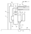
- FIG. 3 is a side view of the automatic filling device 100 according to the first embodiment.
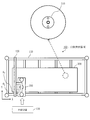
- FIG. 2 is a plan view of automatic filling apparatus 100 in the first embodiment.
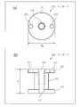
- FIG. 3 is a structural diagram of an insert 310 in the first embodiment.
- FIG. 3 is a structural diagram of panel 300 in the first embodiment.
- FIG. 3 is a structural diagram of panel 300 in the first embodiment.
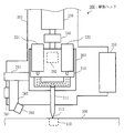
- FIG. 3 is a front view of the drive head 200 in the first embodiment.
- FIG. 3 is a side view of the drive head 200 in the first embodiment.
- FIG. 3 is a configuration diagram of a control device according to the first embodiment.
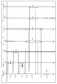
- FIG. 3 is a sequence diagram of the automatic filling method in the first embodiment.
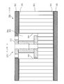
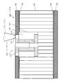
- FIG. 3 is a side cross-sectional view of panel 300 in the first embodiment.
- FIG. 3 is a side cross-sectional view of panel 300 in the first embodiment.
- FIG. 3 is a side cross-sectional view of panel 300 in the first embodiment.
- FIG. 5 shows a filling pattern in the first embodiment.
- FIG. 5 shows a filling pattern in the first embodiment.
- FIG. 5 shows a filling pattern in the first embodiment.
- FIG. 4 is a configuration diagram of a drive head 200 in a second embodiment. The hardware block diagram of the control apparatus 130 in embodiment.
- Embodiment 1 An embodiment in which an adhesive is automatically filled in the gap between the honeycomb sandwich panel and the insert embedded in the honeycomb sandwich panel will be described with reference to FIGS.
- FIG. 1 is a side view and FIG. 2 is a plan view.
- the X axis indicates the width direction
- the Y axis indicates the depth direction
- the Z axis indicates the height direction.
- the X-axis indicates the front-rear direction
- the Y-axis indicates the left-right direction
- the Z-axis indicates the up-down direction.
- O S indicates the origin of the work stage 110
- O P indicates the origin of the panel 300.
- the automatic filling apparatus 100 includes a work stage 110, a moving stage 120, a control device 130, and a drive head 200.
- the work stage 110 is a table on which the panel 300 is placed.
- the moving stage 120 is a frame to which the driving head 200 is attached.
- the moving stage 120 moves electrically in the front-rear direction. Further, the portion to which the drive head 200 is attached moves electrically in the left-right direction.
- the panel 300 is a plate provided with an embedding hole in which the insert 310 is embedded (see FIG. 2).
- the panel 300 has a small size of about 0.4 m ⁇ 0.6 m, and a large size of about 3 m ⁇ 5 m. Further, the number of embedded holes provided in the panel 300 is about 50 to 3000.
- the embedding hole is a depression.
- the embedded hole is provided by drilling using a drilling machine or the like. m means meter.
- the structure of the insert 310 will be described based on FIG. FIG. 3A is a plan view, and FIG. 3B is a side view.
- the insert 310 is a component for connecting an object to the panel 300.
- the insert 310 is a metal part.
- the connected object is any member or device.
- the insert 310 includes an upper flange 311, a lower flange 312, and a flange shaft 313.
- the upper flange 311 is a flange disposed on the upper side.
- the upper flange 311 has a disk shape.
- the upper flange 311 is provided with a screw hole 316 at the center and two holes with the screw hole 316 interposed therebetween. The two holes are positioned substantially symmetrically with the screw hole 316 interposed therebetween.
- One hole is referred to as an injection hole 314 and the other hole is referred to as a measurement hole 315.
- the injection hole 314 and the measurement hole 315 pass through the upper flange 311.
- the lower flange 312 is a flange disposed on the lower side.
- the lower flange 312 has a disk shape.
- a shaft hole 317 is provided at the center of the lower flange 312.
- the lower flange 312 does not have a hole corresponding to the injection hole 314 or the measurement hole 315.
- the flange shaft 313 is a shaft that connects the upper flange 311 and the lower flange 312.
- the flange shaft 313 has a cylindrical shape.
- the flange shaft 313 is provided with a screw hole 316 formed partway from the upper flange 311 and a shaft hole 317 that is connected to the screw hole 316 and penetrates to the lower flange 312.
- the specific size of the insert 310 is as follows.
- the diameter D M of the upper flange 311 and lower flange 312 are 10cm order of 1 cm. cm means centimeter.
- the height H of the insert 310 is about 1 cm to 5 cm. Note that the height H of the insert 310 is approximately the same as the depth of the embedded hole provided in the panel 300.
- the shape and size of the insert 310 shown in the embodiment is an example, and the shape and size of the insert 310 may be different from the shape and size shown in the embodiment.
- FIGS. 4 and 5 are side sectional views.
- the panel 300 is a honeycomb sandwich panel used for structures such as artificial satellites.
- the panel 300 includes a honeycomb core 301 and two skin materials 302, and the honeycomb core 301 is sandwiched between the skin materials 302.
- the honeycomb core 301 is composed of a plurality of connected polygonal columns (specifically hexagonal columns). Note that each of the plurality of polygonal columns has a cylindrical shape.
- the skin material 302 is bonded to the upper and lower portions of the honeycomb core 301 by the adhesive sheet 303.
- a specific skin material 302 is aluminum or CFRP (Carbon Fiber Reinforced Plastic).
- the adhesive sheet 303 is a sheet-like adhesive.
- each thickness T is about 1 cm to 5 cm.
- the depth D P of the embedding hole 304 is shallower than the thickness T of the panel 300.
- the depth D P of the embedding hole 304 is about half the thickness T of the panel 300.
- the surface of the upper flange 311 of the insert 310 and the surface of the upper skin material 302 have the same height.
- a gap 305 between the insert 310 and the honeycomb core 301 is filled with a filler.
- the gap 305 between the insert 310 and the honeycomb core 301 means a gap between the insert 310 embedded in the embedding hole 304 and the wall 306 adjacent to the insert 310 among the walls forming the honeycomb core 301.
- an adhesive that fixes the insert 310 to the honeycomb core 301 is filled as a filler.
- FIG. 6 is a front view
- FIG. 7 is a side view.
- portions related to the camera 250 and the laser displacement meter 260 are also illustrated, but in FIG. 7, portions related to the camera 250 and the laser displacement meter 260 are not shown.
- the driving head 200 is a device that fills a gap 305 between the insert 310 and the honeycomb core 301 with a filler.
- the driving head 200 includes a dispenser 210, a first tank 221, a second tank 222, an air cylinder 230, a load cell 240, a camera 250, and a laser displacement meter 260. Furthermore, the drive head 200 includes a moving block 201, a linear guide 202, and a base plate 203. Further, the drive head 200 includes an adjustment guide 261 and a base plate 262.
- the moving block 201 is attached to the rail 121 of the moving stage 120, and moves electrically up and down along the rail 121.
- the linear guide 202 is attached to the moving block 201 and moves up and down together with the moving block 201 when the moving block 201 moves up and down. Moreover, the linear guide 202 moves electrically up and down.
- the base plate 203 is attached to the linear guide 202, and moves up and down together with the linear guide 202 when the linear guide 202 moves up and down.
- the dispenser 210 is a device that discharges a filler.
- the dispenser 210 includes a nozzle 211.
- the nozzle 211 has a discharge port 212 through which a filler is discharged at the tip.
- the nozzle 211 is a static mixer that stirs and mixes a plurality of liquids.
- the 1st tank 221 is a container in which the 1st liquid which constitutes a filler is stored.
- the first liquid is supplied from the first tank 221 to the dispenser 210.
- the 2nd tank 222 is a container in which the 2nd liquid which constitutes a filler is stored.
- the second liquid is supplied from the second tank 222 to the dispenser 210.
- the filler is a mixed liquid in which the first liquid and the second liquid are mixed.
- the filler is a two-component mixed epoxy adhesive
- the first liquid is a high-viscosity main agent
- the second liquid is a low-viscosity curing agent.
- the two-component mixed epoxy adhesive is an adhesive in which a high-viscosity main agent and a low-viscosity curing agent are mixed.
- a filler having a medium viscosity or a high viscosity is selected so that the filler does not flow out of the minute hole.
- the air cylinder 230 is a device that moves the nozzle 211 of the dispenser 210 up and down by moving the base plate 203 up and down.
- the air cylinder 230 includes a first pipe 231, a second pipe 232, a regulator 233, and a piston 234.
- the regulator 233 is a device that moves the piston 234 up and down by air pressure by adjusting the air flowing through the first pipe 231 and the air flowing through the second pipe 232.
- the regulator 233 is an electropneumatic regulator.
- the load cell 240 is a sensor that measures the pressing force.
- the pressing force is a force by which the edge of the discharge port 212 of the nozzle 211 is pressed against the edge of the injection hole 314 of the insert 310.
- the load cell 240 measures the force by which the air cylinder 230 pushes down the base plate 203 as a pressing force.
- the camera 250 is a device that photographs the insert 310 located below the nozzle 211 of the dispenser 210.
- the adjustment guide 261 is attached to the moving block 201 and moves up and down together with the moving block 201 when the moving block 201 moves up and down. Further, the adjustment guide 261 moves electrically up, down, left and right.
- the base plate 262 is attached to the adjustment guide 261 and moves together with the adjustment guide 261 when the adjustment guide 261 moves.
- the laser displacement meter 260 is a device that emits laser light toward the lower side of the nozzle 211 of the dispenser 210 and measures the distance to the reflection point.
- the reflection point is a point where the laser beam is reflected.
- the laser displacement meter 260 emits a laser beam toward the measurement hole 315 of the insert 310 located below the nozzle 211, and reaches the liquid level of the filler injected from the injection hole 314 of the insert 310. Measure distance.
- the control device 130 is a computer that controls the moving stage 120 and the driving head 200.
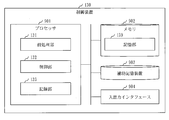
- the control device 130 includes hardware such as a processor 901, a memory 902, an auxiliary storage device 903, and an input / output interface 904. These hardwares are connected to each other via signal lines.
- the processor 901 is an IC (Integrated Circuit) that performs arithmetic processing, and controls other hardware. Specifically, the processor 901 is a CPU (Central Processing Unit).
- the memory 902 is a volatile storage device.
- the memory 902 is also called main memory or main memory.
- the memory 902 is a RAM (Random Access Memory).
- the auxiliary storage device 903 is a nonvolatile storage device. Specifically, the auxiliary storage device 903 is a ROM, HDD, or flash memory. ROM is an abbreviation for Read Only Memory, and HDD is an abbreviation for Hard Disk Drive.
- the input / output interface 904 is a port to which a cable connected to the moving stage 120 and a cable connected to the driving head 200 are connected.
- the control device 130 includes functional elements such as a preprocessing unit 131, a control unit 132, and a recording unit 133.
- the functional element is an element that constitutes a function of the control device 130.
- Functional elements are realized by software. Each functional element will be described later.
- the auxiliary storage device 903 stores a program that realizes functional elements.
- a program that implements functional elements is loaded into the memory 902 and executed by the processor 901.
- the auxiliary storage device 903 stores an OS (Operating System). At least a part of the OS is loaded into the memory 902 and executed by the processor 901. That is, the processor 901 executes a program that realizes functional elements while executing the OS.
- Data obtained by executing a program that implements functional elements is stored in a storage device such as the memory 902, the auxiliary storage device 903, a register in the processor 901, or a cache memory in the processor 901.
- the memory 902 functions as a storage unit 139 that stores data.
- another storage device may function as the storage unit 139 instead of the memory 902 or together with the memory 902.
- the control device 130 may include a plurality of processors that replace the processor 901.
- the plurality of processors share the execution of programs that implement functional elements.
- the program for realizing the functional elements can be stored in a computer-readable manner in a nonvolatile storage medium such as a magnetic disk, an optical disk, or a flash memory.
- a non-volatile storage medium is a tangible medium that is not temporary.
- the operation of the automatic filling apparatus 100 corresponds to an automatic filling method.
- the operation of the control device 130 corresponds to a filling control method.
- the procedure of the filling control method corresponds to the procedure of the filling control program. Processes executed by the preprocessing unit 131, the control unit 132, and the recording unit 133 are referred to as preprocessing, control processing, and recording processing, respectively.
- the pre-processing of the automatic filling method is a process of correcting position information indicating the coordinate value of the discharge port 212 of the nozzle 211.
- the position information is stored in the control device 130 in advance.
- the origin of coordinates in the initial position information is the origin O S of the work stage 110 (see FIG. 2).
- Preprocessing of the automatic filling method is performed in a state where the panel 300 is placed on the work stage 110 and the insert 310 is embedded in the embedding hole 304 of the panel 300.
- the insert 310 is embedded in the embedding hole 304 in a predetermined direction. Specifically, the insert 310 is embedded in the embedded hole 304 so that the injection hole 314 and the measurement hole 315 are aligned in the Y-axis direction.
- the orientation of the insert 310 needs to be unified to some extent. That is, it is necessary to embed the insert 310 in the embedding hole 304 so that the angle formed by the line connecting the injection hole 314 and the measurement hole 315 with respect to the Y axis becomes small. Specifically, the angle formed by the line connecting the injection hole 314 and the measurement hole 315 with respect to the Y axis needs to be within a range of minus 10 degrees to plus 10 degrees.
- the automatic filling apparatus 100 operates as follows.
- the storage unit 139 stores insert coordinate data in advance.
- the insert coordinate data includes the coordinate value of each insert 310.
- the origin of coordinates in the insert coordinate data the origin O P of the panel 300.
- the insert coordinate data is CAD data.
- CAD is an abbreviation for Computer Aided Design.
- the preprocessing unit 131 selects two coordinate values of the reference insert from the insert coordinate data.
- the reference insert is a reference insert 310.
- the reference insert is relatively far insert 310 from the origin O P relatively close insert 310 and the origin O P.
- the preprocessing unit 131 calculates a movement amount based on the coordinate value of the reference insert.
- the preprocessing unit 131 outputs a movement instruction to the movement stage 120 and the movement block 201 based on the calculated movement amount. In response to the movement instruction, the movement stage 120 and the movement block 201 move the nozzle 211 above the reference insert.
- the preprocessing unit 131 outputs a shooting instruction to the camera 250. In response to the shooting instruction, the camera 250 captures the reference insert to obtain an image. Then, the camera 250 outputs the obtained image to the preprocessing unit 131.
- the preprocessing unit 131 receives the image, and calculates the positional deviation amount and the angular deviation amount of the reference insert in the image.
- the positional deviation amount of the reference insert is the magnitude of deviation between the coordinate value of the reference insert in the insert coordinate data and the coordinate value of the reference insert in the image.
- the angle deviation amount of the reference insert is a line obtained by connecting the coordinate values of the two reference inserts of the two reference inserts in the insert coordinate data to the line obtained by connecting the coordinate values of the two reference inserts of the two reference inserts in the image. It is the angle formed with respect to it.
- the preprocessing unit 131 converts the coordinate value of the reference insert in the insert coordinate data into a coordinate value when the coordinate axis in the insert coordinate data is rotated by the amount of angular deviation. Thereafter, the preprocessing unit 131 adds the amount of displacement to the coordinate value of the reference insert in the insert coordinate data.
- the automatic filling method is a method of filling the gap 305 between the insert 310 and the honeycomb core 301 with a filler.
- the automatic filling method is performed after the above pretreatment.
- the processing from step S101 to step S107 is executed for each insert 310.
- Step S ⁇ b> 101 is a step of moving the nozzle 211 above the insert 310.
- Step S101 will be described below.
- the control unit 132 selects the coordinate value of the insert 310 from the insert coordinate data.
- the control unit 132 calculates a movement amount based on the position information and the coordinate value of the insert 310.
- the control unit 132 outputs a movement instruction to the movement stage 120 based on the calculated movement amount.
- the control unit 132 updates the position information based on the calculated movement amount.
- the moving stage 120 moves the nozzle 211 above the insert 310.
- the air cylinder 230 pulls up the dispenser 210 via the base plate 203 with a force that opposes the weight of the parts including the dispenser 210. Thereby, the parts including the dispenser 210 do not descend due to their own weight.
- the components including the dispenser 210 are the dispenser 210, the base plate 203, the first tank 221, the second tank 222, the base plate 203, and the linear guide 202.
- Step S102 is a step of measuring the deviation amount of the injection hole 314 in the insert 310 and the deviation amount of the measurement hole 315 in the insert 310.
- the shift amount of the injection hole 314 is the amount of shift between the reference position for the injection hole 314 and the position of the injection hole 314.
- the amount of deviation of the measurement hole 315 is the magnitude of deviation of the XY coordinates between the reference position for the measurement hole 315 and the position of the measurement hole 315.
- Step S102 will be described below.
- the control unit 132 outputs a shooting instruction to the camera 250.
- the camera 250 receives the shooting instruction and takes an image of the insert 310 to obtain an image.
- the camera 250 detects the injection hole 314 of the insert 310 from the image, and calculates the position of the injection hole 314 of the insert 310 in the image.
- the camera 250 detects the measurement hole 315 of the insert 310 from the image, and calculates the position of the measurement hole 315 of the insert 310 in the image.
- the camera 250 outputs a detection result indicating the position of the injection hole 314 of the insert 310 in the image and the position of the measurement hole 315 of the insert 310 in the image to the control unit 132.
- the control unit 132 receives the detection result.
- the control part 132 calculates the deviation
- the control part 132 calculates the deviation
- Step S103 is a step of correcting the position of the nozzle 211 and the position of the laser displacement meter 260. Step S103 will be described below.
- the control unit 132 outputs a movement instruction to the moving stage 120 based on the amount of deviation of the injection hole 314 in the insert 310. Further, the control unit 132 updates the position information based on the shift amount of the injection hole 314 of the insert 310.
- the moving stage 120 moves the discharge port 212 of the nozzle 211 above the injection hole 314 of the insert 310.
- the control unit 132 outputs a movement instruction to the adjustment guide 261 based on the shift amount of the measurement hole 315 in the insert 310.
- the adjustment guide 261 receives the movement instruction and moves the laser displacement meter 260. Specifically, the adjustment guide 261 moves the laser displacement meter 260 to a position where the laser light is emitted toward the measurement hole 315.
- Step S104 is a step of pressing the edge of the discharge port 212 of the nozzle 211 against the edge of the injection hole 314 of the insert 310. Step S104 will be described below.
- the control unit 132 outputs a lowering instruction to the moving block 201.
- the movement block 201 receives the lowering instruction and moves the nozzle 211 downward. Specifically, the moving block 201 outputs a lowering instruction until the edge of the discharge port 212 of the nozzle 211 comes into contact with the edge of the injection hole 314 of the insert 310.
- the control unit 132 outputs a measurement instruction to the load cell 240. In response to the measurement instruction, the load cell 240 starts measuring the pressing force.
- the pressing force is a force applied from the air cylinder 230 to the nozzle 211.
- the load cell 240 repeats the measurement of the pressing force until the measurement of the pressing force is stopped, and outputs the measurement result to the control unit 132 every time the pressing force is measured.
- This measurement result shows the measured pressing force.
- the control unit 132 outputs a pressing instruction to the air cylinder 230 based on the pressing force indicated by the measurement result.
- the air cylinder 230 pushes down the dispenser 210 via the base plate 203. Thereby, the edge of the discharge port 212 of the nozzle 211 is pressed against the edge of the injection hole 314 of the insert 310 to such an extent that the pressing force falls within the pressing force range.
- the insert 310 is embedded in the embedded hole 304 of the panel 300.
- the edge of the discharge port 212 of the nozzle 211 is pressed against the edge of the injection hole 314 of the insert 310.
- Step S105 is a step of filling the gap 305 between the insert 310 and the honeycomb core 301 with a filler. Step S105 will be described below.
- the control unit 132 outputs a measurement instruction to the laser displacement meter 260.
- the laser displacement meter 260 starts measuring the liquid level distance.
- the liquid level distance is a distance from the injection hole 314 of the insert 310 to the liquid level of the filler injected.
- the laser displacement meter 260 emits laser light toward the measurement hole 315 of the insert 310 and receives the laser light reflected on the liquid surface of the filler.
- the laser displacement meter 260 then calculates the liquid level distance based on the time from when the laser beam is emitted until it is received. After the measurement of the liquid level distance is started, the laser displacement meter 260 repeats the measurement of the liquid level distance until the measurement of the liquid level distance is stopped. Output measurement results. This measurement result indicates the measured liquid level distance.
- the control unit 132 outputs a filling instruction to the dispenser 210. In response to the filling instruction, the dispenser 210 starts discharging the filler. The dispenser 210 discharges the filler from the discharge port 212 of the nozzle 211 until the discharge of the filler is stopped after the discharge of the filler is started. The filling speed is constant.
- the dispenser 210 injects the main agent and the curing agent into the nozzle 211. Then, the nozzle 211 stirs and mixes the main agent and the curing agent, and discharges the adhesive mixed with the main agent and the curing agent from the discharge port 212. The discharged adhesive is injected from the injection hole 314 of the insert 310 and filled in the gap 305 between the insert 310 and the honeycomb core 301.
- the dispenser 210 replenishes the main agent from the first tank 221 when the main agent is insufficient, and replenishes the hardener from the second tank 222 when the hardener is insufficient.
- the control unit 132 calculates the height of the liquid level of the filler based on the liquid level distance indicated by the measurement result. And the control part 132 determines whether the height of the liquid level of the filler reached the target height.
- the target height is a predetermined height. Specifically, the target height is the same height as the surface of the upper flange 311 of the insert 310.
- the control unit 132 outputs a filling stop instruction to the dispenser 210. In response to the filling stop instruction, the dispenser 210 stops discharging the filler.
- step S105 the state of the panel 300, the insert 310, and the nozzle 211 after step S105 will be described.
- Fillers are represented by dot shading.
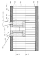
- a gap 305 between the insert 310 and the honeycomb core 301 is filled with a filler discharged from the discharge port 212 of the nozzle 211 and injected from the injection hole 314 of the insert 310.
- the liquid level of the filler reaches the surface of the insert 310.
- the liquid level of the filler is detected by the laser beam 263 from the laser displacement meter 260.
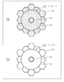
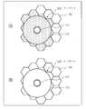
- FIGS. 12 to 14A are plan views of the periphery of the insert 310 in FIG. 11A
- FIGS. 12 to 14B are plan views of the periphery of the insert 310 in FIG. FIG.
- the filler is filled around the flange shaft 313 of the insert 310 regardless of the positional relationship between the insert 310 and the honeycomb core 301.
- a filler is filled in a portion of the honeycomb core 301 adjacent to the insert 310.
- a portion of the honeycomb core 301 that is not adjacent to the insert 310 is not filled with a filler.
- the filler is not filled below the insert 310. That is, the filler is not filled to the lower part of the honeycomb core 301, and the panel 300 after the filler is filled does not become excessively heavy. This is because a flow stop treatment is applied. Specifically, a flow stopping treatment using a GFRP plate is performed.
- GFRP is an abbreviation for Glass Fiber Reinforced Plastic.
- Step S ⁇ b> 106 is a step of separating the edge of the discharge port 212 of the nozzle 211 from the edge of the injection hole 314 of the insert 310. Step S106 will be described below.
- the control unit 132 outputs a pressing stop instruction to the air cylinder 230.
- the air cylinder 230 pulls up the dispenser 210 via the base plate 203 with a force that opposes the weight of the parts including the dispenser 210.
- the control unit 132 outputs a measurement stop instruction to the load cell 240.
- the load cell 240 receives the measurement stop instruction and stops the measurement of the pressing force.
- the control unit 132 outputs an ascending instruction to the moving block 201.
- the moving block 201 receives the ascending instruction and moves the nozzle 211 upward. Specifically, the moving block 201 moves the edge of the discharge port 212 of the nozzle 211 to the edge of the insert 310 until the interval between the edge of the discharge port 212 of the nozzle 211 and the edge of the injection hole 314 of the insert 310 becomes the first interval. Separate from the edge of the injection hole 314.
- Step S107 is a process of recording a work history. Step S107 will be described below.
- the storage unit 139 stores a work history file in advance.
- the work history file includes a work history for each work performed.
- the recording unit 133 records the work history of the work performed in the processing from step S101 to step S106 in the work history file.
- the recording unit 133 records the insert identifier, the filling date and time, and the like in the work history file.
- the insert identifier is an identifier that identifies the insert 310.
- the filling date and time is the date and time when the filler is injected from the injection hole 314 of the insert 310 and filled in the gap 305 between the insert 310 and the honeycomb core 301.
- the filling date and time are the date and time when the filling instruction is output and the date and time when the filling stop instruction is output.
- Embodiment 1 it is possible to automatically fill the filler. Specifically, metal parts for connecting members or equipment are bonded with an adhesive using an automatic filling device to a honeycomb sandwich panel used in a structure such as an artificial satellite, a flying body or an in-vehicle shelter. be able to. This makes it possible to simplify the work of filling the adhesive and the work of leaving a work record.
- the honeycomb core of the honeycomb sandwich panel is a combination of polygons in cross section. Therefore, there is a difference in the amount of adhesive to be filled according to the position of the insert and the shape of the honeycomb core, and the filling amount cannot be uniquely determined.
- the drive head 200 includes a main agent dispenser and a tank, and further includes a curing agent dispenser and a tank.
- the backflow occurs because the main agent and the curing agent are pushed back by the pressure generated when the main agent and the curing agent are discharged and mixed in the static mixer (nozzle 211).
- the dispenser used for the curing agent has a smaller discharging force and tends to cause a backflow. Therefore, it is preferable to narrow the flow path of the curing agent. Thereby, since the discharge pressure of the curing agent increases, it becomes possible to prevent backflow.
- the flow path diameter may be designed so that the force necessary for discharging the curing agent is within the range of the performance of the dispenser.
- the pressing force is measured by the load cell, and the nozzle is pressed against the insert by the air cylinder with an appropriate pressing force. That is, even if the amount of the filler stored in the tank changes, the nozzle can be pressed against the insert with an appropriate pressing force. Therefore, the adhesive does not leak from the insert. Moreover, even if the nozzle is pressed against the insert, the honeycomb sandwich panel is not damaged.
- Embodiment 2 With respect to a mode in which a lifting force that opposes the weight of the component including the dispenser 210 is generated using a spring, a point different from the first embodiment will be mainly described with reference to FIG.
- the air cylinder 230 is illustrated in a simplified manner. Specifically, the first pipe 231, the second pipe 232, the regulator 233 and the piston 234 are omitted. Further, the adjustment guide 261 and the base plate 262 for moving the laser displacement meter 260 are not shown.
- the drive head 200 includes a fixed block 204 and two springs 205 in addition to the elements described in the first embodiment.
- the fixed block 204 is fixed to the moving block 201.
- a dispenser 210 is attached to the fixed block 204.
- the base plate 203 is disposed below the fixed block 204.
- a first tank 221 and a second tank 222 are attached to the upper surface of the base plate 203.
- the first tank 221 is disposed at the left end of the base plate 203, and the second tank 222 is disposed at the right end of the base plate 203.
- a dispenser 210 is attached to the lower surface of the base plate 203.
- the dispenser 210 is disposed in the center of the base plate 203.
- the two springs 205 are provided between the fixed block 204 and the base plate 203.
- the two springs 205 are arranged on the left and right with the dispenser 210 interposed therebetween.
- the two springs 205 pull up the base plate 203 with a pulling force that opposes the weight of the parts including the dispenser 210.
- the parts including the dispenser 210 are the dispenser 210, the base plate 203, the first tank 221, and the second tank 222.
- the part that generates the lifting force against the weight of the part including the dispenser 210 is not the dispenser 210 but two springs 205. In other respects, the automatic filling method is the same as that of the first embodiment.
- the function of the control device 130 may be realized by hardware.
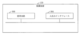
- FIG. 16 shows a configuration when the function of the control device 130 is realized by hardware.
- the control device 130 includes a processing circuit 990.
- the processing circuit 990 is also called a processing circuit.
- the processing circuit 990 is a dedicated electronic circuit that implements functional elements such as the preprocessing unit 131, the control unit 132, the recording unit 133, and the storage unit 139.
- the processing circuit 990 is a single circuit, a composite circuit, a programmed processor, a parallel programmed processor, a logic IC, a GA, an ASIC, an FPGA, or a combination thereof.
- GA is an abbreviation for Gate Array
- ASIC is an abbreviation for Application Specific Integrated Circuit
- FPGA is an abbreviation for Field Programmable Gate Array.
- the control device 130 may include a plurality of processing circuits that replace the processing circuit 990.
- the plurality of processing circuits share the role of functional elements.
- control device 130 may be realized by a combination of software and hardware. That is, some functional elements may be realized by software, and the remaining functional elements may be realized by hardware.
- the functional element may be realized by firmware.
- the embodiment is an example of a preferred embodiment and is not intended to limit the technical scope of the present invention.
- the embodiment may be implemented partially or in combination with other embodiments.
- the procedure described using the arrangement of component elements and the sequence diagram may be changed as appropriate.
- 100 automatic filling device 110 work stage, 120 moving stage, 121 rail, 130 control device, 131 preprocessing unit, 132 control unit, 133 recording unit, 139 storage unit, 200 driving head, 201 moving block, 202 linear guide, 203 Base plate, 204 fixed block, 205 spring, 210 dispenser, 211 nozzle, 212 outlet, 221 first tank, 222 second tank, 230 air cylinder, 231 first pipe, 232 second pipe, 233 regulator, 234 piston, 240 Load cell, 250 camera, 260 laser displacement meter, 261 adjustment guide, 262 base plate, 263 laser light, 300 panel, 301 honeycomb core, 302 skin material, 30 Adhesive sheet, 304 embedded hole, 305 gap, 306 wall, 310 insert, 311 upper flange, 312 lower flange, 313 flange shaft, 314 injection hole, 315 measurement hole, 316 screw hole, 317 shaft hole, 901 processor, 902 memory, 903 Auxiliary storage device, 904 input / output interface,
Landscapes
- Engineering & Computer Science (AREA)
- Mechanical Engineering (AREA)
- Chemical & Material Sciences (AREA)
- General Engineering & Computer Science (AREA)
- Composite Materials (AREA)
- Organic Chemistry (AREA)
- Coating Apparatus (AREA)
Abstract
Selon la présente invention, dans un état dans lequel un insert (310) est intégré dans un trou d'incorporation d'un panneau (300) et une buse (211) d'un distributeur (210) est positionnée au-dessus d'un trou d'injection de l'insert, un cylindre à air (230) presse un bord d'une ouverture d'évacuation (212) de la buse contre un bord du trou d'injection de l'insert. Ensuite, le distributeur fait sortir un adhésif par l'ouverture d'évacuation de la buse. L'adhésif est inséré à partir du trou d'injection de l'insert et remplit l'espace entre l'insert et le panneau. Ainsi, l'insert est fixé au panneau.
Priority Applications (4)
| Application Number | Priority Date | Filing Date | Title |
|---|---|---|---|
| EP16922257.7A EP3384996A4 (fr) | 2016-11-25 | 2016-11-25 | Dispositif de remplissage automatique |
| JP2018506356A JP6320667B1 (ja) | 2016-11-25 | 2016-11-25 | 自動充填装置 |
| PCT/JP2016/085023 WO2018096660A1 (fr) | 2016-11-25 | 2016-11-25 | Dispositif de remplissage automatique |
| US15/775,861 US10940644B2 (en) | 2016-11-25 | 2016-11-25 | Automatic charging apparatus |
Applications Claiming Priority (1)
| Application Number | Priority Date | Filing Date | Title |
|---|---|---|---|
| PCT/JP2016/085023 WO2018096660A1 (fr) | 2016-11-25 | 2016-11-25 | Dispositif de remplissage automatique |
Publications (1)
| Publication Number | Publication Date |
|---|---|
| WO2018096660A1 true WO2018096660A1 (fr) | 2018-05-31 |
Family
ID=62107307
Family Applications (1)
| Application Number | Title | Priority Date | Filing Date |
|---|---|---|---|
| PCT/JP2016/085023 Ceased WO2018096660A1 (fr) | 2016-11-25 | 2016-11-25 | Dispositif de remplissage automatique |
Country Status (4)
| Country | Link |
|---|---|
| US (1) | US10940644B2 (fr) |
| EP (1) | EP3384996A4 (fr) |
| JP (1) | JP6320667B1 (fr) |
| WO (1) | WO2018096660A1 (fr) |
Cited By (1)
| Publication number | Priority date | Publication date | Assignee | Title |
|---|---|---|---|---|
| CN110773385A (zh) * | 2019-12-02 | 2020-02-11 | 安徽福瑞尔铝业科技有限公司 | 一种铝蜂窝板的蜂窝芯封边设备 |
Families Citing this family (3)
| Publication number | Priority date | Publication date | Assignee | Title |
|---|---|---|---|---|
| RU201803U1 (ru) * | 2020-07-31 | 2021-01-13 | Акционерное общество «Информационные спутниковые системы» имени академика М.Ф. Решетнёва» | Опорный узел сотовой панели |
| CN112659422B (zh) * | 2020-12-16 | 2022-07-15 | 广东晟沛建设有限公司 | 一种市政下水道盖注塑孔废料去除装置 |
| CN112705421A (zh) * | 2020-12-25 | 2021-04-27 | 深圳市轴心自控技术有限公司 | 一种用于抓边点胶功能的处理系统 |
Citations (7)
| Publication number | Priority date | Publication date | Assignee | Title |
|---|---|---|---|---|
| JPS59144777U (ja) * | 1983-03-16 | 1984-09-27 | 三菱電機株式会社 | ハニカムパネル接地用インサ−ト |
| JPH02109893A (ja) * | 1988-10-14 | 1990-04-23 | Kao Corp | 自動充填方法及び装置 |
| JPH04244695A (ja) * | 1991-01-30 | 1992-09-01 | Sekisui Chem Co Ltd | シール材充填装置 |
| JPH0531427A (ja) * | 1991-07-29 | 1993-02-09 | Sekisui Chem Co Ltd | 二液混合型接着剤吐出装置 |
| JPH1043655A (ja) * | 1996-08-02 | 1998-02-17 | Anest Iwata Corp | 高粘度材料カートリッジによるディスペンサと 多段シリンダ |
| JP2001140362A (ja) | 1999-11-17 | 2001-05-22 | Mitsubishi Electric Corp | インサート充填方法 |
| JP2001271424A (ja) * | 2000-03-23 | 2001-10-05 | Takahashi Hiroshi | 接合具及びそれを用いた構造部材の接合構造並びに構造部材の接合方法 |
Family Cites Families (8)
| Publication number | Priority date | Publication date | Assignee | Title |
|---|---|---|---|---|
| US4661368A (en) * | 1985-09-18 | 1987-04-28 | Universal Instruments Corporation | Surface locating and dispensed dosage sensing method and apparatus |
| JPH02175238A (ja) * | 1988-12-28 | 1990-07-06 | Jamco Corp | ハニカムパネルの連続成形方法 |
| WO2002053297A1 (fr) * | 2000-12-27 | 2002-07-11 | Toray Industries, Inc. | Embout buccal et dispositif, et procede d'application d'un fluide de revetement |
| US20090236025A1 (en) * | 2008-03-24 | 2009-09-24 | Nordson Corporation | Apparatus and methods for producing foamed materials |
| FR2990890B1 (fr) * | 2012-05-28 | 2015-01-30 | Latecis | Procede de pose automatique de moyens de fixation dans un panneau en nid d'abeille, ensemble de modules et appareil de pose automatique pour la mise en oeuvre du procede. |
| WO2014060027A1 (fr) * | 2012-10-17 | 2014-04-24 | Ruag Schweiz Ag | Procédé et système d'insertion d'un élément d'insertion dans un produit formant panneau, produit formant panneau fabriqué au moyen de ces derniers et procédé et système permettant de mettre œuvre un essai de traction sur l'élément d'insertion inséré |
| US9981446B2 (en) * | 2013-09-03 | 2018-05-29 | The Boeing Company | Structural inserts for honeycomb structures |
| US10228684B2 (en) * | 2015-11-23 | 2019-03-12 | The Boeing Company | Automated fastener insert installation system for composite panels |
-
2016
- 2016-11-25 US US15/775,861 patent/US10940644B2/en active Active
- 2016-11-25 WO PCT/JP2016/085023 patent/WO2018096660A1/fr not_active Ceased
- 2016-11-25 EP EP16922257.7A patent/EP3384996A4/fr not_active Withdrawn
- 2016-11-25 JP JP2018506356A patent/JP6320667B1/ja active Active
Patent Citations (7)
| Publication number | Priority date | Publication date | Assignee | Title |
|---|---|---|---|---|
| JPS59144777U (ja) * | 1983-03-16 | 1984-09-27 | 三菱電機株式会社 | ハニカムパネル接地用インサ−ト |
| JPH02109893A (ja) * | 1988-10-14 | 1990-04-23 | Kao Corp | 自動充填方法及び装置 |
| JPH04244695A (ja) * | 1991-01-30 | 1992-09-01 | Sekisui Chem Co Ltd | シール材充填装置 |
| JPH0531427A (ja) * | 1991-07-29 | 1993-02-09 | Sekisui Chem Co Ltd | 二液混合型接着剤吐出装置 |
| JPH1043655A (ja) * | 1996-08-02 | 1998-02-17 | Anest Iwata Corp | 高粘度材料カートリッジによるディスペンサと 多段シリンダ |
| JP2001140362A (ja) | 1999-11-17 | 2001-05-22 | Mitsubishi Electric Corp | インサート充填方法 |
| JP2001271424A (ja) * | 2000-03-23 | 2001-10-05 | Takahashi Hiroshi | 接合具及びそれを用いた構造部材の接合構造並びに構造部材の接合方法 |
Non-Patent Citations (1)
| Title |
|---|
| See also references of EP3384996A4 |
Cited By (2)
| Publication number | Priority date | Publication date | Assignee | Title |
|---|---|---|---|---|
| CN110773385A (zh) * | 2019-12-02 | 2020-02-11 | 安徽福瑞尔铝业科技有限公司 | 一种铝蜂窝板的蜂窝芯封边设备 |
| CN110773385B (zh) * | 2019-12-02 | 2020-08-28 | 安徽福瑞尔铝业科技有限公司 | 一种铝蜂窝板的蜂窝芯封边设备 |
Also Published As
| Publication number | Publication date |
|---|---|
| JPWO2018096660A1 (ja) | 2018-11-29 |
| EP3384996A1 (fr) | 2018-10-10 |
| JP6320667B1 (ja) | 2018-05-09 |
| US20190283336A1 (en) | 2019-09-19 |
| US10940644B2 (en) | 2021-03-09 |
| EP3384996A4 (fr) | 2019-04-17 |
Similar Documents
| Publication | Publication Date | Title |
|---|---|---|
| JP6320667B1 (ja) | 自動充填装置 | |
| US11964424B2 (en) | Apparatus for making a stereolithographic object, methods for making a stereolithographic object, a method for locating the position of debris, and a method for monitoring consumption of a material for making a stereolithographic object | |
| US11097476B2 (en) | Position detection techniques for additive fabrication and related systems and methods | |
| US11318673B2 (en) | Film tensioning techniques for additive fabrication and related systems and methods | |
| US20220363048A1 (en) | Techniques for additive fabrication process optimization and related systems and methods | |
| US5932012A (en) | Paste applicator having positioning means | |
| US20090154775A1 (en) | Fitting doublers using gap mapping | |
| CN115720547A (zh) | 用于增材制造复合结构的方法 | |
| JP2809588B2 (ja) | ペースト塗布機 | |
| US20200238627A1 (en) | System for additively manufacturing composite structure | |
| US11604410B2 (en) | Apparatus and method for making a stereolithographic object | |
| US11338937B2 (en) | Installation comprising an articulated arm and a machine tool, and corresponding machining method | |
| KR101633577B1 (ko) | 부재 접합 시스템 | |
| KR101740146B1 (ko) | 펌프 위치 피드백 방식 디스펜서 및 디스펜싱 방법 | |
| CN1895875A (zh) | 一种用于光固化快速成型工艺的精度校正方法 | |
| JP2011235237A (ja) | 塗布剤塗布方法および塗布剤塗布装置 | |
| Lohuis et al. | Mechanical testing of threaded inserts for additively manufactured sandwich panels with Gyroid core structures | |
| CN115256938B (zh) | 理想辐射参数测试方法、系统、3d打印方法及打印设备 | |
| US20260084378A1 (en) | Printing device, printing system, and method for controlling printing device | |
| KR101831301B1 (ko) | 입체형상의 기판을 레진 접합하는 라미네이션 접합 장치 및 방법, 그것을 이용하여 제조된 입체형상의 기판 | |
| JP7450219B2 (ja) | 施工方法、製作方法、情報処理装置 | |
| US20180356215A1 (en) | Composite parts that facilitate ultrasonic imaging of layer boundaries | |
| CN209775556U (zh) | 3d打印设备 | |
| JP7456907B2 (ja) | アンカーボルト検査システム及び測定装置 | |
| CN109940879B (zh) | 一种新型可见光固化3d打印机的控制系统及方法 |
Legal Events
| Date | Code | Title | Description |
|---|---|---|---|
| ENP | Entry into the national phase |
Ref document number: 2018506356 Country of ref document: JP Kind code of ref document: A |
|
| WWE | Wipo information: entry into national phase |
Ref document number: 2016922257 Country of ref document: EP |
|
| ENP | Entry into the national phase |
Ref document number: 2016922257 Country of ref document: EP Effective date: 20180705 |
|
| NENP | Non-entry into the national phase |
Ref country code: DE |