WO2018155502A1 - Malaxeur multi-vis et méthode de fabrication de nano-composite utilisant ledit malaxeur multi-vis, et segment en forme de disque utilisé pour ledit malaxeur et ladite méthode - Google Patents
Malaxeur multi-vis et méthode de fabrication de nano-composite utilisant ledit malaxeur multi-vis, et segment en forme de disque utilisé pour ledit malaxeur et ladite méthode Download PDFInfo
- Publication number
- WO2018155502A1 WO2018155502A1 PCT/JP2018/006270 JP2018006270W WO2018155502A1 WO 2018155502 A1 WO2018155502 A1 WO 2018155502A1 JP 2018006270 W JP2018006270 W JP 2018006270W WO 2018155502 A1 WO2018155502 A1 WO 2018155502A1
- Authority
- WO
- WIPO (PCT)
- Prior art keywords
- kneading
- disk
- kneader
- screw
- barrel
- Prior art date
- Legal status (The legal status is an assumption and is not a legal conclusion. Google has not performed a legal analysis and makes no representation as to the accuracy of the status listed.)
- Ceased
Links
Images





















Classifications
-
- B—PERFORMING OPERATIONS; TRANSPORTING
- B29—WORKING OF PLASTICS; WORKING OF SUBSTANCES IN A PLASTIC STATE IN GENERAL
- B29B—PREPARATION OR PRETREATMENT OF THE MATERIAL TO BE SHAPED; MAKING GRANULES OR PREFORMS; RECOVERY OF PLASTICS OR OTHER CONSTITUENTS OF WASTE MATERIAL CONTAINING PLASTICS
- B29B7/00—Mixing; Kneading
- B29B7/30—Mixing; Kneading continuous, with mechanical mixing or kneading devices
- B29B7/34—Mixing; Kneading continuous, with mechanical mixing or kneading devices with movable mixing or kneading devices
- B29B7/38—Mixing; Kneading continuous, with mechanical mixing or kneading devices with movable mixing or kneading devices rotary
- B29B7/46—Mixing; Kneading continuous, with mechanical mixing or kneading devices with movable mixing or kneading devices rotary with more than one shaft
- B29B7/48—Mixing; Kneading continuous, with mechanical mixing or kneading devices with movable mixing or kneading devices rotary with more than one shaft with intermeshing devices, e.g. screws
- B29B7/482—Mixing; Kneading continuous, with mechanical mixing or kneading devices with movable mixing or kneading devices rotary with more than one shaft with intermeshing devices, e.g. screws provided with screw parts in addition to other mixing parts, e.g. paddles, gears, discs
-
- B—PERFORMING OPERATIONS; TRANSPORTING
- B29—WORKING OF PLASTICS; WORKING OF SUBSTANCES IN A PLASTIC STATE IN GENERAL
- B29B—PREPARATION OR PRETREATMENT OF THE MATERIAL TO BE SHAPED; MAKING GRANULES OR PREFORMS; RECOVERY OF PLASTICS OR OTHER CONSTITUENTS OF WASTE MATERIAL CONTAINING PLASTICS
- B29B7/00—Mixing; Kneading
- B29B7/30—Mixing; Kneading continuous, with mechanical mixing or kneading devices
- B29B7/34—Mixing; Kneading continuous, with mechanical mixing or kneading devices with movable mixing or kneading devices
- B29B7/38—Mixing; Kneading continuous, with mechanical mixing or kneading devices with movable mixing or kneading devices rotary
- B29B7/46—Mixing; Kneading continuous, with mechanical mixing or kneading devices with movable mixing or kneading devices rotary with more than one shaft
- B29B7/48—Mixing; Kneading continuous, with mechanical mixing or kneading devices with movable mixing or kneading devices rotary with more than one shaft with intermeshing devices, e.g. screws
- B29B7/482—Mixing; Kneading continuous, with mechanical mixing or kneading devices with movable mixing or kneading devices rotary with more than one shaft with intermeshing devices, e.g. screws provided with screw parts in addition to other mixing parts, e.g. paddles, gears, discs
- B29B7/483—Mixing; Kneading continuous, with mechanical mixing or kneading devices with movable mixing or kneading devices rotary with more than one shaft with intermeshing devices, e.g. screws provided with screw parts in addition to other mixing parts, e.g. paddles, gears, discs the other mixing parts being discs perpendicular to the screw axis
-
- B—PERFORMING OPERATIONS; TRANSPORTING
- B29—WORKING OF PLASTICS; WORKING OF SUBSTANCES IN A PLASTIC STATE IN GENERAL
- B29B—PREPARATION OR PRETREATMENT OF THE MATERIAL TO BE SHAPED; MAKING GRANULES OR PREFORMS; RECOVERY OF PLASTICS OR OTHER CONSTITUENTS OF WASTE MATERIAL CONTAINING PLASTICS
- B29B7/00—Mixing; Kneading
- B29B7/30—Mixing; Kneading continuous, with mechanical mixing or kneading devices
- B29B7/34—Mixing; Kneading continuous, with mechanical mixing or kneading devices with movable mixing or kneading devices
- B29B7/38—Mixing; Kneading continuous, with mechanical mixing or kneading devices with movable mixing or kneading devices rotary
- B29B7/46—Mixing; Kneading continuous, with mechanical mixing or kneading devices with movable mixing or kneading devices rotary with more than one shaft
- B29B7/48—Mixing; Kneading continuous, with mechanical mixing or kneading devices with movable mixing or kneading devices rotary with more than one shaft with intermeshing devices, e.g. screws
- B29B7/488—Parts, e.g. casings, sealings; Accessories, e.g. flow controlling or throttling devices
-
- B—PERFORMING OPERATIONS; TRANSPORTING
- B29—WORKING OF PLASTICS; WORKING OF SUBSTANCES IN A PLASTIC STATE IN GENERAL
- B29B—PREPARATION OR PRETREATMENT OF THE MATERIAL TO BE SHAPED; MAKING GRANULES OR PREFORMS; RECOVERY OF PLASTICS OR OTHER CONSTITUENTS OF WASTE MATERIAL CONTAINING PLASTICS
- B29B7/00—Mixing; Kneading
- B29B7/30—Mixing; Kneading continuous, with mechanical mixing or kneading devices
- B29B7/34—Mixing; Kneading continuous, with mechanical mixing or kneading devices with movable mixing or kneading devices
- B29B7/38—Mixing; Kneading continuous, with mechanical mixing or kneading devices with movable mixing or kneading devices rotary
- B29B7/46—Mixing; Kneading continuous, with mechanical mixing or kneading devices with movable mixing or kneading devices rotary with more than one shaft
- B29B7/48—Mixing; Kneading continuous, with mechanical mixing or kneading devices with movable mixing or kneading devices rotary with more than one shaft with intermeshing devices, e.g. screws
- B29B7/488—Parts, e.g. casings, sealings; Accessories, e.g. flow controlling or throttling devices
- B29B7/489—Screws
-
- B—PERFORMING OPERATIONS; TRANSPORTING
- B29—WORKING OF PLASTICS; WORKING OF SUBSTANCES IN A PLASTIC STATE IN GENERAL
- B29B—PREPARATION OR PRETREATMENT OF THE MATERIAL TO BE SHAPED; MAKING GRANULES OR PREFORMS; RECOVERY OF PLASTICS OR OTHER CONSTITUENTS OF WASTE MATERIAL CONTAINING PLASTICS
- B29B7/00—Mixing; Kneading
- B29B7/30—Mixing; Kneading continuous, with mechanical mixing or kneading devices
- B29B7/58—Component parts, details or accessories; Auxiliary operations
- B29B7/72—Measuring, controlling or regulating
- B29B7/726—Measuring properties of mixture, e.g. temperature or density
-
- B—PERFORMING OPERATIONS; TRANSPORTING
- B29—WORKING OF PLASTICS; WORKING OF SUBSTANCES IN A PLASTIC STATE IN GENERAL
- B29B—PREPARATION OR PRETREATMENT OF THE MATERIAL TO BE SHAPED; MAKING GRANULES OR PREFORMS; RECOVERY OF PLASTICS OR OTHER CONSTITUENTS OF WASTE MATERIAL CONTAINING PLASTICS
- B29B7/00—Mixing; Kneading
- B29B7/80—Component parts, details or accessories; Auxiliary operations
- B29B7/84—Venting or degassing ; Removing liquids, e.g. by evaporating components
- B29B7/845—Venting, degassing or removing evaporated components in devices with rotary stirrers
-
- B—PERFORMING OPERATIONS; TRANSPORTING
- B29—WORKING OF PLASTICS; WORKING OF SUBSTANCES IN A PLASTIC STATE IN GENERAL
- B29B—PREPARATION OR PRETREATMENT OF THE MATERIAL TO BE SHAPED; MAKING GRANULES OR PREFORMS; RECOVERY OF PLASTICS OR OTHER CONSTITUENTS OF WASTE MATERIAL CONTAINING PLASTICS
- B29B7/00—Mixing; Kneading
- B29B7/80—Component parts, details or accessories; Auxiliary operations
- B29B7/86—Component parts, details or accessories; Auxiliary operations for working at sub- or superatmospheric pressure
-
- B—PERFORMING OPERATIONS; TRANSPORTING
- B29—WORKING OF PLASTICS; WORKING OF SUBSTANCES IN A PLASTIC STATE IN GENERAL
- B29C—SHAPING OR JOINING OF PLASTICS; SHAPING OF MATERIAL IN A PLASTIC STATE, NOT OTHERWISE PROVIDED FOR; AFTER-TREATMENT OF THE SHAPED PRODUCTS, e.g. REPAIRING
- B29C48/00—Extrusion moulding, i.e. expressing the moulding material through a die or nozzle which imparts the desired form; Apparatus therefor
- B29C48/25—Component parts, details or accessories; Auxiliary operations
- B29C48/268—Throttling of the flow, e.g. for cooperating with plasticising elements or for degassing
-
- B—PERFORMING OPERATIONS; TRANSPORTING
- B29—WORKING OF PLASTICS; WORKING OF SUBSTANCES IN A PLASTIC STATE IN GENERAL
- B29C—SHAPING OR JOINING OF PLASTICS; SHAPING OF MATERIAL IN A PLASTIC STATE, NOT OTHERWISE PROVIDED FOR; AFTER-TREATMENT OF THE SHAPED PRODUCTS, e.g. REPAIRING
- B29C48/00—Extrusion moulding, i.e. expressing the moulding material through a die or nozzle which imparts the desired form; Apparatus therefor
- B29C48/25—Component parts, details or accessories; Auxiliary operations
- B29C48/36—Means for plasticising or homogenising the moulding material or forcing it through the nozzle or die
- B29C48/395—Means for plasticising or homogenising the moulding material or forcing it through the nozzle or die using screws surrounded by a cooperating barrel, e.g. single screw extruders
- B29C48/40—Means for plasticising or homogenising the moulding material or forcing it through the nozzle or die using screws surrounded by a cooperating barrel, e.g. single screw extruders using two or more parallel screws or at least two parallel non-intermeshing screws, e.g. twin screw extruders
- B29C48/402—Means for plasticising or homogenising the moulding material or forcing it through the nozzle or die using screws surrounded by a cooperating barrel, e.g. single screw extruders using two or more parallel screws or at least two parallel non-intermeshing screws, e.g. twin screw extruders the screws having intermeshing parts
-
- B—PERFORMING OPERATIONS; TRANSPORTING
- B29—WORKING OF PLASTICS; WORKING OF SUBSTANCES IN A PLASTIC STATE IN GENERAL
- B29C—SHAPING OR JOINING OF PLASTICS; SHAPING OF MATERIAL IN A PLASTIC STATE, NOT OTHERWISE PROVIDED FOR; AFTER-TREATMENT OF THE SHAPED PRODUCTS, e.g. REPAIRING
- B29C48/00—Extrusion moulding, i.e. expressing the moulding material through a die or nozzle which imparts the desired form; Apparatus therefor
- B29C48/25—Component parts, details or accessories; Auxiliary operations
- B29C48/36—Means for plasticising or homogenising the moulding material or forcing it through the nozzle or die
- B29C48/50—Details of extruders
- B29C48/505—Screws
-
- B—PERFORMING OPERATIONS; TRANSPORTING
- B29—WORKING OF PLASTICS; WORKING OF SUBSTANCES IN A PLASTIC STATE IN GENERAL
- B29C—SHAPING OR JOINING OF PLASTICS; SHAPING OF MATERIAL IN A PLASTIC STATE, NOT OTHERWISE PROVIDED FOR; AFTER-TREATMENT OF THE SHAPED PRODUCTS, e.g. REPAIRING
- B29C48/00—Extrusion moulding, i.e. expressing the moulding material through a die or nozzle which imparts the desired form; Apparatus therefor
- B29C48/25—Component parts, details or accessories; Auxiliary operations
- B29C48/36—Means for plasticising or homogenising the moulding material or forcing it through the nozzle or die
- B29C48/50—Details of extruders
- B29C48/505—Screws
- B29C48/507—Screws characterised by the material or their manufacturing process
-
- B—PERFORMING OPERATIONS; TRANSPORTING
- B29—WORKING OF PLASTICS; WORKING OF SUBSTANCES IN A PLASTIC STATE IN GENERAL
- B29C—SHAPING OR JOINING OF PLASTICS; SHAPING OF MATERIAL IN A PLASTIC STATE, NOT OTHERWISE PROVIDED FOR; AFTER-TREATMENT OF THE SHAPED PRODUCTS, e.g. REPAIRING
- B29C48/00—Extrusion moulding, i.e. expressing the moulding material through a die or nozzle which imparts the desired form; Apparatus therefor
- B29C48/25—Component parts, details or accessories; Auxiliary operations
- B29C48/36—Means for plasticising or homogenising the moulding material or forcing it through the nozzle or die
- B29C48/50—Details of extruders
- B29C48/505—Screws
- B29C48/57—Screws provided with kneading disc-like elements, e.g. with oval-shaped elements
-
- B—PERFORMING OPERATIONS; TRANSPORTING
- B29—WORKING OF PLASTICS; WORKING OF SUBSTANCES IN A PLASTIC STATE IN GENERAL
- B29C—SHAPING OR JOINING OF PLASTICS; SHAPING OF MATERIAL IN A PLASTIC STATE, NOT OTHERWISE PROVIDED FOR; AFTER-TREATMENT OF THE SHAPED PRODUCTS, e.g. REPAIRING
- B29C48/00—Extrusion moulding, i.e. expressing the moulding material through a die or nozzle which imparts the desired form; Apparatus therefor
- B29C48/25—Component parts, details or accessories; Auxiliary operations
- B29C48/36—Means for plasticising or homogenising the moulding material or forcing it through the nozzle or die
- B29C48/50—Details of extruders
- B29C48/505—Screws
- B29C48/58—Screws provided with seal ring elements, i.e. elements of generally circular and tapered shape for preventing the back flow of the melt
-
- B—PERFORMING OPERATIONS; TRANSPORTING
- B29—WORKING OF PLASTICS; WORKING OF SUBSTANCES IN A PLASTIC STATE IN GENERAL
- B29B—PREPARATION OR PRETREATMENT OF THE MATERIAL TO BE SHAPED; MAKING GRANULES OR PREFORMS; RECOVERY OF PLASTICS OR OTHER CONSTITUENTS OF WASTE MATERIAL CONTAINING PLASTICS
- B29B7/00—Mixing; Kneading
- B29B7/80—Component parts, details or accessories; Auxiliary operations
- B29B7/82—Heating or cooling
- B29B7/823—Temperature control
-
- B—PERFORMING OPERATIONS; TRANSPORTING
- B29—WORKING OF PLASTICS; WORKING OF SUBSTANCES IN A PLASTIC STATE IN GENERAL
- B29B—PREPARATION OR PRETREATMENT OF THE MATERIAL TO BE SHAPED; MAKING GRANULES OR PREFORMS; RECOVERY OF PLASTICS OR OTHER CONSTITUENTS OF WASTE MATERIAL CONTAINING PLASTICS
- B29B7/00—Mixing; Kneading
- B29B7/80—Component parts, details or accessories; Auxiliary operations
- B29B7/82—Heating or cooling
- B29B7/826—Apparatus therefor
Definitions
- the present invention relates to a multi-axis kneader, a method for producing a nanocomposite using this multi-axis kneader, and a disk-type segment used in these.
- Multi-axis kneader (1) Homogenizing: Eliminating the heterogeneous structure of the polymer after the polymerization reaction, mixing and dispersing the additives, (2) Polymer plasticization / melting: Polymer is plasticized / melted and supplied to a calendering line, etc. (3) Dehydration / devolatilization (desolvation / demonomer): drying of polymer, devolatilization of monomer / solvent contained in polymer after polymerization, (4) Chemical reaction: Performs a chemical reaction such as polymer polymerization, depolymerization, or grafting.
- the kneading disk is one of basic techniques for kneading with a multi-axis kneader.
- the kneading disc is a plate-like member having an elliptical cross section, and a plurality of kneading discs are continuously arranged in the axial direction.
- the kneading disk rotates with the rotation of the kneading screw, and the kneaded material is guided and kneaded between the kneading disk and the inner wall of the barrel (see, for example, Patent Document 1).
- Nanomixing of fiber reinforcements and inorganic fillers such as carbon nanotubes is the limit only by controlling the kneading disk. There is.
- shear flow is dominant, but it is considered that extension flow is more effective than nano-particle dispersion for shear dispersion.
- the shear flow is a flow in which the material is torn off by the velocity gradient, and the extension flow is a flow in which the material is stretched in the main stress direction.
- a blister disk has been proposed in place of the kneading disk in order to realize higher elongational flow (for example, see Non-Patent Document 1).
- This blister disk has small holes, and is intended to exert an elongational flow action by passing a kneaded material through the small holes.
- the present invention relates to a multi-axis kneader capable of sufficiently exerting an elongational flow action acting before and after the small holes in the disk-type segment having small holes, and a method for producing a nanocomposite using the multi-axis kneader
- An object of the present invention is to provide a disk-type segment used for these.
- the multi-axis kneader according to the present invention is a multi-axis kneader provided with a plurality of kneading screws for kneading the kneaded material and a disk-type segment for promoting the extension flow of the kneaded material in the barrel.
- the disc-type segment is arranged in a state of partitioning the barrel downstream from the kneading material charging portion, and a plurality of shaft penetrating portions through which the rotating shafts of the kneading screws penetrate freely, It is characterized by being provided with a large number of small holes which are perforated around these shaft penetrating portions and serve as channels for the kneaded material.
- the method for producing a nanocomposite according to the present invention is characterized by including a step of introducing nanoparticles as a resin additive using the multi-axis kneader according to the present invention.
- the disc-type segment according to the present invention is a disc-type segment used in a multi-axis kneader equipped with a plurality of kneading screws for kneading a kneaded material in the barrel, and partitions the inside of the barrel and each kneading
- the screw shaft includes a plurality of shaft penetrating portions through which the rotating shaft of the screw can freely rotate, and a large number of small holes that are perforated around the shaft penetrating portions and serve as flow paths for the kneaded material.
- nanoparticle refers to a particle having a particle diameter of 0.1 nm to 100 nm in principle. However, as long as the error is within a range that does not impair the effects of the present invention, even a deviation from the above range (0.1 nm to 100 nm) is included in the concept of “nanoparticle”.
- the multi-axis kneader of the present invention can improve pressure loss more than a multi-axis kneader using a conventional blister disk, and can sufficiently exert an elongational flow action by a disk-type segment having small holes. It can be demonstrated. Therefore, especially when applied to the kneading of a kneaded material containing a resin and a resin additive, the resin additive is superior in dispersibility (particularly, the dispersibility of nanoparticles) and brings about improved mechanical strength of the molded product. Can do. In addition, there is an advantage that there is little shearing heat generation.
- the method for producing a nanocomposite of the present invention uses a multi-axis kneader having the above-mentioned advantages, the pressure loss is improved as compared with a multi-axis kneader using a conventional blister disk, and the elongation action works more. It is possible to provide a nanocomposite having good dispersibility and excellent mechanical strength.
- the disk-type segment of the present invention provides the above advantages in the multi-axis kneader and the method for producing the nanocomposite.
- FIG. 2 is a phase diagram of a polymer blend. It is a section schematic diagram showing one embodiment of the multi-screw kneader concerning the present invention.
- Example 1 is a photograph of a disk-type segment used in Example 1. It is a schematic diagram of the biaxial kneading extruder which shows the arrangement position of each disk type segment in Example 1 and Comparative Examples 1 and 2. 2 is a photograph of a kneading disc used in Comparative Example 1. 4 is a photograph of a conventional blister disk used in Comparative Example 2. In Example 1 and Comparative Examples 1 and 2, it is a graph which shows the relationship between the addition rate of CNT, and specific mechanical energy. In Example 1 and Comparative Examples 1 and 2, it is a graph which shows the relationship between the addition rate of CNT, and resin temperature.
- Example 1 and Comparative Examples 1 and 2 it is a graph which shows the relationship between specific mechanical energy and resin temperature. It is the viscosity data of CNT density
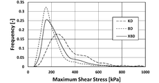
- Example 1 and Comparative Examples 1 and 2 it is a graph which shows the result about the maximum elongation stress in the simulation of an Example.
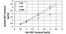
- Example 1 and Comparative Examples 1 and 2 it is a graph which shows the relationship between the setting value of CNT content, and a measured value.
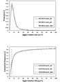
- Example 1 and Comparative Examples 1 and 2 it is a graph which shows the size distribution of the aggregate.
- 4 is a graph showing the ratio of CNT aggregates of 5 ⁇ m 2 or less in Example 1 and Comparative Examples 1 and 2 .
- Example 1 and Comparative Examples 1 and 2 it is a graph which shows the result of a dynamic viscoelasticity measurement.
- Example 1 and Comparative Examples 1 and 2 it is a graph which shows the result of a dynamic viscoelasticity measurement.
- Example 1 and Comparative Examples 1 and 2 it is a graph which shows the result about electroconductivity. In Example 1 and Comparative Examples 1 and 2, it is a graph which shows the result about a crystallinity degree. In Example 1 and Comparative Examples 1 and 2, it is a graph which shows the result about an elasticity modulus. In Example 1 and Comparative Examples 1 and 2, it is a graph which shows the result about tensile strength. 4 is a table summarizing evaluation test results in Example 1 and Comparative Examples 1 and 2.
- FIG. FIG. 3 is a schematic view of a twin-screw kneading extruder used in preparing master batches in Examples 2 to 8.
- FIG. 6 is a graph showing measured values of pressure loss with respect to temperature and analytical values by simulation for Examples 2 to 8.
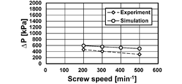
- FIG. 6 is a graph showing measured values of pressure loss with respect to screw rotation speed and analysis values by simulation in Examples 2 to 8.
- 6 is a graph showing measured values of pressure loss with respect to the processing amount and analysis values by simulation in Examples 2 to 8.
- 6 is a graph showing the relationship between the product of viscosity and flow rate and pressure loss for Examples 2 to 8.
- 6 is a graph showing the relationship between pressure loss and SME for Examples 2 to 8.
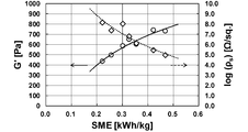
- 6 is a graph showing the relationship between viscoelastic properties and surface resistivity for Examples 2 to 8.
- 6 is a graph showing the results of a tensile test for Examples 2 to 8.
- 6 is a graph showing the results of morphology observation for Examples 2 to 8.
- 6 is a graph showing the size distribution of aggregates in Examples 2 to 8.
- 6 is a graph showing the ratio of SWCNT aggregates of 20 ⁇ m 2 or less in Examples 2 to 8.
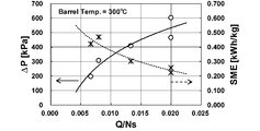
- 6 is a graph showing the relationship between Q / Ns and pressure loss for Examples 2 to 15.
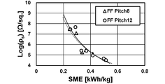
- 6 is a graph showing the relationship between SME and surface resistivity for Examples 2 to 15.
- FIG. 6 is a graph showing the relationship between Q / Ns and pressure loss for Examples 2 to 8 and Examples 16 to 22. 6 is a graph showing the relationship between SME and surface resistivity for Examples 2 to 8 and Examples 16 to 22.
- FIG. 4 is a schematic diagram of a twin-screw kneading extruder showing the arrangement position of each disk-type segment in Examples 23 to 32. 32 is a photograph of a disk-type segment used in Examples 28-32.
- FIG. 9 is a schematic diagram of a twin-screw kneading extruder showing the arrangement position of each disk-type segment in Comparative Examples 3 to 7.
- 6 is a graph showing pressure loss data for Examples 23 to 32 and Comparative Examples 3 to 7.
- 6 is a graph showing discharge temperature data for Examples 23 to 32 and Comparative Examples 3 to 7.
- 6 is a graph showing the relationship between PC dispersion diameter and haze value for Examples 23 to 32 and Comparative Examples 3 to 7.
- 6 is a graph showing measurement results of the droplet diameter of PC for Examples 23 to 32 and Comparative Examples 3 to 7.
- 6 is a graph showing relative haze values (relative values with respect to the haze value of PMMA alone) for Examples 23 to 32 and Comparative Examples 3 to 7.
- a multi-axis kneader according to the present invention a method for producing a nanocomposite using this multi-axis kneader, and preferred embodiments of disk-type segments used in these will be described in detail.
- the scope of the present invention is not limited to these explanations, and modifications other than the following examples can be made as appropriate without departing from the spirit of the present invention.
- the multi-axis kneader according to the present invention is not limited to the extrusion molding machine, and similarly, a kneading mechanism using a plurality of kneading screws.
- twin-screw kneader will be described as an example. However, those skilled in the art can easily apply the present invention to a multi-screw kneader having three or more axes from the technical common sense and the following description. You will get. Furthermore, the various dimensions described below are only examples, and those skilled in the art can easily apply the present invention to various multi-screw kneaders having different scales from the following examples based on common general technical knowledge and the following examples. Can be applied.
- FIG. 1 A twin-screw kneading extruder according to one embodiment of the present invention is shown in FIG.
- the twin-screw kneading extruder 1 has the same basic configuration as that of the prior art, and includes a hollow barrel 11, a hopper 12 for supplying resin into the barrel 11, and resin addition into the barrel 11.
- An additive inlet 13 (side feeder) for supplying the agent and a vent 14 for deaeration and the like are provided.
- a kneading screw 21 is disposed in the barrel 11 along the axial direction. Since the kneading extruder of the present embodiment is biaxial, two kneading screws are paired.
- a disk-type segment 22 is arranged at an intermediate position of the kneading screw 21 and downstream of the additive inlet 13. The “intermediate position” does not necessarily mean the center, but simply means that it is not an entrance or exit position. In this embodiment, only one disk-type segment 22 is provided, but a plurality of disk-type segments 22 may be arranged. In this case, they may be arranged continuously or at intervals. Since the disk-type segment 22 is a segment type, pressure control, its position, number, etc. can be set freely.
- the resin supplied from the hopper 12 is conveyed by the kneading screw 21 while being kneaded in the axial direction from upstream (left side in FIG. 1) to downstream (right side in FIG. 1). At that time, the resin additive is supplied from the additive inlet 13 along the way. From the vent 14, the gas generated during the kneading is discharged.
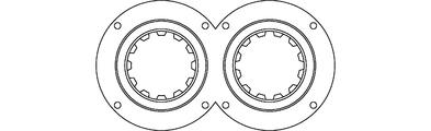
- the disc-shaped segment 22 has a cross-sectional shape that is substantially the same shape as the inner cross-section of the barrel 11 so as to partition the inside of the barrel 11.
- the disk-type segment 22 has a cross-sectional shape in which two circles are partially overlapped as shown in FIG. 2, and the barrel 11 has a similar inner cross-sectional shape.
- the disc-type segment 22 does not allow the kneaded material to pass through the clearance with the inner wall of the barrel 11 as in a conventional kneading disc, but allows the kneaded material to pass through a small hole 221a (described later). There is no need to provide a gap between the inner wall of the barrel 11. However, a gap may be provided to facilitate the insertion of the disk-type segment 22 into the barrel 11.
- the disk-type segment 22 includes a disk main body 221 and a shaft penetrating portion 222 through which the rotating shaft 21 a of the kneading screw 21 passes rotatably.
- the shaft penetrating part 222 include ball bearings, sleeve bearings, roller bearings, and the like.
- the disk-type segment 22 does not rotate with the rotation of the kneading screw 21 and is in a fixed state at the time of kneading extrusion.
- a large number of small holes 221 a serving as channels for the kneaded material are formed around the shaft penetrating portion 222.
- the disk-type segment in the multi-axis kneader of the present invention is a fixed type that does not rotate with the rotation of the kneading screw, and the kneaded material passes through the small holes very efficiently. . Since two discs are separated and each does not leak between the discs as in the conventional blister disc rotating with the rotation of the kneading screw, a high pressure loss can be brought about.
- this inventor has acquired the knowledge that the dispersibility of a resin additive improves by extending
- the design pressure resistance and dispersibility of the multi-shaft kneader are also taken into consideration for the diameter, axial thickness and number of the small holes 221a, the total opening area of the small holes 221a on the resin flow inlet side, the position, the extrusion speed, and the like. It is desirable to design. For example, although the pressure loss can be increased by increasing the thickness of the small hole, it is desirable that the inside of the small hole be as thin as possible in order to avoid shear heat generation because of the pure shearing action.
- the diameter of the small holes is usually determined in consideration of the size of the resin additive nanoparticles. A preferable range from such a viewpoint will be described below as an example. That is, for example, the diameter of the small hole 221a is set to 0.5 to 1.5 mm, and the thickness of the small hole 221a in the axial direction is 1/12 to the ratio (L / D) of the thickness (L) to the screw diameter (D).
- the number of small holes 221a can be 2 to 64.
- the total opening area of the small holes 221a on the resin flow inlet side can be 4 to 20% of the inner cross-sectional area of the barrel 11, for example. It is preferably within 20%, more preferably within 10%.
- 30 small holes 221a are arranged in a line in a concentric manner with respect to each shaft penetrating portion 222. Unlike this, two or more rows of small holes may be arranged. Further, a small hole is not formed between the shaft penetrating part 222 and the shaft penetrating part 222. However, the present invention is not limited to this, and a small hole is formed between the shaft penetrating part 222 and the shaft penetrating part 222. May be. Further, in the above-described embodiment, the additive inlet 13 is provided in the middle of the barrel 11 and the resin additive is supplied therefrom, but unlike this, the resin and the resin additive are simultaneously supplied from the hopper 12. It is also good.
- the said embodiment knead
- this invention is not limited to this, Kneading
- it can be applied to kneading of a polymer blend (alloy).
- the polymer blend includes a compatible system and an incompatible system, and the degree of compatibility in the compatible system varies, but the present invention is applicable to any of them. More details are as follows.
- ⁇ m matrix phase viscosity
- ⁇ d disperse phase viscosity
- v interfacial tension
- d initial droplet diameter
- the present invention which is excellent in elongation fluidity and can suppress shearing heat generation is suitable for polymer blends, particularly polymer blends having LCST type phase diagrams.
- a preferable polymer blend for example, a polymer blend of polymethyl methacrylate (matrix) and polycarbonate (dispersed phase) can be mentioned.
- This polymer blend utilizes the high rigidity and transparency of polymethyl methacrylate and the high impact and heat resistance of polycarbonate, and exhibits high heat resistance while maintaining transparency and mechanical properties.
- This polymer blend has an LCST type phase diagram, and the LCST is about 285 ° C.
- a plurality of disk-type segments in the multi-axis kneader of the present invention may be arranged, and the positions thereof can be freely set.
- the vacuum pump if there is only one disk-type segment, the vacuum pump is disposed at position A as shown in FIG.
- a plurality of disk-type segments are used, as shown in FIG. 7, not only the position of B1 but also the position of B2 (behind the disk-type segment), a vacuum pump is disposed and devolatilized. Can do. Since the arrangement of the disk-type segments can be freely set, the devolatilization position can be freely changed.
- the method for producing a nanocomposite of the present invention includes a step of adding nanoparticles as a resin additive using the multiaxial kneader of the present invention as described above. Since the multi-axis kneader of the present invention is excellent in nanodispersibility, it is particularly suitable for such a method for producing a nanocomposite.
- the resin is not particularly limited, and examples thereof include general thermoplastic resins such as general-purpose plastics (such as polypropylene), general-purpose engineering plastics, and super-engineering plastics.
- the nanoparticles are not particularly limited, and examples thereof include carbon nanotubes, carbon nanofibers, cellulose nanofibers, graphene, nanoclays, and carbon black.
- the multi-axis kneader according to the present invention the method for producing a nanocomposite using this multi-axis kneader, and the disk-type segments used in these will be described with reference to examples, but the present invention is limited to these examples. Is not to be done.
- Example 1 Using a twin-screw kneading extruder “ZSK18 MEGALab” (manufactured by Coperion, screw diameter 18 mm, L / D: 40), a disk-type segment (hereinafter referred to as “XBD” (hereinafter, “Fixed Blistering Disk”) shown in FIG. ) And a kneading extrusion.
- XBD disk-type segment
- Fixed Blistering Disk a disk-type segment
- FIG. 8 the number of small holes in the XBD is 30.
- the diameter of the small hole is 1 mm
- the axial width (thickness) of the small hole is 3 mm (the axial width of the disk including other portions is 7 mm).
- polypropylene “Prime Polypro (registered trademark) J108M” (manufactured by Prime Polymer Co., Ltd., homopolymer, MFR: 45 g / 10 min (230 ° C.)) is used as a resin, and a resin additive (nanofiller) ) Carbon nanotubes (CNT) “NC7000” (manufactured by NANOCYL, Inc., multi-walled carbon nanotubes, average diameter 9.5 nm, average length 1.5 ⁇ m, aspect ratio 160) were used.
- the arrangement position of XBD in the biaxial kneading extruder was as shown in FIG.
- the kneading and extrusion conditions were a barrel temperature of 200 ° C., a screw rotation speed of 250 rpm, and an input amount of 5.4 kg / h.
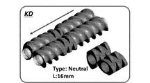
- Kneading extrusion was performed in the same manner as in Example 1 except that a kneading disk (hereinafter abbreviated as “KD”) shown in FIG. 10 was used instead of XBD. As shown in FIG. 10, five discs shifted by 90 ° are continuously formed, and the width (thickness) in the axial direction is 16 mm as a whole. In addition, the arrangement position of KD in the twin-screw kneading extruder is also shown in FIG.
- KD kneading disk
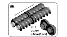
- BD blistering Disk
- the diameter of the small hole is 1 mm
- the axial width (thickness) of the small hole is 3 mm (the axial width of the disk including other portions is 9 mm).
- the arrangement position of the BD in the twin-screw kneading extruder is also shown in FIG.
- Example 1 and Comparative Examples 1 and 2 were evaluated. The results are shown below.
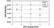
- the results of Example 1 and Comparative Examples 1 and 2 are shown in FIG. 12, with the addition rate (% by weight) of CNTs as the horizontal axis and the specific mechanical energy (SME: Specific Mechanical Energy) (kWh / kg) as the vertical axis.
- SME Specific Mechanical Energy
- the results of Example 1 and Comparative Examples 1 and 2 are shown in FIG. 13 with the addition rate (% by weight) of CNT as the horizontal axis and the resin temperature (° C.) as the vertical axis.
- FIG. 14 shows the results of Example 1 and Comparative Examples 1 and 2, with SME (kWh / kg) as the horizontal axis and the resin temperature (° C.) as the vertical axis.
- Example 1 using XBD SME was the highest.
- FIG. 13 in Example 1 using XBD and Comparative Example 2 using BD, the increase in the resin temperature is suppressed and shearing heat generation is suppressed compared to Comparative Example 1 using KD. I found out.
- the heat generation temperature is lower than the applied energy. This can be understood as an effect of elongational flow.
- the fluid is incompressible and non-Newtonian. Inertia and gravity are negligible. The fluid adheres to the barrel surface. The flow is constant temperature.
- Shear viscosity and elongational viscosity are each defined by the following equations. These are based on the shear viscosity curve and elongational viscosity curve shown in FIG. 15 for a carbon nanotube concentration of 1.0% by weight.
- Shear stress and elongation stress are defined by the following formulas.
- Optical microscope and scanning electron microscope (SEM) Dispersibility was locally evaluated by an optical microscope and a scanning electron microscope (SEM).
- a sample thickness 20 ⁇ m
- a sample was prepared with a microtome “RM2265” (manufactured by Leica), and a cross section was observed with a digital microscope “VHX-5000” (manufactured by Keyence) (magnification 200 ⁇ ).
- the area of the aggregate (1 ⁇ m 2 or more) was measured by image analysis software “SigmaScan Pro5” (manufactured by Hulinks).
- Example 1 For Example 1 (XBD), Comparative Example 1 (KD), and Comparative Example 2 (BD), the relationship between the set value of the CNT content and the measured value is shown in Table 1 and FIG.
- FIG. 24 shows the size distribution of the aggregates when the CNT content (set value) is 0.5% by weight. From this result, it was found that Example 1 (XBD) had a better CNT dispersion state than Comparative Example 1 (KD).
- Example 1 Example 1 (XBD)> Comparative example 2 (BD)> Comparative example 1 (KD) It can be said.
- Example 1 it was found that the dispersibility was improved by about 8% compared to Comparative Example 1, and it was found that the dispersion state was particularly good at a low concentration.
- Conductivity test CNT dispersion was evaluated over the entire area by measuring volume resistivity (based on JIS K7194). For this measurement, a resistivity meter “HIRESTA UP” (manufactured by Mitsubishi Chemical Analytech Co., Ltd.) was used.
- Example 1 (XBD) was lower than that of Comparative Example 1 (KD).
- the CNT network is almost proportional to the dispersion state (Takahiro Takahashi, Ken Yasuda, Takahiro Okubo, Hiroshi Kanno, Koichiro Yonetake, “Composite function of carbon nanotube and polymer”, Carbon TANSO Vol.2006 (2006) No.223 P194-205), it can be said that the smaller the volume resistivity value, the more the dispersion is promoted. Therefore, Dispersion state: Example 1 (XBD)> Comparative example 1 (KD)> Comparative example 2 (BD) It can be said.
- Tensile test JIS K7161 1A test piece was produced using an injection molding machine “PLASTR ET-40V” (manufactured by Toyo Kikai Metal Co., Ltd.). According to JIS K7161, five measurements were performed and the elastic modulus and tensile strength were measured.
- Example 1 XBD
- Comparative Example 2 BD
- Comparative Example 1 KD It can be said. It can be understood that the above results are because the thermal degradation of the polypropylene itself is suppressed and the crystallinity is improved as the dispersibility is improved. In particular, the effect of improving the mechanical strength was high on the low concentration side.
- the multi-axis kneader of the present invention the method for producing a nanocomposite using this multi-axis kneader, and the disk-type segment used therein can avoid resin leakage between disks as in Comparative Example 2, while suppressing shearing. It can be said that it specializes in elongational flow (while suppressing shearing heat generation).
- Example 2 to 8 Using a twin-screw kneading extruder “ZSK18 MEGALab” (manufactured by Coperion, screw diameter 18 mm, L / D: 40), a disk-type segment was placed in the barrel and kneading extrusion was performed. Details are as follows.
- cycloolefin polymer “ZEONOR (registered trademark) 1420R” (manufactured by Nippon Zeon Co., Ltd., amorphous resin, glass transition point 136 ° C., melt flow rate 20 g / 10 min (280 ° C.)) is used as the resin.
- a resin additive nanonanofiller
- single-walled carbon nanotube SWCNT
- ZEONANO registered trademark
- COP was supplied from the hopper, SWCNT was added from the additive inlet, and kneading extrusion was performed to prepare a master batch.
- Melting (KD) is a kneading disk (shown in FIG. 10) used for melting.
- COP was added to the master batch to adjust the concentration so that SWCNT was 0.5 wt%.
- the screw is a full flight screw (FF), and the screw pitch (interval indicated by a in FIG. 35) is 12 mm.
- “Melting (KD)” is a kneading disk (shown in FIG. 10) used for melting.
- the XBD is shown in FIG. 8.
- the number of small holes in the XBD is 30, the diameter of the small holes is 1 mm, and the axial width (thickness) of the small holes is 3 mm (the axial direction of the disk including other parts) Is 7 mm).
- the kneading extrusion conditions in the above operation are as shown in the table below.
- v velocity vector
- ⁇ relative compression factor
- ⁇ shear viscosity
- H step function
- ⁇ a inertia term
- T Surplus stress tensor
- D Deformation rate tensor.
- Optical microscope and scanning electron microscope (SEM) Dispersibility was locally evaluated by an optical microscope and a scanning electron microscope (SEM).
- a sample (thickness 2 ⁇ m) was prepared with a microtome (manufactured by Japan Microtome Research Co., Ltd., RMD-5 type), and the cross section was observed with an optical microscope (manufactured by MEIJI TECHNO, MT9400) (magnification 230 times).
- SEM observation was performed by observing a cross section of the tensile test piece at an acceleration voltage of 10.0 kV using a scanning electron microscope FE-SEM (manufactured by JEOL, JSM-7001FD).
- the area of the aggregate (1 ⁇ m 2 or more) was measured by image analysis software “SigmaScan Pro5” (manufactured by Hulinks).
- Tensile test JIS K7161 1A test piece was produced using an injection molding machine “PLASTR ET-40V” (manufactured by Toyo Kikai Metal Co., Ltd.). In accordance with JIS K7161, seven measurements were made and the elastic modulus, tensile strength and elongation at break were measured.
- the Power-law law is expressed by the following formula.
- K Viscosity coefficient
- Q Flow rate
- n Power-law index
- N Number of through-holes
- R Through-hole radius
- L Through-hole length
- changing the barrel temperature and the rotational speed which are kneading conditions, is synonymous with changing the viscosity from the temperature dependence and shear rate dependence of the viscosity.
- changing the processing amount is synonymous with changing the flow rate.
- ⁇ Shear rate / Elongation rate at disc type segment through hole> 40 to 42 show the analysis results of the shear rate and the stretch rate at the disk-type segment through-holes based on the simulation of COP / SWCNT kneading extrusion. From the results shown in the figure, the barrel temperature (resin temperature) does not affect the strain rate (however, the stress increases), the screw rotational speed decreases with increasing strain rate, and the flow rate increases with increasing strain. It turns out that the speed increases. This tendency is similar to the pressure loss (the pressure loss and the acting stress are equivalent).
- FIG. 44 shows the relationship between viscoelastic properties and surface resistivity for Examples 2 to 8. From the results shown in the figure, it was found that G ′ increased with an increase in SME (decrease in Q / Ns), and the surface resistivity decreased (conductivity improved). That is, SWCNT entanglement depends on SME.
- the pressure loss ( ⁇ p) occurring in the disk-type segment of the present invention is proportional to the product of viscosity and flow rate, and increases with increasing Q / Ns.
- the viscosity and flow rate can be changed by changing the kneading conditions.
- the tensile strength is greatly improved as ⁇ p increases.
- the conductivity improves with increasing SME. From this fact, it was found that ⁇ p promotes macro uniform dispersion of the dispersion material, whereas SME promotes micro dispersion. Although SME and ⁇ p are in a reciprocal relationship, it is difficult to achieve both of them. However, reducing the number of small holes from 30 to 8 results in an increase in pressure loss. It was found that ⁇ p can be improved. On the other hand, it has been found that reducing the screw pitch is not very effective in improving ⁇ p.
- Examples 23 to 27 Using a twin-screw kneading extruder “ZSK18 MEGALab” (manufactured by Coperion, screw diameter 18 mm, L / D: 40), the disk type segment (XBD) shown in FIG. went. As shown in FIG. 8, the number of small holes in the XBD is 30. The diameter of the small hole is 1 mm, and the axial width (thickness) of the small hole is 3 mm (the axial width of the disk including other portions is 7 mm). Polymethyl methacrylate (PMMA) (manufactured by Mitsubishi Chemical Corporation, VH001) was used as the matrix of the polymer blend.
- PMMA Polymethyl methacrylate
- the density is 1.19 g / cm 3 and the melt flow rate (MFR) is 2.0 g / 10 min (230 ° C., 3.73 N). Further, polycarbonate (PC) (manufactured by Mitsubishi Engineering Plastics Co., Ltd., H-4000) was used as the dispersed phase. The density is 1.20 g / cm 3 and the MFR is 63 g / 10 min (300 ° C., 1.20 kgf). PMMA and PC were dry blended at a ratio of PC of 4% by weight, and this was supplied from a hopper to a twin-screw kneading extruder to perform kneading extrusion.
- ⁇ PC dispersion diameter in PMMA> The results of TEM observation are shown in FIG.
- the droplet diameter d pc [nm] is an average value of about 300. From the results shown in the figure, it was found that the dispersion diameter of PC tends to decrease as Q / Ns increases.
- FIG. 60 shows the relationship between the PC dispersion diameter and the haze value for Examples 23 to 32 and Comparative Examples 3 to 7. Moreover, the relative haze value (relative value to the haze value of PMMA alone) is shown in FIG. From the results shown in the figure, it was found that using XBD had a smaller PC droplet diameter and, as a result, a smaller haze value (higher transparency) than using KD.
- the disk-type segment of the present invention can provide a high pressure loss while suppressing shearing heat generation, thereby enabling a process for improving heat resistance while maintaining transparency. That is, it has been found that the disk-type segment of the present invention is extremely effective in application to a polymer blend.
Landscapes
- Engineering & Computer Science (AREA)
- Mechanical Engineering (AREA)
- Manufacturing & Machinery (AREA)
- Processing And Handling Of Plastics And Other Materials For Molding In General (AREA)
- Extrusion Moulding Of Plastics Or The Like (AREA)
- Processes Of Treating Macromolecular Substances (AREA)
Abstract
L'invention concerne : un malaxeur multi-vis dans lequel des actions d'extension et d'écoulement qui agissent avant et après des petits trous dans un segment en forme de disque ayant les petits trous peuvent être suffisamment démontrées; une méthode de production d'un nano-composite à l'aide du malaxeur multi-vis; et un segment en forme de disque utilisé pour ledit malaxeur et ladite méthode. Ce malaxeur à vis multiples est pourvu d'une pluralité de vis de malaxage et d'un segment en forme de disque dans un cylindre. Le segment en forme de disque sépare l'intérieur du cylindre au niveau d'un côté aval à partir d'une partie d'alimentation en matériau de malaxage, et est pourvu de: une pluralité de sections de pénétration d'arbre à travers lesquelles l'arbre de rotation de chaque vis de malaxage passe d'une manière rotative; et une pluralité de petits trous qui sont perforés autour des sections de pénétration d'arbre et servent de passages d'écoulement pour le matériau de malaxage. Cette méthode de production d'un nano-composite comprend une étape d'alimentation de nanoparticules en tant qu'additif de résine à l'aide du malaxeur multi-vis. Ce segment en forme de disque est pourvu des sections de pénétration d'arbre et de la pluralité de petits trous.
Priority Applications (4)
| Application Number | Priority Date | Filing Date | Title |
|---|---|---|---|
| CN201880012536.1A CN110300649B (zh) | 2017-02-22 | 2018-02-21 | 多轴混炼机和使用了该多轴混炼机的纳米复合材料的制造方法以及用于它们的盘形件 |
| JP2019501381A JP6532628B2 (ja) | 2017-02-22 | 2018-02-21 | 多軸混練機及びこの多軸混練機を用いたナノコンポジットの製造方法並びにこれらに用いるディスク型セグメント |
| EP18757298.7A EP3587060B1 (fr) | 2017-02-22 | 2018-02-21 | Segment en forme de disque, et méthode de fabrication de nano-composite utilisant ledit segment |
| US16/548,132 US11938657B2 (en) | 2017-02-22 | 2019-08-22 | Multi-screw kneader and method for producing nano-composite using said multi-screw kneader, and disk-shaped segment used for said kneader and said method |
Applications Claiming Priority (2)
| Application Number | Priority Date | Filing Date | Title |
|---|---|---|---|
| JP2017030841 | 2017-02-22 | ||
| JP2017-030841 | 2017-02-22 |
Related Child Applications (1)
| Application Number | Title | Priority Date | Filing Date |
|---|---|---|---|
| US16/548,132 Continuation US11938657B2 (en) | 2017-02-22 | 2019-08-22 | Multi-screw kneader and method for producing nano-composite using said multi-screw kneader, and disk-shaped segment used for said kneader and said method |
Publications (1)
| Publication Number | Publication Date |
|---|---|
| WO2018155502A1 true WO2018155502A1 (fr) | 2018-08-30 |
Family
ID=63253266
Family Applications (1)
| Application Number | Title | Priority Date | Filing Date |
|---|---|---|---|
| PCT/JP2018/006270 Ceased WO2018155502A1 (fr) | 2017-02-22 | 2018-02-21 | Malaxeur multi-vis et méthode de fabrication de nano-composite utilisant ledit malaxeur multi-vis, et segment en forme de disque utilisé pour ledit malaxeur et ladite méthode |
Country Status (5)
| Country | Link |
|---|---|
| US (1) | US11938657B2 (fr) |
| EP (1) | EP3587060B1 (fr) |
| JP (1) | JP6532628B2 (fr) |
| CN (1) | CN110300649B (fr) |
| WO (1) | WO2018155502A1 (fr) |
Families Citing this family (1)
| Publication number | Priority date | Publication date | Assignee | Title |
|---|---|---|---|---|
| CN112388861B (zh) * | 2020-10-29 | 2022-05-17 | 无锡市瑞澳矿业科技有限公司 | 一种基于温差变换的双辊式橡胶开炼装置 |
Citations (4)
| Publication number | Priority date | Publication date | Assignee | Title |
|---|---|---|---|---|
| JPS5948136A (ja) * | 1982-09-13 | 1984-03-19 | Japan Synthetic Rubber Co Ltd | ベント押出機 |
| JPH1110709A (ja) | 1997-06-23 | 1999-01-19 | Sagara Kogyo Kk | ニーディングディスク及びニーディングディスクの製造方法 |
| WO1999061213A1 (fr) * | 1998-05-25 | 1999-12-02 | Sato Iron Works Co., Ltd. | Dispositif de petrissage du type faible friction |
| JP2013535358A (ja) * | 2010-07-23 | 2013-09-12 | ランクセス・ドイチュランド・ゲーエムベーハー | ダイプレートが一体化された押出機およびポリマー混合物を脱気するための方法 |
Family Cites Families (7)
| Publication number | Priority date | Publication date | Assignee | Title |
|---|---|---|---|---|
| BE523318A (fr) * | 1953-07-30 | 1900-01-01 | ||
| DE1554751B1 (de) * | 1966-09-10 | 1971-01-07 | Kestermann Maschf Rolf | Schnecken-Strangpresse |
| US3447582A (en) * | 1967-08-01 | 1969-06-03 | Egan & Co Frank W | Apparatus for treating polymers and the like |
| JPH08104899A (ja) * | 1994-10-04 | 1996-04-23 | Sato Tekkosho:Kk | 多段式真空練り出し成形装置 |
| US5962036A (en) * | 1998-01-08 | 1999-10-05 | Wenger Manufacturing, Inc. | Twin screw extruder with high-speed bearing support |
| US20150275063A1 (en) * | 2012-09-19 | 2015-10-01 | Chandrashekar Raman | Thermally conductive plastic compositions, extrusion apparatus and methods for making thermally conductive plastics |
| PL2921279T3 (pl) * | 2014-03-20 | 2017-08-31 | Coperion Gmbh | Urządzenie i sposób homogenizacji roztopionych materiałów z tworzyw sztucznych |
-
2018
- 2018-02-21 JP JP2019501381A patent/JP6532628B2/ja active Active
- 2018-02-21 CN CN201880012536.1A patent/CN110300649B/zh active Active
- 2018-02-21 EP EP18757298.7A patent/EP3587060B1/fr active Active
- 2018-02-21 WO PCT/JP2018/006270 patent/WO2018155502A1/fr not_active Ceased
-
2019
- 2019-08-22 US US16/548,132 patent/US11938657B2/en active Active
Patent Citations (4)
| Publication number | Priority date | Publication date | Assignee | Title |
|---|---|---|---|---|
| JPS5948136A (ja) * | 1982-09-13 | 1984-03-19 | Japan Synthetic Rubber Co Ltd | ベント押出機 |
| JPH1110709A (ja) | 1997-06-23 | 1999-01-19 | Sagara Kogyo Kk | ニーディングディスク及びニーディングディスクの製造方法 |
| WO1999061213A1 (fr) * | 1998-05-25 | 1999-12-02 | Sato Iron Works Co., Ltd. | Dispositif de petrissage du type faible friction |
| JP2013535358A (ja) * | 2010-07-23 | 2013-09-12 | ランクセス・ドイチュランド・ゲーエムベーハー | ダイプレートが一体化された押出機およびポリマー混合物を脱気するための方法 |
Non-Patent Citations (5)
| Title |
|---|
| H.P. GRACE, CHEMICAL ENGINEERING COMMUNICATIONS, vol. 14, no. 3-6, 1982, pages 225 - 277 |
| See also references of EP3587060A4 |
| TANAKA, TATSUYA: "Changes of the mixing technology/System by a twin screw extruder and application to nano filler dispersion techniques", BANDO TECHNICAL REPORT NO. 18, vol. 2, no. 18, 3 March 2014 (2014-03-03), pages 8, XP9516319 * |
| TATSUHIRO TAKAHASHITAKESHI YASUDATAKAHIRO OOKUBOHIROSHI AWANOKOICHIRO YONETAKE: "Functionalization of carbon nanotube/polymer composite", TANSO, vol. 2006, no. 223, 2006, pages 194 - 205 |
| TATSUYA TANAKA: "Bando Technical Report", 2014, BANDO CHEMICAL INDUSTRIES, LTD., article "Nijiku Konren Oshidashiki ni yoru Konren Gijutsu/ Souchi no Hensen oyobi Nanofira Bunsan Gijutsu no Oyo (Kneading technique using twin-screw kneading extruder, transition of apparatus, and application of nano filler dispersion technology", pages: 2 - 8 |
Also Published As
| Publication number | Publication date |
|---|---|
| EP3587060A1 (fr) | 2020-01-01 |
| JPWO2018155502A1 (ja) | 2019-06-27 |
| EP3587060B1 (fr) | 2022-04-06 |
| CN110300649A (zh) | 2019-10-01 |
| EP3587060A4 (fr) | 2020-12-16 |
| CN110300649B (zh) | 2022-03-11 |
| US20190389092A1 (en) | 2019-12-26 |
| JP6532628B2 (ja) | 2019-06-26 |
| US11938657B2 (en) | 2024-03-26 |
Similar Documents
| Publication | Publication Date | Title |
|---|---|---|
| Jimenez et al. | Electrically conductive polymer nanocomposites of polymethylmethacrylate and carbon nanofibers prepared by chaotic mixing | |
| Novais et al. | The effect of flow type and chemical functionalization on the dispersion of carbon nanofiber agglomerates in polypropylene | |
| Vatansever et al. | Development of CNC-reinforced PBAT nanocomposites with reduced percolation threshold: a comparative study on the preparation method | |
| Mishra et al. | Manipulation of thermo-mechanical, morphological and electrical properties of PP/PET polymer blend using MWCNT as nano compatibilizer: a comprehensive study of hybrid nanocomposites | |
| Lee et al. | Effect of fillers on the structure and mechanical properties of LCP/PP/SiO2 in-situ hybrid nanocomposites | |
| Sarul et al. | Effect of mixing strategy on the structure-properties of the PLA/PBAT blends incorporated with CNC | |
| WO2017169482A1 (fr) | Composition de résine thermoplastique et procédé de production d'une composition de résine thermoplastique | |
| Wang et al. | Morphology evolutions and mechanical properties of in situ fibrillar polylactic acid/thermoplastic polyurethane blends fabricated by fused deposition modeling | |
| Zhang et al. | Selective localization of starch nanocrystals in the biodegradable nanocomposites probed by crystallization temperatures | |
| WO2013111862A1 (fr) | Procédé de production d'un lot maître pour résine conductrice, et lot maître | |
| Wang et al. | Compatibilization of poly (lactic acid)/ethylene‐propylene‐diene rubber blends by using organic montmorillonite as a compatibilizer | |
| Ab Ghani et al. | The evaluation of mechanical properties graphene nanoplatelets reinforced polylactic acid nanocomposites | |
| Doagou-Rad et al. | Influence of processing conditions on the mechanical behavior of MWCNT reinforced thermoplastic nanocomposites | |
| Kong et al. | Elongation thinning and morphology deformation of nanoparticle-filled polypropylene/polystyrene blends in elongational flow | |
| Zhan et al. | Electrical, thermal, and mechanical properties of polyarylene ether nitriles/graphite nanosheets nanocomposites prepared by masterbatch route | |
| Arigbabowo et al. | Fused filament fabrication of polyamide 6 nanographene composite for electrostatic discharge applications | |
| JP6873360B2 (ja) | 熱可塑性樹脂組成物 | |
| JP6532628B2 (ja) | 多軸混練機及びこの多軸混練機を用いたナノコンポジットの製造方法並びにこれらに用いるディスク型セグメント | |
| Fernandez et al. | The effect of nano, micro and dual scale filler reinforcement on the morphology, mechanical and barrier properties of polypropylene composites | |
| TWI721556B (zh) | 導電樹脂組合物及其製備方法 | |
| Rizvi et al. | Processing and properties of melt spun polylactide–multiwall carbon nanotube fiber composites | |
| Ding et al. | Hierarchical structure of thermotropic liquid crystalline polymer formed in blends jointly by dynamic and thermodynamic driving forces | |
| Tanoue et al. | Characterization of polypropylene/magnesium oxide/vapor-grown carbon fiber composites prepared by melt compounding | |
| Ata et al. | Effect of matrix polymer viscosity on nanofiller exfoliation during compounding | |
| Heidari Golfazani et al. | The role of nanoclay partitioning on microfibril morphology development in polypropylene/polyamide 6 nanocomposite fibers |
Legal Events
| Date | Code | Title | Description |
|---|---|---|---|
| DPE1 | Request for preliminary examination filed after expiration of 19th month from priority date (pct application filed from 20040101) | ||
| 121 | Ep: the epo has been informed by wipo that ep was designated in this application |
Ref document number: 18757298 Country of ref document: EP Kind code of ref document: A1 |
|
| ENP | Entry into the national phase |
Ref document number: 2019501381 Country of ref document: JP Kind code of ref document: A |
|
| NENP | Non-entry into the national phase |
Ref country code: DE |
|
| ENP | Entry into the national phase |
Ref document number: 2018757298 Country of ref document: EP Effective date: 20190923 |