WO2018155502A1 - 多軸混練機及びこの多軸混練機を用いたナノコンポジットの製造方法並びにこれらに用いるディスク型セグメント - Google Patents
多軸混練機及びこの多軸混練機を用いたナノコンポジットの製造方法並びにこれらに用いるディスク型セグメント Download PDFInfo
- Publication number
- WO2018155502A1 WO2018155502A1 PCT/JP2018/006270 JP2018006270W WO2018155502A1 WO 2018155502 A1 WO2018155502 A1 WO 2018155502A1 JP 2018006270 W JP2018006270 W JP 2018006270W WO 2018155502 A1 WO2018155502 A1 WO 2018155502A1
- Authority
- WO
- WIPO (PCT)
- Prior art keywords
- kneading
- disk
- kneader
- screw
- barrel
- Prior art date
- Legal status (The legal status is an assumption and is not a legal conclusion. Google has not performed a legal analysis and makes no representation as to the accuracy of the status listed.)
- Ceased
Links
Images





















Classifications
-
- B—PERFORMING OPERATIONS; TRANSPORTING
- B29—WORKING OF PLASTICS; WORKING OF SUBSTANCES IN A PLASTIC STATE IN GENERAL
- B29B—PREPARATION OR PRETREATMENT OF THE MATERIAL TO BE SHAPED; MAKING GRANULES OR PREFORMS; RECOVERY OF PLASTICS OR OTHER CONSTITUENTS OF WASTE MATERIAL CONTAINING PLASTICS
- B29B7/00—Mixing; Kneading
- B29B7/30—Mixing; Kneading continuous, with mechanical mixing or kneading devices
- B29B7/34—Mixing; Kneading continuous, with mechanical mixing or kneading devices with movable mixing or kneading devices
- B29B7/38—Mixing; Kneading continuous, with mechanical mixing or kneading devices with movable mixing or kneading devices rotary
- B29B7/46—Mixing; Kneading continuous, with mechanical mixing or kneading devices with movable mixing or kneading devices rotary with more than one shaft
- B29B7/48—Mixing; Kneading continuous, with mechanical mixing or kneading devices with movable mixing or kneading devices rotary with more than one shaft with intermeshing devices, e.g. screws
- B29B7/482—Mixing; Kneading continuous, with mechanical mixing or kneading devices with movable mixing or kneading devices rotary with more than one shaft with intermeshing devices, e.g. screws provided with screw parts in addition to other mixing parts, e.g. paddles, gears, discs
-
- B—PERFORMING OPERATIONS; TRANSPORTING
- B29—WORKING OF PLASTICS; WORKING OF SUBSTANCES IN A PLASTIC STATE IN GENERAL
- B29B—PREPARATION OR PRETREATMENT OF THE MATERIAL TO BE SHAPED; MAKING GRANULES OR PREFORMS; RECOVERY OF PLASTICS OR OTHER CONSTITUENTS OF WASTE MATERIAL CONTAINING PLASTICS
- B29B7/00—Mixing; Kneading
- B29B7/30—Mixing; Kneading continuous, with mechanical mixing or kneading devices
- B29B7/34—Mixing; Kneading continuous, with mechanical mixing or kneading devices with movable mixing or kneading devices
- B29B7/38—Mixing; Kneading continuous, with mechanical mixing or kneading devices with movable mixing or kneading devices rotary
- B29B7/46—Mixing; Kneading continuous, with mechanical mixing or kneading devices with movable mixing or kneading devices rotary with more than one shaft
- B29B7/48—Mixing; Kneading continuous, with mechanical mixing or kneading devices with movable mixing or kneading devices rotary with more than one shaft with intermeshing devices, e.g. screws
- B29B7/482—Mixing; Kneading continuous, with mechanical mixing or kneading devices with movable mixing or kneading devices rotary with more than one shaft with intermeshing devices, e.g. screws provided with screw parts in addition to other mixing parts, e.g. paddles, gears, discs
- B29B7/483—Mixing; Kneading continuous, with mechanical mixing or kneading devices with movable mixing or kneading devices rotary with more than one shaft with intermeshing devices, e.g. screws provided with screw parts in addition to other mixing parts, e.g. paddles, gears, discs the other mixing parts being discs perpendicular to the screw axis
-
- B—PERFORMING OPERATIONS; TRANSPORTING
- B29—WORKING OF PLASTICS; WORKING OF SUBSTANCES IN A PLASTIC STATE IN GENERAL
- B29B—PREPARATION OR PRETREATMENT OF THE MATERIAL TO BE SHAPED; MAKING GRANULES OR PREFORMS; RECOVERY OF PLASTICS OR OTHER CONSTITUENTS OF WASTE MATERIAL CONTAINING PLASTICS
- B29B7/00—Mixing; Kneading
- B29B7/30—Mixing; Kneading continuous, with mechanical mixing or kneading devices
- B29B7/34—Mixing; Kneading continuous, with mechanical mixing or kneading devices with movable mixing or kneading devices
- B29B7/38—Mixing; Kneading continuous, with mechanical mixing or kneading devices with movable mixing or kneading devices rotary
- B29B7/46—Mixing; Kneading continuous, with mechanical mixing or kneading devices with movable mixing or kneading devices rotary with more than one shaft
- B29B7/48—Mixing; Kneading continuous, with mechanical mixing or kneading devices with movable mixing or kneading devices rotary with more than one shaft with intermeshing devices, e.g. screws
- B29B7/488—Parts, e.g. casings, sealings; Accessories, e.g. flow controlling or throttling devices
-
- B—PERFORMING OPERATIONS; TRANSPORTING
- B29—WORKING OF PLASTICS; WORKING OF SUBSTANCES IN A PLASTIC STATE IN GENERAL
- B29B—PREPARATION OR PRETREATMENT OF THE MATERIAL TO BE SHAPED; MAKING GRANULES OR PREFORMS; RECOVERY OF PLASTICS OR OTHER CONSTITUENTS OF WASTE MATERIAL CONTAINING PLASTICS
- B29B7/00—Mixing; Kneading
- B29B7/30—Mixing; Kneading continuous, with mechanical mixing or kneading devices
- B29B7/34—Mixing; Kneading continuous, with mechanical mixing or kneading devices with movable mixing or kneading devices
- B29B7/38—Mixing; Kneading continuous, with mechanical mixing or kneading devices with movable mixing or kneading devices rotary
- B29B7/46—Mixing; Kneading continuous, with mechanical mixing or kneading devices with movable mixing or kneading devices rotary with more than one shaft
- B29B7/48—Mixing; Kneading continuous, with mechanical mixing or kneading devices with movable mixing or kneading devices rotary with more than one shaft with intermeshing devices, e.g. screws
- B29B7/488—Parts, e.g. casings, sealings; Accessories, e.g. flow controlling or throttling devices
- B29B7/489—Screws
-
- B—PERFORMING OPERATIONS; TRANSPORTING
- B29—WORKING OF PLASTICS; WORKING OF SUBSTANCES IN A PLASTIC STATE IN GENERAL
- B29B—PREPARATION OR PRETREATMENT OF THE MATERIAL TO BE SHAPED; MAKING GRANULES OR PREFORMS; RECOVERY OF PLASTICS OR OTHER CONSTITUENTS OF WASTE MATERIAL CONTAINING PLASTICS
- B29B7/00—Mixing; Kneading
- B29B7/30—Mixing; Kneading continuous, with mechanical mixing or kneading devices
- B29B7/58—Component parts, details or accessories; Auxiliary operations
- B29B7/72—Measuring, controlling or regulating
- B29B7/726—Measuring properties of mixture, e.g. temperature or density
-
- B—PERFORMING OPERATIONS; TRANSPORTING
- B29—WORKING OF PLASTICS; WORKING OF SUBSTANCES IN A PLASTIC STATE IN GENERAL
- B29B—PREPARATION OR PRETREATMENT OF THE MATERIAL TO BE SHAPED; MAKING GRANULES OR PREFORMS; RECOVERY OF PLASTICS OR OTHER CONSTITUENTS OF WASTE MATERIAL CONTAINING PLASTICS
- B29B7/00—Mixing; Kneading
- B29B7/80—Component parts, details or accessories; Auxiliary operations
- B29B7/84—Venting or degassing ; Removing liquids, e.g. by evaporating components
- B29B7/845—Venting, degassing or removing evaporated components in devices with rotary stirrers
-
- B—PERFORMING OPERATIONS; TRANSPORTING
- B29—WORKING OF PLASTICS; WORKING OF SUBSTANCES IN A PLASTIC STATE IN GENERAL
- B29B—PREPARATION OR PRETREATMENT OF THE MATERIAL TO BE SHAPED; MAKING GRANULES OR PREFORMS; RECOVERY OF PLASTICS OR OTHER CONSTITUENTS OF WASTE MATERIAL CONTAINING PLASTICS
- B29B7/00—Mixing; Kneading
- B29B7/80—Component parts, details or accessories; Auxiliary operations
- B29B7/86—Component parts, details or accessories; Auxiliary operations for working at sub- or superatmospheric pressure
-
- B—PERFORMING OPERATIONS; TRANSPORTING
- B29—WORKING OF PLASTICS; WORKING OF SUBSTANCES IN A PLASTIC STATE IN GENERAL
- B29C—SHAPING OR JOINING OF PLASTICS; SHAPING OF MATERIAL IN A PLASTIC STATE, NOT OTHERWISE PROVIDED FOR; AFTER-TREATMENT OF THE SHAPED PRODUCTS, e.g. REPAIRING
- B29C48/00—Extrusion moulding, i.e. expressing the moulding material through a die or nozzle which imparts the desired form; Apparatus therefor
- B29C48/25—Component parts, details or accessories; Auxiliary operations
- B29C48/268—Throttling of the flow, e.g. for cooperating with plasticising elements or for degassing
-
- B—PERFORMING OPERATIONS; TRANSPORTING
- B29—WORKING OF PLASTICS; WORKING OF SUBSTANCES IN A PLASTIC STATE IN GENERAL
- B29C—SHAPING OR JOINING OF PLASTICS; SHAPING OF MATERIAL IN A PLASTIC STATE, NOT OTHERWISE PROVIDED FOR; AFTER-TREATMENT OF THE SHAPED PRODUCTS, e.g. REPAIRING
- B29C48/00—Extrusion moulding, i.e. expressing the moulding material through a die or nozzle which imparts the desired form; Apparatus therefor
- B29C48/25—Component parts, details or accessories; Auxiliary operations
- B29C48/36—Means for plasticising or homogenising the moulding material or forcing it through the nozzle or die
- B29C48/395—Means for plasticising or homogenising the moulding material or forcing it through the nozzle or die using screws surrounded by a cooperating barrel, e.g. single screw extruders
- B29C48/40—Means for plasticising or homogenising the moulding material or forcing it through the nozzle or die using screws surrounded by a cooperating barrel, e.g. single screw extruders using two or more parallel screws or at least two parallel non-intermeshing screws, e.g. twin screw extruders
- B29C48/402—Means for plasticising or homogenising the moulding material or forcing it through the nozzle or die using screws surrounded by a cooperating barrel, e.g. single screw extruders using two or more parallel screws or at least two parallel non-intermeshing screws, e.g. twin screw extruders the screws having intermeshing parts
-
- B—PERFORMING OPERATIONS; TRANSPORTING
- B29—WORKING OF PLASTICS; WORKING OF SUBSTANCES IN A PLASTIC STATE IN GENERAL
- B29C—SHAPING OR JOINING OF PLASTICS; SHAPING OF MATERIAL IN A PLASTIC STATE, NOT OTHERWISE PROVIDED FOR; AFTER-TREATMENT OF THE SHAPED PRODUCTS, e.g. REPAIRING
- B29C48/00—Extrusion moulding, i.e. expressing the moulding material through a die or nozzle which imparts the desired form; Apparatus therefor
- B29C48/25—Component parts, details or accessories; Auxiliary operations
- B29C48/36—Means for plasticising or homogenising the moulding material or forcing it through the nozzle or die
- B29C48/50—Details of extruders
- B29C48/505—Screws
-
- B—PERFORMING OPERATIONS; TRANSPORTING
- B29—WORKING OF PLASTICS; WORKING OF SUBSTANCES IN A PLASTIC STATE IN GENERAL
- B29C—SHAPING OR JOINING OF PLASTICS; SHAPING OF MATERIAL IN A PLASTIC STATE, NOT OTHERWISE PROVIDED FOR; AFTER-TREATMENT OF THE SHAPED PRODUCTS, e.g. REPAIRING
- B29C48/00—Extrusion moulding, i.e. expressing the moulding material through a die or nozzle which imparts the desired form; Apparatus therefor
- B29C48/25—Component parts, details or accessories; Auxiliary operations
- B29C48/36—Means for plasticising or homogenising the moulding material or forcing it through the nozzle or die
- B29C48/50—Details of extruders
- B29C48/505—Screws
- B29C48/507—Screws characterised by the material or their manufacturing process
-
- B—PERFORMING OPERATIONS; TRANSPORTING
- B29—WORKING OF PLASTICS; WORKING OF SUBSTANCES IN A PLASTIC STATE IN GENERAL
- B29C—SHAPING OR JOINING OF PLASTICS; SHAPING OF MATERIAL IN A PLASTIC STATE, NOT OTHERWISE PROVIDED FOR; AFTER-TREATMENT OF THE SHAPED PRODUCTS, e.g. REPAIRING
- B29C48/00—Extrusion moulding, i.e. expressing the moulding material through a die or nozzle which imparts the desired form; Apparatus therefor
- B29C48/25—Component parts, details or accessories; Auxiliary operations
- B29C48/36—Means for plasticising or homogenising the moulding material or forcing it through the nozzle or die
- B29C48/50—Details of extruders
- B29C48/505—Screws
- B29C48/57—Screws provided with kneading disc-like elements, e.g. with oval-shaped elements
-
- B—PERFORMING OPERATIONS; TRANSPORTING
- B29—WORKING OF PLASTICS; WORKING OF SUBSTANCES IN A PLASTIC STATE IN GENERAL
- B29C—SHAPING OR JOINING OF PLASTICS; SHAPING OF MATERIAL IN A PLASTIC STATE, NOT OTHERWISE PROVIDED FOR; AFTER-TREATMENT OF THE SHAPED PRODUCTS, e.g. REPAIRING
- B29C48/00—Extrusion moulding, i.e. expressing the moulding material through a die or nozzle which imparts the desired form; Apparatus therefor
- B29C48/25—Component parts, details or accessories; Auxiliary operations
- B29C48/36—Means for plasticising or homogenising the moulding material or forcing it through the nozzle or die
- B29C48/50—Details of extruders
- B29C48/505—Screws
- B29C48/58—Screws provided with seal ring elements, i.e. elements of generally circular and tapered shape for preventing the back flow of the melt
-
- B—PERFORMING OPERATIONS; TRANSPORTING
- B29—WORKING OF PLASTICS; WORKING OF SUBSTANCES IN A PLASTIC STATE IN GENERAL
- B29B—PREPARATION OR PRETREATMENT OF THE MATERIAL TO BE SHAPED; MAKING GRANULES OR PREFORMS; RECOVERY OF PLASTICS OR OTHER CONSTITUENTS OF WASTE MATERIAL CONTAINING PLASTICS
- B29B7/00—Mixing; Kneading
- B29B7/80—Component parts, details or accessories; Auxiliary operations
- B29B7/82—Heating or cooling
- B29B7/823—Temperature control
-
- B—PERFORMING OPERATIONS; TRANSPORTING
- B29—WORKING OF PLASTICS; WORKING OF SUBSTANCES IN A PLASTIC STATE IN GENERAL
- B29B—PREPARATION OR PRETREATMENT OF THE MATERIAL TO BE SHAPED; MAKING GRANULES OR PREFORMS; RECOVERY OF PLASTICS OR OTHER CONSTITUENTS OF WASTE MATERIAL CONTAINING PLASTICS
- B29B7/00—Mixing; Kneading
- B29B7/80—Component parts, details or accessories; Auxiliary operations
- B29B7/82—Heating or cooling
- B29B7/826—Apparatus therefor
Definitions
- the present invention relates to a multi-axis kneader, a method for producing a nanocomposite using this multi-axis kneader, and a disk-type segment used in these.
- Multi-axis kneader (1) Homogenizing: Eliminating the heterogeneous structure of the polymer after the polymerization reaction, mixing and dispersing the additives, (2) Polymer plasticization / melting: Polymer is plasticized / melted and supplied to a calendering line, etc. (3) Dehydration / devolatilization (desolvation / demonomer): drying of polymer, devolatilization of monomer / solvent contained in polymer after polymerization, (4) Chemical reaction: Performs a chemical reaction such as polymer polymerization, depolymerization, or grafting.
- the kneading disk is one of basic techniques for kneading with a multi-axis kneader.
- the kneading disc is a plate-like member having an elliptical cross section, and a plurality of kneading discs are continuously arranged in the axial direction.
- the kneading disk rotates with the rotation of the kneading screw, and the kneaded material is guided and kneaded between the kneading disk and the inner wall of the barrel (see, for example, Patent Document 1).
- Nanomixing of fiber reinforcements and inorganic fillers such as carbon nanotubes is the limit only by controlling the kneading disk. There is.
- shear flow is dominant, but it is considered that extension flow is more effective than nano-particle dispersion for shear dispersion.
- the shear flow is a flow in which the material is torn off by the velocity gradient, and the extension flow is a flow in which the material is stretched in the main stress direction.
- a blister disk has been proposed in place of the kneading disk in order to realize higher elongational flow (for example, see Non-Patent Document 1).
- This blister disk has small holes, and is intended to exert an elongational flow action by passing a kneaded material through the small holes.
- the present invention relates to a multi-axis kneader capable of sufficiently exerting an elongational flow action acting before and after the small holes in the disk-type segment having small holes, and a method for producing a nanocomposite using the multi-axis kneader
- An object of the present invention is to provide a disk-type segment used for these.
- the multi-axis kneader according to the present invention is a multi-axis kneader provided with a plurality of kneading screws for kneading the kneaded material and a disk-type segment for promoting the extension flow of the kneaded material in the barrel.
- the disc-type segment is arranged in a state of partitioning the barrel downstream from the kneading material charging portion, and a plurality of shaft penetrating portions through which the rotating shafts of the kneading screws penetrate freely, It is characterized by being provided with a large number of small holes which are perforated around these shaft penetrating portions and serve as channels for the kneaded material.
- the method for producing a nanocomposite according to the present invention is characterized by including a step of introducing nanoparticles as a resin additive using the multi-axis kneader according to the present invention.
- the disc-type segment according to the present invention is a disc-type segment used in a multi-axis kneader equipped with a plurality of kneading screws for kneading a kneaded material in the barrel, and partitions the inside of the barrel and each kneading
- the screw shaft includes a plurality of shaft penetrating portions through which the rotating shaft of the screw can freely rotate, and a large number of small holes that are perforated around the shaft penetrating portions and serve as flow paths for the kneaded material.
- nanoparticle refers to a particle having a particle diameter of 0.1 nm to 100 nm in principle. However, as long as the error is within a range that does not impair the effects of the present invention, even a deviation from the above range (0.1 nm to 100 nm) is included in the concept of “nanoparticle”.
- the multi-axis kneader of the present invention can improve pressure loss more than a multi-axis kneader using a conventional blister disk, and can sufficiently exert an elongational flow action by a disk-type segment having small holes. It can be demonstrated. Therefore, especially when applied to the kneading of a kneaded material containing a resin and a resin additive, the resin additive is superior in dispersibility (particularly, the dispersibility of nanoparticles) and brings about improved mechanical strength of the molded product. Can do. In addition, there is an advantage that there is little shearing heat generation.
- the method for producing a nanocomposite of the present invention uses a multi-axis kneader having the above-mentioned advantages, the pressure loss is improved as compared with a multi-axis kneader using a conventional blister disk, and the elongation action works more. It is possible to provide a nanocomposite having good dispersibility and excellent mechanical strength.
- the disk-type segment of the present invention provides the above advantages in the multi-axis kneader and the method for producing the nanocomposite.
- FIG. 2 is a phase diagram of a polymer blend. It is a section schematic diagram showing one embodiment of the multi-screw kneader concerning the present invention.
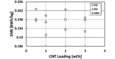
- Example 1 is a photograph of a disk-type segment used in Example 1. It is a schematic diagram of the biaxial kneading extruder which shows the arrangement position of each disk type segment in Example 1 and Comparative Examples 1 and 2. 2 is a photograph of a kneading disc used in Comparative Example 1. 4 is a photograph of a conventional blister disk used in Comparative Example 2. In Example 1 and Comparative Examples 1 and 2, it is a graph which shows the relationship between the addition rate of CNT, and specific mechanical energy. In Example 1 and Comparative Examples 1 and 2, it is a graph which shows the relationship between the addition rate of CNT, and resin temperature.
- Example 1 and Comparative Examples 1 and 2 it is a graph which shows the relationship between specific mechanical energy and resin temperature. It is the viscosity data of CNT density
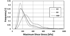
- Example 1 and Comparative Examples 1 and 2 it is a graph which shows the result about the maximum elongation stress in the simulation of an Example.
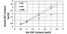
- Example 1 and Comparative Examples 1 and 2 it is a graph which shows the relationship between the setting value of CNT content, and a measured value.
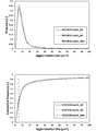
- Example 1 and Comparative Examples 1 and 2 it is a graph which shows the size distribution of the aggregate.
- 4 is a graph showing the ratio of CNT aggregates of 5 ⁇ m 2 or less in Example 1 and Comparative Examples 1 and 2 .
- Example 1 and Comparative Examples 1 and 2 it is a graph which shows the result of a dynamic viscoelasticity measurement.
- Example 1 and Comparative Examples 1 and 2 it is a graph which shows the result of a dynamic viscoelasticity measurement.
- Example 1 and Comparative Examples 1 and 2 it is a graph which shows the result about electroconductivity. In Example 1 and Comparative Examples 1 and 2, it is a graph which shows the result about a crystallinity degree. In Example 1 and Comparative Examples 1 and 2, it is a graph which shows the result about an elasticity modulus. In Example 1 and Comparative Examples 1 and 2, it is a graph which shows the result about tensile strength. 4 is a table summarizing evaluation test results in Example 1 and Comparative Examples 1 and 2.
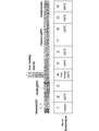
- FIG. FIG. 3 is a schematic view of a twin-screw kneading extruder used in preparing master batches in Examples 2 to 8.
- FIG. 6 is a graph showing measured values of pressure loss with respect to temperature and analytical values by simulation for Examples 2 to 8.
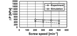
- FIG. 6 is a graph showing measured values of pressure loss with respect to screw rotation speed and analysis values by simulation in Examples 2 to 8.
- 6 is a graph showing measured values of pressure loss with respect to the processing amount and analysis values by simulation in Examples 2 to 8.
- 6 is a graph showing the relationship between the product of viscosity and flow rate and pressure loss for Examples 2 to 8.
- 6 is a graph showing the relationship between pressure loss and SME for Examples 2 to 8.
- 6 is a graph showing the relationship between viscoelastic properties and surface resistivity for Examples 2 to 8.
- 6 is a graph showing the results of a tensile test for Examples 2 to 8.
- 6 is a graph showing the results of morphology observation for Examples 2 to 8.
- 6 is a graph showing the size distribution of aggregates in Examples 2 to 8.
- 6 is a graph showing the ratio of SWCNT aggregates of 20 ⁇ m 2 or less in Examples 2 to 8.
- 6 is a graph showing the relationship between Q / Ns and pressure loss for Examples 2 to 15.
- 6 is a graph showing the relationship between SME and surface resistivity for Examples 2 to 15.
- FIG. 6 is a graph showing the relationship between Q / Ns and pressure loss for Examples 2 to 8 and Examples 16 to 22. 6 is a graph showing the relationship between SME and surface resistivity for Examples 2 to 8 and Examples 16 to 22.
- FIG. 4 is a schematic diagram of a twin-screw kneading extruder showing the arrangement position of each disk-type segment in Examples 23 to 32. 32 is a photograph of a disk-type segment used in Examples 28-32.
- FIG. 9 is a schematic diagram of a twin-screw kneading extruder showing the arrangement position of each disk-type segment in Comparative Examples 3 to 7.
- 6 is a graph showing pressure loss data for Examples 23 to 32 and Comparative Examples 3 to 7.
- 6 is a graph showing discharge temperature data for Examples 23 to 32 and Comparative Examples 3 to 7.
- 6 is a graph showing the relationship between PC dispersion diameter and haze value for Examples 23 to 32 and Comparative Examples 3 to 7.
- 6 is a graph showing measurement results of the droplet diameter of PC for Examples 23 to 32 and Comparative Examples 3 to 7.
- 6 is a graph showing relative haze values (relative values with respect to the haze value of PMMA alone) for Examples 23 to 32 and Comparative Examples 3 to 7.
- a multi-axis kneader according to the present invention a method for producing a nanocomposite using this multi-axis kneader, and preferred embodiments of disk-type segments used in these will be described in detail.
- the scope of the present invention is not limited to these explanations, and modifications other than the following examples can be made as appropriate without departing from the spirit of the present invention.
- the multi-axis kneader according to the present invention is not limited to the extrusion molding machine, and similarly, a kneading mechanism using a plurality of kneading screws.
- twin-screw kneader will be described as an example. However, those skilled in the art can easily apply the present invention to a multi-screw kneader having three or more axes from the technical common sense and the following description. You will get. Furthermore, the various dimensions described below are only examples, and those skilled in the art can easily apply the present invention to various multi-screw kneaders having different scales from the following examples based on common general technical knowledge and the following examples. Can be applied.
- FIG. 1 A twin-screw kneading extruder according to one embodiment of the present invention is shown in FIG.
- the twin-screw kneading extruder 1 has the same basic configuration as that of the prior art, and includes a hollow barrel 11, a hopper 12 for supplying resin into the barrel 11, and resin addition into the barrel 11.
- An additive inlet 13 (side feeder) for supplying the agent and a vent 14 for deaeration and the like are provided.
- a kneading screw 21 is disposed in the barrel 11 along the axial direction. Since the kneading extruder of the present embodiment is biaxial, two kneading screws are paired.
- a disk-type segment 22 is arranged at an intermediate position of the kneading screw 21 and downstream of the additive inlet 13. The “intermediate position” does not necessarily mean the center, but simply means that it is not an entrance or exit position. In this embodiment, only one disk-type segment 22 is provided, but a plurality of disk-type segments 22 may be arranged. In this case, they may be arranged continuously or at intervals. Since the disk-type segment 22 is a segment type, pressure control, its position, number, etc. can be set freely.
- the resin supplied from the hopper 12 is conveyed by the kneading screw 21 while being kneaded in the axial direction from upstream (left side in FIG. 1) to downstream (right side in FIG. 1). At that time, the resin additive is supplied from the additive inlet 13 along the way. From the vent 14, the gas generated during the kneading is discharged.
- the disc-shaped segment 22 has a cross-sectional shape that is substantially the same shape as the inner cross-section of the barrel 11 so as to partition the inside of the barrel 11.
- the disk-type segment 22 has a cross-sectional shape in which two circles are partially overlapped as shown in FIG. 2, and the barrel 11 has a similar inner cross-sectional shape.
- the disc-type segment 22 does not allow the kneaded material to pass through the clearance with the inner wall of the barrel 11 as in a conventional kneading disc, but allows the kneaded material to pass through a small hole 221a (described later). There is no need to provide a gap between the inner wall of the barrel 11. However, a gap may be provided to facilitate the insertion of the disk-type segment 22 into the barrel 11.
- the disk-type segment 22 includes a disk main body 221 and a shaft penetrating portion 222 through which the rotating shaft 21 a of the kneading screw 21 passes rotatably.
- the shaft penetrating part 222 include ball bearings, sleeve bearings, roller bearings, and the like.
- the disk-type segment 22 does not rotate with the rotation of the kneading screw 21 and is in a fixed state at the time of kneading extrusion.
- a large number of small holes 221 a serving as channels for the kneaded material are formed around the shaft penetrating portion 222.
- the disk-type segment in the multi-axis kneader of the present invention is a fixed type that does not rotate with the rotation of the kneading screw, and the kneaded material passes through the small holes very efficiently. . Since two discs are separated and each does not leak between the discs as in the conventional blister disc rotating with the rotation of the kneading screw, a high pressure loss can be brought about.
- this inventor has acquired the knowledge that the dispersibility of a resin additive improves by extending
- the design pressure resistance and dispersibility of the multi-shaft kneader are also taken into consideration for the diameter, axial thickness and number of the small holes 221a, the total opening area of the small holes 221a on the resin flow inlet side, the position, the extrusion speed, and the like. It is desirable to design. For example, although the pressure loss can be increased by increasing the thickness of the small hole, it is desirable that the inside of the small hole be as thin as possible in order to avoid shear heat generation because of the pure shearing action.
- the diameter of the small holes is usually determined in consideration of the size of the resin additive nanoparticles. A preferable range from such a viewpoint will be described below as an example. That is, for example, the diameter of the small hole 221a is set to 0.5 to 1.5 mm, and the thickness of the small hole 221a in the axial direction is 1/12 to the ratio (L / D) of the thickness (L) to the screw diameter (D).
- the number of small holes 221a can be 2 to 64.
- the total opening area of the small holes 221a on the resin flow inlet side can be 4 to 20% of the inner cross-sectional area of the barrel 11, for example. It is preferably within 20%, more preferably within 10%.
- 30 small holes 221a are arranged in a line in a concentric manner with respect to each shaft penetrating portion 222. Unlike this, two or more rows of small holes may be arranged. Further, a small hole is not formed between the shaft penetrating part 222 and the shaft penetrating part 222. However, the present invention is not limited to this, and a small hole is formed between the shaft penetrating part 222 and the shaft penetrating part 222. May be. Further, in the above-described embodiment, the additive inlet 13 is provided in the middle of the barrel 11 and the resin additive is supplied therefrom, but unlike this, the resin and the resin additive are simultaneously supplied from the hopper 12. It is also good.
- the said embodiment knead
- this invention is not limited to this, Kneading
- it can be applied to kneading of a polymer blend (alloy).
- the polymer blend includes a compatible system and an incompatible system, and the degree of compatibility in the compatible system varies, but the present invention is applicable to any of them. More details are as follows.
- ⁇ m matrix phase viscosity
- ⁇ d disperse phase viscosity
- v interfacial tension
- d initial droplet diameter
- the present invention which is excellent in elongation fluidity and can suppress shearing heat generation is suitable for polymer blends, particularly polymer blends having LCST type phase diagrams.
- a preferable polymer blend for example, a polymer blend of polymethyl methacrylate (matrix) and polycarbonate (dispersed phase) can be mentioned.
- This polymer blend utilizes the high rigidity and transparency of polymethyl methacrylate and the high impact and heat resistance of polycarbonate, and exhibits high heat resistance while maintaining transparency and mechanical properties.
- This polymer blend has an LCST type phase diagram, and the LCST is about 285 ° C.
- a plurality of disk-type segments in the multi-axis kneader of the present invention may be arranged, and the positions thereof can be freely set.
- the vacuum pump if there is only one disk-type segment, the vacuum pump is disposed at position A as shown in FIG.
- a plurality of disk-type segments are used, as shown in FIG. 7, not only the position of B1 but also the position of B2 (behind the disk-type segment), a vacuum pump is disposed and devolatilized. Can do. Since the arrangement of the disk-type segments can be freely set, the devolatilization position can be freely changed.
- the method for producing a nanocomposite of the present invention includes a step of adding nanoparticles as a resin additive using the multiaxial kneader of the present invention as described above. Since the multi-axis kneader of the present invention is excellent in nanodispersibility, it is particularly suitable for such a method for producing a nanocomposite.
- the resin is not particularly limited, and examples thereof include general thermoplastic resins such as general-purpose plastics (such as polypropylene), general-purpose engineering plastics, and super-engineering plastics.
- the nanoparticles are not particularly limited, and examples thereof include carbon nanotubes, carbon nanofibers, cellulose nanofibers, graphene, nanoclays, and carbon black.
- the multi-axis kneader according to the present invention the method for producing a nanocomposite using this multi-axis kneader, and the disk-type segments used in these will be described with reference to examples, but the present invention is limited to these examples. Is not to be done.
- Example 1 Using a twin-screw kneading extruder “ZSK18 MEGALab” (manufactured by Coperion, screw diameter 18 mm, L / D: 40), a disk-type segment (hereinafter referred to as “XBD” (hereinafter, “Fixed Blistering Disk”) shown in FIG. ) And a kneading extrusion.
- XBD disk-type segment
- Fixed Blistering Disk a disk-type segment
- FIG. 8 the number of small holes in the XBD is 30.
- the diameter of the small hole is 1 mm
- the axial width (thickness) of the small hole is 3 mm (the axial width of the disk including other portions is 7 mm).
- polypropylene “Prime Polypro (registered trademark) J108M” (manufactured by Prime Polymer Co., Ltd., homopolymer, MFR: 45 g / 10 min (230 ° C.)) is used as a resin, and a resin additive (nanofiller) ) Carbon nanotubes (CNT) “NC7000” (manufactured by NANOCYL, Inc., multi-walled carbon nanotubes, average diameter 9.5 nm, average length 1.5 ⁇ m, aspect ratio 160) were used.
- the arrangement position of XBD in the biaxial kneading extruder was as shown in FIG.
- the kneading and extrusion conditions were a barrel temperature of 200 ° C., a screw rotation speed of 250 rpm, and an input amount of 5.4 kg / h.
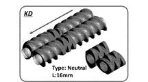
- Kneading extrusion was performed in the same manner as in Example 1 except that a kneading disk (hereinafter abbreviated as “KD”) shown in FIG. 10 was used instead of XBD. As shown in FIG. 10, five discs shifted by 90 ° are continuously formed, and the width (thickness) in the axial direction is 16 mm as a whole. In addition, the arrangement position of KD in the twin-screw kneading extruder is also shown in FIG.
- KD kneading disk
- BD blistering Disk
- the diameter of the small hole is 1 mm
- the axial width (thickness) of the small hole is 3 mm (the axial width of the disk including other portions is 9 mm).
- the arrangement position of the BD in the twin-screw kneading extruder is also shown in FIG.
- Example 1 and Comparative Examples 1 and 2 were evaluated. The results are shown below.
- the results of Example 1 and Comparative Examples 1 and 2 are shown in FIG. 12, with the addition rate (% by weight) of CNTs as the horizontal axis and the specific mechanical energy (SME: Specific Mechanical Energy) (kWh / kg) as the vertical axis.
- SME Specific Mechanical Energy
- the results of Example 1 and Comparative Examples 1 and 2 are shown in FIG. 13 with the addition rate (% by weight) of CNT as the horizontal axis and the resin temperature (° C.) as the vertical axis.
- FIG. 14 shows the results of Example 1 and Comparative Examples 1 and 2, with SME (kWh / kg) as the horizontal axis and the resin temperature (° C.) as the vertical axis.
- Example 1 using XBD SME was the highest.
- FIG. 13 in Example 1 using XBD and Comparative Example 2 using BD, the increase in the resin temperature is suppressed and shearing heat generation is suppressed compared to Comparative Example 1 using KD. I found out.
- the heat generation temperature is lower than the applied energy. This can be understood as an effect of elongational flow.
- the fluid is incompressible and non-Newtonian. Inertia and gravity are negligible. The fluid adheres to the barrel surface. The flow is constant temperature.
- Shear viscosity and elongational viscosity are each defined by the following equations. These are based on the shear viscosity curve and elongational viscosity curve shown in FIG. 15 for a carbon nanotube concentration of 1.0% by weight.
- Shear stress and elongation stress are defined by the following formulas.
- Optical microscope and scanning electron microscope (SEM) Dispersibility was locally evaluated by an optical microscope and a scanning electron microscope (SEM).
- a sample thickness 20 ⁇ m
- a sample was prepared with a microtome “RM2265” (manufactured by Leica), and a cross section was observed with a digital microscope “VHX-5000” (manufactured by Keyence) (magnification 200 ⁇ ).
- the area of the aggregate (1 ⁇ m 2 or more) was measured by image analysis software “SigmaScan Pro5” (manufactured by Hulinks).
- Example 1 For Example 1 (XBD), Comparative Example 1 (KD), and Comparative Example 2 (BD), the relationship between the set value of the CNT content and the measured value is shown in Table 1 and FIG.
- FIG. 24 shows the size distribution of the aggregates when the CNT content (set value) is 0.5% by weight. From this result, it was found that Example 1 (XBD) had a better CNT dispersion state than Comparative Example 1 (KD).
- Example 1 Example 1 (XBD)> Comparative example 2 (BD)> Comparative example 1 (KD) It can be said.
- Example 1 it was found that the dispersibility was improved by about 8% compared to Comparative Example 1, and it was found that the dispersion state was particularly good at a low concentration.
- Conductivity test CNT dispersion was evaluated over the entire area by measuring volume resistivity (based on JIS K7194). For this measurement, a resistivity meter “HIRESTA UP” (manufactured by Mitsubishi Chemical Analytech Co., Ltd.) was used.
- Example 1 (XBD) was lower than that of Comparative Example 1 (KD).
- the CNT network is almost proportional to the dispersion state (Takahiro Takahashi, Ken Yasuda, Takahiro Okubo, Hiroshi Kanno, Koichiro Yonetake, “Composite function of carbon nanotube and polymer”, Carbon TANSO Vol.2006 (2006) No.223 P194-205), it can be said that the smaller the volume resistivity value, the more the dispersion is promoted. Therefore, Dispersion state: Example 1 (XBD)> Comparative example 1 (KD)> Comparative example 2 (BD) It can be said.
- Tensile test JIS K7161 1A test piece was produced using an injection molding machine “PLASTR ET-40V” (manufactured by Toyo Kikai Metal Co., Ltd.). According to JIS K7161, five measurements were performed and the elastic modulus and tensile strength were measured.
- Example 1 XBD
- Comparative Example 2 BD
- Comparative Example 1 KD It can be said. It can be understood that the above results are because the thermal degradation of the polypropylene itself is suppressed and the crystallinity is improved as the dispersibility is improved. In particular, the effect of improving the mechanical strength was high on the low concentration side.
- the multi-axis kneader of the present invention the method for producing a nanocomposite using this multi-axis kneader, and the disk-type segment used therein can avoid resin leakage between disks as in Comparative Example 2, while suppressing shearing. It can be said that it specializes in elongational flow (while suppressing shearing heat generation).
- Example 2 to 8 Using a twin-screw kneading extruder “ZSK18 MEGALab” (manufactured by Coperion, screw diameter 18 mm, L / D: 40), a disk-type segment was placed in the barrel and kneading extrusion was performed. Details are as follows.
- cycloolefin polymer “ZEONOR (registered trademark) 1420R” (manufactured by Nippon Zeon Co., Ltd., amorphous resin, glass transition point 136 ° C., melt flow rate 20 g / 10 min (280 ° C.)) is used as the resin.
- a resin additive nanonanofiller
- single-walled carbon nanotube SWCNT
- ZEONANO registered trademark
- COP was supplied from the hopper, SWCNT was added from the additive inlet, and kneading extrusion was performed to prepare a master batch.
- Melting (KD) is a kneading disk (shown in FIG. 10) used for melting.
- COP was added to the master batch to adjust the concentration so that SWCNT was 0.5 wt%.
- the screw is a full flight screw (FF), and the screw pitch (interval indicated by a in FIG. 35) is 12 mm.
- “Melting (KD)” is a kneading disk (shown in FIG. 10) used for melting.
- the XBD is shown in FIG. 8.
- the number of small holes in the XBD is 30, the diameter of the small holes is 1 mm, and the axial width (thickness) of the small holes is 3 mm (the axial direction of the disk including other parts) Is 7 mm).
- the kneading extrusion conditions in the above operation are as shown in the table below.
- v velocity vector
- ⁇ relative compression factor
- ⁇ shear viscosity
- H step function
- ⁇ a inertia term
- T Surplus stress tensor
- D Deformation rate tensor.
- Optical microscope and scanning electron microscope (SEM) Dispersibility was locally evaluated by an optical microscope and a scanning electron microscope (SEM).
- a sample (thickness 2 ⁇ m) was prepared with a microtome (manufactured by Japan Microtome Research Co., Ltd., RMD-5 type), and the cross section was observed with an optical microscope (manufactured by MEIJI TECHNO, MT9400) (magnification 230 times).
- SEM observation was performed by observing a cross section of the tensile test piece at an acceleration voltage of 10.0 kV using a scanning electron microscope FE-SEM (manufactured by JEOL, JSM-7001FD).
- the area of the aggregate (1 ⁇ m 2 or more) was measured by image analysis software “SigmaScan Pro5” (manufactured by Hulinks).
- Tensile test JIS K7161 1A test piece was produced using an injection molding machine “PLASTR ET-40V” (manufactured by Toyo Kikai Metal Co., Ltd.). In accordance with JIS K7161, seven measurements were made and the elastic modulus, tensile strength and elongation at break were measured.
- the Power-law law is expressed by the following formula.
- K Viscosity coefficient
- Q Flow rate
- n Power-law index
- N Number of through-holes
- R Through-hole radius
- L Through-hole length
- changing the barrel temperature and the rotational speed which are kneading conditions, is synonymous with changing the viscosity from the temperature dependence and shear rate dependence of the viscosity.
- changing the processing amount is synonymous with changing the flow rate.
- ⁇ Shear rate / Elongation rate at disc type segment through hole> 40 to 42 show the analysis results of the shear rate and the stretch rate at the disk-type segment through-holes based on the simulation of COP / SWCNT kneading extrusion. From the results shown in the figure, the barrel temperature (resin temperature) does not affect the strain rate (however, the stress increases), the screw rotational speed decreases with increasing strain rate, and the flow rate increases with increasing strain. It turns out that the speed increases. This tendency is similar to the pressure loss (the pressure loss and the acting stress are equivalent).
- FIG. 44 shows the relationship between viscoelastic properties and surface resistivity for Examples 2 to 8. From the results shown in the figure, it was found that G ′ increased with an increase in SME (decrease in Q / Ns), and the surface resistivity decreased (conductivity improved). That is, SWCNT entanglement depends on SME.
- the pressure loss ( ⁇ p) occurring in the disk-type segment of the present invention is proportional to the product of viscosity and flow rate, and increases with increasing Q / Ns.
- the viscosity and flow rate can be changed by changing the kneading conditions.
- the tensile strength is greatly improved as ⁇ p increases.
- the conductivity improves with increasing SME. From this fact, it was found that ⁇ p promotes macro uniform dispersion of the dispersion material, whereas SME promotes micro dispersion. Although SME and ⁇ p are in a reciprocal relationship, it is difficult to achieve both of them. However, reducing the number of small holes from 30 to 8 results in an increase in pressure loss. It was found that ⁇ p can be improved. On the other hand, it has been found that reducing the screw pitch is not very effective in improving ⁇ p.
- Examples 23 to 27 Using a twin-screw kneading extruder “ZSK18 MEGALab” (manufactured by Coperion, screw diameter 18 mm, L / D: 40), the disk type segment (XBD) shown in FIG. went. As shown in FIG. 8, the number of small holes in the XBD is 30. The diameter of the small hole is 1 mm, and the axial width (thickness) of the small hole is 3 mm (the axial width of the disk including other portions is 7 mm). Polymethyl methacrylate (PMMA) (manufactured by Mitsubishi Chemical Corporation, VH001) was used as the matrix of the polymer blend.
- PMMA Polymethyl methacrylate
- the density is 1.19 g / cm 3 and the melt flow rate (MFR) is 2.0 g / 10 min (230 ° C., 3.73 N). Further, polycarbonate (PC) (manufactured by Mitsubishi Engineering Plastics Co., Ltd., H-4000) was used as the dispersed phase. The density is 1.20 g / cm 3 and the MFR is 63 g / 10 min (300 ° C., 1.20 kgf). PMMA and PC were dry blended at a ratio of PC of 4% by weight, and this was supplied from a hopper to a twin-screw kneading extruder to perform kneading extrusion.
- ⁇ PC dispersion diameter in PMMA> The results of TEM observation are shown in FIG.
- the droplet diameter d pc [nm] is an average value of about 300. From the results shown in the figure, it was found that the dispersion diameter of PC tends to decrease as Q / Ns increases.
- FIG. 60 shows the relationship between the PC dispersion diameter and the haze value for Examples 23 to 32 and Comparative Examples 3 to 7. Moreover, the relative haze value (relative value to the haze value of PMMA alone) is shown in FIG. From the results shown in the figure, it was found that using XBD had a smaller PC droplet diameter and, as a result, a smaller haze value (higher transparency) than using KD.
- the disk-type segment of the present invention can provide a high pressure loss while suppressing shearing heat generation, thereby enabling a process for improving heat resistance while maintaining transparency. That is, it has been found that the disk-type segment of the present invention is extremely effective in application to a polymer blend.
Landscapes
- Engineering & Computer Science (AREA)
- Mechanical Engineering (AREA)
- Manufacturing & Machinery (AREA)
- Processing And Handling Of Plastics And Other Materials For Molding In General (AREA)
- Processes Of Treating Macromolecular Substances (AREA)
- Extrusion Moulding Of Plastics Or The Like (AREA)
Abstract
小孔を有するディスク型セグメントにおける小孔前後にて作用する伸長流動作用を十分に発揮させることのできる多軸混練機及びこの多軸混練機を用いたナノコンポジットの製造方法並びにこれらに用いるディスク型セグメントを提供する。 本発明の多軸混練機は、バレル内に複数の混練スクリュとディスク型セグメントを備え、ディスク型セグメントが、混練材料の投入部より下流でバレル内を仕切るとともに、各混練スクリュの回転軸が回転自在に貫通する複数の軸貫通部と、これらの軸貫通部の周囲に穿設され、混練材料の流路となる多数の小孔を備えている。本発明のナノコンポジットの製造方法は、前記多軸混練機を用いて樹脂添加剤としてナノ粒子を投入する工程を含む。本発明のディスク型セグメントは、前記軸貫通部と前記多数の小孔を備える。
Description
本発明は、多軸混練機及びこの多軸混練機を用いたナノコンポジットの製造方法並びにこれらに用いるディスク型セグメントに関する。
多軸混練機は、
(1)ホモジナイジング:重合反応後のポリマーの不均質構造の解消・添加剤の混合・分散、
(2)ポリマーの可塑化・溶融:ポリマーを可塑化・溶融し、カレンダ加工ラインなどに供給する、
(3)脱水・脱揮(脱溶媒・脱モノマー):ポリマーの乾燥、重合後のポリマーに含まれるモノマー・溶媒の脱揮、
(4)化学反応:ポリマーの重合・解重合・グラフト化などの化学反応を行う、
(5)ポリマーブレンド・アロイ:異種ポリマー、コンパチビライザーの混合・分散、
(6)繊維強化剤・無機質充填材のミクロ混合:繊維強化材の混合・無機質充てん材の混合・凝集塊のミクロサイズ粒子の分散、
(7)カーボンナノチューブなどの繊維強化材・無機質充填材のナノ混合(樹脂中にナノオーダーレベルにて均一に分散させることをいう。以下、同様。):繊維強化材の混合・無機質充てん材の混合・凝集塊のナノサイズ粒子の分散
など、混練目的の違いに応じ、スクリュ形状やその配置・形態等に関して、種々の発展を遂げてきた(非特許文献1の3頁表2等参照。)。
(1)ホモジナイジング:重合反応後のポリマーの不均質構造の解消・添加剤の混合・分散、
(2)ポリマーの可塑化・溶融:ポリマーを可塑化・溶融し、カレンダ加工ラインなどに供給する、
(3)脱水・脱揮(脱溶媒・脱モノマー):ポリマーの乾燥、重合後のポリマーに含まれるモノマー・溶媒の脱揮、
(4)化学反応:ポリマーの重合・解重合・グラフト化などの化学反応を行う、
(5)ポリマーブレンド・アロイ:異種ポリマー、コンパチビライザーの混合・分散、
(6)繊維強化剤・無機質充填材のミクロ混合:繊維強化材の混合・無機質充てん材の混合・凝集塊のミクロサイズ粒子の分散、
(7)カーボンナノチューブなどの繊維強化材・無機質充填材のナノ混合(樹脂中にナノオーダーレベルにて均一に分散させることをいう。以下、同様。):繊維強化材の混合・無機質充てん材の混合・凝集塊のナノサイズ粒子の分散
など、混練目的の違いに応じ、スクリュ形状やその配置・形態等に関して、種々の発展を遂げてきた(非特許文献1の3頁表2等参照。)。
ニーディングディスクは、多軸混練機による混練の基本技術の1つである。
ニーディングディスクは、断面楕円状の板状部材であって、軸方向に複数連続して配置される。ニーディングディスクは混練スクリュの回転に伴って回転し、混練材料は、前記ニーディングディスクとバレル内壁との間に導かれ、混練される(例えば、特許文献1等参照。)。
ニーディングディスクは、断面楕円状の板状部材であって、軸方向に複数連続して配置される。ニーディングディスクは混練スクリュの回転に伴って回転し、混練材料は、前記ニーディングディスクとバレル内壁との間に導かれ、混練される(例えば、特許文献1等参照。)。
ニーディングディスクのねじれ角度が大きくなると、分配・分散の効果は高まる。他方、ねじれ角度が小さくなると、分配・分散効果が低下し、搬送効果が増加する。
また、ディスク厚さが広がるとチップ部でのせん断応力が大きくなり分散効果が高まる。他方、ディスク厚さが小さいと分配効果は高まるが分散効果は低下する。
このように、ディスクのねじれ角度と厚さを変化させることによって分配と分散能力を変えることが可能となる。
また、ディスク厚さが広がるとチップ部でのせん断応力が大きくなり分散効果が高まる。他方、ディスク厚さが小さいと分配効果は高まるが分散効果は低下する。
このように、ディスクのねじれ角度と厚さを変化させることによって分配と分散能力を変えることが可能となる。
しかし、上述したように混練目的が多岐にわたる中で、特に、上記混練目的のうちの(7)カーボンナノチューブなどの繊維強化材・無機質充填材のナノ混合については、ニーディングディスクの制御だけでは限界がある。
ここで、ニーディングディスクを用いた多軸混練機では、せん断流動が支配的であるが、ナノ粒子の分散にはせん断流動よりも伸長流動のほうが効果的であると考えられている。
なお、せん断流動は速度勾配によって材料が引きちぎられる流れであり、伸長流動は、主応力方向に材料が引き伸ばされる流れである。
なお、せん断流動は速度勾配によって材料が引きちぎられる流れであり、伸長流動は、主応力方向に材料が引き伸ばされる流れである。
そこで、ナノ混合という新たなニーズを満たすため、より高い伸長流動を実現するべく、ニーディングディスクに代え、ブリスターディスクが提案されている(例えば、非特許文献1参照。)。このブリスターディスクは、小孔を有しており、この小孔に混練材料を通過させることにより、伸長流動作用を発揮させようというものである。
田中達也、「二軸混練押出機による混練技術/装置の変遷およびナノフィラー分散技術の応用」、バンドーテクニカルレポート、バンドー化学株式会社、第2~8頁、2014年
しかし、従来のブリスターディスクでは、伸長流動の効果が十分に発揮されていないことが判明した。
そこで、本発明は、小孔を有するディスク型セグメントにおける小孔前後にて作用する伸長流動作用を十分に発揮させることのできる多軸混練機及びこの多軸混練機を用いたナノコンポジットの製造方法並びにこれらに用いるディスク型セグメントを提供することを目的としている。
そこで、本発明は、小孔を有するディスク型セグメントにおける小孔前後にて作用する伸長流動作用を十分に発揮させることのできる多軸混練機及びこの多軸混練機を用いたナノコンポジットの製造方法並びにこれらに用いるディスク型セグメントを提供することを目的としている。
伸長流動は小孔入口部で発生する大きな流速変化及びそれに伴う大きな変化勾配の圧力損失によって生じることが知られている。このことも踏まえて、上記課題を解決するため、本発明者は鋭意検討した。その過程において、小孔部で発生する圧力損失を向上させることで、ナノ粒子の分散を向上させることが可能であるとの知見を得た(後述の図3参照。)。そして、従来のブリスターディスクではディスク間での漏れが生じるために圧力損失が低下しており、これにより伸長流動作用が阻害されていることが分かった。
そこで、ディスク間での漏れを解消し、圧力損失の低下を抑制して、伸長流動作用を十分に発揮させるための構成についてさらに種々検討した結果、下記構成を見出したものである。
そこで、ディスク間での漏れを解消し、圧力損失の低下を抑制して、伸長流動作用を十分に発揮させるための構成についてさらに種々検討した結果、下記構成を見出したものである。
すなわち、本発明にかかる多軸混練機は、バレル内に、混練材料を混練するための複数の混練スクリュと、前記混練材料の伸長流動を促進するためのディスク型セグメントを備える多軸混練機であって、前記ディスク型セグメントは、前記混練材料の投入部より下流で前記バレル内を仕切った状態に配置されるとともに、各混練スクリュの回転軸が回転自在に貫通する複数の軸貫通部と、これらの軸貫通部の周囲に穿設され、混練材料の流路となる多数の小孔を備えていることを特徴とする。
本発明にかかるナノコンポジットの製造方法は、上記本発明にかかる多軸混練機を用いて、樹脂添加剤としてナノ粒子を投入する工程を含むことを特徴とする。
また、本発明にかかるディスク型セグメントは、混練材料を混練するための複数の混練スクリュをバレル内に備える多軸混練機に用いられるディスク型セグメントであって、前記バレル内を仕切るとともに、各混練スクリュの回転軸が回転自在に貫通する複数の軸貫通部と、これらの軸貫通部の周囲に穿設され、混練材料の流路となる多数の小孔を備えていることを特徴とする。
なお、本明細書において「ナノ粒子」というときは、原則として、粒子径が0.1nm~100nmの粒子を指すものとする。ただし、本発明の効果を害しない程度の誤差の範囲であれば、前記範囲(0.1nm~100nm)から外れたものであっても、「ナノ粒子」の概念に含めることとする。
また、本発明にかかるディスク型セグメントは、混練材料を混練するための複数の混練スクリュをバレル内に備える多軸混練機に用いられるディスク型セグメントであって、前記バレル内を仕切るとともに、各混練スクリュの回転軸が回転自在に貫通する複数の軸貫通部と、これらの軸貫通部の周囲に穿設され、混練材料の流路となる多数の小孔を備えていることを特徴とする。
なお、本明細書において「ナノ粒子」というときは、原則として、粒子径が0.1nm~100nmの粒子を指すものとする。ただし、本発明の効果を害しない程度の誤差の範囲であれば、前記範囲(0.1nm~100nm)から外れたものであっても、「ナノ粒子」の概念に含めることとする。
本発明の多軸混練機は、従来型のブリスターディスクを用いた多軸混練機よりも圧力損失を向上させることができるものであって、小孔を有するディスク型セグメントによる伸長流動作用を十分に発揮させることができる。そのため、特に樹脂と樹脂添加剤とを含む混練材料の混練に適用した場合において、従来より樹脂添加剤の分散性(特にナノ粒子の分散性)に優れ、成形物の機械的強度向上をもたらすことができる。しかも、せん断発熱が少ないという利点もある。
本発明のナノコンポジットの製造方法は、上記利点を有する多軸混練機を用いるので、従来型のブリスターディスクを用いた多軸混練機よりも圧力損失が向上し、伸長作用がより働き、ナノ粒子の分散性が良好で、機械的強度にも優れたナノコンポジットを提供し得る。
本発明のディスク型セグメントは、上記多軸混練機及びナノコンポジットの製造方法における上記利点をもたらす。
本発明のナノコンポジットの製造方法は、上記利点を有する多軸混練機を用いるので、従来型のブリスターディスクを用いた多軸混練機よりも圧力損失が向上し、伸長作用がより働き、ナノ粒子の分散性が良好で、機械的強度にも優れたナノコンポジットを提供し得る。
本発明のディスク型セグメントは、上記多軸混練機及びナノコンポジットの製造方法における上記利点をもたらす。
以下、本発明にかかる多軸混練機及びこの多軸混練機を用いたナノコンポジットの製造方法並びにこれらに用いるディスク型セグメントの好ましい実施形態について詳しく説明する。
ただし、本発明の範囲はこれらの説明に拘束されることはなく、以下の例示以外についても、本発明の趣旨を損なわない範囲で適宜変更実施し得る。
例えば、以下では、本発明を押出成形に適用した例を示すが、本発明にかかる多軸混練機は、押出成形機に限定されるものではなく、これと同様に複数の混練スクリュによる混練機構を備える他の装置であっても良いし、又はそのような装置の一部であってもよい。
また、以下では、二軸の混練機を例に説明するが、当業者であれば、技術常識及び以下の説明から、三軸以上の多軸混練機に本発明を適用することも容易になし得るであろう。
さらに、以下に記載する各種寸法も一例であって、当業者であれば、技術常識及び以下の例示記載から、以下の例示とはスケールの異なる種々の多軸混練機にも本発明を容易に適用し得るであろう。
ただし、本発明の範囲はこれらの説明に拘束されることはなく、以下の例示以外についても、本発明の趣旨を損なわない範囲で適宜変更実施し得る。
例えば、以下では、本発明を押出成形に適用した例を示すが、本発明にかかる多軸混練機は、押出成形機に限定されるものではなく、これと同様に複数の混練スクリュによる混練機構を備える他の装置であっても良いし、又はそのような装置の一部であってもよい。
また、以下では、二軸の混練機を例に説明するが、当業者であれば、技術常識及び以下の説明から、三軸以上の多軸混練機に本発明を適用することも容易になし得るであろう。
さらに、以下に記載する各種寸法も一例であって、当業者であれば、技術常識及び以下の例示記載から、以下の例示とはスケールの異なる種々の多軸混練機にも本発明を容易に適用し得るであろう。
本発明の一実施形態にかかる二軸混練押出機を図1に示す。
図1に示すように、二軸混練押出機1は、基本的構成は従来と同様であり、中空のバレル11と、バレル11内に樹脂を供給するためのホッパー12、バレル11内に樹脂添加剤を供給するための添加剤投入口13(サイドフィーダ)、脱気等のためのベント14を備える。
図1に示すように、二軸混練押出機1は、基本的構成は従来と同様であり、中空のバレル11と、バレル11内に樹脂を供給するためのホッパー12、バレル11内に樹脂添加剤を供給するための添加剤投入口13(サイドフィーダ)、脱気等のためのベント14を備える。
バレル11内には軸方向に沿って混練スクリュ21が配置される。本実施形態の混練押出機は二軸であるから、2条の混練スクリュが対になっている。
混練スクリュ21の中間位置かつ添加剤投入口13の下流側に、ディスク型セグメント22が配置される。なお、「中間位置」とは、必ずしも中央を意味するものではなく、単に入口ないし出口の位置でないことを意味する。また、本実施形態では、ディスク型セグメント22は1枚のみであるが、複数枚配置しても良く、その場合、連続的に配置しても良いし、間隔を空けて配置しても良い。ディスク型セグメント22はセグメントタイプであるため、圧力制御や、その位置、個数等を自由に設定できる。
混練スクリュ21の中間位置かつ添加剤投入口13の下流側に、ディスク型セグメント22が配置される。なお、「中間位置」とは、必ずしも中央を意味するものではなく、単に入口ないし出口の位置でないことを意味する。また、本実施形態では、ディスク型セグメント22は1枚のみであるが、複数枚配置しても良く、その場合、連続的に配置しても良いし、間隔を空けて配置しても良い。ディスク型セグメント22はセグメントタイプであるため、圧力制御や、その位置、個数等を自由に設定できる。
ホッパー12から供給された樹脂は、混練スクリュ21によって、上流(図1左側)から下流(図1右側)へ軸方向に混練されながら搬送される。その際、途中で添加剤投入口13から樹脂添加剤が供給される。ベント14からは、混練中に発生したガスの排出等が行われる。
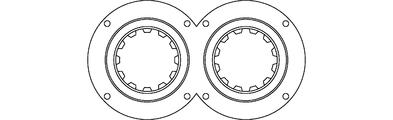
ディスク型セグメント22は、バレル11内を仕切るように、バレル11の内断面と略同形状の断面形状を備える。具体的には、ディスク型セグメント22は、図2に示すように2つの円が一部重ね合わされたような断面形状を有し、バレル11も同様の内断面形状を有する。
ディスク型セグメント22は、従来のニーディングディスクのように、バレル11内壁とのクリアランスに混練材料を通過させるのではなく、その小孔221a(後述する)に混練材料を通過させるものであるので、バレル11内壁との間に隙間を設ける必要はない。
ただし、ディスク型セグメント22をバレル11内に挿入する作業上、これを容易ならしめる程度の隙間を設けても良い。
ただし、ディスク型セグメント22をバレル11内に挿入する作業上、これを容易ならしめる程度の隙間を設けても良い。
図2に示すように、ディスク型セグメント22は、ディスク本体221と、混練スクリュ21の回転軸21aが回転自在に貫通する軸貫通部222を備えている。
軸貫通部222としては、例えば、ボールベアリングやスリーブベアリング、ローラーベアリングなどのベアリングが挙げられる。
ディスク型セグメント22は、混練スクリュ21の回転に伴って回転することなく、混練押出時において、固定された状態となる。
軸貫通部222の周囲には、混練材料の流路となる多数の小孔221aが形成されている。
軸貫通部222としては、例えば、ボールベアリングやスリーブベアリング、ローラーベアリングなどのベアリングが挙げられる。
ディスク型セグメント22は、混練スクリュ21の回転に伴って回転することなく、混練押出時において、固定された状態となる。
軸貫通部222の周囲には、混練材料の流路となる多数の小孔221aが形成されている。
以上の説明から明らかなとおり、本発明の多軸混練機におけるディスク型セグメントは、混練スクリュの回転に伴って回転することのない固定式であり、極めて効率的に混練材料が小孔を通過する。ディスク2枚が分離し、各々が混練スクリュの回転に伴って回転する従来型のブリスターディスクのように、ディスク間での漏れも生じないことから、高い圧力損失をもたらすことができる。
ここで、本発明者は、大きな圧力損失を与え、小孔を通過させることで、伸長流動により樹脂添加剤の分散性が向上するとの知見を得ている。
このことを示すデータを図3に示す。詳しい実験条件等の記載は省略するが、その要旨は、小孔の孔、個数、押出速度を変更し、ポリプロピレン中のカーボンナノチューブの分散を測定したものである。
図3より、圧力損失が大きい方が、伸長流動が促進され樹脂添加剤の分散性が高くなっており、この例(樹脂=ポリプロピレン、樹脂添加剤=カーボンナノチューブ)では、圧力損失約1.5~2.0MPaにおいて高い分散性が得られている。
従って、本発明によれば、従来型のブリスターディスクと比べて高い圧力損失を生じさせることが可能である結果、伸長流動の効果を十分に発揮させ、優れた分散性を得ることができる。
ここで、本発明者は、大きな圧力損失を与え、小孔を通過させることで、伸長流動により樹脂添加剤の分散性が向上するとの知見を得ている。
このことを示すデータを図3に示す。詳しい実験条件等の記載は省略するが、その要旨は、小孔の孔、個数、押出速度を変更し、ポリプロピレン中のカーボンナノチューブの分散を測定したものである。
図3より、圧力損失が大きい方が、伸長流動が促進され樹脂添加剤の分散性が高くなっており、この例(樹脂=ポリプロピレン、樹脂添加剤=カーボンナノチューブ)では、圧力損失約1.5~2.0MPaにおいて高い分散性が得られている。
従って、本発明によれば、従来型のブリスターディスクと比べて高い圧力損失を生じさせることが可能である結果、伸長流動の効果を十分に発揮させ、優れた分散性を得ることができる。
上に述べたことから、多軸混練機の設計耐圧を超えないよう留意しつつ、その限度で所望の分散に必要な圧力損失を確保することが好ましい。
従って、小孔221aの径、軸方向の厚み、数、小孔221aの樹脂流れ入口側の開口面積の総計、位置、押出速度などについても、多軸混練機の設計耐圧、分散性を考慮して設計することが望ましい。
例えば、小孔の厚みを持たせることで圧力損失を上げることはできるが、小孔内部は純粋なせん断作用のため、せん断発熱をさけるためには極力薄くすることが望ましい。また、小孔の数は多い方がナノ粒子の分配作用が期待できる。小孔の径について、通常、樹脂添加剤のナノ粒子のサイズを考慮して決定することになる。
このような観点から好ましい範囲を一例として以下に述べる。
すなわち、例えば、小孔221aの径を0.5~1.5mmとし、軸方向の小孔221aの厚みをスクリュ径(D)に対する厚み(L)の比(L/D)で1/12~1/4とし、小孔221aの数を2~64個とすることができる。
また、小孔221aの樹脂流れ入口側の開口面積の総計は、例えば、バレル11の内断面積の4~20%とすることができる。20%以内とすることが好ましく、10%以内とすることがより好ましい。
従って、小孔221aの径、軸方向の厚み、数、小孔221aの樹脂流れ入口側の開口面積の総計、位置、押出速度などについても、多軸混練機の設計耐圧、分散性を考慮して設計することが望ましい。
例えば、小孔の厚みを持たせることで圧力損失を上げることはできるが、小孔内部は純粋なせん断作用のため、せん断発熱をさけるためには極力薄くすることが望ましい。また、小孔の数は多い方がナノ粒子の分配作用が期待できる。小孔の径について、通常、樹脂添加剤のナノ粒子のサイズを考慮して決定することになる。
このような観点から好ましい範囲を一例として以下に述べる。
すなわち、例えば、小孔221aの径を0.5~1.5mmとし、軸方向の小孔221aの厚みをスクリュ径(D)に対する厚み(L)の比(L/D)で1/12~1/4とし、小孔221aの数を2~64個とすることができる。
また、小孔221aの樹脂流れ入口側の開口面積の総計は、例えば、バレル11の内断面積の4~20%とすることができる。20%以内とすることが好ましく、10%以内とすることがより好ましい。
なお、本実施形態では、各軸貫通部222の同心円状に一列に、30個の小孔221aが配置されている。これと異なり、小孔を2列以上配置してもよい。
また、軸貫通部222と軸貫通部222との間には小孔を穿設していないが、これに限定されず、軸貫通部222と軸貫通部222との間に小孔を穿設してもよい。
さらに、上記実施形態は、バレル11の途中に添加剤投入口13を設け、そこから樹脂添加剤を投入する構成としたが、これと異なり、ホッパー12から樹脂と樹脂添加剤を同時に投入する構成としても良い。
また、軸貫通部222と軸貫通部222との間には小孔を穿設していないが、これに限定されず、軸貫通部222と軸貫通部222との間に小孔を穿設してもよい。
さらに、上記実施形態は、バレル11の途中に添加剤投入口13を設け、そこから樹脂添加剤を投入する構成としたが、これと異なり、ホッパー12から樹脂と樹脂添加剤を同時に投入する構成としても良い。
また、上記実施形態は、樹脂と樹脂添加剤とを含む混練材料を混練するものであるが、本発明はこれに限定されるものではなく、良好な伸長流動が求められる他の混練材料の混練に適用しても良い。
例えば、ポリマーブレンド(アロイ)の混練にも適用することができる。ポリマーブレンドには相溶系と非相溶系があり、相溶系における相溶性の程度も様々であるが、本発明はいずれにも適用可能である。より詳細には以下のとおりである。
ポリマーブレンドの分散は、以下のパラメータに依存する。
粘度比:λ=ηd/ηm
キャピラリー数:Ca(We)
分散に要する時間:t*
また、液滴分散の条件は下式のとおりである(Talorの式)
例えば、ポリマーブレンド(アロイ)の混練にも適用することができる。ポリマーブレンドには相溶系と非相溶系があり、相溶系における相溶性の程度も様々であるが、本発明はいずれにも適用可能である。より詳細には以下のとおりである。
ポリマーブレンドの分散は、以下のパラメータに依存する。
粘度比:λ=ηd/ηm
キャピラリー数:Ca(We)
分散に要する時間:t*
また、液滴分散の条件は下式のとおりである(Talorの式)

上記において、
ηm:母相粘度
ηd:分散相粘度
v:界面張力
d:初期の液滴径
である。
ηm:母相粘度
ηd:分散相粘度
v:界面張力
d:初期の液滴径
である。
図4に、ポリマーブレンドにおける粘度比とウェーバー数We(キャピラリー数Ca)の関係を示す(H.P.Grace,Chemical Engineering Communications,Vol.14(3-6)(1982),pp.225-277.)。
図4に見るように、せん断流動では粘度比λ>3.8で分散不可だが、伸長流動ではλ>3.8でも分散可能であり、ポリマーブレンド(液-液系)でも伸長流動は有効である。
また、図5に示すポリマーブレンドの相図から分かるように、ポリマーブレンドは温度によって相溶性が決定される(ただし、圧力やせん断によって相図範囲も変化する)。そして、LCST型の相図を持つポリマーブレンドについては、LCST以下の温度で混練することが必要となる。
図4に見るように、せん断流動では粘度比λ>3.8で分散不可だが、伸長流動ではλ>3.8でも分散可能であり、ポリマーブレンド(液-液系)でも伸長流動は有効である。
また、図5に示すポリマーブレンドの相図から分かるように、ポリマーブレンドは温度によって相溶性が決定される(ただし、圧力やせん断によって相図範囲も変化する)。そして、LCST型の相図を持つポリマーブレンドについては、LCST以下の温度で混練することが必要となる。
以上のことから、伸長流動性に優れ、かつ、せん断発熱が抑制可能な本発明は、ポリマーブレンド、特にLCST型の相図を持つポリマーブレンドに好適である。
好ましいポリマーブレンドの一例としては、例えば、ポリメタクリル酸メチル(母相)とポリカーボネート(分散相)のポリマーブレンドを挙げることができる。このポリマーブレンドは、ポリメタクリル酸メチルによる高い剛性と透明性、ポリカーボネートによる高い衝撃性と耐熱性が活かされ、透明性・機械的物性を維持しながら高い耐熱性が発揮される。なお、このポリマーブレンドは、LCST型の相図を持ち、LCSTは約285℃である。
好ましいポリマーブレンドの一例としては、例えば、ポリメタクリル酸メチル(母相)とポリカーボネート(分散相)のポリマーブレンドを挙げることができる。このポリマーブレンドは、ポリメタクリル酸メチルによる高い剛性と透明性、ポリカーボネートによる高い衝撃性と耐熱性が活かされ、透明性・機械的物性を維持しながら高い耐熱性が発揮される。なお、このポリマーブレンドは、LCST型の相図を持ち、LCSTは約285℃である。
また、本発明の多軸混練機におけるディスク型セグメントは、上述したとおり、複数枚配置しても良く、その位置も自由に設定することができる。
真空ポンプにより脱揮する場合において、ディスク型セグメントが一枚であると、図6に示すように、Aの位置に真空ポンプを配置することになる。他方、ディスク型セグメントを複数枚用いるようにすれば、図7に示すように、B1の位置だけでなく、B2の位置(ディスク型セグメントの背後)にも真空ポンプを配置し、脱揮させることができる。ディスク型セグメントの配置が自由に設定できるため、脱揮位置も自由に変更できるという利点を有することになる。
真空ポンプにより脱揮する場合において、ディスク型セグメントが一枚であると、図6に示すように、Aの位置に真空ポンプを配置することになる。他方、ディスク型セグメントを複数枚用いるようにすれば、図7に示すように、B1の位置だけでなく、B2の位置(ディスク型セグメントの背後)にも真空ポンプを配置し、脱揮させることができる。ディスク型セグメントの配置が自由に設定できるため、脱揮位置も自由に変更できるという利点を有することになる。
本発明のナノコンポジットの製造方法は、上述した如き本発明の多軸混練機を用いて、樹脂添加剤としてナノ粒子を添加する工程を含む。
本発明の多軸混練機は、ナノ分散性に優れるので、このようなナノコンポジットの製造方法に特に好適である。
この場合、樹脂としては、特に限定するわけではないが、一般的な熱可塑性樹脂、例えば、汎用プラスチック(ポリプロピレン等)、汎用エンジニアリングプラスチック、スーパーエンジニアリングプラスチックなどが挙げられる。
また、ナノ粒子としては、特に限定するわけではないが、例えば、カーボンナノチューブ、カーボンナノファイバ、セルロースナノファイバ、グラフェン、ナノクレイ、カーボンブラックなどが挙げられる。
本発明の多軸混練機は、ナノ分散性に優れるので、このようなナノコンポジットの製造方法に特に好適である。
この場合、樹脂としては、特に限定するわけではないが、一般的な熱可塑性樹脂、例えば、汎用プラスチック(ポリプロピレン等)、汎用エンジニアリングプラスチック、スーパーエンジニアリングプラスチックなどが挙げられる。
また、ナノ粒子としては、特に限定するわけではないが、例えば、カーボンナノチューブ、カーボンナノファイバ、セルロースナノファイバ、グラフェン、ナノクレイ、カーボンブラックなどが挙げられる。
以下、実施例を用いて、本発明にかかる多軸混練機及びこの多軸混練機を用いたナノコンポジットの製造方法並びにこれらに用いるディスク型セグメントについて説明するが、本発明はこれら実施例に限定されるものではない。
〔実施例1〕
二軸混練押出機「ZSK18 MEGAlab」(Coperion社製。スクリュ径18mm、L/D:40)を用いて、そのバレル内に、図8に示すディスク型セグメント(以下、「XBD」(Fixed Blistering Disk)と略記する)を配置し、混練押出を行った。
図8に示すとおり、XBDの小孔の数は30個である。また、小孔の径は1mmであり、小孔の軸方向の幅(厚み)は3mm(他の部分も含めたディスクの軸方向の幅は7mm)である。
混練材料としては、樹脂としてポリプロピレン(PP)「プライムポリプロ(登録商標) J108M」(株式会社プライムポリマー社製。ホモポリマー、MFR:45g/10min(230℃))を用い、樹脂添加剤(ナノフィラー)としてカーボンナノチューブ(CNT)「NC7000」(NANOCYL社製。多層カーボンナノチューブ、平均径9.5nm、平均長さ1.5μm、アスペクト比160)を用いた。
二軸混練押出機におけるXBDの配置位置は図9に示すとおりとした。
また、混練押出条件は、バレル温度200℃、スクリュ回転数250rpm、投入量5.4kg/hとした。
二軸混練押出機「ZSK18 MEGAlab」(Coperion社製。スクリュ径18mm、L/D:40)を用いて、そのバレル内に、図8に示すディスク型セグメント(以下、「XBD」(Fixed Blistering Disk)と略記する)を配置し、混練押出を行った。
図8に示すとおり、XBDの小孔の数は30個である。また、小孔の径は1mmであり、小孔の軸方向の幅(厚み)は3mm(他の部分も含めたディスクの軸方向の幅は7mm)である。
混練材料としては、樹脂としてポリプロピレン(PP)「プライムポリプロ(登録商標) J108M」(株式会社プライムポリマー社製。ホモポリマー、MFR:45g/10min(230℃))を用い、樹脂添加剤(ナノフィラー)としてカーボンナノチューブ(CNT)「NC7000」(NANOCYL社製。多層カーボンナノチューブ、平均径9.5nm、平均長さ1.5μm、アスペクト比160)を用いた。
二軸混練押出機におけるXBDの配置位置は図9に示すとおりとした。
また、混練押出条件は、バレル温度200℃、スクリュ回転数250rpm、投入量5.4kg/hとした。
〔比較例1〕
XBDに代えて、図10に示すニーディングディスク(Kneading Disk。以下、「KD」と略記する。)を用いたこと以外は、実施例1と同様にして、混練押出を行った。
図10に示すとおり、90°ずらした5枚のディスクが連続して構成され、これらの軸方向の幅(厚み)は全体で16mmである。
なお、二軸混練押出機におけるKDの配置位置は図9に併せて示している。
XBDに代えて、図10に示すニーディングディスク(Kneading Disk。以下、「KD」と略記する。)を用いたこと以外は、実施例1と同様にして、混練押出を行った。
図10に示すとおり、90°ずらした5枚のディスクが連続して構成され、これらの軸方向の幅(厚み)は全体で16mmである。
なお、二軸混練押出機におけるKDの配置位置は図9に併せて示している。
〔比較例2〕
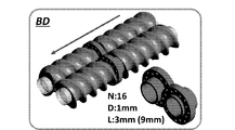
XBDに代えて、図11に示す従来型のブリスターディスク(Blistering Disk。以下、「BD」と略記する。)を用いたこと以外は、実施例1と同様にして、混練押出を行った。
図11に示すとおり、BDの小孔の数は32(=16×2)個である。また、小孔の径は1mmであり、小孔の軸方向の幅(厚み)は3mm(他の部分も含めたディスクの軸方向の幅は9mm)である。
なお、二軸混練押出機におけるBDの配置位置は図9に併せて示している。
XBDに代えて、図11に示す従来型のブリスターディスク(Blistering Disk。以下、「BD」と略記する。)を用いたこと以外は、実施例1と同様にして、混練押出を行った。
図11に示すとおり、BDの小孔の数は32(=16×2)個である。また、小孔の径は1mmであり、小孔の軸方向の幅(厚み)は3mm(他の部分も含めたディスクの軸方向の幅は9mm)である。
なお、二軸混練押出機におけるBDの配置位置は図9に併せて示している。
〔混練特性評価1〕
実施例1、比較例1及び2における混練特性の評価を行った。結果を以下に示す。
CNTの添加率(重量%)を横軸、比機械的エネルギー(SME:Specific Mechanical Energy)(kWh/kg)を縦軸とし、実施例1、比較例1,2の結果を図12に示す。
CNTの添加率(重量%)を横軸、樹脂温度(℃)を縦軸とし、実施例1、比較例1,2の結果を図13に示す。
SME(kWh/kg)を横軸、樹脂温度(℃)を縦軸とし、実施例1、比較例1,2の結果を図14に示す。
実施例1、比較例1及び2における混練特性の評価を行った。結果を以下に示す。
CNTの添加率(重量%)を横軸、比機械的エネルギー(SME:Specific Mechanical Energy)(kWh/kg)を縦軸とし、実施例1、比較例1,2の結果を図12に示す。
CNTの添加率(重量%)を横軸、樹脂温度(℃)を縦軸とし、実施例1、比較例1,2の結果を図13に示す。
SME(kWh/kg)を横軸、樹脂温度(℃)を縦軸とし、実施例1、比較例1,2の結果を図14に示す。
図12に示すとおり、XBDを用いた実施例1において、SMEが最も高かった。
他方、図13から、XBDを用いた実施例1やBDを用いた比較例2では、KDを用いた比較例1と比べて、樹脂温度の上昇が抑制されており、せん断発熱が抑制されていることが分かった。
図12~14の結果から分かるように、XBDを用いた実施例1では、与えたエネルギーに対して、発熱温度が低い。これは伸長流動の効果であると理解できる。
他方、図13から、XBDを用いた実施例1やBDを用いた比較例2では、KDを用いた比較例1と比べて、樹脂温度の上昇が抑制されており、せん断発熱が抑制されていることが分かった。
図12~14の結果から分かるように、XBDを用いた実施例1では、与えたエネルギーに対して、発熱温度が低い。これは伸長流動の効果であると理解できる。
〔混練特性評価2〕
混練特性をさらに明らかにするため、以下のとおり、シミュレーションを行った。
シミュレーションには、粘性・粘弾性有限要素解析ソフトウェア「ANSYSPOLYFLOW16.0」を使用した。
混練特性をさらに明らかにするため、以下のとおり、シミュレーションを行った。
シミュレーションには、粘性・粘弾性有限要素解析ソフトウェア「ANSYSPOLYFLOW16.0」を使用した。
<支配方程式>


上記支配方程式において、
v:速度ベクトル
τ:余剰応力テンソル
P:圧力
η:粘度
D:変形速度テンソル
である。
v:速度ベクトル
τ:余剰応力テンソル
P:圧力
η:粘度
D:変形速度テンソル
である。
<前提>
流体は非圧縮性であり、非ニュートン粘性である。
慣性及び重力は無視できる。
流体はバレル表面に付着する。
流動は恒温である。
流体は非圧縮性であり、非ニュートン粘性である。
慣性及び重力は無視できる。
流体はバレル表面に付着する。
流動は恒温である。
<ひずみ速度>
せん断速度は以下で規定される。
せん断速度は以下で規定される。

伸長速度は以下で規定される。

<応力>
せん断粘度及び伸長粘度はそれぞれ下式で規定される。これらは、カーボンナノチューブ濃度1.0重量%についての図15に示すせん断粘度カーブ及び伸長粘度カーブに基づく。
せん断粘度及び伸長粘度はそれぞれ下式で規定される。これらは、カーボンナノチューブ濃度1.0重量%についての図15に示すせん断粘度カーブ及び伸長粘度カーブに基づく。


せん断応力及び伸長応力はそれぞれ下式で規定される。


<粒子追跡>
下記解析条件で、粒子2000個を入口から出口まで流し、最大せん断応力、最大伸長応力、滞留時間及び圧力分布について、粒子が受ける各パラメータ値のヒストグラムを作成した。
(解析条件)
流量一定(5.4kg/h)
流路表面で速度ゼロ
流路出口で圧力ゼロ
粘度:PP/CNT(1重量%)200℃
回転数:250rpm
(モデル)
シミュレーションにおけるモデルを図16~図18に示す。
図16に示すモデルは上記実施例1に対応する(XBD)。図17に示すモデルは上記比較例1に対応する(KD)。図18に示すモデルは上記比較例2に対応する(BD)。
下記解析条件で、粒子2000個を入口から出口まで流し、最大せん断応力、最大伸長応力、滞留時間及び圧力分布について、粒子が受ける各パラメータ値のヒストグラムを作成した。
(解析条件)
流量一定(5.4kg/h)
流路表面で速度ゼロ
流路出口で圧力ゼロ
粘度:PP/CNT(1重量%)200℃
回転数:250rpm
(モデル)
シミュレーションにおけるモデルを図16~図18に示す。
図16に示すモデルは上記実施例1に対応する(XBD)。図17に示すモデルは上記比較例1に対応する(KD)。図18に示すモデルは上記比較例2に対応する(BD)。
<シミュレーション結果>
滞留時間についての結果を、図19に示す。
図19に示す結果から、KDと比較し、BD、XBDの滞留時間は短く、XBDの分布はよりシャープであった。
このことから、XBDでは、滞留時間が均一化されており、物性ばらつきの低減化が可能となることが分かった。
滞留時間についての結果を、図19に示す。
図19に示す結果から、KDと比較し、BD、XBDの滞留時間は短く、XBDの分布はよりシャープであった。
このことから、XBDでは、滞留時間が均一化されており、物性ばらつきの低減化が可能となることが分かった。
圧力分布についての結果を、図20に示す。
図20に示す結果から、XBDでは、BDと比較してディスク間での漏洩が減少、圧力損失が上昇することが分かった(40%以上の向上)。なお、CNTの分散に必要な圧力損失値は1.5~2MPaである。
図20に示す結果から、XBDでは、BDと比較してディスク間での漏洩が減少、圧力損失が上昇することが分かった(40%以上の向上)。なお、CNTの分散に必要な圧力損失値は1.5~2MPaである。
最大せん断応力及び最大伸長応力についての結果を、図21,22に示す。
図21に示す結果から、KDと比較し、BD、XBDでは、せん断応力の分布が低応力側へシフトしていることが分かる。
すなわち、
せん断混練効果:KD>XBD>BD
であり、XBD,BDの方が、KDよりもせん断発熱が抑制されることが分かる。
図22に示す結果から、XBDでは、KD,BDと比べて、高伸長応力を発生させることが可能であることがわかった。
すなわち、
伸長混練効果:XBD>BD≧KD
であった。
図21に示す結果から、KDと比較し、BD、XBDでは、せん断応力の分布が低応力側へシフトしていることが分かる。
すなわち、
せん断混練効果:KD>XBD>BD
であり、XBD,BDの方が、KDよりもせん断発熱が抑制されることが分かる。
図22に示す結果から、XBDでは、KD,BDと比べて、高伸長応力を発生させることが可能であることがわかった。
すなわち、
伸長混練効果:XBD>BD≧KD
であった。
〔CNTの分散及びナノコンポジットの物性の各評価〕
上記実施例1、比較例1及び比較例2で得られた各ナノコンポジットについて、下記のとおり、CNTの分散及びナノコンポジットの物性の各評価を行った。
上記実施例1、比較例1及び比較例2で得られた各ナノコンポジットについて、下記のとおり、CNTの分散及びナノコンポジットの物性の各評価を行った。
<CNTの分散状態の評価>
(1)光学顕微鏡及び走査型電子顕微鏡(SEM)
光学顕微鏡及び走査型電子顕微鏡(SEM)により、分散性を局所的に評価した。
ミクロトーム「RM2265」(ライカ社製)により、試料(厚み20μm)を作製し、デジタルマイクロスコープ「VHX-5000」(キーエンス社製)で断面を観察した(倍率200倍)。
画像解析ソフトウェア「SigmaScan Pro5」(ヒューリンクス社製)により、凝集体(1μm2以上)の面積を測定した。
(1)光学顕微鏡及び走査型電子顕微鏡(SEM)
光学顕微鏡及び走査型電子顕微鏡(SEM)により、分散性を局所的に評価した。
ミクロトーム「RM2265」(ライカ社製)により、試料(厚み20μm)を作製し、デジタルマイクロスコープ「VHX-5000」(キーエンス社製)で断面を観察した(倍率200倍)。
画像解析ソフトウェア「SigmaScan Pro5」(ヒューリンクス社製)により、凝集体(1μm2以上)の面積を測定した。
実施例1(XBD)、比較例1(KD)、比較例2(BD)について、CNT含有量の設定値と実測値との関係を下表1及び図23に示す。

これらの結果から、各実施例、比較例間でCNT含有量が異なることが分かる。これはCNTの滞留状態が異なることを示すものと理解される。特に、比較例2(BD)において減少傾向が認められた。
CNT含有量(設定値)0.5重量%における凝集体のサイズの分布を図24に示す。
この結果から、実施例1(XBD)は、比較例1(KD)と比較し、CNTの分散状態が良好であることが分かった。
この結果から、実施例1(XBD)は、比較例1(KD)と比較し、CNTの分散状態が良好であることが分かった。
また、5μm2以下(1μm2以上)のCNT凝集体が占める割合を計算し、その結果を図25にまとめた。
この結果から、
分散状態:実施例1(XBD)>比較例2(BD)>比較例1(KD)
といえる。
実施例1は、比較例1と比較して、およそ8%分散性が向上したことが分かり、特に低濃度において分散状態が良好であることが分かった。
この結果から、
分散状態:実施例1(XBD)>比較例2(BD)>比較例1(KD)
といえる。
実施例1は、比較例1と比較して、およそ8%分散性が向上したことが分かり、特に低濃度において分散状態が良好であることが分かった。
(2)動的粘弾性測定
周波数依存測定(貯蔵弾性率G’,複素粘度|η*|)により、分散(CNTのネットワーク状態)を全域的に評価した。
「HAAKETM MARSTM レオメーター」(サーモフィッシャーサイエンティフィック社製)を用い、下記のとおり、評価した。
・平板/平板:直径20mm、厚み1mm
・周波数依存測定:0.1~350rad/s *線形粘弾性領域(ひずみ10%)
・温度:220℃
周波数依存測定(貯蔵弾性率G’,複素粘度|η*|)により、分散(CNTのネットワーク状態)を全域的に評価した。
「HAAKETM MARSTM レオメーター」(サーモフィッシャーサイエンティフィック社製)を用い、下記のとおり、評価した。
・平板/平板:直径20mm、厚み1mm
・周波数依存測定:0.1~350rad/s *線形粘弾性領域(ひずみ10%)
・温度:220℃
測定結果を図26,27に示す。
0.5重量%付近では、各実施例、比較例間で分散の違いが顕著に見られる。
分散状態:実施例1(XBD)>比較例2(BD)>比較例1(KD)
といえ、光学顕微鏡による観察結果と同様の傾向であった。
0.5重量%付近では、各実施例、比較例間で分散の違いが顕著に見られる。
分散状態:実施例1(XBD)>比較例2(BD)>比較例1(KD)
といえ、光学顕微鏡による観察結果と同様の傾向であった。
(3)導電性試験
体積抵抗率の測定(JIS K7194に準拠)により、CNT分散を全域的に評価した。
この測定には、抵抗率計「ハイレスタUP」(三菱化学アナリテック社製)を用いた。
体積抵抗率の測定(JIS K7194に準拠)により、CNT分散を全域的に評価した。
この測定には、抵抗率計「ハイレスタUP」(三菱化学アナリテック社製)を用いた。
測定結果を図28に示す。
比較例1(KD)と比較し、実施例1(XBD)の方が、体積抵抗率が低いことが分かった。
ここで、CNTのネットワークは、分散状態にほぼ比例する(高橋辰宏、安田健、大久保貴啓、粟野宏、米竹孝一郎著、“カーボンナノチューブと高分子の複合機能化”、炭素TANSO Vol.2006 (2006) No.223 P194-205参照。)から、体積抵抗率の値が小さいほど分散は促進しているといえる。
従って、
分散状態:実施例1(XBD)>比較例1(KD)>比較例2(BD)
といえる。
比較例1(KD)と比較し、実施例1(XBD)の方が、体積抵抗率が低いことが分かった。
ここで、CNTのネットワークは、分散状態にほぼ比例する(高橋辰宏、安田健、大久保貴啓、粟野宏、米竹孝一郎著、“カーボンナノチューブと高分子の複合機能化”、炭素TANSO Vol.2006 (2006) No.223 P194-205参照。)から、体積抵抗率の値が小さいほど分散は促進しているといえる。
従って、
分散状態:実施例1(XBD)>比較例1(KD)>比較例2(BD)
といえる。
<機械的強度の評価>
(4)結晶化度
示差走査熱量測定(DSC)「Q 1000」(TA Instrument社製)を用いて、下記条件で、結晶化度を測定した。
・昇温・降温20℃(K)/min 0℃~200℃範囲
・結晶化度の測定(1st cooling and 2nd heating time)
・窒素雰囲気下
(4)結晶化度
示差走査熱量測定(DSC)「Q 1000」(TA Instrument社製)を用いて、下記条件で、結晶化度を測定した。
・昇温・降温20℃(K)/min 0℃~200℃範囲
・結晶化度の測定(1st cooling and 2nd heating time)
・窒素雰囲気下
測定結果を図29に示す。
なお、Xcは下式で算出される。
なお、Xcは下式で算出される。

上式において、
ΔHm:溶融エンタルピー
ΔHm 0:100%結晶性ポリマーのエンタルピー(※ポリプロピレンのΔHm 0=207.1(J/g))
α:CNT添加率(重量%)
である。
ΔHm:溶融エンタルピー
ΔHm 0:100%結晶性ポリマーのエンタルピー(※ポリプロピレンのΔHm 0=207.1(J/g))
α:CNT添加率(重量%)
である。
CNTによってマトリックスの結晶性が向上することで、機械的強度の向上につながる。
従って、
機械的強度:実施例1(XBD)>比較例2(BD)>比較例1(KD)
といえる。
従って、
機械的強度:実施例1(XBD)>比較例2(BD)>比較例1(KD)
といえる。
(5)引張試験
射出成形機「PLASTR ET-40V」(東洋機械金属社製)を用い、JIS K7161 1A試験片を作製した。
JIS K7161に従い、5本測定を行い、弾性率及び引張強度を測定した。
射出成形機「PLASTR ET-40V」(東洋機械金属社製)を用い、JIS K7161 1A試験片を作製した。
JIS K7161に従い、5本測定を行い、弾性率及び引張強度を測定した。
測定結果を図30,31に示す。
これらの結果から、実施例1(XBD)では、弾性率及び引張強度がともに改善されていることが分かる。
従って、
機械的強度:実施例1(XBD)>比較例2(BD)>比較例1(KD)
といえる。
上記結果は、ポリプロピレン自体の熱劣化が抑制され、分散性向上に伴い結晶化度が向上しているからであると理解できる。特に、低濃度側で機械的強度の向上効果が高かった。
これらの結果から、実施例1(XBD)では、弾性率及び引張強度がともに改善されていることが分かる。
従って、
機械的強度:実施例1(XBD)>比較例2(BD)>比較例1(KD)
といえる。
上記結果は、ポリプロピレン自体の熱劣化が抑制され、分散性向上に伴い結晶化度が向上しているからであると理解できる。特に、低濃度側で機械的強度の向上効果が高かった。
〔各評価試験結果のまとめ〕
以上の結果をまとめて図32に示す。
本発明の多軸混練機及びこの多軸混練機を用いたナノコンポジットの製造方法並びにこれらに用いるディスク型セグメントは、比較例2のようなディスク間での樹脂漏えいが回避でき、せん断を抑えつつ(せん断発熱を抑制しつつ)、伸長流動に特化したものといえる。
以上の結果をまとめて図32に示す。
本発明の多軸混練機及びこの多軸混練機を用いたナノコンポジットの製造方法並びにこれらに用いるディスク型セグメントは、比較例2のようなディスク間での樹脂漏えいが回避でき、せん断を抑えつつ(せん断発熱を抑制しつつ)、伸長流動に特化したものといえる。
〔実施例2~8〕
二軸混練押出機「ZSK18 MEGAlab」(Coperion社製。スクリュ径18mm、L/D:40)を用いて、そのバレル内に、ディスク型セグメントを配置し、混練押出を行った。詳しくは、以下のとおりである。
二軸混練押出機「ZSK18 MEGAlab」(Coperion社製。スクリュ径18mm、L/D:40)を用いて、そのバレル内に、ディスク型セグメントを配置し、混練押出を行った。詳しくは、以下のとおりである。
混練材料は、樹脂としてシクロオレフィンポリマー(COP)「ZEONOR(登録商標) 1420R」(日本ゼオン株式会社製。非結晶樹脂、ガラス転移点136℃、メルトフローレート20g/10min(280℃))を用い、樹脂添加剤(ナノフィラー)として単層カーボンナノチューブ(SWCNT)「ZEONANO(登録商標)」(ゼオンナノテクノロジー株式会社製。平均径3~5nm、平均長さ100~600μm)を用いた。
二軸混練押出機(図33に模式図を示す)を用いて、ホッパーからCOPを供給し、添加剤投入口からSWCNTを添加して、混練押し出しを行うことで、マスターバッチを作製した。なお、図中の「Melting(KD)」は溶融のために用いたニーディングディスク(図10に示すもの)である。
二軸混練押出機(図33に模式図を示す)を用いて、ホッパーからCOPを供給し、添加剤投入口からSWCNTを添加して、混練押し出しを行うことで、マスターバッチを作製した。なお、図中の「Melting(KD)」は溶融のために用いたニーディングディスク(図10に示すもの)である。
次に、上記マスターバッチにCOPを加えて、SWCNTが0.5重量%となるように濃度調整した。これを、XBDを配置した二軸混練押出機(図34に模式図を示す)を用いて、混練押出した。スクリュはフルフライトスクリュ(FF)であり、スクリュピッチ(図35のaで示す間隔)は12mmである。なお、図中の「Melting(KD)」は溶融のために用いたニーディングディスク(図10に示すもの)である。
XBDは、図8に示すもので、XBDの小孔の数は30個、小孔の径は1mm、小孔の軸方向の幅(厚み)は3mm(他の部分も含めたディスクの軸方向の幅は7mm)である。
上記操作における混練押出条件は、下表のとおりである。
上記操作における混練押出条件は、下表のとおりである。

〔実施例9~15〕
小孔の数が8個であるXRDを用いたこと以外は実施例2~8と同様にして、混練押出を行った。
小孔の数が8個であるXRDを用いたこと以外は実施例2~8と同様にして、混練押出を行った。
〔実施例16~22〕
スクリュピッチ(図35参照)を8mmに変更したこと以外は実施例2~8と同様にして、混練押出を行った。
スクリュピッチ(図35参照)を8mmに変更したこと以外は実施例2~8と同様にして、混練押出を行った。
〔COP/SWCNTの混練押出のシミュレーション〕
上記実施例2~22とは別に、COP/SWCNTの混練押出について、シミュレーションを行った。具体的には以下のとおりである。
シミュレーションには、粘性・粘弾性有限要素解析ソフトウェア「ANSYSPOLYFLOW18.0」を使用した。
上記実施例2~22とは別に、COP/SWCNTの混練押出について、シミュレーションを行った。具体的には以下のとおりである。
シミュレーションには、粘性・粘弾性有限要素解析ソフトウェア「ANSYSPOLYFLOW18.0」を使用した。
<支配方程式>



上記支配方程式において、
v:速度ベクトル
β:相対圧縮因子(relative compression factor)
η:せん断粘度
p:圧力
H:階段関数(step function)
ρa:慣性項(inertia term)
T:余剰応力テンソル
D:変形速度テンソル
である。
v:速度ベクトル
β:相対圧縮因子(relative compression factor)
η:せん断粘度
p:圧力
H:階段関数(step function)
ρa:慣性項(inertia term)
T:余剰応力テンソル
D:変形速度テンソル
である。
<材料パラメータ(Carreau-modelを使用)>

〔測定及び評価〕
<圧力損失>
実施例2~8について、Dynisco社製圧力センサー(NP462)2対を自作した二軸押出機用バレルに取付け、XBD前後での圧力損失(ΔP)を測定した。
<圧力損失>
実施例2~8について、Dynisco社製圧力センサー(NP462)2対を自作した二軸押出機用バレルに取付け、XBD前後での圧力損失(ΔP)を測定した。
<ディスク型セグメント貫通孔部でのせん断速度・伸長速度>
シミュレーションにより、ディスク型セグメント貫通孔部でのせん断速度・伸長速度を解析した。
シミュレーションにより、ディスク型セグメント貫通孔部でのせん断速度・伸長速度を解析した。
<COP中のSWCNTの分散状態>
光学顕微鏡観察、溶融粘弾特性、表面抵抗率、引張特性の4点から評価した。具体的には以下のとおりである。
光学顕微鏡観察、溶融粘弾特性、表面抵抗率、引張特性の4点から評価した。具体的には以下のとおりである。
(1)光学顕微鏡及び走査型電子顕微鏡(SEM)
光学顕微鏡及び走査型電子顕微鏡(SEM)により、分散性を局所的に評価した。
ミクロトーム(日本ミクロトーム研究所株式会社製、RMD-5型)により、試料(厚み2μm)を作製し、光学顕微鏡(MEIJI TECHNO社製、MT9400)で断面を観察した(倍率230倍)
SEM観察は走査型電子顕微鏡FE-SEM(日本電子製、JSM-7001FD)を用いて加速電圧10.0kVにて引張試験片の断面観察を行った。
画像解析ソフトウェア「SigmaScan Pro5」(ヒューリンクス社製)により、凝集体(1μm2以上)の面積を測定した。
光学顕微鏡及び走査型電子顕微鏡(SEM)により、分散性を局所的に評価した。
ミクロトーム(日本ミクロトーム研究所株式会社製、RMD-5型)により、試料(厚み2μm)を作製し、光学顕微鏡(MEIJI TECHNO社製、MT9400)で断面を観察した(倍率230倍)
SEM観察は走査型電子顕微鏡FE-SEM(日本電子製、JSM-7001FD)を用いて加速電圧10.0kVにて引張試験片の断面観察を行った。
画像解析ソフトウェア「SigmaScan Pro5」(ヒューリンクス社製)により、凝集体(1μm2以上)の面積を測定した。
(2)動的粘弾性測定
周波数依存測定(貯蔵弾性率G’,複素粘度|η*|)により、分散(CNTのネットワーク状態)を全域的に評価した。
「Bohlin GEMINI II」(Malvern instruments社製)を用いて、下記の通り評価した。
・平板/平板:直径20mm,厚み1.5mm
・周波数依存測定:0.1~100rad/s *線形粘弾性領域(ひずみ2%)
・温度:210℃
周波数依存測定(貯蔵弾性率G’,複素粘度|η*|)により、分散(CNTのネットワーク状態)を全域的に評価した。
「Bohlin GEMINI II」(Malvern instruments社製)を用いて、下記の通り評価した。
・平板/平板:直径20mm,厚み1.5mm
・周波数依存測定:0.1~100rad/s *線形粘弾性領域(ひずみ2%)
・温度:210℃
(3)導電性試験
表面抵抗率の測定(JIS K7194)により、SWCNT分散を全域的に評価した。
測定には抵抗率計「ロレスタGX MCP-T700」(三菱ケミカルアナリテック社製)を用いた。
表面抵抗率の測定(JIS K7194)により、SWCNT分散を全域的に評価した。
測定には抵抗率計「ロレスタGX MCP-T700」(三菱ケミカルアナリテック社製)を用いた。
(4)引張試験
射出成形機「PLASTR ET-40V」(東洋機械金属社製)を用い、JIS K7161 1A試験片を作製した。
JIS K7161に従い、7本測定を行い、弾性率、引張強度及び破断伸びを測定した。
射出成形機「PLASTR ET-40V」(東洋機械金属社製)を用い、JIS K7161 1A試験片を作製した。
JIS K7161に従い、7本測定を行い、弾性率、引張強度及び破断伸びを測定した。
〔結果及び考察〕
<圧力損失の傾向>
実施例2~8について、圧力損失の実測値とシミュレーションによる解析値を図36~38に示す。
図に示す結果から、バレル温度を低く、回転数を低く、処理量(流量)を増加させることで、高い圧力損失を得ることができることが分かった。
<圧力損失の傾向>
実施例2~8について、圧力損失の実測値とシミュレーションによる解析値を図36~38に示す。
図に示す結果から、バレル温度を低く、回転数を低く、処理量(流量)を増加させることで、高い圧力損失を得ることができることが分かった。
<混練条件と圧力損失の関係性>
実施例2~8について、各混練条件における粘度(η:貫通孔内部でのせん断粘度)と流量(Q/N:貫通孔一個当たりの流量)の積と、圧力損失の値の関係は、図39に示す通りであった。
この結果は、以下のような理解と整合する。
実施例2~8について、各混練条件における粘度(η:貫通孔内部でのせん断粘度)と流量(Q/N:貫通孔一個当たりの流量)の積と、圧力損失の値の関係は、図39に示す通りであった。
この結果は、以下のような理解と整合する。
Power-law則は下式で表される。

また、Hagen-poiseuilleの式から下式が導出される。

上式において、
K:粘度係数
Q:流量
n:Power-law指数
N:貫通孔個数
R:貫通孔半径
L:貫通孔長さ
K:粘度係数
Q:流量
n:Power-law指数
N:貫通孔個数
R:貫通孔半径
L:貫通孔長さ
そして、粘度の温度依存性、せん断速度依存性より、混練条件であるバレル温度、回転数を変更することは粘度を変更することと同義であるといえる。また、処理量を変更することは流量を変更することと同義であるといえる。
<ディスク型セグメント貫通孔部でのせん断速度・伸長速度>
COP/SWCNTの混練押出のシミュレーションに基づく、ディスク型セグメント貫通孔部でのせん断速度(shear rate)・伸長速度(stretch rate)の解析結果を図40~42に示す。
図に示す結果から、バレル温度(樹脂温度)はひずみ速度へは影響を与えないこと(但し、応力は増加)、スクリュ回転数はその増加とともにひずみ速度が減少すること、流量はその増加とともにひずみ速度が増加することが分かった。この傾向は、圧力損失と同様である(圧力損失と作用する応力は同等)。
COP/SWCNTの混練押出のシミュレーションに基づく、ディスク型セグメント貫通孔部でのせん断速度(shear rate)・伸長速度(stretch rate)の解析結果を図40~42に示す。
図に示す結果から、バレル温度(樹脂温度)はひずみ速度へは影響を与えないこと(但し、応力は増加)、スクリュ回転数はその増加とともにひずみ速度が減少すること、流量はその増加とともにひずみ速度が増加することが分かった。この傾向は、圧力損失と同様である(圧力損失と作用する応力は同等)。
<圧力損失とSMEの関係>
実施例2~8について、圧力損失とSMEの関係を図43に示す。
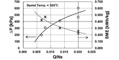
図に示す結果から、圧力損失(Δp)はQ/Nsの増加に伴い増加するのに対し、SMEはQ/Nsの増加に伴い減少することが分かった。すなわち、圧力損失とSMEは相反する傾向にあることが分かった。
実施例2~8について、圧力損失とSMEの関係を図43に示す。
図に示す結果から、圧力損失(Δp)はQ/Nsの増加に伴い増加するのに対し、SMEはQ/Nsの増加に伴い減少することが分かった。すなわち、圧力損失とSMEは相反する傾向にあることが分かった。
<粘弾性特性と表面抵抗率>
実施例2~8について、粘弾性特性と表面抵抗率の関係を図44に示す。
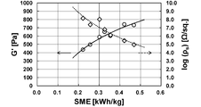
図に示す結果から、SMEの増加(Q/Nsの減少)とともにG’が増加し、表面抵抗率は低下(導電率が向上)することが分かった。すなわち、SWCNTの絡み合いはSMEに依存する。
実施例2~8について、粘弾性特性と表面抵抗率の関係を図44に示す。
図に示す結果から、SMEの増加(Q/Nsの減少)とともにG’が増加し、表面抵抗率は低下(導電率が向上)することが分かった。すなわち、SWCNTの絡み合いはSMEに依存する。
<引張特性>
実施例2~8について、引張試験の結果を図45に示す。なお、COP単独の引張強度(σγ)は61MPaであり、破断伸び(εB)は20%である。
図に示す結果から、圧力損失(Δp)の増加(Q/Nsの増加)とともに引張強度のみならず破断伸びが増加することがわかった。
実施例2~8について、引張試験の結果を図45に示す。なお、COP単独の引張強度(σγ)は61MPaであり、破断伸び(εB)は20%である。
図に示す結果から、圧力損失(Δp)の増加(Q/Nsの増加)とともに引張強度のみならず破断伸びが増加することがわかった。
<モルフォロジー観察>
実施例2~8について、モルフォロジー観察の結果を図46に示す。
図に示す結果から、以下のことが分かった。
SMEが小でΔpが大である場合、SWCNTのマクロな凝集体は微細化している。
SMEが大でΔpが小である場合、SWCNTの大きな凝集体が残存している。
実施例2~8について、モルフォロジー観察の結果を図46に示す。
図に示す結果から、以下のことが分かった。
SMEが小でΔpが大である場合、SWCNTのマクロな凝集体は微細化している。
SMEが大でΔpが小である場合、SWCNTの大きな凝集体が残存している。
<凝集面積分布の統計処理>
実施例2~8について、凝集体のサイズの分布と、20μm2以下のSWCNT凝集体が占める割合を計算し、その結果を図47,48にまとめた。
これらの図に示す結果から、Q/Nsの増加(Δpの増加)とともに分散は悪化しているが、分散のばらつきは減少していることが分かる。従って、SMEはミクロな分散を促進させ、Δpはマクロな分散を促進させると判断することができる。
実施例2~8について、凝集体のサイズの分布と、20μm2以下のSWCNT凝集体が占める割合を計算し、その結果を図47,48にまとめた。
これらの図に示す結果から、Q/Nsの増加(Δpの増加)とともに分散は悪化しているが、分散のばらつきは減少していることが分かる。従って、SMEはミクロな分散を促進させ、Δpはマクロな分散を促進させると判断することができる。
<ディスク型セグメントの収縮比の影響>
実施例2~15について、Q/Nsと圧力損失の関係を図49に示し、SMEと表面抵抗率の関係を図50に示す。
なお、図中、「XBD N30D1」が小孔の数30個のXBDを用いた実施例2~8の結果であり、「XBD N8D1」が小孔の数8個のXBDを用いた実施例9~15の結果である。
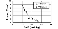
これらの図に示す結果から、収縮比を減少させる(小孔の個数を減らす)ことで、圧力損失が向上することが分かり、これにより導電性(分散)の改善も可能となることが分かった。
実施例2~15について、Q/Nsと圧力損失の関係を図49に示し、SMEと表面抵抗率の関係を図50に示す。
なお、図中、「XBD N30D1」が小孔の数30個のXBDを用いた実施例2~8の結果であり、「XBD N8D1」が小孔の数8個のXBDを用いた実施例9~15の結果である。
これらの図に示す結果から、収縮比を減少させる(小孔の個数を減らす)ことで、圧力損失が向上することが分かり、これにより導電性(分散)の改善も可能となることが分かった。
<スクリュピッチの影響>
実施例2~8及び実施例16~22について、Q/Nsと圧力損失の関係を図51に示し、SMEと表面抵抗率の関係を図52に示す。
なお、図中、「FF Pitch12」がスクリュピッチ12mmのフルフライトスクリュを用いた実施例2~8の結果であり、「FF Pitch8」がスクリュピッチ8mmのフルフライトスクリュを用いた実施例16~22の結果である。
これらの図に示す結果から、スクリュピッチの幅を減少させても、圧力損失はほぼ変化せず、導電性(分散)も殆ど改善されないことが分かった。
実施例2~8及び実施例16~22について、Q/Nsと圧力損失の関係を図51に示し、SMEと表面抵抗率の関係を図52に示す。
なお、図中、「FF Pitch12」がスクリュピッチ12mmのフルフライトスクリュを用いた実施例2~8の結果であり、「FF Pitch8」がスクリュピッチ8mmのフルフライトスクリュを用いた実施例16~22の結果である。
これらの図に示す結果から、スクリュピッチの幅を減少させても、圧力損失はほぼ変化せず、導電性(分散)も殆ど改善されないことが分かった。
<上記測定及び評価のまとめ>
本発明のディスク型セグメントで生じる圧力損失(Δp)は粘度と流量の積に比例し、Q/Nsの増加に伴い増加する。粘度と流量は混練条件を変えることで変化させることができる。
引張強度はΔpの増加に伴い大きく改善される。他方、導電性はSMEの増加に伴い改善される。この事実から、Δpが分散材のマクロな均一分散を促進させるのに対し、SMEはミクロ分散を促進させることが分かった。
SMEとΔpは相反関係にあり、これらの両立は困難であるが、小孔の数を30個から8個に減少させることで圧力損失が増加した結果から、貫通孔の透過面積を減少させることで、Δpを向上させることができることが分かった。他方、スクリュピッチを減少させることはΔpの向上にはあまり有効ではないことが分かった。
本発明のディスク型セグメントで生じる圧力損失(Δp)は粘度と流量の積に比例し、Q/Nsの増加に伴い増加する。粘度と流量は混練条件を変えることで変化させることができる。
引張強度はΔpの増加に伴い大きく改善される。他方、導電性はSMEの増加に伴い改善される。この事実から、Δpが分散材のマクロな均一分散を促進させるのに対し、SMEはミクロ分散を促進させることが分かった。
SMEとΔpは相反関係にあり、これらの両立は困難であるが、小孔の数を30個から8個に減少させることで圧力損失が増加した結果から、貫通孔の透過面積を減少させることで、Δpを向上させることができることが分かった。他方、スクリュピッチを減少させることはΔpの向上にはあまり有効ではないことが分かった。
以上のとおり、上記各実施例では、実施例1において、ポリプロピレンと多層カーボンナノチューブを用いたのと異なり、シクロオレフィンポリマーと単層ナノチューブを用いた場合でも、本発明が有効であることが明確となった。このように、本発明は、樹脂及び樹脂添加剤の種類によらず、広範に適用可能である。
特に、単層ナノチューブは、比表面積が大きいために、大きな凝集体を形成する傾向があり、分散が困難である。本発明によれば、このような混練材料であっても、良好に分散可能であり、本発明が、混練押出技術として極めて優れていることが裏付けられた。また、上記各実施例は、混練条件、XBDの形状、スクリュ構成などが分散性に与える影響を考察したものとして、本発明の意義をより明確化するものである。
特に、単層ナノチューブは、比表面積が大きいために、大きな凝集体を形成する傾向があり、分散が困難である。本発明によれば、このような混練材料であっても、良好に分散可能であり、本発明が、混練押出技術として極めて優れていることが裏付けられた。また、上記各実施例は、混練条件、XBDの形状、スクリュ構成などが分散性に与える影響を考察したものとして、本発明の意義をより明確化するものである。
〔実施例23~27〕
二軸混練押出機「ZSK18 MEGAlab」(Coperion社製。スクリュ径18mm、L/D:40)を用いて、そのバレル内に、図8に示すディスク型セグメント(XBD)を配置し、混練押出を行った。
図8に示すとおり、XBDの小孔の数は30個である。また、小孔の径は1mmであり、小孔の軸方向の幅(厚み)は3mm(他の部分も含めたディスクの軸方向の幅は7mm)である。
ポリマーブレンドのマトリックスとしてポリメタクリル酸メチル(PMMA)(三菱ケミカル(株)社製,VH001)を用いた。密度は1.19g/cm3,メルトフローレート(MFR)は2.0g/10min(230℃,3.73N)である。
また、分散相としてポリカーボネート(PC)(三菱エンジニアリングプラスチックス(株)社製,H-4000)を用いた。密度は1.20g/cm3,MFRは63g/10min(300℃,1.20kgf)である。
PCが4重量%となる割合でPMMAとPCをドライブレンドし、これをホッパーから二軸混練押出機に供給し、混練押出を行った。
二軸混練押出機におけるXBDの配置位置は図53に示すとおりとした。なお、図中の「Melting(KD)」は溶融のために用いたニーディングディスク(図10に示すもの)である。
二軸混練押出機「ZSK18 MEGAlab」(Coperion社製。スクリュ径18mm、L/D:40)を用いて、そのバレル内に、図8に示すディスク型セグメント(XBD)を配置し、混練押出を行った。
図8に示すとおり、XBDの小孔の数は30個である。また、小孔の径は1mmであり、小孔の軸方向の幅(厚み)は3mm(他の部分も含めたディスクの軸方向の幅は7mm)である。
ポリマーブレンドのマトリックスとしてポリメタクリル酸メチル(PMMA)(三菱ケミカル(株)社製,VH001)を用いた。密度は1.19g/cm3,メルトフローレート(MFR)は2.0g/10min(230℃,3.73N)である。
また、分散相としてポリカーボネート(PC)(三菱エンジニアリングプラスチックス(株)社製,H-4000)を用いた。密度は1.20g/cm3,MFRは63g/10min(300℃,1.20kgf)である。
PCが4重量%となる割合でPMMAとPCをドライブレンドし、これをホッパーから二軸混練押出機に供給し、混練押出を行った。
二軸混練押出機におけるXBDの配置位置は図53に示すとおりとした。なお、図中の「Melting(KD)」は溶融のために用いたニーディングディスク(図10に示すもの)である。
各実施例において、混練押出条件を下表のとおりとした。

〔実施例28~32〕
小孔の数が8個である図54に示すXBDを用いたこと以外は、実施例23~27と同様にして、混練押出を行った。
小孔の数が8個である図54に示すXBDを用いたこと以外は、実施例23~27と同様にして、混練押出を行った。
〔比較例3~7〕
二軸混練押出機「ZSK18 MEGAlab」(Coperion社製。スクリュ径18mm、L/D:40)を用いて、そのバレル内に、XBDではなく、図10に示すディスク型セグメント(KD)を配置し、混練押出を行った。KDの配置位置は図55のとおりとした。その他は実施例23~27と同様とした。
二軸混練押出機「ZSK18 MEGAlab」(Coperion社製。スクリュ径18mm、L/D:40)を用いて、そのバレル内に、XBDではなく、図10に示すディスク型セグメント(KD)を配置し、混練押出を行った。KDの配置位置は図55のとおりとした。その他は実施例23~27と同様とした。
〔測定及び評価〕
<粘度比>
高圧式ツインキャピラリーレオメーター(Malvern Instruments Ltd.製,Rosand RH2200)を用いて各樹脂の定常流動粘度測定を行った。熱風乾燥機にて80℃,24時間以上乾燥させた各々の樹脂を用いて、約100s-1~10000s-1のせん断速度範囲、及び240℃から280℃まで10℃刻みにて粘度計測を行い、PMMAに対するPCの粘度比を求めた。
<粘度比>
高圧式ツインキャピラリーレオメーター(Malvern Instruments Ltd.製,Rosand RH2200)を用いて各樹脂の定常流動粘度測定を行った。熱風乾燥機にて80℃,24時間以上乾燥させた各々の樹脂を用いて、約100s-1~10000s-1のせん断速度範囲、及び240℃から280℃まで10℃刻みにて粘度計測を行い、PMMAに対するPCの粘度比を求めた。
<圧力損失>
Dynisco社製圧力センサー(NP462)2対を自作した二軸押出機用バレルに取付け、XBD前後での圧力損失(ΔP)を測定した
Dynisco社製圧力センサー(NP462)2対を自作した二軸押出機用バレルに取付け、XBD前後での圧力損失(ΔP)を測定した
<分散評価>
透過電子顕微鏡(TEM)観察、ヘイズ測定、DSC測定の3点から評価した。具体的には以下のとおりである。
透過電子顕微鏡(TEM)観察、ヘイズ測定、DSC測定の3点から評価した。具体的には以下のとおりである。
(1)TEM観察
PMMA/PCポリマーブレンドの組織状態観察は、透過電子顕微鏡TEM(日本電子(株)製,JEM-2100)を用いた。二軸押出により得られたペレットをミクロトームにより厚さ約100nmの薄片に切り出し、加速電圧200kVにて観察を行った。
PMMA中のPCの平均液滴直径dPCは,画像処理システムSigmaScan Pro(Systat Software Inc.社製)を用いて、倍率40000倍にて観察したTEM像中におけるPCを約300個以上測定し、そのPCの平均粒径dPCを算出した。
PMMA/PCポリマーブレンドの組織状態観察は、透過電子顕微鏡TEM(日本電子(株)製,JEM-2100)を用いた。二軸押出により得られたペレットをミクロトームにより厚さ約100nmの薄片に切り出し、加速電圧200kVにて観察を行った。
PMMA中のPCの平均液滴直径dPCは,画像処理システムSigmaScan Pro(Systat Software Inc.社製)を用いて、倍率40000倍にて観察したTEM像中におけるPCを約300個以上測定し、そのPCの平均粒径dPCを算出した。
(2)ヘイズ測定
混練押出物を水冷により急冷し、ペレットを得た後、射出成形により板材(70mm×120mm×3.4mm)を成形し、ヘイズメーター(日本電色工業(株)社製,NDH2000)を用いて、JIS K 7136(ISO 14782)に準じヘイズ測定を行った。
混練押出物を水冷により急冷し、ペレットを得た後、射出成形により板材(70mm×120mm×3.4mm)を成形し、ヘイズメーター(日本電色工業(株)社製,NDH2000)を用いて、JIS K 7136(ISO 14782)に準じヘイズ測定を行った。
(3)DSC測定
上記(2)と同様に板材を成形した。
この板材について、示差走査熱量測定(DSC)「Q 1000」(TA Instrument社製)を用いて、下記条件で、ガラス転移温度を測定した。
・昇温10℃(K)/min 2℃~200℃範囲
・窒素雰囲気下
・測定は、一度昇温させて保持したのち、降温し、再度昇温を行ったときの昇温過程(2nd run)でのベースラインのシフトに基づいて行った。
上記(2)と同様に板材を成形した。
この板材について、示差走査熱量測定(DSC)「Q 1000」(TA Instrument社製)を用いて、下記条件で、ガラス転移温度を測定した。
・昇温10℃(K)/min 2℃~200℃範囲
・窒素雰囲気下
・測定は、一度昇温させて保持したのち、降温し、再度昇温を行ったときの昇温過程(2nd run)でのベースラインのシフトに基づいて行った。
〔結果及び考察〕
<PMMAとPCの粘度比(レオロジーデータ)>
PMMA(マトリックス)に対するPC(分散相)の粘度比(せん断速度と温度の依存性)を求めたグラフを図56に示す。
ポリマーブレンドの分散状態は粘度比に依存する。
そして、図56に示す結果から、PMMA/PCポリマーブレンドは、せん断速度(回転数が高い)が高いと粘度比が上がってしまい、分散させにくい材料であることがわかる。また、温度が低い状態でも粘度比が高くなってしまい、分散が悪くなる傾向にある材料であることが分かる。
従って、PMMA/PCポリマーブレンドは、一般に混練のハードルが高いことが分かる。
<PMMAとPCの粘度比(レオロジーデータ)>
PMMA(マトリックス)に対するPC(分散相)の粘度比(せん断速度と温度の依存性)を求めたグラフを図56に示す。
ポリマーブレンドの分散状態は粘度比に依存する。
そして、図56に示す結果から、PMMA/PCポリマーブレンドは、せん断速度(回転数が高い)が高いと粘度比が上がってしまい、分散させにくい材料であることがわかる。また、温度が低い状態でも粘度比が高くなってしまい、分散が悪くなる傾向にある材料であることが分かる。
従って、PMMA/PCポリマーブレンドは、一般に混練のハードルが高いことが分かる。
<XBDのプロセスデータ>
実施例23~32、比較例3~7における圧力損失と吐出温度データを、それぞれ図57,58に示す。
図に示す結果から、Q/Nsが大きくなるにつれて圧力損失(Δp)が上昇することが分かる。また、Q/Nsが小さいほど(SMEが高いほど)吐出温度が高く、発熱はΔpに依存しないことが分かる。すなわち、伸長流動による発熱は支配的ではない。
実施例23~32、比較例3~7における圧力損失と吐出温度データを、それぞれ図57,58に示す。
図に示す結果から、Q/Nsが大きくなるにつれて圧力損失(Δp)が上昇することが分かる。また、Q/Nsが小さいほど(SMEが高いほど)吐出温度が高く、発熱はΔpに依存しないことが分かる。すなわち、伸長流動による発熱は支配的ではない。
<PMMA中のPC分散径>
TEM観察の結果を図59に示す。液滴径dpc[nm]は、約300個の平均値である。
図に示す結果から、Q/Nsが大きくなるにつれてPCの分散径が減少する傾向にあることが分かった。
TEM観察の結果を図59に示す。液滴径dpc[nm]は、約300個の平均値である。
図に示す結果から、Q/Nsが大きくなるにつれてPCの分散径が減少する傾向にあることが分かった。
<ヘイズ値>
実施例23~32、比較例3~7について、上述のPC分散径とヘイズ値との関係を図60に示す。また、相対ヘイズ値(PMMA単独のヘイズ値に対する相対値)を図61に示す。
図に示す結果から、XBDを用いた方が、KDを用いた場合よりも、PCの液滴径が小さく、その結果、ヘイズ値も小さくなること(透明性が高いこと)が分かった。
実施例23~32、比較例3~7について、上述のPC分散径とヘイズ値との関係を図60に示す。また、相対ヘイズ値(PMMA単独のヘイズ値に対する相対値)を図61に示す。
図に示す結果から、XBDを用いた方が、KDを用いた場合よりも、PCの液滴径が小さく、その結果、ヘイズ値も小さくなること(透明性が高いこと)が分かった。
<ガラス転移温度>
実施例23~32、比較例3~7について、ガラス転移温度の測定結果を表4にまとめた。
実施例23~32、比較例3~7について、ガラス転移温度の測定結果を表4にまとめた。

上記表に示す結果から、XBDの圧力損失を向上させるにつれて、ガラス転移温度(Tg)が上昇することが分かった。
<上記測定及び評価のまとめ>
PMMA/PC系のポリマーブレンドではLCST型の相図をもつため、せん断速度の増加とそれに伴うせん断発熱は相分離を引き起こし、過剰せん断混練は適さない。
この点、本発明のディスク型セグメントは、せん断発熱を抑制しながら高い圧力損失を与えることができるため、透明性を維持しながら耐熱性を向上するプロセスを可能とする。
すなわち、本発明のディスク型セグメントは、ポリマーブレンドへの適用においても、極めて有効であることが分かった。
PMMA/PC系のポリマーブレンドではLCST型の相図をもつため、せん断速度の増加とそれに伴うせん断発熱は相分離を引き起こし、過剰せん断混練は適さない。
この点、本発明のディスク型セグメントは、せん断発熱を抑制しながら高い圧力損失を与えることができるため、透明性を維持しながら耐熱性を向上するプロセスを可能とする。
すなわち、本発明のディスク型セグメントは、ポリマーブレンドへの適用においても、極めて有効であることが分かった。
1 二軸混練押出機
11 バレル
12 ホッパー
13 サイドフィーダ
14 ベント
21 混練スクリュ
22 ディスク型セグメント
221 ディスク本体
222 軸貫通部
221a 小孔
11 バレル
12 ホッパー
13 サイドフィーダ
14 ベント
21 混練スクリュ
22 ディスク型セグメント
221 ディスク本体
222 軸貫通部
221a 小孔
Claims (8)
- バレル内に、混練材料を混練するための複数の混練スクリュと、前記混練材料の伸長流動を促進するためのディスク型セグメントを備える多軸混練機であって、
前記ディスク型セグメントは、前記混練材料の投入部より下流で前記バレル内を仕切った状態に配置されるとともに、各混練スクリュの回転軸が回転自在に貫通する複数の軸貫通部と、これらの軸貫通部の周囲に穿設され、混練材料の流路となる多数の小孔を備えていることを特徴とする多軸混練機。 - ディスク型セグメントが、小孔が穿設されたディスク本体と、このディスク本体に装着された軸貫通部となるベアリングを備えている請求項1に記載の多軸混練機。
- 小孔の混練材料流れ入口側の開口面積の総計が、バレルの内断面積の20%以下である請求項1または請求項2に記載の多軸混練機。
- 樹脂と樹脂添加剤とを含む混練材料を混練するために用いられる請求項1~請求項3のいずれかに記載の多軸混練機。
- 請求項4に記載の多軸混練機を用い、前記樹脂添加剤としてナノ粒子を投入する工程を含むことを特徴とするナノコンポジットの製造方法。
- ナノ粒子が、カーボンナノチューブ、カーボンナノファイバ、セルロースナノファイバ、グラフェン、ナノクレイ、カーボンブラックからなる群より選ばれた少なくとも1種である請求項5に記載のナノコンポジットの製造方法。
- 2種以上の異なる樹脂を含む混練材料を混練するために用いられる請求項1~請求項3のいずれかに記載の多軸混練機。
- 混練材料を混練するための複数の混練スクリュをバレル内に備える多軸混練機に用いられるディスク型セグメントであって、
前記バレル内を仕切るとともに、各混練スクリュの回転軸が回転自在に貫通する複数の軸貫通部と、これらの軸貫通部の周囲に穿設され、混練材料の流路となる多数の小孔を備えていることを特徴とするディスク型セグメント。
Priority Applications (4)
| Application Number | Priority Date | Filing Date | Title |
|---|---|---|---|
| CN201880012536.1A CN110300649B (zh) | 2017-02-22 | 2018-02-21 | 多轴混炼机和使用了该多轴混炼机的纳米复合材料的制造方法以及用于它们的盘形件 |
| EP18757298.7A EP3587060B1 (en) | 2017-02-22 | 2018-02-21 | Disk-shaped segment, and related method for producing nano-composite |
| JP2019501381A JP6532628B2 (ja) | 2017-02-22 | 2018-02-21 | 多軸混練機及びこの多軸混練機を用いたナノコンポジットの製造方法並びにこれらに用いるディスク型セグメント |
| US16/548,132 US11938657B2 (en) | 2017-02-22 | 2019-08-22 | Multi-screw kneader and method for producing nano-composite using said multi-screw kneader, and disk-shaped segment used for said kneader and said method |
Applications Claiming Priority (2)
| Application Number | Priority Date | Filing Date | Title |
|---|---|---|---|
| JP2017-030841 | 2017-02-22 | ||
| JP2017030841 | 2017-02-22 |
Related Child Applications (1)
| Application Number | Title | Priority Date | Filing Date |
|---|---|---|---|
| US16/548,132 Continuation US11938657B2 (en) | 2017-02-22 | 2019-08-22 | Multi-screw kneader and method for producing nano-composite using said multi-screw kneader, and disk-shaped segment used for said kneader and said method |
Publications (1)
| Publication Number | Publication Date |
|---|---|
| WO2018155502A1 true WO2018155502A1 (ja) | 2018-08-30 |
Family
ID=63253266
Family Applications (1)
| Application Number | Title | Priority Date | Filing Date |
|---|---|---|---|
| PCT/JP2018/006270 Ceased WO2018155502A1 (ja) | 2017-02-22 | 2018-02-21 | 多軸混練機及びこの多軸混練機を用いたナノコンポジットの製造方法並びにこれらに用いるディスク型セグメント |
Country Status (5)
| Country | Link |
|---|---|
| US (1) | US11938657B2 (ja) |
| EP (1) | EP3587060B1 (ja) |
| JP (1) | JP6532628B2 (ja) |
| CN (1) | CN110300649B (ja) |
| WO (1) | WO2018155502A1 (ja) |
Families Citing this family (1)
| Publication number | Priority date | Publication date | Assignee | Title |
|---|---|---|---|---|
| CN112388861B (zh) * | 2020-10-29 | 2022-05-17 | 无锡市瑞澳矿业科技有限公司 | 一种基于温差变换的双辊式橡胶开炼装置 |
Citations (4)
| Publication number | Priority date | Publication date | Assignee | Title |
|---|---|---|---|---|
| JPS5948136A (ja) * | 1982-09-13 | 1984-03-19 | Japan Synthetic Rubber Co Ltd | ベント押出機 |
| JPH1110709A (ja) | 1997-06-23 | 1999-01-19 | Sagara Kogyo Kk | ニーディングディスク及びニーディングディスクの製造方法 |
| WO1999061213A1 (en) * | 1998-05-25 | 1999-12-02 | Sato Iron Works Co., Ltd. | Low-friction type kneading device |
| JP2013535358A (ja) * | 2010-07-23 | 2013-09-12 | ランクセス・ドイチュランド・ゲーエムベーハー | ダイプレートが一体化された押出機およびポリマー混合物を脱気するための方法 |
Family Cites Families (7)
| Publication number | Priority date | Publication date | Assignee | Title |
|---|---|---|---|---|
| BE523318A (ja) * | 1953-07-30 | 1900-01-01 | ||
| DE1554751B1 (de) * | 1966-09-10 | 1971-01-07 | Kestermann Maschf Rolf | Schnecken-Strangpresse |
| US3447582A (en) * | 1967-08-01 | 1969-06-03 | Egan & Co Frank W | Apparatus for treating polymers and the like |
| JPH08104899A (ja) * | 1994-10-04 | 1996-04-23 | Sato Tekkosho:Kk | 多段式真空練り出し成形装置 |
| US5962036A (en) * | 1998-01-08 | 1999-10-05 | Wenger Manufacturing, Inc. | Twin screw extruder with high-speed bearing support |
| US20150275063A1 (en) * | 2012-09-19 | 2015-10-01 | Chandrashekar Raman | Thermally conductive plastic compositions, extrusion apparatus and methods for making thermally conductive plastics |
| EP2921279B1 (de) * | 2014-03-20 | 2017-02-22 | Coperion GmbH | Vorrichtung und Verfahren zur Homogenisierung von Kunststoffschmelzen |
-
2018
- 2018-02-21 CN CN201880012536.1A patent/CN110300649B/zh active Active
- 2018-02-21 EP EP18757298.7A patent/EP3587060B1/en active Active
- 2018-02-21 WO PCT/JP2018/006270 patent/WO2018155502A1/ja not_active Ceased
- 2018-02-21 JP JP2019501381A patent/JP6532628B2/ja active Active
-
2019
- 2019-08-22 US US16/548,132 patent/US11938657B2/en active Active
Patent Citations (4)
| Publication number | Priority date | Publication date | Assignee | Title |
|---|---|---|---|---|
| JPS5948136A (ja) * | 1982-09-13 | 1984-03-19 | Japan Synthetic Rubber Co Ltd | ベント押出機 |
| JPH1110709A (ja) | 1997-06-23 | 1999-01-19 | Sagara Kogyo Kk | ニーディングディスク及びニーディングディスクの製造方法 |
| WO1999061213A1 (en) * | 1998-05-25 | 1999-12-02 | Sato Iron Works Co., Ltd. | Low-friction type kneading device |
| JP2013535358A (ja) * | 2010-07-23 | 2013-09-12 | ランクセス・ドイチュランド・ゲーエムベーハー | ダイプレートが一体化された押出機およびポリマー混合物を脱気するための方法 |
Non-Patent Citations (5)
| Title |
|---|
| H.P. GRACE, CHEMICAL ENGINEERING COMMUNICATIONS, vol. 14, no. 3-6, 1982, pages 225 - 277 |
| See also references of EP3587060A4 |
| TANAKA, TATSUYA: "Changes of the mixing technology/System by a twin screw extruder and application to nano filler dispersion techniques", BANDO TECHNICAL REPORT NO. 18, vol. 2, no. 18, 3 March 2014 (2014-03-03), pages 8, XP9516319 * |
| TATSUHIRO TAKAHASHITAKESHI YASUDATAKAHIRO OOKUBOHIROSHI AWANOKOICHIRO YONETAKE: "Functionalization of carbon nanotube/polymer composite", TANSO, vol. 2006, no. 223, 2006, pages 194 - 205 |
| TATSUYA TANAKA: "Bando Technical Report", 2014, BANDO CHEMICAL INDUSTRIES, LTD., article "Nijiku Konren Oshidashiki ni yoru Konren Gijutsu/ Souchi no Hensen oyobi Nanofira Bunsan Gijutsu no Oyo (Kneading technique using twin-screw kneading extruder, transition of apparatus, and application of nano filler dispersion technology", pages: 2 - 8 |
Also Published As
| Publication number | Publication date |
|---|---|
| US20190389092A1 (en) | 2019-12-26 |
| EP3587060B1 (en) | 2022-04-06 |
| CN110300649A (zh) | 2019-10-01 |
| JPWO2018155502A1 (ja) | 2019-06-27 |
| EP3587060A1 (en) | 2020-01-01 |
| EP3587060A4 (en) | 2020-12-16 |
| JP6532628B2 (ja) | 2019-06-26 |
| CN110300649B (zh) | 2022-03-11 |
| US11938657B2 (en) | 2024-03-26 |
Similar Documents
| Publication | Publication Date | Title |
|---|---|---|
| Jimenez et al. | Electrically conductive polymer nanocomposites of polymethylmethacrylate and carbon nanofibers prepared by chaotic mixing | |
| Novais et al. | The effect of flow type and chemical functionalization on the dispersion of carbon nanofiber agglomerates in polypropylene | |
| Vatansever et al. | Development of CNC-reinforced PBAT nanocomposites with reduced percolation threshold: a comparative study on the preparation method | |
| Mishra et al. | Manipulation of thermo-mechanical, morphological and electrical properties of PP/PET polymer blend using MWCNT as nano compatibilizer: a comprehensive study of hybrid nanocomposites | |
| Lee et al. | Effect of fillers on the structure and mechanical properties of LCP/PP/SiO2 in-situ hybrid nanocomposites | |
| Sarul et al. | Effect of mixing strategy on the structure-properties of the PLA/PBAT blends incorporated with CNC | |
| WO2017169482A1 (ja) | 熱可塑性樹脂組成物及び熱可塑性樹脂組成物の製造方法 | |
| Wang et al. | Morphology evolutions and mechanical properties of in situ fibrillar polylactic acid/thermoplastic polyurethane blends fabricated by fused deposition modeling | |
| Zhang et al. | Selective localization of starch nanocrystals in the biodegradable nanocomposites probed by crystallization temperatures | |
| WO2013111862A1 (ja) | 導電性樹脂用マスターバッチの製造方法およびマスターバッチ | |
| Ab Ghani et al. | The evaluation of mechanical properties graphene nanoplatelets reinforced polylactic acid nanocomposites | |
| Wang et al. | Compatibilization of poly (lactic acid)/ethylene‐propylene‐diene rubber blends by using organic montmorillonite as a compatibilizer | |
| Doagou-Rad et al. | Influence of processing conditions on the mechanical behavior of MWCNT reinforced thermoplastic nanocomposites | |
| Kong et al. | Elongation thinning and morphology deformation of nanoparticle-filled polypropylene/polystyrene blends in elongational flow | |
| Zhan et al. | Electrical, thermal, and mechanical properties of polyarylene ether nitriles/graphite nanosheets nanocomposites prepared by masterbatch route | |
| Arigbabowo et al. | Fused filament fabrication of polyamide 6 nanographene composite for electrostatic discharge applications | |
| JP6873360B2 (ja) | 熱可塑性樹脂組成物 | |
| JP6532628B2 (ja) | 多軸混練機及びこの多軸混練機を用いたナノコンポジットの製造方法並びにこれらに用いるディスク型セグメント | |
| Fernandez et al. | The effect of nano, micro and dual scale filler reinforcement on the morphology, mechanical and barrier properties of polypropylene composites | |
| TWI721556B (zh) | 導電樹脂組合物及其製備方法 | |
| Rizvi et al. | Processing and properties of melt spun polylactide–multiwall carbon nanotube fiber composites | |
| Ding et al. | Hierarchical structure of thermotropic liquid crystalline polymer formed in blends jointly by dynamic and thermodynamic driving forces | |
| Tanoue et al. | Characterization of polypropylene/magnesium oxide/vapor-grown carbon fiber composites prepared by melt compounding | |
| Ata et al. | Effect of matrix polymer viscosity on nanofiller exfoliation during compounding | |
| Heidari Golfazani et al. | The role of nanoclay partitioning on microfibril morphology development in polypropylene/polyamide 6 nanocomposite fibers |
Legal Events
| Date | Code | Title | Description |
|---|---|---|---|
| DPE1 | Request for preliminary examination filed after expiration of 19th month from priority date (pct application filed from 20040101) | ||
| 121 | Ep: the epo has been informed by wipo that ep was designated in this application |
Ref document number: 18757298 Country of ref document: EP Kind code of ref document: A1 |
|
| ENP | Entry into the national phase |
Ref document number: 2019501381 Country of ref document: JP Kind code of ref document: A |
|
| NENP | Non-entry into the national phase |
Ref country code: DE |
|
| ENP | Entry into the national phase |
Ref document number: 2018757298 Country of ref document: EP Effective date: 20190923 |