WO2018199302A1 - ルーバー用パネルの取付構造 - Google Patents
ルーバー用パネルの取付構造 Download PDFInfo
- Publication number
- WO2018199302A1 WO2018199302A1 PCT/JP2018/017250 JP2018017250W WO2018199302A1 WO 2018199302 A1 WO2018199302 A1 WO 2018199302A1 JP 2018017250 W JP2018017250 W JP 2018017250W WO 2018199302 A1 WO2018199302 A1 WO 2018199302A1
- Authority
- WO
- WIPO (PCT)
- Prior art keywords
- pair
- spacer
- panel
- fixing plate
- mounting structure
- Prior art date
- Legal status (The legal status is an assumption and is not a legal conclusion. Google has not performed a legal analysis and makes no representation as to the accuracy of the status listed.)
- Ceased
Links
Images





Classifications
-
- E—FIXED CONSTRUCTIONS
- E04—BUILDING
- E04B—GENERAL BUILDING CONSTRUCTIONS; WALLS, e.g. PARTITIONS; ROOFS; FLOORS; CEILINGS; INSULATION OR OTHER PROTECTION OF BUILDINGS
- E04B1/00—Constructions in general; Structures which are not restricted either to walls, e.g. partitions, or floors or ceilings or roofs
- E04B1/38—Connections for building structures in general
- E04B1/388—Separate connecting elements
-
- E—FIXED CONSTRUCTIONS
- E04—BUILDING
- E04F—FINISHING WORK ON BUILDINGS, e.g. STAIRS, FLOORS
- E04F10/00—Sunshades, e.g. Florentine blinds or jalousies; Outside screens; Awnings or baldachins
- E04F10/08—Sunshades, e.g. Florentine blinds or jalousies; Outside screens; Awnings or baldachins of a plurality of similar rigid parts, e.g. slabs, lamellae
- E04F10/10—Sunshades, e.g. Florentine blinds or jalousies; Outside screens; Awnings or baldachins of a plurality of similar rigid parts, e.g. slabs, lamellae collapsible or extensible; metallic Florentine blinds; awnings with movable parts such as louvres
-
- E—FIXED CONSTRUCTIONS
- E04—BUILDING
- E04F—FINISHING WORK ON BUILDINGS, e.g. STAIRS, FLOORS
- E04F10/00—Sunshades, e.g. Florentine blinds or jalousies; Outside screens; Awnings or baldachins
- E04F10/08—Sunshades, e.g. Florentine blinds or jalousies; Outside screens; Awnings or baldachins of a plurality of similar rigid parts, e.g. slabs, lamellae
Definitions
- the present invention relates to a louver panel mounting structure.
- Patent Document 1 describes a louver having a sandwich structure in which a metal rectangular frame spacer unit is sandwiched between a pair of metal plates.
- the spacer unit includes a pair of straight tubular spacers constituting left and right frame portions and a pair of straight tubular spacers constituting upper and lower frame portions.
- This louver is installed in a standing posture between the upper and lower plates of the building.
- the louver is supported and installed by a columnar support portion and a pair of rotation restricting members installed on the lower plate.
- the louver having the sandwich structure described in Patent Document 1 may bend when it receives wind, and it is necessary to install it in a building in consideration of this point.
- An object of the present invention is to propose a louver panel mounting structure that can secure the mounting strength of a louver to a building even if it is bent by wind.
- the mounting structure of the louver panel includes a louver panel installed between an upper frame portion and a lower frame portion of a building, and an upper end portion of the louver panel attached to the upper frame portion.
- the louver panel includes a pair of plate members facing in the front-rear direction, a rectangular frame spacer positioned between the pair of plate members, and a core located in an area surrounded by the spacer between the pair of plate members. And material.
- the left and right frame portions of the spacer are constituted by a pair of right and left side spacers having a straight tube shape.
- the upper mounting structure includes an upper fixing plate that is fixed to the upper frame portion, a pair of upper mounting tools that are slidably connected to upper ends of the pair of left and right side spacers, and the pair of upper mounting members.
- the lower mounting structure includes a lower fixing plate that is fixed to the lower frame portion, a pair of lower mounting tools that are slidably connected to the lower end portions of the pair of left and right side spacers, and the pair of lower mounting members.
- Each of the fixtures has a pair of lower couplers that couple the lower fixing plate.
- Each of the pair of upper coupling tools penetrates the corresponding upper mounting tool and the upper fixing plate of the pair of upper mounting tools in the left-right direction, and the corresponding upper mounting tool is connected to the upper fixing plate. Connect to be rotatable.
- Each of the pair of lower coupling tools penetrates the corresponding lower mounting tool and the lower fixing plate of the pair of lower mounting tools in the left-right direction, and the corresponding lower mounting tool with respect to the lower fixing plate. Connect to be rotatable.
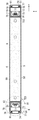
- FIG. 1 is a front view showing an essential part of a mounting structure for a louver panel according to Embodiment 1 of the present invention.
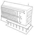
- FIG. 2 is a perspective view showing an installation example of the above-described louver panel.
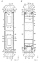
- 3A is a cross-sectional view taken along line AA in FIG. 1
- FIG. 3B is a cross-sectional view taken along line BB in FIG. 4
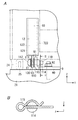
- FIG. 5A is an enlarged view of a portion D in FIG. 1, and is a view showing a louver panel, a sealing material, and a backup material by imaginary lines
- FIG. 5B is an enlarged view of an E portion in FIG. 4. 6A, FIG. 6B, and FIG.
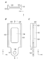
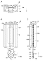
- FIG. 6C are views showing a mounting tool of the above-described louver panel mounting structure
- FIG. 6A is a plan view
- FIG. 6B is a side view
- 7A, FIG. 7B, and FIG. 7C are views showing modifications of the above-described fixture
- FIG. 7A is a plan view
- FIG. 7B is a side view
- FIG. 7C is taken along the line GG in FIG. It is sectional drawing.
- FIG. 8A is a view showing a main part of a modified example of the louver panel mounting structure
- FIG. 8B is a cross-sectional view taken along the line HH of FIG. 8A.
- FIG. 9 is a perspective view showing a modification of the above-described fixture.
- 10A, FIG. 10B, and FIG. 10C are views showing modifications of the above-described fixture, FIG. 10A is a plan view, FIG. 10B is a side view, and FIG. 10C is taken along the line II in FIG. It is sectional drawing.
- FIG. 11 is a perspective view showing a modification of the fixing plate having the same mounting structure.
- the following embodiments relate to a louver panel mounting structure, and more particularly to a sandwich louver panel mounting structure in which a rectangular frame spacer unit and a core material are sandwiched between a pair of plate members.
- FIG. 1 shows a mounting structure of a louver panel 1 (hereinafter simply referred to as “panel 1”) according to Embodiment 1 of the present invention.
- the panel 1 has a rectangular plate shape that is long in the vertical direction, and its longitudinal direction is parallel to the vertical direction between the upper frame portion 20 and the lower frame portion 21 of the building 2. Installed in a standing position.
- the thickness direction of the panel 1 (for example, the X direction in FIG. 4) is the front-rear direction, the longitudinal direction of the panel 1 is the up-down direction, and the short direction of the panel 1 is the left-right direction.
- the direction indicated by the arrow X is the front
- the direction indicated by the arrow Y is rightward
- the direction indicated by the arrow Z is upward.
- the panel 1 mounting structure (in other words, the louver panel system) includes a panel 1, an upper mounting structure 3 for mounting the upper end portion of the panel 1 to the upper frame portion 20 of the building 2, A lower mounting structure 4 for attaching the lower end portion to the lower frame portion 21 of the building 2 is provided.
- Panel 1 as shown in FIGS. 1, 3A, 3B, and 4, is provided with a pair of plate members 5 and 6 facing each other in the front-rear direction, a rectangular frame spacer 7, and a core member 8.
- the spacer 7 is located between the pair of plate members 5 and 6.
- the core member 8 is located in the entire region surrounded by the pair of plate members 5 and 6 and the spacer 7.
- the plate member 5 constituting the front surface of the panel 1 includes a rectangular plate-shaped front portion 50 positioned in front of the spacer 7 and the core member 8, a pair of side portions 51 positioned on the left and right sides of the spacer 7, and the spacer 7.
- the upper surface part 52 located and the lower surface part 53 located under the spacer 7 are included.
- the pair of side surface portions 51 protrude rearward from the left and right edges of the front surface portion 50, respectively.
- the upper surface portion 52 protrudes rearward from the upper edge of the front surface portion 50.
- the lower surface portion 53 protrudes rearward from the lower edge of the front surface portion 50.
- Each of the pair of side surface portions 51, the upper surface portion 52, and the lower surface portion 53 is substantially perpendicular to the front surface portion 50.
- the pair of side surface portions 51 are provided on the left and right edges of the front surface portion 50 in the vertical direction.
- the upper surface portion 52 is provided on the upper edge of the front surface portion 50 in the left-right direction.
- the lower surface portion 53 is provided on the lower edge of the front surface portion 50 in the left-right direction.
- the plate 6 constituting the rear surface of the panel 1 is positioned above the spacer 7, a rectangular plate-shaped rear surface portion 60 positioned behind the spacer 7 and the core material 8, side surfaces 61 positioned on the left and right of the spacer 7. It includes an upper surface portion 62 and a lower surface portion 63 located below the spacer 7.
- the pair of side surface portions 61 protrude forward from the left and right edges of the rear surface portion 60, respectively.
- the upper surface portion 62 protrudes forward from the upper edge of the rear surface portion 60.
- the lower surface portion 63 protrudes forward from the lower edge of the rear surface portion 60.
- Each of the pair of side surface portions 61, the upper surface portion 62, and the lower surface portion 63 is substantially perpendicular to the rear surface portion 60.
- the pair of side surface portions 61 are provided on the left and right edges of the rear surface portion 60 in the vertical direction.
- the upper surface portion 62 is provided on the upper edge of the rear surface portion 60 in the left-right direction.
- the lower surface portion 63 is provided on the lower edge of the rear surface portion 60 in the left-right direction.
- Each of the plate material 5 and the plate material 6 is formed by bending a metal plate.
- the metal plate include, but are not limited to, a coated steel plate, a galvanized steel plate, a Galvalume steel plate (registered trademark), an SGL (registered trademark) steel plate, a stainless steel plate, an aluminum steel plate, and a titanium plate.
- the thickness of the metal plate is, for example, 0.35 mm to 1.2 mm.
- the spacer 7 includes a pair of right and left side spacers 70 that form the left and right frame portions of the spacer 7, a straight tubular upper spacer 71 that forms the upper frame portion of the spacer 7, and a lower frame portion of the spacer 7.
- a straight tubular lower spacer 72 is included.
- the vertical length of the pair of left and right side spacers 70 is the same.
- the left and right lengths of the upper spacer 71 and the lower spacer 72 are the same.
- the longitudinal lengths (vertical lengths) of the pair of left and right side spacers 70 are longer than the longitudinal lengths (left and right lengths) of the upper spacer 71 and the lower spacer 72.
- the pair of left and right side spacers 70, the upper spacer 71, and the lower spacer 72 have the same length (that is, thickness) in the front-rear direction.
- each of the pair of left and right side spacers 70 includes a spacer main body 73 having a rectangular frame shape in a cross section and a decorative cover 74 positioned outside the spacer main body 73 in the left-right direction.
- the decorative cover 74 is positioned to the right of the spacer body 73
- the decorative cover 74 is positioned to the left of the spacer body 73.
- Each of the pair of left and right side spacers 70 is an aluminum extrusion molded product in which a spacer main body 73 and a decorative cover 74 are integrally provided.
- Each of the pair of left and right side spacers 70 has a constant cross-sectional shape in the vertical direction.
- the right side spacer 70 and the left side spacer 70 are symmetrical to each other.
- the left side spacer 70 will be described.
- the decorative cover 74 includes a pair of projecting piece portions 740 projecting leftward from the front and rear portions of the left frame portion of the spacer body 73, and a pair of projecting piece portions 740.
- a rectangular plate-like cover main body 741 integrated with the respective front end portions (left end portions) is provided.
- the length of the cover main body 741 in the front-rear direction is substantially the same as the length of the spacer main body 73 in the front-rear direction.
- the cover main body 741 is positioned with a gap between it and the spacer main body 73.
- a concave portion 742 is formed in the center portion in the front-rear direction of the surface (that is, the right surface) of the cover main body 741 on the spacer main body 73 side.
- a region surrounded by the cover main body 741, the pair of projecting piece portions 740, and the spacer main body 73 has a rectangular cross section and is separated from the inner region of the spacer main body 73.
- the side spacer 70 includes a receiving piece 75 extending forward from the central portion in the left-right direction of the front projecting piece 740 and a receiving piece extending forward from the center in the left-right direction of the rear projecting piece 740. 75.
- An insertion hole 76 into which a fixing tool such as a screw can be inserted and fixed is formed between the front receiving piece 75 and the spacer body 73.
- an insertion hole 76 into which a fixing tool such as a screw can be inserted and fixed is formed between the rear receiving piece 75 and the spacer body 73.
- the side spacer 70 is formed between the front receiving piece 75 and the cover main body 741, and is formed between the front groove portion 77 opened to the front side, the rear receiving piece 75 and the cover main body 741, and opened to the rear side.
- the rear groove portion 78 is further provided.
- the panel 1 further includes a cover material 79 attached to the upper and lower ends of each of the pair of side spacers 70.
- the panel 1 includes four cover members 79.
- the four cover members 79 have the same dimensions and shapes.
- Each cover material 79 includes an inner cover part 790 having the same front and rear width as the spacer body 73 and an outer cover part 791 having the same front and rear width as the distance between the pair of projecting piece parts 740.
- the inner cover portion 790 of each cover member 79 covers from the pair of receiving pieces 75 to the central portion in the left-right direction of the spacer body 73.
- the outer cover 791 covers from the pair of receiving pieces 75 to the cover main body 741.
- Each cover material 79 is attached to the upper end and the lower end of each of the pair of side spacers 70 by a fixture such as a screw driven into the front and rear insertion holes 76.
- the upper spacer 71 has the same structure as the lower spacer 72 rotated 180 degrees on the vertical plane.
- the lower spacer 72 will be described in detail.
- the lower spacer 72 has a recess 720 that is recessed so as to open downward on its lower surface.
- the recess 720 is provided on the lower surface of the lower spacer 72 in the longitudinal direction (left-right direction).
- the lower spacer 72 has a constant cross-sectional shape along the longitudinal direction.
- the lower spacer 72 is an extruded product made of aluminum.
- the recess 720 is located at the center in the front-rear direction on the lower surface of the lower spacer 72.
- the lower spacer 72 has a pair of flat portions 721 located on the lower surface of the lower spacer 72 before and after the recess 720.
- the lower surface portion 53 of the plate material 5 is disposed so as to cover the front flat portion 721
- the lower surface portion 63 of the plate material 6 is disposed so as to cover the rear flat portion 721.
- the recess 720 is not covered by either the lower surface portion 53 or the lower surface portion 63.
- the lower spacer 72 further has insertion holes 722 respectively provided inside the corner portion formed by the recess 720 and the front flat portion 721 and inside the corner portion formed by the recess 720 and the rear flat portion 721.
- Each insertion hole 722 can be inserted and fixed by a fixing tool such as a screw.
- the panel 1 further includes a closing plate 723 attached to the left and right end faces of the lower spacer 72, respectively.
- Each closing plate 723 is attached to the lower spacer 72 by a fixing tool such as a screw inserted and fixed in each insertion hole 722.
- Each closing plate 723 is positioned between the lower spacer 72 and the left and right side spacers 70.
- Each closing plate 723 is a substantially U-shaped plate material opened downward. Each closing plate 723 is attached to the lower spacer 72 so as to close the entire remaining portion of the lower half of the opening on either the left or right end surface of the lower spacer 72 except the recess 720.
- Each closing plate 723 is a plate body covered with an elastic member such as an aluminum plate material or butyl tape, for example. Each closing plate 723 is attached so as to be located slightly above the lower surface (flat portion 721) of the lower spacer 72. A sealing material 724 is filled below each closing plate 723.
- the upper spacer 71 has a recess 710, a pair of front and rear flat portions 711, and a pair of front and rear insertion holes 712 corresponding to the recess 720 of the lower spacer 72, a pair of front and rear flat portions 721, and a pair of front and rear insertion holes 722.
- the upper surface portion 52 of the plate material 5 is disposed so as to cover the front flat portion 711, and the upper surface portion 62 of the plate material 6 is disposed so as to cover the rear flat portion 711.
- the recess 710 is not covered by either the lower surface portion 53 or the lower surface portion 63.
- the panel 1 further includes closing plates 713 attached to the left and right end surfaces of the upper spacer 71, respectively.
- Each closing plate 713 is attached to the upper spacer 71 by a fixing tool such as a screw inserted and fixed in each insertion hole 712.
- Each closing plate 713 is positioned between the upper spacer 71 and the left and right side spacers 70.
- Each closing plate 713 is the same as each closing plate 723.
- Each closing plate 723 is attached so as to be located slightly below the upper surface (flat portion 711) of the upper spacer 71.
- a sealing material 714 is filled above each closing plate 713.
- the upper spacer 71 is disposed so as to be interposed between the upper ends of the pair of side spacers 70.
- the lower spacer 72 is disposed so as to be interposed between the lower ends of the pair of side spacers 70.
- the core material 8 is composed of a plurality of block bodies arranged in the left-right direction so that the overall shape forms one plate.
- Each of the plurality of block bodies is formed by solidifying a fibrous inorganic material such as rock wool or glass wool with a binder or the like.
- the core material 8 is disposed on the entire region surrounded by the spacer 7.
- the core material 8 may be a resin foam material (urethane foam, phenol foam, styrene foam, etc.) filled in the entire region surrounded by the spacer 7.
- the spacer 7 and the core material 8 are bonded and fixed to the entire front surface portion 50 of the plate material 5 and the entire rear surface portion 60 of the plate material 6.
- the left and right side surfaces 51 of the plate material 5 are accommodated in the front groove portions 77 of the pair of side spacers 70, respectively, and the left and right side surface portions 61 of the plate material 6 are accommodated in the rear groove portions 78 of the pair of side spacers 70, respectively. .
- the upper surface portion 52 of the plate material 5 covers the front half of the upper surface of the cover material 79 attached to the upper ends of the pair of side spacers 70 and the upper surface of the flat portion 711 on the front side of the upper spacer 71.
- the lower surface portion 53 of the plate material 5 covers the front half of the lower surface of the cover material 79 attached to the respective lower ends of the pair of side spacers 70 and the lower surface of the flat portion 721 on the front side of the lower spacer 72.
- the upper surface portion 62 of the plate member 6 covers the rear half of the upper surface of the cover material 79 attached to the upper ends of the pair of side spacers 70 and the upper surface of the flat portion 711 on the rear side of the upper spacer 71.
- the lower surface portion 63 of the plate material 6 covers the rear half of the lower surface of the cover material 79 attached to the lower ends of the pair of side spacers 70 and the lower surface of the flat portion 721 on the rear side of the lower spacer 72.
- the lower mounting structure 4 includes a lower fixing plate 9 that is fixed to the lower frame portion 21 and a pair of lower portions that are slidably connected to the lower ends of the pair of left and right side spacers 70.
- the fixture 10 and the pair of lower fixtures 10 are connected to the lower fixing plate 9.
- Each of the pair of lower couplers 11 penetrates the corresponding lower fixture 10 and the lower fixing plate 9 out of the pair of lower fixtures 10 in the left-right direction, and connects the corresponding lower fixture 10 to the lower fixing plate 9. And are configured to be rotatably connected.
- the lower fixing plate 9 has a rectangular plate-like main body 90 and a lower protrusion 91 extending upward from the left and right ends of the main body 90.
- the length of the main body 90 in the left-right direction is substantially the same as the length of the lower spacer 72 in the left-right direction.
- the main body 90 is fixed to the lower frame portion 21 by a fixture 92 such as an anchor bolt.
- the lower protruding portion 91 extends upward from the center portion in the front-rear direction among the left and right ends of the main body portion 90, and has a shorter length in the front-rear direction than the main body portion 90.
- the length of the lower protrusion 91 in the front-rear direction is smaller than the distance between the lower surface portion 53 and the lower surface portion 63.
- the lower protruding portion 91 is configured by one rectangular plate piece.
- the lower fixing plate 9 is formed by bending a steel plate.
- Each of the left and right pair of lower protrusions 91 has a through-hole 910 penetrating in the left-right direction.
- the pair of lower fixtures 10 have the same shape and dimensions. Below, the lower fixture 10 located in the left side among a pair of lower fixtures 10 is demonstrated first.
- the lower fixture 10 includes a lower fitting portion 12 that is fitted into the lower end portion of the left side spacer 70, and a lower connecting piece 13 that extends downward from the lower fitting portion 12. .
- the lower connecting piece 13 has a smaller front-rear width than the lower fitting portion 12.
- the lower fitting portion 12 includes a main body portion 120 that is H-shaped in plan view and a pair of front and rear elastic members 121 that are attached to the outer surface of the main body portion 120.
- the main body 120 includes a pair of front and rear rectangular plate-shaped flange portions 122, a center portion in the left-right direction of the front flange portion 122, and left and right sides of the rear flange portion 122.
- a rectangular plate-like web portion 123 positioned between the central portions in the direction.
- the web portion 123 has a rectangular hole 124 penetrating in the left-right direction.
- the hole 124 is located in a central portion of the web portion 123 in the vertical direction and the front-rear direction.
- the front surface and the left and right side surfaces of the front flange portion 122 are covered with the front elastic member 121 in the vertical direction.
- the rear surface and the left and right side surfaces of the rear flange portion 122 are covered with the rear elastic member 121 in the vertical direction.
- the lower connecting piece 13 extends downward from the center portion in the front-rear direction of the lower surface of the web portion 123 of the lower fitting portion 12.
- the lower connecting piece 13 has a flat plate shape.
- the length (namely, thickness) of the lower connecting piece 13 in the left-right direction is the same as the length (namely, thickness) of the web portion 123 in the left-right direction.
- the upper part of the lower connecting piece 13 has a constant front-rear width in the vertical direction, and the lower part of the lower connecting piece 13 is provided so that the front-rear width becomes smaller toward the lower side.
- the lower surface of the lower connecting piece 13 has a downwardly convex arc shape.
- the shape of the lower surface of the lower connection piece 13 should just have a small front-back width, and may be shapes other than circular arc shape.
- the lower connecting piece 13 has a through hole 130 penetrating in the left-right direction. The through hole 130 is located at a lower portion of the lower connecting piece 13.
- the main body 120 of the lower fitting portion 12 is a casting made of a metal such as iron, for example.
- the main-body part 120 may be manufactured not only by casting but by other methods, such as welding and a press.
- Each of the front and rear elastic members 121 is made of, for example, ethylene / propylene / diene rubber.
- Each of the front and rear elastic members 121 is not limited to rubber, and may be formed of other elastic materials.
- the front and rear elastic members 121 are elastically pressed against the inner peripheral surface of the spacer body 73 of the side spacer 70, so that the lower fixture 10 moves up and down with respect to the side spacer 70. It is slidably connected.
- the lower surface portion 53 that closes the front side of the opening at the lower end of the side spacer 70 and the lower surface portion 63 that closes the rear side of the opening the lower fitting portion 12 is prevented from coming out from the side spacer 70.
- the pair of lower couplers 11 have the same shape and dimensions in this embodiment.
- Each of the pair of lower connectors 11 includes a screw 110 and a pair of washers 111.
- the screw 110 includes a head portion 112 provided with a hole or a groove for turning with a tool, and a shaft portion 113 extended from the head portion 112.
- the outer dimension (outer diameter) of the head part 112 is larger than the outer diameter of the shaft part 113.
- the screw 110 is a screw having a detent function, and is, for example, Nojirok (registered trademark).
- Each of the pair of lower couplers 11 includes the shaft portion 113 of the screw 110 penetrating the washer 111, the lower connector piece 13, the washer 111, and the lower projecting portion 91 in this order. 91 is rotatably connected.
- the state where the lower connecting piece 13 and the lower protruding portion 91 are connected is maintained by the detent function of the screw 110.
- the screw 110 itself may not have a detent function, a nut may be fixed to the shaft portion 113 of the screw 110, or the through hole 910 of the lower protrusion 91 may be a screw hole.
- a nut may be fixed to the inner surface in the left-right direction of the lower protrusion 91 by welding or the like.
- the upper mounting structure 3 includes a pair of upper fixing plates 14 that are slidably connected to the upper fixing plate 14 fixed to the upper frame portion 20 and upper ends of a pair of left and right side spacers 70.
- the fixture 15 and the pair of upper fixtures 15 are connected to the upper fixing plate 14.
- Each of the pair of upper coupling tools 16 penetrates the corresponding upper mounting tool 15 and the upper fixing plate 14 in the left-right direction among the pair of upper mounting tools 15, and the corresponding upper mounting tool 15 is connected to the upper fixing plate 14. And are configured to be rotatably connected.
- the upper mounting structure 3 is the same structure as the lower mounting structure 4 rotated 180 degrees on the vertical plane. That is, the upper fixing plate 14 has the same structure as that of the lower fixing plate 9 and includes a main body portion 140 and a pair of left and right upper protruding portions 141. Each of the pair of left and right upper protrusions 141 has a through hole.
- the main body 140 is fixed to the upper frame 20 by a fixing tool 142 such as an anchor bolt.
- the pair of upper fixtures 15 have the same structure as the pair of lower fixtures 10, and an upper fitting portion 17 fitted into the upper end portion of the side spacer 70 and an upper connecting piece extended upward from the upper fitting portion 17. 18 is included.
- the upper connecting piece 18 has a smaller front-rear width than the upper fitting portion 17. The upper part of the upper connecting piece 18 is provided so that the front-rear width becomes smaller toward the upper side.
- the upper fixture 15 By elastically pressing the elastic members before and after the upper fitting portion 17 against the inner peripheral surface of the spacer main body 73 of the side spacer 70, the upper fixture 15 can slide up and down with respect to the side spacer 70. Connected. The upper fitting portion 17 is prevented from coming out of the side spacer 70 by the upper surface portion 52 that blocks the front side of the opening at the upper end of the side spacer 70 and the upper surface portion 62 that blocks the rear side of the opening.
- the pair of upper couplers 16 have the same structure as the pair of lower couplers 11, and include screws and a pair of washers.
- the screw has, for example, a detent function.
- Each of the pair of upper couplers 16 has a screw shaft that passes through the washer, the upper coupling piece 18, the washer, and the upper projecting portion 141 in this order, so that the upper coupling piece 18 is connected to the upper projecting portion 141 in this order.
- Connect to be rotatable the state where the upper connecting piece 18 and the upper projecting portion 141 are connected is maintained by the detent function of the screw.
- the screw itself may not have a detent function, a nut may be fastened to the shaft portion of the screw, and the through hole of the upper protruding portion 141 may be a screw hole.
- the mounting structure of the panel 1 further includes a support member 19 that is disposed between the panel 1 and the lower fixing plate 9 and supports the panel 1 so as to be swingable.
- the panel 1 supported by the support member 19 can swing so that the lower surface of the panel 1 is tilted to the lower right or the lower surface of the panel 1 is tilted to the lower left with the supported portion as the center.
- the support member 19 is, for example, a rubber cuboid block or an aluminum square pipe.
- the support member 19 supports the panel 1 at a position away from the lower fixing plate 9 in a state where the upper portion of the support member 19 is accommodated in the concave portion 720 in the central portion of the lower spacer 72 in the left-right direction.
- the support member 19 is disposed at a position overlapping the center of gravity of the panel 1 in the vertical direction.
- a spacer 7 and a core material 8 are fixed between the plate material 5 and the plate material 6, and a pair of lower fixtures 10, a pair of upper fixtures 15, and four covers are attached to the left and right side spacers 70.
- a panel to which a material 79 is attached is used.
- Each of the pair of lower fixtures 10 and each of the pair of upper fixtures 15 is inserted into the inside (that is, the back side) in the longitudinal direction of the side spacer 70.
- the lower fixing plate 9 is fixed to the lower frame portion 21 with a plurality of fixing tools 92
- the upper fixing plate 14 is fixed to the upper frame portion 20 with a plurality of fixing tools 142.
- the lower fixing plate 9 and the upper fixing plate 14 are fixed so as to face each other in the vertical direction.
- the panel 1 is disposed between the lower fixing plate 9 and the upper fixing plate 14, and the upper connecting pieces 18 of the pair of upper mounting tools 15 are drawn upward from the pair of left and right side spacers 70 of the panel 1.
- the upper connecting pieces 18 are connected to the left and right upper projecting portions 141 of the upper fixing plate 14 on a one-to-one basis using a pair of upper connecting tools 16.
- the panel 1 is lifted upward, and the lower connecting pieces 13 of the pair of lower fixtures 10 are pulled out downward from the side spacers 70 of the panel 1, and the lower connecting pieces 13 are placed under the left and right sides of the lower fixing plate 9.
- the protrusions 91 are connected one-on-one with the pair of lower connectors 11.
- the support member 19 is disposed on the center portion in the left-right direction of the lower fixing plate 9, the panel 1 is lowered and placed on the support member 19, and the left-right direction of the recess 720 of the lower spacer 72 of the panel 1 is placed.
- the upper part of the support member 19 is housed in the center.
- the gap between the lower frame portion 21 and the panel 1 is filled with an elastically deformable sealing material 24 in a rectangular frame shape in plan view, and the gap is filled with the sealing material 24.
- the sealing material 24 is filled in a rectangular frame shape in plan view with one backup material 25 arranged between the lower left and right cover members 79 and the lower frame portion 21.
- the support member 19 and the lower mounting structure 4 are covered with the sealing material 24.
- the gap between the upper frame portion 20 and the panel 1 is filled with an elastically deformable sealing material 24 in a rectangular frame shape in plan view, and the gap is filled with the sealing material 24.
- the sealing material 24 is filled in a rectangular frame shape in plan view with one backup material 25 arranged between the upper left and right cover members 79 and the upper frame portion 20.
- the upper mounting structure 3 is covered with the sealing material 24.
- the pair of left and right upper mounting tools 15 connected to the upper end of the panel 1 are axially oriented with respect to the upper fixing plate 14 in the left-right direction. It is connected so that it can rotate around the shaft portion of the upper connector 16.
- the pair of left and right lower mounting tools 10 connected to the lower end of the panel 1 is connected to the lower fixing plate 9 with the lower connecting tool 11 having the horizontal direction as the axial direction.
- the shaft portion 113 is connected to be rotatable.
- each of the pair of upper mounting tools 15 and the pair of lower mounting tools 10 corresponds to the degree of bending of the panel 1. Can rotate and tilt.
- each of the pair of upper fixtures 15 and the pair of lower fixtures 10 elastically presses against the inner peripheral surface of the side spacer 70 when rotating and tilting corresponding to the degree of bending of the panel 1. However, it can slide in the length direction in the side spacer 70. Therefore, each of the pair of upper fixtures 15 and the pair of lower fixtures 10 can also be prevented from being deformed by receiving an excessive load from the side spacer 70 when rotating and tilting.
- the pair of upper mounting members 15 and the pair of upper projecting portions 141 of the upper fixing plate 14 are connected, and the upper connecting member 16 is inserted from the side of the panel 1. Easy to install. Moreover, the connection by a pair of lower connector 11 is also the same.
- each of the pair of upper mounting tools 15 has a smaller front-rear width of the upper connecting piece 18, and furthermore, an upper front-rear width of the upper connecting piece 18 is smaller toward the upper side.
- the pair of upper fixtures 15 rotate, the upper connecting piece 18 can be prevented from coming into contact with the upper frame portion 20 and preventing the rotation. The same applies to the pair of lower fixtures 10.
- the lower ends of the pair of left and right upper protrusions 141 of the upper fixing plate 14 can be accommodated in the upper ends of the pair of left and right side spacers 70.
- the upper ends of the left and right pair of lower protrusions 91 can be accommodated in the lower ends of the pair of left and right side spacers 70. Therefore, in the panel 1 mounting structure of the present embodiment, the pair of left and right upper protrusions 141 of the upper fixing plate 14 and the pair of left and right lower protrusions 91 of the lower fixing plate 9 come into contact with the panel 1 and are deformed or damaged. Can be prevented.
- the panel 1 is swingably attached to the lower frame portion 21 and the upper frame portion 20. Therefore, in the panel 1 mounting structure of the present embodiment, when an earthquake occurs, the panel 1 can swing following the interlayer displacement, and the panel 1 can be prevented from dropping or breaking.
- Each of the pair of lower fixtures 10 is not limited to the above-described H-shape in plan view, and may have other shapes.
- Each of the pair of lower fixtures 10 includes, for example, a main body 120 having a rectangular plate shape (rectangular shape in a plan view), and a main body 120 as shown in FIGS. 7A, 7B, and 7C. It may be configured by a pair of front and rear elastic members 121 attached to the portion 120.
- the main body 120 is made of a metal such as iron or stainless steel, for example. A similar modification can be adopted for the pair of upper fixtures 15.
- the length in the front-rear direction of the lower connecting piece 13 may be the same as the length in the front-rear direction of the main body 120 of the lower fitting portion 12. Further, in each of the pair of upper fixtures 15, the length in the front-rear direction of the upper connecting piece 18 may be the same as the length in the front-rear direction of the main body portion of the upper fitting portion 17.
- Each of the pair of lower fixtures 10 may not be formed such that the lower part of the lower connecting piece 13 has a lower front-rear width toward the lower side, and the lower connecting piece 13 has a constant front-rear width in the vertical direction. There may be.
- each of the pair of upper fixtures 15 may not be formed such that the upper and lower widths of the upper connecting piece 18 become smaller toward the upper side, and the upper connecting piece 18 has a constant front and rear width in the vertical direction. It may be.
- the lower end portion of the upper protruding portion 141 of the upper fixing plate 14 may not be within the upper end portion of the side spacer 70 and may be positioned above the side spacer 70. Further, the upper end portion of the lower protruding portion 91 of the lower fixing plate 9 may not be within the lower end portion of the side spacer 70 and may be positioned below the side spacer 70.
- One of the pair of lower couplers 11 is replaced with a pin 114 that does not have a thread groove and a detachable attachment to the tip of the pin 114, as shown in FIGS. 8A and 8B, instead of the screw 110.
- a snap pin 115 for stopping may be provided. The same applies to the pair of upper couplers 16.
- the cover main body 741 of the decorative cover 74 is not limited to a rectangular plate shape, and for example, the outer surface in the left-right direction (on the side opposite to the spacer main body 73) is a rounded surface that is a convex curved surface with a circular cross section. It may be molded. In this case, when the panel 1 is used as an exterior louver, it is possible to suppress the generation of wind noise from the cover body 741. Further, the cover main body 741 can be selected as appropriate other than a rectangular plate shape or a shape having a rounded surface.
- the lower spacer 72 and the side spacer 70 may be arranged in direct contact with each other without using the closing plate 723 and the sealing material 724.
- the upper spacer 71 and the side spacer 70 may be arranged in direct contact with each other without using the closing plate 713 and the sealing material 714.
- the upper spacer 71 may be a straight pipe having a rectangular frame shape with no recess 710.
- Each of the pair of lower fixtures 10 includes a main body portion 120 in which the lower fitting portion 12 further includes a pair of support portions 125, as in the modifications shown in FIGS. 9, 10A, 10B, and 10C. You may be comprised with the cylindrical elastic member 126 attached to the main-body part 120.
- the lower connecting piece 13 includes a recess 132 positioned around each through-hole 130 on each of the left and right surfaces, a washer 131 disposed in each recess 132, and a hole 133 positioned above the through-hole 130. Furthermore, you may have.
- the pair of support portions 125 protrudes to the left from the upper end portion and the lower end portion of the web portion 123.
- Each of the pair of support portions 125 has a rectangular plate shape.
- the web portion 123 further has a circular hole 127 penetrating in the left-right direction.
- One hole 127 is provided in each portion of the web portion 123 between the upper support portion 125 and the hole 124, and a portion between the hole 124 and the lower support portion 125.
- the elastic member 126 has a rectangular tube shape, and has a mounting portion 1260 that is recessed inward in a part of the circumferential direction. In the present embodiment, the elastic member 126 has a pair of left and right attachment portions 1260.
- a part of the elastic member 126 is in contact with the front surface and the left and right side surfaces of the front flange portion 122, and another part is in contact with the rear surface and the left and right side surfaces of the rear flange portion 122, and a pair of left and right mounting portions 1260 is provided. Is mounted on the main body 120 so that one of the two is positioned between the upper and lower support portions 125. The upper and lower support portions 125 prevent the elastic member 126 from coming off the main body portion 120.
- the elastic member 126 and the washer 131 are made of, for example, ethylene / propylene / diene rubber or chloroprene rubber.
- the elastic member 126 and the washer 131 are not limited to rubber, and may be formed of other elastic materials. By providing the washer 131 having elasticity around the through-hole 130, it is possible to prevent the inserted pin 114 from rattling. A similar modification can be adopted for each of the pair of upper fixtures 15.
- the lower fixing plate 9 may not be composed of one member but may be composed of two members arranged side by side.
- FIG. 11 shows one of the two members constituting the lower fixing plate 9. The two members have the same structure.
- the fixed plate 93 shown in FIG. 11 has a rectangular plate-shaped main body portion 94 and a protruding portion 95 extending upward from one end portion of the main body portion 94 in the left-right direction.
- the main body portion 94 is provided with an insertion hole 940 through which a fixture 92 such as an anchor bolt is inserted.
- the main body portion 94 is fixed to the lower frame portion 21 by a fixing tool 92.
- the protruding portion 95 is composed of a pair of protruding pieces 950.
- the pair of projecting pieces 950 are positioned in parallel with an interval in the left-right direction.
- Each of the pair of protruding pieces 950 is a plate having a semi-elliptical shape in a side view.
- Each of the pair of projecting pieces 950 has a through hole 951 penetrating in the left-right direction.
- the pair of left and right lower protrusions 91 provided in the lower fixing plate 9 is configured by two protrusions 95 (four protrusions 950) of two fixing plates 93 arranged side by side.
- the fixed plate 93 is a casting made of a metal such as iron.
- the lower connecting piece 13 of the lower fixture 10 is disposed between the pair of projecting pieces 950.
- the lower connector 11 connects the pair of protruding pieces 950 and the lower connecting piece 13.
- the gap between the pair of protruding pieces 950 and the lower connecting piece 13 is filled with an elastic washer 131. be able to.
- a similar modification can be adopted for the upper fixing plate 14, and the upper fixing plate 14 may be composed of two fixing plates 93.
- the fixed plates 9 and 14 may be constituted by four fixed plates 93.
- the mounting structure of the panel (1) according to the first aspect of the present invention has the following first feature.
- the mounting structure of the panel (1) includes the panel (1) and the panel (1) installed between the upper frame part (20) and the lower frame part (21) of the building (2).
- the panel (1) includes a pair of plate members (5, 6) facing in the front-rear direction, a rectangular frame spacer (7) positioned between the pair of plate members (5, 6), and a pair of plate members (5, 5). It has the core material (8) located in the area
- the left and right frame portions of the spacer (7) are constituted by a pair of right and left side spacers (70) having a straight tubular shape.
- the upper mounting structure (3) includes a pair of upper fixing plates (14) that are fixed to the upper frame portion (20) and a pair of left and right side spacers (70) that are slidably connected in the upper and lower directions.
- the upper fixture (15) has a pair of upper couplers (16) for coupling the upper fixture (15) to the upper fixing plate (14).
- the lower mounting structure (4) includes a pair of a lower fixing plate (9) fixed to the lower frame portion (21) and a pair of left and right side spacers (70) slidably connected to the lower ends thereof.
- the lower fixture (10) has a pair of lower couplers (11) for coupling the lower fixture (10) and the lower fixing plate (9).
- Each of the pair of upper coupling tools (16) passes through the corresponding upper mounting tool (15) and the upper fixing plate (14) in the left-right direction among the pair of upper mounting tools (15), and corresponds to the corresponding upper mounting tool. (15) is rotatably connected to the upper fixing plate (14).
- Each of the pair of lower couplers (11) passes through the corresponding lower fixture (10) and the lower fixing plate (9) in the left-right direction of the pair of lower fixtures (10), and corresponds to the lower fixture. (10) is rotatably connected to the lower fixing plate (9).
- each of the pair of upper fixtures (15) Corresponding to the degree of bending of the panel (1), it can rotate and tilt around the upper connector (16).
- each of a pair of lower attachment tools (10) can rotate and incline around the lower connection tool (11) corresponding to the bending state of the panel (1).
- each of the pair of upper mounting tools (15) and the pair of lower mounting tools (10) is provided. It is possible to suppress deformation due to an excessive load. Therefore, in the mounting structure of the panel (1) of the first aspect, even if the panel (1) may be bent by the wind, the building by the pair of upper mounting tools (15) and the pair of lower mounting tools (10). The mounting strength of the panel (1) with respect to (2) can be ensured.
- the mounting structure of the panel (1) of the second aspect according to the present invention has the following second characteristic in addition to the above first characteristic. Prepare.
- each of the pair of upper mounting tools (15) is located in the upper end portion of the corresponding side spacer (70) among the pair of left and right side spacers (70).
- Each of the pair of lower fittings (10) includes a lower fitting part (12) fitted into a lower end part of a corresponding side spacer (70) of a pair of left and right side spacers (70), and a lower fitting part (12 ), And a lower connecting piece (13) through which the corresponding lower connecting tool (11) of the pair of lower connecting tools (11) passes.
- the upper connecting piece (18) has a smaller front-rear width than the upper fitting part (17), and the lower connecting piece (13) has a smaller front-rear width than the lower fitting part (12).
- each of the pair of upper mounting tools (15) corresponds to the degree of bending of the panel (1)
- the upper connecting piece (18) can be prevented from coming into contact with the upper frame portion (20) and hindering rotation.
- the lower connection piece (13) is lowered to the lower frame. It can suppress that it contacts a part (21) and becomes obstructive of rotation.
- the panel (1) mounting structure according to the third aspect of the present invention has the following third and second features in addition to the first and second features described above.
- the panel (1) mounting structure of the third mode is such that the upper part of the upper connecting piece (18) is formed such that the front and rear width becomes smaller toward the upper side, and the lower part of the lower connecting piece (13) is provided on the lower side. It is formed so that the front-rear width becomes smaller.
- each of the pair of upper mounting tools (15) corresponds to the degree of bending of the panel (1), It is possible to further suppress the upper surface of the upper connecting piece (18) from coming into contact with the upper frame portion (20) when it rotates and tilts around the connecting tool (16). Moreover, when each of a pair of lower attachment tools (10) rotates and inclines around the lower connection tool (11) corresponding to the bending state of the panel (1), the lower surface of the lower connection piece (13) is Contact with the lower frame portion (21) can be further suppressed.
- the attachment structure of the panel (1) of the fourth aspect according to the present invention is the attachment of the panel (1) of any of the first to fourth aspects.
- the structure has the following fourth feature.
- the upper fixing plate (14) protrudes downward, and the corresponding upper connector (16) of the pair of upper connectors (16) penetrates.
- the lower fixing plate (9) has a pair of left and right lower protrusions (91) that protrude upward and through which the corresponding lower connector (11) of the pair of lower connectors (11) passes.
- the lower ends of the left and right pair of upper protrusions (141) are accommodated within the upper ends of the pair of left and right side spacers (70), and the upper ends of the left and right pair of lower protrusions (91) are aligned with the pair of left and right side spacers ( 70).
- the upper projecting portion (141) and the lower projecting portion (91) hit the panel (1) and are deformed or damaged. Can be prevented.
Landscapes
- Engineering & Computer Science (AREA)
- Architecture (AREA)
- Civil Engineering (AREA)
- Structural Engineering (AREA)
- Physics & Mathematics (AREA)
- Electromagnetism (AREA)
- Specific Sealing Or Ventilating Devices For Doors And Windows (AREA)
- Fencing (AREA)
- Building Awnings And Sunshades (AREA)
- Blinds (AREA)
- Building Environments (AREA)
Abstract
Description
図1には、本発明に係る実施形態1のルーバー用パネル1(以下、単に「パネル1」と記載する)の取付構造が示されている。パネル1は、図2に示すように、上下方向に長い矩形板状であり、建物2の上枠部20と下枠部21の間に、自身の長手方向が鉛直方向に対して平行となる起立姿勢で設置される。
続いて、本実施形態のパネル1の取付構造の変形例について説明する。
以上説明した実施形態1及びその変形例のパネル1の取付構造のように、本発明に係る第一の様態のパネル(1)の取付構造は、以下の第一の特徴を備える。
2 建物
20 上枠部
21 下枠部
3 上取付構造
4 下取付構造
5 板材
6 板材
7 スペーサー
70 側部スペーサー
8 芯材
9 下固定板
91 下突出部
10 下取付具
11 下連結具
12 下嵌め込み部
13 下連結片
14 上固定板
141 上突出部
15 上取付具
16 上連結具
17 上嵌め込み部
18 上連結片
Claims (4)
- 建物の上枠部と下枠部の間に設置されるルーバー用パネルと、
前記ルーバー用パネルの上端部を前記上枠部に取り付ける上取付構造と、
前記ルーバー用パネルの下端部を前記下枠部に取り付ける下取付構造と、を備え、
前記ルーバー用パネルは、
前後方向に対向する一対の板材と、
前記一対の板材の間に位置する矩形枠状のスペーサーと、
前記一対の板材の間のうち前記スペーサーで囲まれる領域に位置する芯材と、を有し、
前記スペーサーの左右の枠部分は、直管状の左右一対の側部スペーサーで構成され、
前記上取付構造は、
前記上枠部に固定される上固定板と、
前記左右一対の側部スペーサーのそれぞれの上端部内に上下スライド可能に接続される一対の上取付具と、
前記一対の上取付具のそれぞれと前記上固定板を連結する一対の上連結具と、を有し、
前記下取付構造は、
前記下枠部に固定される下固定板と、
前記左右一対の側部スペーサーのそれぞれの下端部内に上下スライド可能に接続される一対の下取付具と、
前記一対の下取付具のそれぞれと前記下固定板を連結する一対の下連結具と、を有し、
前記一対の上連結具のそれぞれは、前記一対の上取付具のうち対応する上取付具と前記上固定板を左右方向に貫通して、前記対応する上取付具を前記上固定板に対して回転可能に連結させ、
前記一対の下連結具のそれぞれは、前記一対の下取付具のうち対応する下取付具と前記下固定板を左右方向に貫通して、前記対応する下取付具を前記下固定板に対して回転可能に連結させることを特徴とするルーバー用パネルの取付構造。 - 前記一対の上取付具のそれぞれは、前記左右一対の側部スペーサーのうち対応する側部スペーサーの上端部内に嵌め込まれる上嵌め込み部と、前記上嵌め込み部から上方に延長され、前記一対の上連結具のうち対応する上連結具が貫通する上連結片を含み、
前記一対の下取付具のそれぞれは、前記左右一対の側部スペーサーのうち対応する側部スペーサーの下端部内に嵌め込まれる下嵌め込み部と、前記下嵌め込み部から下方に延長され、前記一対の下連結具のうち対応する下連結具が貫通する下連結片を含み、
前記上連結片は、前記上嵌め込み部よりも前後幅が小さく、
前記下連結片は、前記下嵌め込み部よりも前後幅が小さいことを特徴とする請求項1に記載のルーバー用パネルの取付構造。 - 前記上連結片の上部は、上側ほど前後幅が小さくなるように形成され、
前記下連結片の下部は、下側ほど前後幅が小さくなるように形成されることを特徴とする請求項2に記載のルーバー用パネルの取付構造。 - 前記上固定板は、下方に向けて突出し、前記一対の上連結具のうち対応する上連結具が貫通する左右一対の上突出部を有し、
前記下固定板は、上方に向けて突出し、前記一対の下連結具のうち対応する下連結具が貫通する左右一対の下突出部を有し、
前記左右一対の上突出部の下端部が、前記左右一対の側部スペーサーの上端部内に収まり、
前記左右一対の下突出部の上端部が、前記左右一対の側部スペーサーの下端部内に収まることを特徴とする請求項1乃至3のいずれか一項に記載のルーバー用パネルの取付構造。
Priority Applications (6)
| Application Number | Priority Date | Filing Date | Title |
|---|---|---|---|
| US16/607,359 US11078662B2 (en) | 2017-04-27 | 2018-04-27 | Structure for mounting louver panel |
| JP2019514664A JP6744991B2 (ja) | 2017-04-27 | 2018-04-27 | ルーバー用パネルの取付構造 |
| MYPI2019006316A MY200197A (en) | 2017-04-27 | 2018-04-27 | Structure for mounting louver panel |
| CN201880027259.1A CN110546336B (zh) | 2017-04-27 | 2018-04-27 | 用于安装百叶窗板片的结构 |
| KR1020197031892A KR102359876B1 (ko) | 2017-04-27 | 2018-04-27 | 루버용 패널의 장착 구조 |
| PH12019502360A PH12019502360A1 (en) | 2017-04-27 | 2019-10-17 | Structure for mounting louver panel |
Applications Claiming Priority (2)
| Application Number | Priority Date | Filing Date | Title |
|---|---|---|---|
| JP2017087974 | 2017-04-27 | ||
| JP2017-087974 | 2017-04-27 |
Publications (1)
| Publication Number | Publication Date |
|---|---|
| WO2018199302A1 true WO2018199302A1 (ja) | 2018-11-01 |
Family
ID=63918601
Family Applications (1)
| Application Number | Title | Priority Date | Filing Date |
|---|---|---|---|
| PCT/JP2018/017250 Ceased WO2018199302A1 (ja) | 2017-04-27 | 2018-04-27 | ルーバー用パネルの取付構造 |
Country Status (7)
| Country | Link |
|---|---|
| US (1) | US11078662B2 (ja) |
| JP (1) | JP6744991B2 (ja) |
| KR (1) | KR102359876B1 (ja) |
| CN (1) | CN110546336B (ja) |
| MY (1) | MY200197A (ja) |
| PH (1) | PH12019502360A1 (ja) |
| WO (1) | WO2018199302A1 (ja) |
Families Citing this family (1)
| Publication number | Priority date | Publication date | Assignee | Title |
|---|---|---|---|---|
| CN119080405B (zh) * | 2024-08-07 | 2025-05-23 | 苏州华东镀膜技术有限公司 | 百叶中空玻璃制备工艺及长效密封百叶中空玻璃 |
Citations (3)
| Publication number | Priority date | Publication date | Assignee | Title |
|---|---|---|---|---|
| JPH1046723A (ja) * | 1996-08-01 | 1998-02-17 | Misawa Ceramic Chem Co Ltd | カーテンウォールの取り付け構造 |
| JP4783346B2 (ja) * | 2007-09-03 | 2011-09-28 | 株式会社ノザワ | 外装ルーバー取付構造及び外装ルーバー取付方法 |
| JP2018062747A (ja) * | 2016-10-11 | 2018-04-19 | 日鉄住金鋼板株式会社 | ルーバー用パネル、及びルーバー用パネルの取付構造 |
Family Cites Families (14)
| Publication number | Priority date | Publication date | Assignee | Title |
|---|---|---|---|---|
| JPH0765355B2 (ja) * | 1987-11-13 | 1995-07-19 | ナショナル住宅産業株式会社 | 外壁パネル |
| JPH0538123U (ja) * | 1991-10-24 | 1993-05-25 | 美穂 福畑 | 壁パネルの固定具 |
| CN1162606C (zh) | 2002-05-27 | 2004-08-18 | 天津青亚玻璃制品有限公司 | 改进的夹置百叶窗的双玻璃窗 |
| CN100518592C (zh) | 2003-08-20 | 2009-07-29 | 亨特道格拉斯有限公司 | 带有可折叠式叶片的可收起式遮帘 |
| CN100464053C (zh) * | 2006-06-28 | 2009-02-25 | 李毅 | 一种外置的太阳能遮阳板系统 |
| KR20140014761A (ko) * | 2012-07-26 | 2014-02-06 | 국일내장(주) | 루버 |
| JP6405084B2 (ja) * | 2013-08-22 | 2018-10-17 | 日鉄住金鋼板株式会社 | 外装ルーバー用断熱パネル及びその取付構造 |
| US9650786B2 (en) | 2014-10-28 | 2017-05-16 | Omnimax International, Inc. | Sealing louvers for roof structures |
| JP6549863B2 (ja) | 2015-03-12 | 2019-07-24 | 日鉄鋼板株式会社 | 建築用外装ルーバー |
| JP6725126B2 (ja) * | 2015-10-20 | 2020-07-15 | 日鉄鋼板株式会社 | 外装ルーバーの取付構造 |
| JP6718238B2 (ja) * | 2016-01-15 | 2020-07-08 | 日鉄鋼板株式会社 | 外装ルーバーの取付構造 |
| JP6660243B2 (ja) * | 2016-04-28 | 2020-03-11 | 日鉄鋼板株式会社 | 外装ルーバー |
| CN205936295U (zh) | 2016-08-29 | 2017-02-08 | 东亚装饰股份有限公司 | 百叶窗安装固定结构 |
| JP6849965B2 (ja) * | 2016-09-21 | 2021-03-31 | 日鉄鋼板株式会社 | サンドイッチパネル |
-
2018
- 2018-04-27 KR KR1020197031892A patent/KR102359876B1/ko not_active Expired - Fee Related
- 2018-04-27 JP JP2019514664A patent/JP6744991B2/ja active Active
- 2018-04-27 WO PCT/JP2018/017250 patent/WO2018199302A1/ja not_active Ceased
- 2018-04-27 US US16/607,359 patent/US11078662B2/en not_active Expired - Fee Related
- 2018-04-27 CN CN201880027259.1A patent/CN110546336B/zh active Active
- 2018-04-27 MY MYPI2019006316A patent/MY200197A/en unknown
-
2019
- 2019-10-17 PH PH12019502360A patent/PH12019502360A1/en unknown
Patent Citations (3)
| Publication number | Priority date | Publication date | Assignee | Title |
|---|---|---|---|---|
| JPH1046723A (ja) * | 1996-08-01 | 1998-02-17 | Misawa Ceramic Chem Co Ltd | カーテンウォールの取り付け構造 |
| JP4783346B2 (ja) * | 2007-09-03 | 2011-09-28 | 株式会社ノザワ | 外装ルーバー取付構造及び外装ルーバー取付方法 |
| JP2018062747A (ja) * | 2016-10-11 | 2018-04-19 | 日鉄住金鋼板株式会社 | ルーバー用パネル、及びルーバー用パネルの取付構造 |
Also Published As
| Publication number | Publication date |
|---|---|
| KR20190128730A (ko) | 2019-11-18 |
| MY200197A (en) | 2023-12-13 |
| JPWO2018199302A1 (ja) | 2020-05-14 |
| US11078662B2 (en) | 2021-08-03 |
| CN110546336A (zh) | 2019-12-06 |
| KR102359876B1 (ko) | 2022-02-07 |
| US20200048895A1 (en) | 2020-02-13 |
| PH12019502360A1 (en) | 2020-07-13 |
| JP6744991B2 (ja) | 2020-08-19 |
| CN110546336B (zh) | 2021-01-22 |
Similar Documents
| Publication | Publication Date | Title |
|---|---|---|
| JP6744991B2 (ja) | ルーバー用パネルの取付構造 | |
| KR101844645B1 (ko) | 횡하중 흡수형 건축용 패널 조립체 | |
| KR101846811B1 (ko) | 건축외장패널용 지지장치 | |
| JP7538628B2 (ja) | パネルユニットの設置方法 | |
| JP2011510198A (ja) | パネルの接続部材 | |
| JP6754265B2 (ja) | ルーバー用パネル、及びルーバー用パネルの取付構造 | |
| JP6660243B2 (ja) | 外装ルーバー | |
| JP2019190192A (ja) | ルーバー用パネル | |
| JP5771080B2 (ja) | 壁用伸縮継手装置 | |
| JP7084952B2 (ja) | ルーバー用パネル | |
| KR20150001626A (ko) | 다기능 빔 클램프 | |
| KR20200112460A (ko) | 하지 트러스용 브라켓의 설치구조. | |
| WO2018055965A1 (ja) | サンドイッチパネル | |
| EP2003258B1 (en) | Attachment device with acoustic isolation for use in building constructions | |
| JP4809005B2 (ja) | エキスパンションジョイント | |
| JP6718238B2 (ja) | 外装ルーバーの取付構造 | |
| JP6198500B2 (ja) | 天井補強金具 | |
| JP6725126B2 (ja) | 外装ルーバーの取付構造 | |
| JP5031439B2 (ja) | 建築構造体及び金属構造部材 | |
| HK40017296A (en) | Structure for installing louver panel | |
| HK40017296B (en) | Structure for installing louver panel | |
| KR20120006245A (ko) | 펜스 조립용 클램프 | |
| JP5898654B2 (ja) | 腰壁パネルフレーム固定構造 | |
| JP5685332B1 (ja) | 建築物用ブレース接合金具 | |
| JP4818741B2 (ja) | 設備取付用下地及び界壁下地、並びに界壁パネル |
Legal Events
| Date | Code | Title | Description |
|---|---|---|---|
| 121 | Ep: the epo has been informed by wipo that ep was designated in this application |
Ref document number: 18789982 Country of ref document: EP Kind code of ref document: A1 |
|
| ENP | Entry into the national phase |
Ref document number: 2019514664 Country of ref document: JP Kind code of ref document: A |
|
| ENP | Entry into the national phase |
Ref document number: 20197031892 Country of ref document: KR Kind code of ref document: A |
|
| NENP | Non-entry into the national phase |
Ref country code: DE |
|
| 122 | Ep: pct application non-entry in european phase |
Ref document number: 18789982 Country of ref document: EP Kind code of ref document: A1 |