WO2018211739A1 - 巻上げ機 - Google Patents
巻上げ機 Download PDFInfo
- Publication number
- WO2018211739A1 WO2018211739A1 PCT/JP2018/001547 JP2018001547W WO2018211739A1 WO 2018211739 A1 WO2018211739 A1 WO 2018211739A1 JP 2018001547 W JP2018001547 W JP 2018001547W WO 2018211739 A1 WO2018211739 A1 WO 2018211739A1
- Authority
- WO
- WIPO (PCT)
- Prior art keywords
- center
- gravity
- gravity distance
- suspended load
- distance
- Prior art date
- Legal status (The legal status is an assumption and is not a legal conclusion. Google has not performed a legal analysis and makes no representation as to the accuracy of the status listed.)
- Ceased
Links
Images




Classifications
-
- B—PERFORMING OPERATIONS; TRANSPORTING
- B66—HOISTING; LIFTING; HAULING
- B66C—CRANES; LOAD-ENGAGING ELEMENTS OR DEVICES FOR CRANES, CAPSTANS, WINCHES, OR TACKLES
- B66C13/00—Other constructional features or details
- B66C13/04—Auxiliary devices for controlling movements of suspended loads, or preventing cable slack
- B66C13/06—Auxiliary devices for controlling movements of suspended loads, or preventing cable slack for minimising or preventing longitudinal or transverse swinging of loads
- B66C13/063—Auxiliary devices for controlling movements of suspended loads, or preventing cable slack for minimising or preventing longitudinal or transverse swinging of loads electrical
-
- B—PERFORMING OPERATIONS; TRANSPORTING
- B66—HOISTING; LIFTING; HAULING
- B66C—CRANES; LOAD-ENGAGING ELEMENTS OR DEVICES FOR CRANES, CAPSTANS, WINCHES, OR TACKLES
- B66C13/00—Other constructional features or details
- B66C13/18—Control systems or devices
- B66C13/46—Position indicators for suspended loads or for crane elements
Definitions
- the present invention relates to a hoisting machine.
- load swing suppression control technology in which a suspended load suspended from a rope is regarded as a pendulum, and the transfer speed is controlled based on the swing of the pendulum, that is, the load swing model. Yes.
- This load fluctuation suppression control is roughly divided into feedforward control and feedback control.
- the feedforward control is a method of suppressing the load shake by determining the conveyance speed command based on the load shake model.
- FEEDBACK CONTROL is a method of suppressing load shake by detecting or estimating load shake in real time and determining the conveyance speed command by feedback. In the two-degree-of-freedom load swing suppression control, feedforward control and feedback control are performed together.
- Feedback control is generally able to cope with the error of the load swing model, but is slower in response than feedforward control.
- the feedforward control generally has a faster response than the feedback control, but cannot cope with the error of the load swing model. That is, if a highly accurate load swing model can be obtained, the response can be quickly performed and the load swing can be suppressed with high accuracy, and the effect of suppressing the load swing is improved even in the two-degree-of-freedom control.
- the load swing model requires a pendulum length that is the length from the swing fulcrum to the pendulum center of gravity in order to estimate the swing period of the pendulum.
- the length of the rope from the winding drum to the hook is used as the pendulum length.
- the pendulum length is different from the rope length.
- Patent Document 1 the load sensor placed on the floor on which the suspended load is placed detects the suspended load, and the distance from the lower part of the hook to the lower end of the suspended load is determined from the floor height of the trolley and the rope length at the time of leaving the floor. The required technology is described.
- Patent Document 2 describes a technique in which the pendulum length is set to the rope length when there is no suspended load, and the pendulum length is calculated from the correction value and the rope length obtained in advance when there is a suspended load.
- the distance from the winding drum to the lower end of the suspended load can be defined as the pendulum length.
- the pendulum length is corrected using the center of gravity position of the suspended load obtained in advance. Therefore, compared with the case where the rope length is the pendulum length, it is possible to suppress the swing of the load with high accuracy. However, since the correction value is changed only by the presence or absence of a suspended load, it is not possible to respond to various suspended loads.
- An object of the present invention is to reduce the run-out in a hoisting machine.
- a hoisting machine includes a trolley transported by self-propelling means, a hoisting motor mounted on the trolley, a hoisting drum attached to the hoisting motor, and a rope attached to the hoisting drum.
- a hook that is attached to the rope, and a control unit that specifies a conveyance speed of the trolley, and the control unit has a center of gravity between a predetermined position and a center of gravity of the load suspended from the hook. The transport speed of the trolley is specified based on the distance.
- the run-out can be reduced in the hoisting machine.
- the present invention relates to a hoisting machine that mainly transports a load lifted by a rope, and more particularly to a hoisting machine that suppresses the wobbling during transportation by determining the transporting speed based on a model of load swinging. In addition, it is applicable also to the crane which conveys a suspended load similarly.
- FIG. 1 is a diagram schematically showing an example of the configuration of a hoisting machine in the embodiment.
- the suspended load 30 to be transported is suspended from the hook 131 by the sling rope 20.
- the hook 131 is suspended from the winding drum 1122 by the rope 13.
- the suspended load 30 may be configured to be directly suspended from the hook 131 without using the sling rope 20.
- the winding drum 1122 is connected to the winding motor 112 and the winding encoder 1121 by the winding shaft 1123 and is arranged on the trolley 11. Thereby, when the hoisting motor 112 rotates, the rope 13 is hoisted or lowered, and the suspended load 30 can be conveyed in the z direction in the figure. This conveyance in the z direction is referred to as winding.
- the traverse wheel 1111 is connected to the traverse motor 111 via the traverse shaft 1112 and is disposed on the trolley 11. Further, as the traverse motor 111 rotates, the traverse wheel 1111 is arranged to rotate on the beam 15 and generate a driving force. Thereby, when the traverse motor 111 rotates, the trolley 11 and the suspended load 30 can be conveyed along the beam in the x direction in the figure. This conveyance in the x direction is referred to as traversal.
- the transport operation unit 141 is provided in the operation terminal 14 and receives a transport operation signal which is a command for traversing and / or winding up by the operator.
- the input transport operation signal is communicated to the control unit 12 via the communication unit 143.
- the center-of-gravity distance input unit 142 is provided in the operation terminal 14 and receives an assumed center-of-gravity distance h described later by the operator.
- the input assumed center-of-gravity distance h is communicated to the control unit 12 via the communication unit 143.
- the assumed center-of-gravity distance h is a predetermined center-of-gravity distance input by the operator.
- the center-of-gravity distance input unit 142 does not need to be provided in the same operation terminal 14 as the transport operation unit 141, and may be provided in different operation terminals 14, respectively.
- the control unit 12 generates a conveyance speed command based on the conveyance operation signal and the assumed center-of-gravity distance h, and drives the traverse motor 111 or the hoisting motor 112, or both. Thereby, according to an operator's conveyance operation, the hanging load 30 traverses and is wound up. Similarly, the suspended load 30 can traverse after being rolled up, can be wound during traversing, and can be traversed during winding.
- the suspended load 30 and the sling rope 20 are objects to be transported and are not components of the hoisting machine 10. Further, the jig used for suspending the suspended load 30 is not limited to the sling rope 20 and may be omitted.
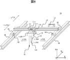
- FIG. 8 is a schematic view showing another example of the hoisting machine 10.
- the beam 15 is connected to the traveling beam 18 through the traveling device 16.
- the traveling device 16 moves the beam 15 along the traveling beam 18 in the y direction in the drawing as the traveling motor 161 rotates.
- the suspended load 30 (refer FIG. 1) hung by the trolley 11 and the hook 131 connected to the beam 15 is conveyed in the y direction in the figure. This conveyance in the y direction is referred to as traveling.
- the transport operation signal input to the transport operation unit 141 (see FIG. 1) provided in the operation terminal 14 includes a travel command signal in addition to traversing / winding. At least the travel command signal among the input transport operation signals is transmitted to the travel control unit 17 via the communication unit 143 (see FIG. 1).
- the assumed center-of-gravity distance h input to the center-of-gravity distance input unit 142 is transmitted to the travel control unit 17 in addition to the control unit 12 via the communication unit 143.
- the travel control unit 17 generates at least the transport speed command for travel based on the transport operation signal and the assumed center-of-gravity distance h, and drives the travel motor 161.
- the suspended load 30 travels in addition to traversing / winding up according to the operator's transport operation.
- the transport speed command for traversing and winding is generated in the control unit 12 and the transport speed command for travel is generated in the travel control unit 17, but the present invention is not limited to this configuration.
- control unit 12 For example, the control unit 12 generates a traversing, traveling, and winding transport speed command, and transmits at least a command related to traveling from the generated transport speed command from the control unit 12 to the travel control unit 17. May drive the traveling motor 161 based on the received conveyance speed command.
- conveyance operation signal and the assumed center-of-gravity distance h need only be transmitted to at least the control unit 12 and do not need to be transmitted to the travel control unit 17.
- FIG. 2 is a diagram schematically showing an example of pendulum parameters in the embodiment.
- the suspended load 30, the sling rope 20, the hook 131, and the rope 13 constitute a pendulum in the hoist 10.
- Equation 1 the load swing frequency Fr, which is the resonance frequency of the pendulum, is expressed by Equation 1.
- Equation 1 g is the gravitational acceleration, and the pendulum length L is the distance from the fulcrum shown in FIG.
- a conveyance speed command in which the conveyance speed command is composed only of a frequency smaller than the vibration frequency Fr is shaped by a band cutoff filter that blocks a frequency band including the vibration frequency Fr. As a result, it is possible to suppress the load swing by suppressing the component of the load swing frequency Fr from the conveyance speed command.
- the pendulum length L needs to be specified with high accuracy in order to specify the load swing frequency with high accuracy.
- the pendulum length L is a value obtained by adding the rope length L0 and the gravity center distance H.
- the rope length L0 is a distance from a fulcrum that is a position away from the pulley to the lower portion of the hook 131 when the rope 13 has the drum 1122 or the pulley. That is, the distance from the upper position of the rope 13 to the lower part of the hook 131.
- This rope length L0 is referred to as a first distance.
- the rope length L0 can be specified from the length of the rope 13 drawn from the winding drum 1122 observed by the winding encoder 1121 and the length of the hook 131.
- the center-of-gravity distance H is the distance from the lower part of the hook 131 to the suspension load core 301, and it is difficult to specify when the suspension load 30 and the sling rope 20 are various, so an example of the identification method will be described in another embodiment. To do.
- the fulcrum of the sling rope 20 means the lower part of the hook 131, not the bottom surface of the hook 131. This is because the center of gravity distance H is the distance from the fulcrum of the sling rope 20 to the center of gravity of the suspended load.
- the center-of-gravity distance H is referred to as a second distance.
- the lower portion of the hook 131 may not be a contact surface between the hook 131 and the sling rope 20. This is because the contact surface is not a fulcrum because it is the distance from the fulcrum of the sling rope 20 to the center of gravity of the suspended load.
- the rope length L0 is a unique value when it can be accurately measured, but an error described in the encoder 1121 or a value measured by the operator may be input as the rope length L0 and the calculation described later may be performed. That is, the rope length L0 may be a value including an offset in an actual measurement value.
- the assumed pendulum length l is not limited to this, and may be specified as a value obtained by adding the center-of-gravity distance h with no overlapping portion, assuming the rope length L0.
- the center-of-gravity distance H is a unique value if it can be measured accurately. Therefore, the value measured or estimated by the operator is input as the assumed center-of-gravity distance h. As the assumed center-of-gravity distance h is closer to the center-of-gravity distance H, the accuracy of load swing can be improved.
- the value obtained by adding the rope length L0 and the center of gravity distance h is the pendulum length l.
- the assumed pendulum length l may have an offset between the measured value of the rope length L0 and the center-of-gravity distance h.
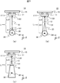
- FIG. 7 is an example of a schematic diagram showing the relationship between the suspended load 30 and the sling rope 20 and the center of gravity distance H. Comparing FIG. 7A and FIG. 7B, the center-of-gravity distance H varies depending on the sling rope 20 used even for the same suspended load 30.
- the center-of-gravity distance H changes depending on the load appearance of the suspended load 30.
- the center-of-gravity distance H varies depending on the load form of the suspended load 30 and the sling rope 20 used. For this reason, the pendulum length L cannot be specified only by the rope length L0 that the winder 10 can specify.
- the assumed center-of-gravity distance h which is the distance between the lower portion of the hook 131 and the assumed position of the suspended load 30 estimated by the operator, as shown in FIG. 2B, can be specified or measured by the operator. Is possible. Therefore, a center-of-gravity distance input unit 142 capable of inputting the assumed center-of-gravity distance h is provided.
- the assumed pendulum length l which is an estimated value of the pendulum length L, is specified by Equation 2 using the assumed center of gravity distance h input by the center of gravity distance input unit 142 and the rope length L0. That is, even when the suspended load 30 is wound up by the transport operation command, the deemed pendulum length l can be specified.
- the deemed load swing frequency fr which is an estimated value of the load swing frequency Fr, can be estimated by Equation (3).
- the load swing can be suppressed by, for example, suppressing and removing the component of the deemed load swing frequency fr from the transport speed command as described above.
- the assumed pendulum length l is estimated based on the assumed suspended load core 302 which is the estimated center of gravity position of the suspended load 30, it has an error from the pendulum length L.
- the deemed suspended load core 302 is in the occupation range of the suspended load 30. It is clear. Therefore, the assumed pendulum length l can accurately estimate the pendulum length L, and the effect of suppressing load swing is improved.
- the hoisting machine 10 may have a function of judging the validity of the input assumed center-of-gravity distance h and notifying the operator. For example, when a negative distance is input as the assumed center-of-gravity distance h, or the obtained assumed pendulum length l is the height from the floor surface (40 in FIG. 3) of the hoisting drum 1122 input in advance. When the distance is greater than a certain fulcrum height (K in FIG. 3), it can be determined that the deemed center of gravity 302 is not within the occupation range of the suspended load 30, and the operator is notified.
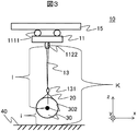
- FIG. 3 is a diagram illustrating an example of parameters that can be input by the other center-of-gravity distance input unit 142.
- the input to the center-of-gravity distance input unit 142 is not limited to the assumed center-of-gravity distance h.
- the assumed pendulum length l may be input as the assumed center-of-gravity distance.
- the assumed center-of-gravity distance h is obtained from the inputted assumed pendulum length l and rope length L0.
- the assumed center-of-gravity height i which is the height of the center of gravity 302 from the floor surface 40 may be input to the center-of-gravity distance input unit 142 as the assumed center-of-gravity distance.
- the assumed center-of-gravity distance h is obtained from Equation 4 using the input height i of the assumed center of gravity 302 and the fulcrum height K.
- the input to the center-of-gravity distance input unit 142 may be the input of the assumed center-of-gravity distance h and the distance at which the assumed center-of-gravity distance h can be calculated, for example, the assumed pendulum length and the assumed center-of-gravity height i in a ratio to a predetermined distance.
- the predetermined distance may be a distance that can be correctly specified, for example, the rope length L0, the fulcrum height K, the height from the floor surface 40 below the hook 131 (K-L0), or the like.
- the assumed center-of-gravity distance h can be calculated using the input ratio and a predetermined distance.
- the rope length L0 is considered and the center-of-gravity distance h is divided with reference to the lower part of the hook 131, but this is not restrictive.
- the assumed pendulum length l and the assumed center-of-gravity distance h can be calculated from the distance from the suspension load core 302 and the rope length L0 as the reference position. It is.
- the deemed pendulum length l can be calculated from the length of the hook 131, the rope length L0, and the deemed center of gravity distance h.
- FIG. 4 is a diagram schematically showing an example of a marker for assisting operator input.
- the winding machine 10 may have a marker 132 for assisting input to the center-of-gravity distance input unit 142.
- the center-of-gravity distance input unit 142 is configured to input the deemed center-of-gravity distance h based on the distance between the markers 132 or the number of markers 132. Thereby, it is possible to reduce variations in accuracy of the assumed center-of-gravity distance h due to individual differences among operators.
- the number and position of the markers are regarded as the center-of-gravity distance h
- the measured center of gravity distance H is regarded and input as the center of gravity distance h, it is easy to reduce the vibration of the load.
- the marker 132 can be realized, for example, by coloring the rope 13 and the hook 131 at regular intervals. That is, the color is different from that of the rope 13. Further, the entire rope 13 can be a ground color, and the marker 131 can be colored in a color different from the ground color of the rope 13. The entire rope 13 may be colored, and a part of the rope 13 may be used as the marker 132 as a background color. Moreover, it is good also as not only coloring but a different shape.
- the input unit 142 may be provided with a display unit so that the input center-of-gravity distance is displayed.
- the input means of the input unit 142 may be a touch panel, a push button, or a potentiometer (volume).
- the push button is provided with an addition button and a subtraction button so that the number that the operator can see can be input, so that the center of gravity distance h can be specified and input work can be facilitated using the operator's marker.
- the potentiometer may change its value stepwise. In this case, if the potentiometer stage corresponds to the number of markers, the input becomes easy. By displaying the number of markers around the volume, the number of markers can be easily input.
- the hoisting machine is not limited to the above embodiment.
- the communication unit 143 may be wired communication instead of wireless communication.
- the center-of-gravity distance input unit 142 may be provided in an operation terminal 14 that is different from the transport operation unit 141.
- the input to the gravity center distance input unit 142 may be performed by an input person different from the operator.
- the assumed center-of-gravity distance h is a value measured or specified by the operator and input to the input means or an estimated value of the center-of-gravity distance specified by calculating or correcting the input value. Therefore, the assumed center-of-gravity distance does not mean a strict value that is unique to the center-of-gravity distance H, but an estimated value of the center-of-gravity distance H. The same applies to the pendulum length l, the assumed center of gravity height i, the assumed suspended load core, and the like. Furthermore, a predetermined value of the assumed center of gravity distance h that may be used when the operator does not input the assumed center of gravity distance h may be set.
- the estimation accuracy of the pendulum length L can be increased.
- the load can be reduced and the runout can be reduced.
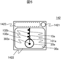
- FIG. 5 is a diagram illustrating an example of another configuration of the centroid distance input unit 142.
- the center-of-gravity distance input unit 142 includes a camera 1421, a display input unit 1422, and a calculation unit 1423.
- the display input unit 1422 displays an image acquired by the operator with the camera 1421.
- the calculation unit 1423 calculates the assumed center-of-gravity distance h based on the image.
- the calculated assumed center-of-gravity distance h is sent to the control unit 12 via the communication unit 143 and is used to determine the conveyance speed command.
- a rope (captured image) 13a Is the image displayed on the display input unit 1422.
- the calculation unit 1423 specifies the suspended load (captured image) 30a by image processing
- the only suspended load core (calculation result) 302a in the image can be estimated.
- the suspended load core (calculation result) 302a can be estimated. If images from multiple directions are used, the accuracy of the estimated deemed suspended load core (calculation result) 302a increases.
- the center-of-gravity distance input unit 142 may have a function of assisting the arithmetic processing by the arithmetic unit 1423.
- the operator can assist the image processing and the assumed suspended load core (calculation result) 302a by selecting the closest candidate.
- the deemed suspended load core (calculation result) 302a may be displayed on the display input unit 1422.
- the operator can confirm the position of the deemed suspended load core (calculation result) 302a in the image.
- the operator may adjust the position of the deemed suspended load core (calculation result) 302a displayed on the display input unit 1422. This can be realized by the display input unit 1422 being a touch panel.
- the operator may input the assumed suspension load center 302a estimated in the image by the operator to the display input unit 1422 without using image processing. This can be realized by the display input unit 1422 being a touch panel.
- the deemed center-of-gravity distance h in the real space is obtained by, for example, the following computation of the computation unit 1423.
- the distance between the identified deemed suspended load core (calculation result) 302a and the marker (hook captured image) 132a can be obtained in the image as a distance in pixel units.
- the interval between the markers (captured images) 132b can be obtained in the image as a pixel unit distance.
- the interval between the markers 132 in the real space and the distance between the marker 132 (in the image, corresponding to the marker (hooked image) 132a) and the lower portion of the hook 131 are input in advance. .
- the distance between the assumed suspended load core (calculation result) 302a and the marker (hook captured image) 132a is in real space. It can be converted into the distance between the non-continuous hanging load core 302 and the marker 132 (arranged on the hook). Further, the assumed center-of-gravity distance h in the real space can be calculated using the distance between the marker 132 (arranged on the hook) input in advance and the lower portion of the hook 131.
- the computing unit 1423 obtains the center-of-gravity distance h only in the real space using the assumed suspended load core (calculation result) 302a specified in the image.
- FIG. 6 is a diagram illustrating an example of another configuration of the centroid distance input unit 142.
- the operator inputs the ID of the suspended load 30 that has been conveyed or has been conveyed to the suspended load ID input unit 1425.
- the assumed center-of-gravity distance h specified by the method described in Example 1 or Example 2 is input to the center-of-gravity distance display input unit 1426.
- the operator gives a registration command for the suspended load 30 by pressing a registration button 1427 or the like.
- the center-of-gravity distance input unit 142 stores the suspended load ID and the assumed center-of-gravity distance h in the memory 1424.
- the assumed center-of-gravity distance h read from the memory 1424 is transmitted to the control unit 12 via the communication unit 143.
- the operator inputs the ID of the suspended load 30 to be transferred to the suspended load ID input unit 1425 and gives a read instruction of the suspended load 30 by pressing the read button 1428 or the like.
- the center-of-gravity distance input unit 142 reads the deemed center-of-gravity distance h corresponding to the input suspended load ID from the memory 1424 and transmits it to the control unit 12 via the communication unit 143.
- the assumed center-of-gravity distance h read from the memory 1424 may be displayed on the center-of-gravity distance display input unit 1426.
- the registered or read deemed center-of-gravity distance h may be sent to the control unit 12 via the communication unit 143 by giving a transmission command or the like according to an operator instruction.
- the form of the suspended load ID input unit 1425 is not limited to the input of the ID number as long as the suspended load 30 can be specified.
- the name of the suspended load 30 may be used.
- the suspended load ID input unit 1425 may be in the form of a barcode reader.
- the center-of-gravity distance input unit 142 has the configuration of FIG. 5, the suspended load ID may include an image. From the suspended load ID recorded in the memory 1424 using the image of the suspended load 30, It may be a form in which a similar suspended load 30 is image-searched and displayed on the operator for selection.
- the center-of-gravity distance h can be recorded only for each combination of the suspended load 30 and the sling rope 20. Thereby, when using the various sling ropes 20 with respect to the same suspended load 20, it becomes possible to specify the more accurate assumed pendulum length l.
- the operator can specify the type of the sling rope 20 to be used by displaying the recorded type of the sling rope 20.
Landscapes
- Engineering & Computer Science (AREA)
- Mechanical Engineering (AREA)
- Automation & Control Theory (AREA)
- Control And Safety Of Cranes (AREA)
Abstract
自走手段により搬送されるトロリと、トロリに搭載された巻上げモータと、巻上げモータに取り付けられた巻上げドラムと、巻上げドラムに取り付けられたロープと、ロープに取り付けられたフックと、トロリの搬送速度を特定する制御部とを有し、制御部は所定位置とフックに吊り下げられた吊荷の重心位置との間の重心距離に基づいてトロリの搬送速度を特定する。
Description
本発明は、巻上げ機に関する。
巻上げ機においては、安全で効率的な吊荷搬送のために、搬送時の荷振れの低減が求められている。この荷振れ低減のための技術として、ロープに吊られた吊荷を振子とみなし、この振子の振れ、すなわち荷振れのモデルに基づいて、搬送速度を制御する荷振れ抑制制御技術が知られている。
この荷振れ抑制制御は、大きくフィードフォワード制御とフィードバック制御に分けられる。フィードフォワード制御は、荷振れのモデルに基づいて搬送速度指令を決定することで荷振れを抑制する方法である。
フィードバック制御は、荷振れをリアルタイムで検出もしくは推定してフィードバックして搬送速度指令を決定することで、荷振れを抑制する方法である。また、2自由度荷振れ抑制制御では、フィードフォワード制御とフィードバック制御を併せて行う。
フィードバック制御は、一般に、荷振れモデルの誤差に対応できるが、フィードフォワード制御と比べて応答が遅い。フィードフォワード制御は、一般に、フィードバック制御と比べて応答が速いが、荷振れモデルの誤差に対応できない。つまり、精度の高い荷振れモデルを求めることができれば、応答が速く、且つ、精度の高い荷振れ抑制が可能となり、2自由度制御においてもその荷振れ抑制の効果が向上する。
ここで、荷振れモデルには、振子の振れ周期を推定するために、振れの支点から振子重心までの長さである振子長さが必要である。一般に、この振子長さとして、巻上げドラムからフックまでのロープ長を用いる。しかし、吊荷はフック下に吊られることから、振子長さはロープ長とは異なる。この振子長さを精度よく求める技術として、特許文献1や特許文献2がある。
特許文献1では、吊荷の置かれた床に配置された荷重センサによって吊荷の離床を検出し、トロリの床面高さと離床時のロープ長から、フック下部から吊荷下端までの距離を求める技術が記載されている。
特許文献2では、吊荷なしの場合は振子長さをロープ長とし、吊荷のある場合は予め求めた補正値とロープ長から振子長さを求める技術が記載されている。
特許文献1に記載された技術によれば、巻上げドラムから吊荷下端の距離を振子長さと規定できる。これにより、ロープ長を振子長さとする場合と比べ、精度の高い荷振れ抑制が可能となる。しかしながら、吊荷の重心と吊荷下端の位置は異なるため、荷振れモデルは誤差をもち、荷振れが残る可能性がある。
特許文献2に記載された技術によれば、予め求めた吊荷の重心位置を用いて振子長さを補正する。これにより、ロープ長を振子長さとする場合と比べ、精度の高い荷振れ抑制が可能となる。しかしながら、吊荷の有無のみで補正値を変えるため、多様な吊荷に応じることができない。
本発明の目的は、巻上げ機において荷振れを低減させることにある。
本発明の一態様の巻上げ機は、自走手段により搬送されるトロリと、前記トロリに搭載された巻上げモータと、前記巻上げモータに取り付けられた巻上げドラムと、前記巻上げドラムに取り付けられたロープと、前記ロープに取り付けられたフックと、前記トロリの搬送速度を特定する制御部と、を有し、前記制御部は、所定位置と前記フックに吊り下げられた荷の重心位置との間の重心距離に基づいて、前記トロリの搬送速度を特定することを特徴とする。
本発明の一態様によれば、巻上げ機において荷振れを低減させることができる。
以下、実施例について図面を用いて説明する。
本発明は、主にロープで吊上げた荷を搬送する巻上げ機に関し、特に荷振れのモデルに基づいて搬送速度を決定することで搬送時の荷振れを抑制する巻上げ機に関する。他にも、同様に吊荷を搬送するクレーンについても適用可能である。
図1は、実施例における巻上げ機の構成の一例を概略的に示す図である。
図1において、搬送対象である吊荷30は、玉掛けロープ20によってフック131に吊り下げられる。フック131は、ロープ13によって巻上げドラム1122に吊り下げられる。ここで、吊荷30は玉掛けロープ20を介せず、フック131に直接吊り下げられる構成でもよい。
巻上げドラム1122は、巻上げシャフト1123によって巻上げモータ112および巻上げエンコーダ1121と連結され、トロリ11に配置される。これにより、巻上げモータ112が回転することで、ロープ13は巻上げもしくは巻下げられ、吊荷30は図中z方向に搬送できる。このz方向の搬送を、巻上げと称する。
横行輪1111は、横行シャフト1112を介して横行モータ111と連結され、トロリ11に配置される。また、横行モータ111の回転により、横行輪1111は、ビーム15上を回転し、駆動力を発生できるよう配置される。これにより、横行モータ111が回転することで、トロリ11および吊荷30はビームに沿って図中x方向に搬送できる。
このx方向の搬送を、横行と称する。
このx方向の搬送を、横行と称する。
搬送操作部141は、操作端末14に備えられ、オペレータによって横行もしくは巻上げ、またはその両方の指令である搬送操作信号を入力される。入力された搬送操作信号は、通信部143を介して制御部12に通信される。
重心距離入力部142は、操作端末14に備えられ、オペレータによって、後述するみなし重心距離hを入力される。入力されたみなし重心距離hは、通信部143を介して制御部12に通信される。みなし重心距離hは、オペレータによって入力された所定の重心距離である。
ここで、重心距離入力部142は、搬送操作部141と同一の操作端末14に備えられる必要はなく、それぞれ別の操作端末14に備えられてもよい。
制御部12は、搬送操作信号およびみなし重心距離hに基づいて搬送速度指令を生成し、横行モータ111もしくは巻上げモータ112、またはその両方を駆動する。これにより、オペレータの搬送操作に応じて、吊荷30は横行し、巻上げられる。同様に、吊荷30は、巻上げ後に横行でき、また、横行中に巻上げ、巻上げ中に横行できる。
なお、吊荷30および玉掛けロープ20は、搬送対象であり、巻上げ機10の構成要素ではない。また、吊荷30の吊下げに用いる治具は、玉掛けロープ20に限るものではなく、また無くてもよい。
図8は、巻上げ機10の別の例を示す概略図である。
図8において、ビーム15は走行装置16を介して走行ビーム18と接続されている。走行装置16は、走行モータ161が回転することで、ビーム15を走行ビーム18に沿って図中y方向に移動させる。これにより、ビーム15に接続されたトロリ11およびフック131に吊り下げられた吊荷30(図1参照)は、図中y方向に搬送される。このy方向の搬送を、走行と称する。
操作端末14に備えられた搬送操作部141(図1参照)に入力される搬送操作信号は、横行/巻上げに加えて走行の指令信号を有する。入力された搬送操作信号のうち少なくとも走行指令信号は、通信部143(図1参照)を介して走行制御部17に送信される。
また、重心距離入力部142(図1参照)に入力されたみなし重心距離hは、通信部143を介して制御部12に加えて走行制御部17に送信される。走行制御部17は、搬送操作信号およびみなし重心距離hに基づいて少なくとも走行に掛る前記搬送速度指令を生成し、走行モータ161を駆動する。これにより、オペレータの搬送操作に応じて、吊荷30(図1参照)は横行/巻上げに加えて走行される。
なお、ここでは、制御部12において横行、巻上げの前記搬送速度指令を生成し、走行制御部17において走行の搬送速度指令を生成するよう説明したが、この構成に限るものではない。
例えば、制御部12において横行、走行、巻上げの搬送速度指令を生成し、生成した前記搬送速度指令のうち少なくとも走行にかかる指令を制御部12から走行制御部17に送信して、走行制御部17は受信した搬送速度指令に基づいて走行モータ161を駆動してもよい。この場合、搬送操作信号およびみなし重心距離hは、少なくとも制御部12に送信されればよく、走行制御部17に送信される必要はない。
図2は、実施例における振子のパラメータの一例を概略的に示す図である。
図2において、吊荷30および、玉掛けロープ20、フック131、ロープ13は、巻上げ機10において振子を構成している。
横行もしくは走行時にトロリ11に印加される加速度により、巻上げドラム1122を支点として吊荷30が荷振れを生じる。この時、前記振子の共振周波数である荷振れ周波数Frは、数1となる。数1において、gは重力加速度であり、振子長さLは図2(a)に示す支点から吊荷重心301までの距離である。

搬送速度指令が荷振れ周波数Frの成分をもたなければ、荷振れは励起されない。そこで、例えば、搬送速度指令を荷振れ周波数Frより小さい周波数のみで構成する搬送速度指令を、荷振れ周波数Frを含む周波数帯域を遮断する帯域遮断フィルタで整形する。これにより、搬送速度指令から荷振れ周波数Frの成分を抑制することで、荷振れの抑制が可能となる。
したがって、制御部12において荷振れ抑制を可能とする搬送速度指令を生成するためには、荷振れ周波数Frを精度よく特定する必要がある。重力加速度gが巻上げ機10の使用環境で一定とすると、荷振れ周波数を精度よく特定するためには、振子長さLを精度よく特定する必要がある。
ここで、図2(a)に示す通り、前記振子長さLは、ロープ長L0と重心距離Hとを加算した値である。前記ロープ長L0は、ロープ13がドラム1122または滑車を有する場合には滑車から離れる位置である支点からフック131下部までの距離である。すなわち、ロープ13の上部の位置からフック131下部までの距離である。このロープ長L0を第1の距離と呼ぶ。
ロープ長L0は、巻上げエンコーダ1121で観測した巻上げドラム1122より引き出されたロープ13の長さと、フック131の長さから特定できる。
重心距離Hは、フック131下部から吊荷重心301までの距離であり、吊荷30や玉掛けロープ20が多様である場合は特定が困難であるため、他の実施例で特定方法の例について説明する。
ここで、フック131の下部の一例について説明する。フック131とフック131に吊り下げられる玉掛けロープ20との接触面である。つまり。フック131の底面ではなく、玉掛ロープ20の支点がフック131の下部を意味する。重心距離Hは、玉掛けロープ20の支点から吊荷の重心までの距離だからである。また、この重心距離Hを第2の距離と呼ぶ。なお、玉掛ロープ20の太さによっては、フック131の下部は、フック131と玉掛ロープ20の接触面でない場合もある。これは、玉掛けロープ20の支点から吊荷の重心までの距離であるため、接触面が支点にならないためである。
ロープ長L0は正確に測定できると一意の値となるが、エンコーダ1121で測定した値の誤差やオペレータが測定した値をロープ長L0して入力して後述の演算を行っても良い。すなわち、ロープ長L0には実測値にオフセットを含めた値であってもよい。これに限らず、みなし振子長さlは、ロープ長L0とみなし重心距離hが重複部分を有さずに加算された値として特定されればよい。
ここで、重心距離Hは正確に測定できると、一意の値となる。そのため、オペレータが測定あるいは推定した値を、みなし重心距離hとして入力する。みなし重心距離hが重心距離Hに近いほど、荷振れの精度を向上させることができる。
上記したロープ長L0と重心距離hを加算した値をみなし振子長さlである。みなし振子長さlは、ロープ長L0の実測値と、重心距離hにオフセットをもたせてもよい。
ここで、図7を参照して、吊荷30や玉掛けロープ20による重心距離Hの違いを説明する。
図7は、吊荷30および玉掛けロープ20と重心距離Hとの関係を示す概略図の例である。図7(a)と図7(b)を比較すると、同一の吊荷30であっても、用いる玉掛けロープ20によって前記重心距離Hは変わる。
また、図7(b)と図7(c)を比較すると、吊荷30の荷姿によって重心距離Hは変わる。このように、重心距離Hは、吊荷30の荷姿や用いる玉掛けロープ20によって変わる。このため、振子長さLは巻上げ機10が特定可能なロープ長L0のみでは特定できない。
ここで、図2において、巻上げ機10のオペレータが、吊荷重心301の位置を推定する方法について説明する。つまり、図2(b)に示す、フック131下部とオペレータが推定した吊荷30の重心位置であるみなし吊荷重心302との距離であるみなし重心距離hは、オペレータによって特定または実測することが可能である。そこで、みなし重心距離hを入力可能な重心距離入力部142を設ける。
重心距離入力部142で入力されたみなし重心距離hと、ロープ長L0を用いて、振子長さLの推定値であるみなし振子長さlを数2より特定する。つまり、搬送操作指令によって吊荷30が巻上げられた場合においても、みなし振子長さlは特定可能である。

特定したみなし振子長さlを用いて、荷振れ周波数Frの推定値であるみなし荷振れ周波数frは、数3により推定可能である。

このみなし荷振れ周波数frが精度よく荷振れ周波数Frを推定されていれば、前述の通り、例えば、搬送速度指令からみなし荷振れ周波数frの成分を抑制し除去することにより荷振れが抑制できる。
ここで、みなし振子長さlは、吊荷30の推定された重心位置である、みなし吊荷重心302に基づいて推定されているため、振子長さLとは誤差をもつ。しかしながら、みなし振子長さlとしてロープ長L0を用いる場合や、みなし振子長さlとして支点から吊荷30下端を用いる場合と比較して、みなし吊荷重心302が吊荷30の占有範囲にあることは明らかである。よって、みなし振子長さlは振子長さLを精度よく推定でき、荷振れ抑制の効果が向上する。
ここで、巻上げ機10は、入力されたみなし重心距離hの妥当性を判断してオペレータに通知する機能を有していてもよい。例えば、みなし重心距離hに負の距離が入力された場合や、求められた前記みなし振子長さlが、あらかじめ入力された巻上ドラム1122の床面(図3中40)からの高さである支点高さ(図3中K)よりも大きな距離である場合などは、みなし重心302が吊荷30の占有範囲にないと判断でき、オペレータに通知する。
図3は、他の重心距離入力部142で入力可能なパラメータの一例を示す図である。
重心距離入力部142への入力は、みなし重心距離hに限るものではなく、例えば、みなし重心距離として、みなし振子長さlを入力してもよい。この場合、入力されたみなし振子長さlとロープ長L0からみなし重心距離hが求められる。
また、例えば、床面40からのみなし重心302の高さであるみなし重心高さiを、みなし重心距離として、重心距離入力部142に入力してもよい。この場合、入力されたみなし重心302の高さiと支点高さKを用いて数4よりみなし重心距離hが求められる。

また、重心距離入力部142への入力は、みなし重心距離hおよびみなし重心距離hを算出可能な距離、例えば、みなし振り子長さやみなし重心高さiを、所定の距離に対する比率で入力してもよい。所定の距離は、正しく特定可能な距離、例えば、前記ロープ長L0や、支点高さK、フック131下部の床面40からの高さ(K-L0)などにすればよい。入力された比率と、所定の距離を用いて、みなし重心距離hは算出できる。
また例えば、実施例では、ロープ長L0とみなし重心距離hをフック131下部を基準として分けているが、この限りではない。例えば、基準位置をフック下部から所定の距離だけ離れた位置とした場合、基準位置とみなし吊荷重心302との距離とロープ長L0とから、みなし振子長さlおよびみなし重心距離hは算出可能である。例えば、基準位置をフック131の上部とした場合、フック131の長さとロープ長L0、みなし重心距離hから、みなし振子長さlは算出可能である。
図4は、オペレータ入力を補助するマーカの一例を概略的に示す図である。
巻上げ機10は、重心距離入力部142への入力を補助するためのマーカ132を有してもよい。例えば、重心距離入力部142は、マーカ132間の距離又はマーカ132の個数に基づいて、前記みなし重心距離hを入力する構成とする。これにより、オペレータの個人差によるみなし重心距離hの精度ばらつきを低減できる。
また、マーカの数や位置をみなし重心距離hとする場合には、重心距離Hを測定する場合に比べて、オペレータが簡便に値を入力することが可能となり、ホイストの運用効率が向上する。一方、マーカの数や位置をみなし重心距離hとする場合に比べて、実測した重心距離Hをみなし重心距離hとして入力する場合には、荷振れを低減させやすくなる。
マーカ132は、例えば、ロープ13やフック131を一定間隔で着色するなど実現できる。つまり、ロープ13とは異なる色である。また、ロープ13全体を地色とし、マーカ131にロープ13の地色とは異なる色に着色することができる。ロープ13全体を着色し、一部を地色としてマーカ132としてもよい。また、着色に限らず、異なる形状としてもよい。
入力部142には、表示部を設け、入力された重心距離が表示されるようにしてもよい。また、入力部142の入力手段は、タッチパネル、押し釦、ポテンショメータ(ボリューム)であってもよい。
押し釦は、加算ボタン、減算ボタンを設けることで、オペレータが目視できた数を入力するよう設定することで、オペレータのマーカを用いて重心距離hの特定と、入力作業が容易となる。
また、ポテンショメータ(ボリューム)は階段状に値が変化するものであってもよい。この場合は、マーカの数とのポテンショメータの段階が対応する関係であれば入力が容易となる。ボリューム周辺にマーカの数を表示することで、マーカの数を容易に入力することができる。
ここで、巻上げ機は、上記実施例に限るものではない。例えば、通信部143は無線通信でなく、有線通信であってもよい。また例えば、重心距離入力部142は、搬送操作部141とは別の操作端末14に備えられてもよい。また例えば、重心距離入力部142への入力は、オペレータと別の入力者によって行われてもよい。
ここで、みなし重心距離hとは、オペレータによって測定もしくは特定され入力手段に入力された値または入力された値を演算もしくは補正することによって特定される重心距離の推定値である。したがって、みなし重心距離とは重心距離Hの一意となる厳密な値を意味するものではなく、重心距離Hの推定値であることを意味する。他のみなし振子長さl、みなし重心高さi、みなし吊荷重心等も同様である。さらには、オペレータがみなし重心距離hを入力しない場合などに使用可能なみなし重心距離hの所定値を設定してもよい。これにより、重心距離hの所定値をよく用いられる吊荷条件に基づいて設定しておくなどにより、オペレータがみなし重心距離hを入力することのない場合にも、振子長さLの推定精度を向上でき、荷振れが低減できる。
図5は、重心距離入力部142の別の構成の一例を示す図である。
図5において、重心距離入力部142は、カメラ1421と、表示入力部1422及び演算部1423で構成される。表示入力部1422は、オペレータがカメラ1421で取得した画像を表示する。演算部1423は、画像に基づいて、みなし重心距離hを演算する。演算されたみなし重心距離hは、通信部143を介して制御部12に送られて、前記搬送速度指令の決定に用いられる。
図5において、ロープ(撮像画像)13aおよび、フック(撮像画像)131a、マーカ(フック、撮像画像)132a、マーカ(撮像画像)132b、玉掛けロープ(撮像画像)20a及び吊荷(撮像画像)30aは、表示入力部1422に表示された前記画像である。
例えば、演算部1423が画像処理によって吊荷(撮像画像)30aを特定することで、前記画像内のみなし吊荷重心(演算結果)302aは推定可能である。一方向からの前記画像のみを用いる場合は、例えば、吊荷30の密度や奥行きを均一とすればみなし吊荷重心(演算結果)302aが推定できる。多方向からの画像を用いれば、推定されるみなし吊荷重心(演算結果)302aの精度は上がる。
また、重心距離入力部142は、演算部1423による演算処理を補助する機能を有してもよい。例えば、吊荷30の模式的な形状の候補を有しており、オペレータが最も近い候補を選択することで、画像処理およびみなし吊荷重心(演算結果)302aを補助できる。
ここで、みなし吊荷重心(演算結果)302aは、表示入力部1422に表示してもよい。これにより、オペレータが前記画像内におけるみなし吊荷重心(演算結果)302aの位置を確認可能となる。さらには、オペレータが表示入力部1422に表示されたみなし吊荷重心(演算結果)302aの位置を調整できるよう構成してもよい。これは、表示入力部1422がタッチパネルになっているなどで実現できる。
また、みなし吊荷重心(演算結果)302aは、画像処理を用いることなく、オペレータが前記画像において推定したみなし吊荷重心302aを、オペレータが表示入力部1422に入力してもよい。これは、表示入力部1422がタッチパネルになっているなどで実現できる。特定されたみなし吊荷重心(演算結果)302aを用いて、実空間での前記みなし重心距離hは、例えば、演算部1423の以下演算により求められる。
特定されたみなし吊荷重心(演算結果)302aとマーカ(フック撮像画像)132aとの距離は、画素単位の距離として前記画像内で求めることができる。また、同様にマーカ(撮像画像)132bの間隔は、画素単位の距離として前記画像内で求めることができる。ここで、実空間でのマーカ132の間隔および、マーカ132の内フックに配置したもの(画像内、マーカ(フック撮像画像)132aに対応)とフック131下部との距離は、あらかじめ入力されている。
画素単位のマーカ(撮像画像)132bの間隔と、実空間でのマーカ132の間隔を用いて、みなし吊荷重心(演算結果)302aとマーカ(フック撮像画像)132aとの距離は、実空間でのみなし吊荷重心302とマーカ132(フックに配置したもの)との距離に変換できる。さらに、あらかじめ入力されているマーカ132(フックに配置したもの)とフック131下部との距離を用いて、実空間での前記みなし重心距離hは演算できる。
以上の通り、画像内で特定されたみなし吊荷重心(演算結果)302aを用いて、実空間でのみなし重心距離hは、演算部1423により求められる。
図6は、重心距離入力部142の別の構成の一例を示す図である。
図6において、オペレータは、搬送するもしくは搬送した吊荷30のIDを吊荷ID入力部1425に入力する。吊荷30に対して、実施例1または実施例2に前述の方法で特定されたみなし重心距離hを重心距離表示入力部1426に入力する。オペレータが、登録ボタン1427を押すなどで、吊荷30の登録指令を与える。これにより、重心距離入力部142は、吊荷IDおよびみなし重心距離hをメモリ1424に記憶する。そして、メモリ1424から読み出されたみなし重心距離hは通信部143を介して制御部12に送信される。
オペレータが、搬送する吊荷30のIDを吊荷ID入力部1425に入力し、読出ボタン1428を押すなどで吊荷30の読出し指令を与える。これにより、重心距離入力部142は、入力された吊荷IDに対応する前記みなし重心距離hをメモリ1424から読み出し、通信部143を介して制御部12に送信される。この時、メモリ1424から読み出した前記みなし重心距離hは、重心距離表示入力部1426に表示してもよい。
ここで、登録もしくは読み出されたみなし重心距離hが通信部143を介して制御部12に送られるのは、送信指令を与えるなどで、オペレータ指示によって行われてもよい。
また、吊荷ID入力部1425の形態は、吊荷30が特定可能であればよく、ID番号の入力に限らない。例えば、吊荷30の名称であってもよい。また例えば、吊荷30を管理するバーコードなどが貼付されている場合、吊荷ID入力部1425はバーコードリーダの形態をもてばよい。また、重心距離入力部142が、図5の構成を併せもつ場合、前記吊荷IDは画像を含んでもよく、吊荷30の画像を用いて、メモリ1424内に記録された吊荷IDから、同様の吊荷30を画像検索して、オペレータに表示して選択される形態でもよい。
さらに、メモリ1424に吊荷IDおよびみなし重心距離hに加えて、別の情報を併せて記録してもよい。例えば、別の情報として、使用した玉掛けロープ20の種類を記録することで、吊荷30と玉掛けロープ20の組み合わせ毎のみなし重心距離hを記録できる。これにより、同一の吊荷20に対して多種の玉掛けロープ20を使用する際に、より精度のよいみなし振子長さlを特定可能となる。
また、読出指令により吊荷IDで吊荷30を特定した際に、記録された玉掛けロープ20の種類を表示することで、オペレータは使用すべき玉掛けロープ20の種類を特定できる。
10 巻上げ機
11 トロリ
111 横行モータ
1111 横行輪
1112 横行シャフト
112 巻上げモータ
1121 巻上げエンコーダ
1122 巻上げドラム
1123 巻上げシャフト
12 制御部
13 ロープ
131 フック
132 マーカ
14 操作端末
141 搬送操作部
142 重心距離入力部
1421 カメラ
1422 表示入力部
1423 演算部
1424 メモリ
1425 吊荷ID入力部
1426 重心距離表示入力部
1427 登録ボタン
1428 読出ボタン
143 通信部
15 ビーム
16 走行装置
161 走行モータ
17 走行制御部
18 走行ビーム
20 玉掛けロープ
30 吊荷
301 吊荷重心
302 みなし吊荷重心
40 床面
11 トロリ
111 横行モータ
1111 横行輪
1112 横行シャフト
112 巻上げモータ
1121 巻上げエンコーダ
1122 巻上げドラム
1123 巻上げシャフト
12 制御部
13 ロープ
131 フック
132 マーカ
14 操作端末
141 搬送操作部
142 重心距離入力部
1421 カメラ
1422 表示入力部
1423 演算部
1424 メモリ
1425 吊荷ID入力部
1426 重心距離表示入力部
1427 登録ボタン
1428 読出ボタン
143 通信部
15 ビーム
16 走行装置
161 走行モータ
17 走行制御部
18 走行ビーム
20 玉掛けロープ
30 吊荷
301 吊荷重心
302 みなし吊荷重心
40 床面
Claims (17)
- 自走手段により搬送されるトロリと、前記トロリに搭載された巻上げモータと、前記巻上げモータに取り付けられた巻上げドラムと、前記巻上げドラムに取り付けられたロープと、前記ロープに取り付けられたフックと、前記トロリの搬送速度を特定する制御部と、
を有し、
前記制御部は、所定位置と前記フックに吊り下げられた吊荷の重心位置との間の重心距離に基づいて、前記トロリの搬送速度を特定することを特徴とする巻上げ機。 - 前記所定位置は、前記フックの下部であり、
前記重心距離は、前記フックの下部と前記吊荷の重心位置との間の重心距離の推定値とすることを特徴とする請求項1に記載の巻上げ機。 - 前記所定位置は、前記フックの下部から所定の距離だけ離れた基準位置であり、
前記重心距離は、前記基準位置と前記吊荷の重心位置との間の重心距離の推定値とすることを特徴とする請求項1に記載の巻上げ機。 - 前記所定位置は、床面位置であり、
前記重心距離は、前記床面位置と前記吊荷の重心位置との間の重心距離の推定値とすることを特徴とする請求項1に記載の巻上げ機。 - 前記所定位置は、前記巻上げドラムの支点位置であり、
前記重心距離は、前記支点位置と前記吊荷の重心位置との間の重心距離の推定値とすることを特徴とする請求項1に記載の巻上げ機。 - 前記所定位置は、前記フックの上部であり、
前記重心距離は、前記フックの上部と前記吊荷の重心位置との間の重心距離の推定値とすることを特徴とする請求項1に記載の巻上げ機。 - 前記制御部は、
前記ロープの長さと前記重心距離とを用いて、前記巻上げドラムの支点位置と前記吊荷の重心位置との間の振子長さの推定値を特定し、
前記特定した前記振子長さの推定値を用いて、前記吊荷の荷振れ周波数の推定値である荷振れ周波数を特定し、
前記トロリの前記搬送速度から前記荷振れ周波数の成分を除去することを特徴とする請求項1に記載の巻上げ機。 - 前記重心距離の推定値が設定可能であることを特徴とする請求項1に記載の巻上げ機。
- 前記重心距離を入力する重心距離入力部を有することを特徴とする請求項1に記載の巻上げ機。
- 前記重心距離の推定値の既定値が設定可能であり、前記重心距離の入力がない場合は、該既定値を用いることを特徴とする請求項9に記載の巻上げ機。
- 前記重心距離入力部は、前記トロリの前記搬送速度の指令を与える搬送操作部と、前記制御部に前記重心距離と前記搬送速度を送信する通信部を有する操作端末に備えられていることを特徴とする請求項9に記載の巻上げ機。
- 前記ロープは、所定間隔のマーカを有することを特徴とする請求項9に記載の巻上げ機。
- 前記マーカは、前記ロープとは異なる色または形状であることを特徴とする請求項12に記載の巻上げ機。
- 前記重心距離入力部は、撮像装置と演算部を有し、
前記撮像装置は、前記複数のマーカを有する前記ロープと、前記フックと、前記フックに吊り下げられた前記吊荷を撮像し、
前記演算部は、前記撮像装置で撮像した画像に基づいて前記重心距離を特定し、
前記通信部は、特定された前記重心距離を前記制御部に送信することを特徴とする請求項12に記載の巻上げ機。 - 前記重心距離入力部は、
前記吊荷のIDを入力する吊荷ID入力部と、
前記重心距離を入力する入力部と、
前記吊荷のIDと前記重心距離を対応させて記憶する記憶部を、有し、
前記吊荷ID入力部から入力された前記吊荷のIDに対応する前記重心距離を前記記憶部から読み出して、前記通信部を介して、前記読み出した前記重心距離を前記制御部に送信することを特徴とする請求項9に記載の巻上げ機。 - 前記吊荷は、保持手段によって前記ロープに吊り下げられ、
前記記憶部に、前記吊荷と前記保持手段の種類の組み合わせ毎に前記重心距離を記憶し、
前記記憶部から、前記吊荷と前記治具の組み合わせに対応する前記重心距離を読み出し
て、前記通信部を介して、前記読み出した前記重心距離を前記制御部に送信することを特徴とする請求項15に記載の巻上げ機。 - 前記記憶部は、前記保持手段の種類として、前記フックと前記吊荷の間に設けられた玉掛けロープの種類を記憶することを特徴とする請求項16に記載の巻上げ機。
Priority Applications (3)
| Application Number | Priority Date | Filing Date | Title |
|---|---|---|---|
| EP18802064.8A EP3626673B1 (en) | 2017-05-15 | 2018-01-19 | Hoisting machine |
| JP2019519050A JP6895515B2 (ja) | 2017-05-15 | 2018-01-19 | 巻上げ機 |
| CN201880026577.6A CN110573448B (zh) | 2017-05-15 | 2018-01-19 | 起重机 |
Applications Claiming Priority (2)
| Application Number | Priority Date | Filing Date | Title |
|---|---|---|---|
| JP2017096259 | 2017-05-15 | ||
| JP2017-096259 | 2017-05-15 |
Publications (1)
| Publication Number | Publication Date |
|---|---|
| WO2018211739A1 true WO2018211739A1 (ja) | 2018-11-22 |
Family
ID=64273693
Family Applications (1)
| Application Number | Title | Priority Date | Filing Date |
|---|---|---|---|
| PCT/JP2018/001547 Ceased WO2018211739A1 (ja) | 2017-05-15 | 2018-01-19 | 巻上げ機 |
Country Status (4)
| Country | Link |
|---|---|
| EP (1) | EP3626673B1 (ja) |
| JP (1) | JP6895515B2 (ja) |
| CN (1) | CN110573448B (ja) |
| WO (1) | WO2018211739A1 (ja) |
Cited By (3)
| Publication number | Priority date | Publication date | Assignee | Title |
|---|---|---|---|---|
| JP2019127374A (ja) * | 2018-01-25 | 2019-08-01 | 株式会社日立プラントメカニクス | クレーンの振れ止め制御に用いる振り子長の測定装置 |
| WO2022209012A1 (ja) | 2021-03-29 | 2022-10-06 | 株式会社日立産機システム | クレーン及びクレーンの制御方法 |
| JP7783356B1 (ja) * | 2024-07-26 | 2025-12-09 | 大豊建設株式会社 | アースバケットの制御システム |
Families Citing this family (1)
| Publication number | Priority date | Publication date | Assignee | Title |
|---|---|---|---|---|
| JP6870558B2 (ja) * | 2017-09-29 | 2021-05-12 | 株式会社タダノ | クレーン |
Citations (6)
| Publication number | Priority date | Publication date | Assignee | Title |
|---|---|---|---|---|
| JPH04159998A (ja) * | 1990-10-24 | 1992-06-03 | Mitsubishi Heavy Ind Ltd | 振れ止め制御装置 |
| JPH11209067A (ja) | 1998-01-30 | 1999-08-03 | Ishikawajima Harima Heavy Ind Co Ltd | ケーブルクレーンの吊り荷高さ検出方法 |
| JPH11209065A (ja) * | 1998-01-21 | 1999-08-03 | Sanwa Seiki Co Ltd | クレーンの吊り荷の振れを制御する方法及び装置 |
| JP2000177985A (ja) | 1998-10-09 | 2000-06-27 | Ishikawajima Harima Heavy Ind Co Ltd | Rmgクレ―ンの振れ止め運転方法 |
| JP2004168529A (ja) * | 2002-11-22 | 2004-06-17 | Sumitomo Forestry Co Ltd | 構造物吊り上げ作業支援システム |
| WO2005012155A1 (ja) * | 2003-08-05 | 2005-02-10 | Sintokogio, Ltd. | クレーン及びそのコントローラ |
Family Cites Families (5)
| Publication number | Priority date | Publication date | Assignee | Title |
|---|---|---|---|---|
| JPS60262790A (ja) * | 1984-06-12 | 1985-12-26 | 川崎製鉄株式会社 | クレ−ンの制御装置 |
| JPH0780670B2 (ja) * | 1989-07-21 | 1995-08-30 | 日立機電工業株式会社 | 振れ抑止運転装置付天井クレーン |
| JPH08157181A (ja) * | 1994-12-02 | 1996-06-18 | Meidensha Corp | クレーンの振れ止め制御方法 |
| FI20095324L (fi) * | 2009-03-27 | 2010-09-28 | Sime Oy | Menetelmä riippuvan taakan ohjaamiseksi |
| JP2014073894A (ja) * | 2012-10-03 | 2014-04-24 | Mitsubishi Heavy Industries Machinery Technology Corp | 重心位置検出装置、重心位置検出方法およびプログラム |
-
2018
- 2018-01-19 JP JP2019519050A patent/JP6895515B2/ja active Active
- 2018-01-19 EP EP18802064.8A patent/EP3626673B1/en active Active
- 2018-01-19 WO PCT/JP2018/001547 patent/WO2018211739A1/ja not_active Ceased
- 2018-01-19 CN CN201880026577.6A patent/CN110573448B/zh active Active
Patent Citations (6)
| Publication number | Priority date | Publication date | Assignee | Title |
|---|---|---|---|---|
| JPH04159998A (ja) * | 1990-10-24 | 1992-06-03 | Mitsubishi Heavy Ind Ltd | 振れ止め制御装置 |
| JPH11209065A (ja) * | 1998-01-21 | 1999-08-03 | Sanwa Seiki Co Ltd | クレーンの吊り荷の振れを制御する方法及び装置 |
| JPH11209067A (ja) | 1998-01-30 | 1999-08-03 | Ishikawajima Harima Heavy Ind Co Ltd | ケーブルクレーンの吊り荷高さ検出方法 |
| JP2000177985A (ja) | 1998-10-09 | 2000-06-27 | Ishikawajima Harima Heavy Ind Co Ltd | Rmgクレ―ンの振れ止め運転方法 |
| JP2004168529A (ja) * | 2002-11-22 | 2004-06-17 | Sumitomo Forestry Co Ltd | 構造物吊り上げ作業支援システム |
| WO2005012155A1 (ja) * | 2003-08-05 | 2005-02-10 | Sintokogio, Ltd. | クレーン及びそのコントローラ |
Non-Patent Citations (1)
| Title |
|---|
| See also references of EP3626673A4 |
Cited By (4)
| Publication number | Priority date | Publication date | Assignee | Title |
|---|---|---|---|---|
| JP2019127374A (ja) * | 2018-01-25 | 2019-08-01 | 株式会社日立プラントメカニクス | クレーンの振れ止め制御に用いる振り子長の測定装置 |
| WO2022209012A1 (ja) | 2021-03-29 | 2022-10-06 | 株式会社日立産機システム | クレーン及びクレーンの制御方法 |
| CN116583478A (zh) * | 2021-03-29 | 2023-08-11 | 株式会社日立产机系统 | 起重机和起重机的控制方法 |
| JP7783356B1 (ja) * | 2024-07-26 | 2025-12-09 | 大豊建設株式会社 | アースバケットの制御システム |
Also Published As
| Publication number | Publication date |
|---|---|
| JPWO2018211739A1 (ja) | 2020-07-09 |
| CN110573448B (zh) | 2020-11-27 |
| EP3626673B1 (en) | 2024-09-04 |
| CN110573448A (zh) | 2019-12-13 |
| EP3626673A4 (en) | 2021-03-10 |
| EP3626673A1 (en) | 2020-03-25 |
| JP6895515B2 (ja) | 2021-06-30 |
Similar Documents
| Publication | Publication Date | Title |
|---|---|---|
| JP6895515B2 (ja) | 巻上げ機 | |
| JP4856394B2 (ja) | コンテナクレーンの対象物位置計測装置と該対象物位置計測装置を用いた自動荷役装置 | |
| JP4574609B2 (ja) | レーザーポインタを用いた天井クレーンによる搬送方法及び天井クレーンシステム | |
| JP4840442B2 (ja) | 吊荷振れ止め装置 | |
| JP2014174021A (ja) | トラック搭載コンテナの重心計測システム及び重心計測方法 | |
| CN112368229B (zh) | 起重机 | |
| JP2003034490A (ja) | クレーン及びクレーンの制御方法 | |
| JP4174659B2 (ja) | クレーンの振れ角検出方法およびクレーンの振れ角検出システム | |
| CN111465572B (zh) | 卷扬机 | |
| CN116583478A (zh) | 起重机和起重机的控制方法 | |
| CN112469658B (zh) | 起重机 | |
| JP2012025507A (ja) | 振れ検出装置、振れ検出方法、及びクレーン | |
| CN113874311B (zh) | 具备对电梯的秤装置的秤输出值进行点检的功能的电梯系统以及机器人 | |
| JP6495386B2 (ja) | エレベータ制御装置およびエレベータ制御方法 | |
| JP2004161475A (ja) | 吊荷の積み付け制御方法及び制御装置並びに荷役機械 | |
| JPH0489795A (ja) | 吊荷の振れ止め方法 | |
| JP7119596B2 (ja) | クレーン設備およびその制御方法 | |
| JP5688834B2 (ja) | クレーンの振れ止め制御装置 | |
| JPH112508A (ja) | 吊荷の位置検出装置 | |
| JPH10139371A (ja) | トロリーカメラ位置検出装置 | |
| JP7465134B2 (ja) | クレーンの振れ測定方法及び装置並びに振れ止め方法及び装置 | |
| JPH08157181A (ja) | クレーンの振れ止め制御方法 | |
| JP7260075B2 (ja) | エレベーター装置及び位置特定方法 | |
| KR102439322B1 (ko) | 부하물 개수를 제어하는 크레인 및 그 제어방법 | |
| JP7590256B2 (ja) | 外径計測システム及び外径計測方法 |
Legal Events
| Date | Code | Title | Description |
|---|---|---|---|
| 121 | Ep: the epo has been informed by wipo that ep was designated in this application |
Ref document number: 18802064 Country of ref document: EP Kind code of ref document: A1 |
|
| NENP | Non-entry into the national phase |
Ref country code: DE |
|
| ENP | Entry into the national phase |
Ref document number: 2018802064 Country of ref document: EP Effective date: 20191216 |
|
| ENP | Entry into the national phase |
Ref document number: 2019519050 Country of ref document: JP Kind code of ref document: A |