WO2018212293A1 - 紡績システム、及び巻取阻止方法 - Google Patents
紡績システム、及び巻取阻止方法 Download PDFInfo
- Publication number
- WO2018212293A1 WO2018212293A1 PCT/JP2018/019156 JP2018019156W WO2018212293A1 WO 2018212293 A1 WO2018212293 A1 WO 2018212293A1 JP 2018019156 W JP2018019156 W JP 2018019156W WO 2018212293 A1 WO2018212293 A1 WO 2018212293A1
- Authority
- WO
- WIPO (PCT)
- Prior art keywords
- spinning
- bobbin
- unit
- yarn
- quality
- Prior art date
- Legal status (The legal status is an assumption and is not a legal conclusion. Google has not performed a legal analysis and makes no representation as to the accuracy of the status listed.)
- Ceased
Links
Images

Classifications
-
- B—PERFORMING OPERATIONS; TRANSPORTING
- B65—CONVEYING; PACKING; STORING; HANDLING THIN OR FILAMENTARY MATERIAL
- B65H—HANDLING THIN OR FILAMENTARY MATERIAL, e.g. SHEETS, WEBS, CABLES
- B65H67/00—Replacing or removing cores, receptacles, or completed packages at paying-out, winding, or depositing stations
- B65H67/06—Supplying cores, receptacles, or packages to, or transporting from, winding or depositing stations
-
- B—PERFORMING OPERATIONS; TRANSPORTING
- B65—CONVEYING; PACKING; STORING; HANDLING THIN OR FILAMENTARY MATERIAL
- B65H—HANDLING THIN OR FILAMENTARY MATERIAL, e.g. SHEETS, WEBS, CABLES
- B65H63/00—Warning or safety devices, e.g. automatic fault detectors, stop-motions ; Quality control of the package
-
- B—PERFORMING OPERATIONS; TRANSPORTING
- B65—CONVEYING; PACKING; STORING; HANDLING THIN OR FILAMENTARY MATERIAL
- B65H—HANDLING THIN OR FILAMENTARY MATERIAL, e.g. SHEETS, WEBS, CABLES
- B65H67/00—Replacing or removing cores, receptacles, or completed packages at paying-out, winding, or depositing stations
- B65H67/06—Supplying cores, receptacles, or packages to, or transporting from, winding or depositing stations
- B65H67/063—Marking or identifying devices for packages
-
- D—TEXTILES; PAPER
- D01—NATURAL OR MAN-MADE THREADS OR FIBRES; SPINNING
- D01H—SPINNING OR TWISTING
- D01H9/00—Arrangements for replacing or removing bobbins, cores, receptacles, or completed packages at paying-out or take-up stations ; Combination of spinning-winding machine
- D01H9/18—Arrangements for replacing or removing bobbins, cores, receptacles, or completed packages at paying-out or take-up stations ; Combination of spinning-winding machine for supplying bobbins, cores, receptacles, or completed packages to, or transporting from, paying-out or take-up stations ; Arrangements to prevent unwinding of roving from roving bobbins
-
- B—PERFORMING OPERATIONS; TRANSPORTING
- B65—CONVEYING; PACKING; STORING; HANDLING THIN OR FILAMENTARY MATERIAL
- B65H—HANDLING THIN OR FILAMENTARY MATERIAL, e.g. SHEETS, WEBS, CABLES
- B65H2701/00—Handled material; Storage means
- B65H2701/30—Handled filamentary material
- B65H2701/31—Textiles threads or artificial strands of filaments
Definitions
- the present invention relates to a spinning system and a winding prevention method.
- a ring spinning machine having a plurality of spinning units that form a spinning bobbin wound with a yarn, an automatic winder having a plurality of winding units that wind up the yarn of the spinning bobbin to form a package, and a ring spinning machine.
- a spinning system including a conveying device that conveys a spinning bobbin from a spinning machine to an automatic winder. Such a spinning system is described in Patent Document 1, for example.
- Such a winding unit of an automatic winder measures the quality of the yarn being wound by a clearer and detects the presence or absence of a yarn defect. When a yarn defect is detected, the winding unit stops winding the yarn, removes the yarn defect, resumes winding after performing yarn splicing. When the yarn defect is frequently detected, the winding unit determines that the spinning bobbin being wound is a defective bobbin and discharges the defective bobbin to the outside.
- the spinning bobbin supplied to the winding unit is a defective bobbin, it is determined that the supplied spinning bobbin is determined to be a defective bobbin and is discharged to the outside before the winding is stopped, the yarn defect is removed, and Since the yarn splicing operation is repeated, the operating efficiency of the automatic winder decreases.
- an object of the present invention is to provide a spinning system capable of winding a yarn of a finely-spun bobbin without reducing the operating efficiency of an automatic winder, and a winding prevention method.
- the present invention relates to a ring spinning machine having a plurality of spinning units for forming a spinning bobbin wound with a yarn, and a winding unit for winding a yarn of a spinning bobbin formed by the ring spinning machine to form a package.
- a quality information acquisition unit that is installed in a ring spinning machine and acquires quality information on the quality of the spinning bobbin, and the quality information acquired by the quality information acquisition unit.
- a determination unit for determining whether the quality of the spinning bobbin satisfies a predetermined quality standard value for each spinning bobbin, and the spinning bobbin determined by the determination unit as not satisfying the quality standard value
- a winding prevention mechanism for preventing the yarn from being wound by the winding unit.
- the automatic winder can wind up the spinning bobbin yarn satisfying the quality standard value without winding the spinning bobbin yarn not satisfying the quality standard value. For this reason, the spinning system can wind up the yarn of the fine spinning bobbin without reducing the operating efficiency of the automatic winder.
- the spinning system has a transport path for transporting the spinning bobbin and the empty bobbin between the automatic winder and the ring spinning machine, and the winding prevention mechanism transports the spinning bobbin determined not to meet the quality standard value.
- the discharge device can prevent the spinning bobbin that does not satisfy the quality reference value from being wound by the winding unit by discharging the spinning bobbin that does not satisfy the quality reference value to the outside of the conveyance path.
- the discharge device includes a defective bobbin discharge path that branches off from the conveyance path, and discharges the fine bobbin determined to not satisfy the quality standard value from the conveyance path to the defective bobbin discharge path. You may be comprised by the discharge device.
- the defective bobbin discharging device discharges the fine spinning bobbin that does not satisfy the quality standard value from the conveyance path to the defective bobbin discharging path, so that the yarn of the fine bobbin that does not satisfy the quality standard value is wound by the winding unit. Can be prevented.
- the defective bobbin discharge path may be provided by branching from a part of the conveyance path in which the spinning bobbin is conveyed from the ring spinning machine to the automatic winder in the conveyance path.
- the defective bobbin discharging apparatus can discharge the spinning bobbin not satisfying the quality reference value to the defective bobbin discharging path before the spinning bobbin not satisfying the quality reference value is conveyed from the ring spinning machine to the automatic winder.
- the discharge device may be configured by a defective bobbin removing device that is provided on the conveyance path and removes the fine spinning bobbin determined to not satisfy the quality standard value from the conveyance path.
- the defective bobbin removing apparatus can prevent the spinning bobbin that does not satisfy the quality standard value from being wound by the winding unit by removing the spinning bobbin that does not satisfy the quality standard value from the conveyance path.
- the spinning system includes a transport path for transporting a spinning bobbin and an empty bobbin between the automatic winder and the ring spinning machine.
- the automatic winder supports the spinning bobbin transported through the transport path and performs spinning.
- a yarn feeder that assists in unwinding the bobbin yarn and discharges the empty bobbin after all the yarn has been unwound to the transport path, and unwinds the yarn from the spinning bobbin and winds the unwound yarn
- the winding prevention mechanism is constituted by a yarn feeding device, and the yarn feeding device is a spinning bobbin that is determined that the conveyed spinning bobbin does not satisfy the quality standard value, The spinning bobbin may be discharged to the conveyance path without unwinding the yarn from the spinning bobbin.
- the yarn feeding device discharges the spinning bobbin to the conveyance path without unwinding the yarn from the fine spinning bobbin. It is possible to prevent the yarn of the spinning bobbin that does not satisfy the condition from being wound by the winding unit.
- the spinning system includes an information writing unit that writes the determination result of the spinning bobbin quality in the determination unit, and an information reading unit that reads the determination result written by the information writing unit, and the spinning bobbin is placed in the tray.
- the information writing unit writes the determination result to the storage unit provided in the tray, and the information reading unit reads the determination result from the storage unit of the tray to prevent winding.
- the mechanism may prevent the yarn of the spinning bobbin from being wound by the winding unit based on the determination result read by the information reading unit. In this case, the take-up prevention mechanism, based on the determination result read by the information reading unit, out of the plurality of spinning bobbins that are transported while being set on the tray, does not satisfy the quality standard value Can be identified.
- the spinning system includes a determination criterion setting unit that receives an input operation for setting a quality reference value by an operator, and the determination unit determines the quality of the spinning bobbin based on the quality reference value received by the determination criterion setting unit. It may be determined whether or not the above is satisfied. In this case, the operator of the spinning system can set the quality of the spinning bobbin that prevents the winding of the yarn in the winding unit by operating the determination reference setting unit.
- the quality information may include at least one of the temperature around the ring spinning machine, the humidity around the ring spinning machine, the information indicating the state of each part of the spinning unit, and the operating state of the spinning unit. Good.
- the determination unit can determine whether the quality of the spinning bobbin satisfies the quality standard value based on information such as the temperature around the ring spinning machine included in the quality information.
- the present invention relates to a ring spinning machine having a plurality of spinning units for forming a spinning bobbin wound with a yarn, and a winding unit for winding a yarn of a spinning bobbin formed by the ring spinning machine to form a package.
- a winding prevention method implemented in a spinning system comprising a plurality of automatic winders, and an acquisition step of acquiring quality information on the quality of the spinning bobbin by a quality information acquisition unit installed in the ring spinning machine;
- the determination unit determines whether the quality of the spinning bobbin satisfies a predetermined quality standard value for each spinning bobbin based on the quality information acquired in the acquisition step, Winding that prevents the spinning bobbin yarn that has been judged not to meet the quality standard value from being wound by the winding unit using a winding prevention mechanism Includes a stop step, the.
- the automatic winder can wind up the spinning bobbin yarn satisfying the quality standard value without winding the spinning bobbin yarn not satisfying the quality standard value.
- the yarn of the fine spinning bobbin can be wound without reducing the operating efficiency of the automatic winder.
- the spinning bobbin yarn can be wound without reducing the operating efficiency of the automatic winder.
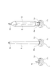
- FIG. 2 is a perspective view of a tray, an empty bobbin, and a fine spinning bobbin conveyed in the spinning system of FIG. 1.
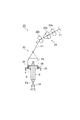
- FIG. 2 is a side view of a spinning unit of the spinning system of FIG. 1.
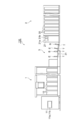
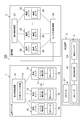
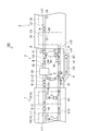
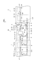
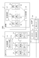
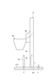
- FIG. 2 is a control block diagram of the spinning system of FIG. 1. It is a top view of the spinning system of FIG. It is a front view of the automatic winder of the spinning system of FIG. It is a top view of the spinning system in the 1st modification. It is a control block diagram of the spinning system in the 1st modification. It is a side view of the defective bobbin removal apparatus of the spinning system in the 2nd modification.
- the spinning system 100 includes an automatic winder 1, a ring spinning machine 2, and a transport device 3.
- the ring spinning machine 2 generates a yarn Y from the roving yarn and winds the yarn Y around an empty bobbin E (a bobbin around which the yarn Y is not wound) to form a spinning bobbin B.
- the automatic winder 1 winds the yarn Y of the fine spinning bobbin B to form a package P.
- the transport device 3 transports the spinning bobbin B from the ring spinning machine 2 to the automatic winder 1, and transports the empty bobbin E from the automatic winder 1 to the ring spinning machine 2.
- the spinning bobbin B and the empty bobbin E are each conveyed in a state of being set (placed) on the tray T.
- the tray T includes a disk-shaped base portion T1, a pin T2 protruding upward from the base portion T1, and an RF (Radio Frequency) tag (storage portion) provided on the base portion T1.
- the RF tag T3 may be built in the base portion T1 or attached to the outer surface of the base portion T1. Further, the RF tag T3 is not limited to a rectangular shape as shown in FIG. 2, and may be a donut shape (ring shape), for example.
- the spinning bobbin B and the empty bobbin E are set on the tray T with the pin T2 inserted into the bottom part Ea of the bobbin E, with the top part Eb of the bobbin E facing upward.
- the RF tag T3 stores information related to the spinning bobbin B set in the tray T.
- the state of the spinning bobbin B set in the tray T is managed by RFID (Radio Frequency Identification) technology.
- the configuration of the tray T is not limited to the above-described form.
- the base portion T1 may not be a disk shape, and the means for setting the spinning bobbin B and the empty bobbin E may not be the insertion of the pin T2.
- the installation place of the RF tag T3 may be a place where reading and writing can be performed by an RF writer (information writing unit) 31 and RF readers (information reading units) 18 and 41, which will be described later.
- the ring spinning machine 2 performs a spinning process that is a pre-process of the automatic winder 1.
- the ring spinning machine 2 includes a machine base control device 21 that controls the operation of the ring spinning machine 2 and a plurality of spinning units 20 that form the spinning bobbin B.
- the machine base control device 21 includes a display unit 21a such as a display and an operation unit 21b such as an input key.
- the display unit 21a displays the operation status of each spinning unit 20 and the like.
- the operation unit 21b is operated by an operator or the like in order to set operation conditions of each spinning unit 20 or the like.
- the display unit 21a and the operation unit 21b may be configured with a touch panel.
- the spinning unit 20 has a draft device 22 and a twisting device 23.
- the draft device 22 includes a back roller pair 22a, a middle roller pair 22b, and a front roller pair 22c.
- the back roller pair 22a, the middle roller pair 22b, and the front roller pair 22c are constituted by a bottom roller and a top roller, respectively.
- An apron belt is hung on each roller constituting the middle roller pair 22b.
- the back yarn pair 22a, the middle roller pair 22b, and the front roller pair 22c are rotated at a predetermined speed ratio, so that the coarse yarn Y1 unwound from the coarse yarn bobbin is drafted.
- the twisting device 23 includes a spindle shaft 24, a ring rail 25, a ring 26, and a traveler 27.
- the spindle shaft 24 holds the bottom portion Ea of the bobbin E with the top portion Eb of the bobbin E facing upward, and rotates the bobbin E.
- the ring rail 25 is movable in the axial direction of the bobbin E.
- the ring 26 is fixed to the ring rail 25.
- the traveler 27 is supported by the ring 26 and is movable along the ring 26.
- the roving yarn Y1 drafted in the drafting device 22 is inserted into the gap between the ring 26 and the traveler 27, and the end of the roving yarn Y1 is fixed to the bobbin E.
- the traveler 27 moves along the ring 26 so as to be pulled by the roving Y1.
- the ring rail 25 gradually moves from the bottom portion Ea side to the top portion Eb side while reciprocating within a predetermined range along the axial direction of the bobbin E.
- the rotation of the traveler 27 is delayed with respect to the rotation of the bobbin E, whereby the roving yarn Y1 is twisted to generate the yarn Y.
- the yarn Y is wound around the bobbin E, and the spinning bobbin B is It is formed.
- the ring spinning machine 2 having a plurality of spinning units 20 configured as described above is configured as a so-called simultaneous doffing type. That is, the ring spinning machine 2 stocks a plurality of empty bobbins E conveyed from the automatic winder 1 by the conveying device 3, and sets empty bobbins E in each spinning unit 20 at the same time. Start winding all at once. When winding of the yarn Y is completed in each spinning unit 20 and the spinning bobbin B is formed, the ring spinning machine 2 doffs all the spinning bobbins B all at once. Then, the ring spinning machine 2 removes the empty bobbins E stocked in the meantime from the tray T and sets them again in the spinning units 20 at the same time. Instead, the spinning bobbins B that have been doffed are placed in the tray T. Set all at once. The doffed spinning bobbin B is conveyed to the automatic winder 1 via the conveying device 3.
- the ring spinning machine 2 is provided with a spinning sensor (quality information acquisition unit) 28 and a sensor management control unit 29.
- the spinning sensor 28 is installed for each of the plurality of spinning units 20 included in the ring spinning machine 2.
- the spinning sensor 28 acquires quality information of the spinning bobbin B formed by the spinning unit 20.
- only one spinning sensor 28 may be provided for each of the plurality of spinning units 20, or one or a plurality of spinning sensors 28 may be provided for each spinning unit 20.
- the spinning sensor 28 includes, as quality information, information indicating the ambient environment (for example, ambient temperature and ambient humidity) of the ring spinning machine 2 and the state of each part of the spinning unit 20 (for example, installation failure, equipment or component consumption). ) And the operating state of the spinning unit 20 (for example, the speed at which the spinning bobbin B is formed in each spinning unit 20 (for example, the rotational speed of the traveler 27, the rotational speed of the spinning bobbin B)) To do.
- the ambient environment for example, ambient temperature and ambient humidity
- the state of each part of the spinning unit 20 for example, installation failure, equipment or component consumption.
- the operating state of the spinning unit 20 for example, the speed at which the spinning bobbin B is formed in each spinning unit 20 (for example, the rotational speed of the traveler 27, the rotational speed of the spinning bobbin B)
- the sensor management control unit 29 manages the quality information acquired by each spinning sensor 28.
- the sensor management control unit 29 outputs the quality information to be managed to the machine control device 11 of the automatic winder 1.
- the ring spinning machine 2 includes a transport path L2 for transporting the tray T and a transport conveyor C2.
- the conveyance path L2 includes a conveyance path L21 for conveying the tray T on which the spinning bobbins B formed by the respective spinning units 20 are set to the conveyance apparatus 3, and a tray on which an empty bobbin E is set from the conveyance apparatus 3.
- the transport conveyor C2 transports the tray T on which the spinning bobbin B or the empty bobbin E is set along the transport path L2.
- the automatic winder 1 includes a plurality of winding units 10 that form a package P from the spinning bobbin B, a doffing device 19 that doffs the package P, and each winding unit 10 and And a machine base control device 11 for controlling the doffing device 19.
- the automatic winder 1 includes a transport path L1 for transporting the tray T and a transport conveyor C1.
- the conveyance path L1 includes a conveyance path L11 for conveying the tray T on which the spinning bobbin B conveyed from the conveyance device 3 is set to each winding unit 10, and after the yarn Y is wound in the winding unit 10.
- the transport conveyor C1 transports the tray T on which the spinning bobbin B or the empty bobbin E is set along the transport path L1.
- the winding unit 10 includes a yarn feeding device 12, a tension applying device 13, a yarn joining device 14, a yarn clearer 15 (hereinafter simply referred to as a clearer), a winding device 16, In order from the upstream side to the downstream side of the yarn path. Furthermore, the winding unit 10 includes a unit control unit 17 and an RF reader (information reading unit) 18 as shown in FIG.
- the yarn supplying device 12 supports the spinning bobbin B conveyed through the conveying path L11 and assists the unwinding of the yarn Y of the spinning bobbin B. Further, the yarn supplying device 12 discharges the empty bobbin E after the yarn Y is all unwound to the transport path L12.
- the tension applying device 13 applies a predetermined tension to the yarn Y traveling from the yarn supplying device 12 toward the winding device 16.
- the yarn joining device 14 is a device that connects ends of the yarn Y that has been divided for some reason, such as when a yarn defect is detected and the yarn Y is cut.
- the clearer 15 monitors the state of the yarn Y traveling from the yarn supplying device 12 toward the winding device 16 between the yarn supplying device 12 and the winding device 16, and detects a yarn defect (for example, abnormal yarn thickness). , Foreign matter mixed into the yarn).
- the clearer 15 determines whether or not to detect the detected yarn defect based on the set clearing condition.
- the yarn Y is cut (cut) by the cutter to remove the yarn defect.
- the cutter is attached to the clearer 15. However, the cutter may be provided separately from the clearer 15.
- the winding device 16 unwinds the yarn Y from the fine spinning bobbin B supported by the yarn feeding device 12, and winds the unwound yarn Y to form a package P.
- the RF reader 18 reads a determination result as to whether or not the conveyed spinning bobbin B satisfies the quality standard value from the RF tag T3 of the tray T on which the spinning bobbin B conveyed to the winding unit 10 is set. . Details of the information stored in the RF tag T3 will be described later.
- the unit control unit 17 controls the operation of each unit of the winding unit 10 such as the yarn feeding device 12 based on an instruction from the machine base control device 11 or the like. Further, the unit control unit 17 controls the operation of the yarn feeding device 12 based on the determination result of whether or not the spinning bobbin B read by the RF reader 18 satisfies the quality reference value. Details of the operation of the yarn feeding device 12 when the spinning bobbin B does not satisfy the quality reference value will be described later.
- the doffing device 19 duffs the package P formed by each winding unit 10.
- One doffing device 19 is provided for the plurality of winding units 10.
- the doffing device 19 sends the duffed package P to a predetermined position (for example, a conveyor provided behind the machine base).
- the machine base control device 11 includes a display unit 11a, an operation unit (determination reference setting unit) 11b, and a defective bobbin determination unit (determination unit) 11c.
- the machine control device 11 includes, for example, a CPU [Central Processing Unit], a ROM [Read Only Memory], a RAM [Random Access Memory], an EEPROM [Electrically Erasable Programmable Read Only Memory], a communication device, a storage device, a display device, and the like. It is comprised by the electronic control unit which has an operating device etc.
- the display unit 11a and the operation unit 11b are configured by a touch panel in the present embodiment.
- the display part 11a and the operation part 11b are not limited to being comprised with a touch panel.
- the display unit 11a displays at least the winding conditions and operation data in the winding unit 10.
- the operation unit 11b is operated by an operator or the like in order to set the operating conditions of each winding unit 10 or the like.
- the defective bobbin determination unit 11c acquires the quality information of the spinning bobbin B acquired by each spinning sensor 28 from the sensor management control unit 29 via communication.
- the defective bobbin determination unit 11c determines whether the quality of the spinning bobbin B satisfies a predetermined quality standard value for each spinning bobbin B based on the acquired quality information.
- the spinning bobbin B that does not satisfy the quality standard value is referred to as a defective bobbin B1 (see FIG. 5).
- the defective bobbin determination unit 11c outputs a determination result (whether or not it is a defective bobbin B1) to the RF writer 31 of the transport device 3.
- the determination result includes identification information for specifying the spinning unit 20 that formed the spinning bobbin B.
- the spinning unit 20 in which the spinning bobbin B is formed can be specified based on the installation position of the spinning sensor 28 that acquired the quality information of the spinning bobbin B.
- the defective bobbin B1 tends to include many yarn defects to be removed as compared with the fine spinning bobbin B that satisfies the quality standard value. For this reason, when the defective bobbin B1 is wound in the winding unit 10, the operation efficiency of winding tends to be low because the yarn defect removal operation occurs frequently.
- the quality standard value may be changed by the operator.
- the operation unit 11b of the machine base control device 11 may accept an input operation for setting a quality reference value by an operator. Then, the defective bobbin determination unit 11c may determine whether or not the quality of the spinning bobbin B satisfies the quality reference value based on the quality reference value changed by the operator's input operation.
- the operation unit that receives an input operation for setting the quality reference value by the operator is not limited to the operation unit 11b provided in the machine base control device 11, and may be an operation unit other than the operation unit 11b.
- the transport device 3 transports the spinning bobbin B from the ring spinning machine 2 to the automatic winder 1 and transports the empty bobbin E from the automatic winder 1 to the ring spinning machine 2 as described above. To do.
- the transport device 3 includes a transport path L3 for transporting the tray T and a transport conveyor C3.
- the conveyance path L3 includes a conveyance path L31 for conveying the tray T on which the spinning bobbin B conveyed from the ring spinning machine 2 is set to the automatic winder 1, and after the yarn Y is wound up in the automatic winder 1.
- the transport path L32 connects the transport path L22 of the ring spinning machine 2 and the transport path L12 of the automatic winder 1.
- the transport path L3 includes bypass paths L33 and L34 that connect the transport path L31 and the transport path L32.
- the bypass path L33 is provided closer to the automatic winder 1 than the bypass path L34.
- the automatic winder 1 and the ring spinning machine 2 are connected to each other by the conveyance path L2 provided in the ring spinning machine 2, the conveyance path L3 provided in the conveyance device 3, and the conveyance path L1 provided in the automatic winder 1.
- a conveyance path for conveying the fine spinning bobbin B and the empty bobbin E is formed between them.
- the conveying device 3 includes an RF writer (information writing unit) 31, a remaining yarn amount confirmation sensor 32, a yarn end preparation device 33, a yarn presence / absence confirmation sensor 34, a remaining yarn removal device 35, and defective bobbin discharge. And a device (winding prevention mechanism, discharge device) 4.
- the RF writer 31 is provided in the vicinity of the conveyance path L31 for conveying the spinning bobbin B formed by the ring spinning machine 2 to the automatic winder 1.
- the RF writer 31 determines the defective bobbin in the spinning bobbin B to the RF tag T3 of the tray T on which the spinning bobbin B is set.
- the determination result of the part 11c (whether it is a defective bobbin B1 and the identification information of the spinning unit 20 that formed the spinning bobbin B) is written.
- the RF writer 31 is not limited to being provided in the transport device 3.
- An RF writer 31 may be provided at the exit in the conveying direction of the spinning bobbin B of the ring spinning machine 2. Further, an RF writer 31 may be provided for each spinning unit 20.
- the transport device 3 further includes a transfer unit, and in the transfer unit, the tray for the ring spinning machine 2 is changed into a tray for the automatic winder 1. The spinning bobbin B may be transferred.
- the RF writer 31 is provided at a position slightly away from the transfer unit or the transfer unit on the downstream side in the transport direction of the spinning bobbin B, and is attached to the RF tag attached to the tray for the automatic winder 1. Information about bobbin B may be written.
- the remaining yarn amount confirmation sensor 32 detects the remaining yarn amount of bobbins (spun bobbin B and empty bobbin E) conveyed along the conveyance path L31.
- the yarn end preparation device 33 allows the automatic winder 1 to capture the yarn end so that the yarn end can be captured.
- the yarn end is processed for B.
- the yarn end preparation device 33 does not perform the yarn end processing.
- the conveyance conveyor C3 conveys the fine spinning bobbin B that has been subjected to the yarn end processing in the yarn end preparation device 33 to the automatic winder 1 along the conveyance path L31.
- the transport conveyor C3 passes the empty bobbin E through the bypass path L33. Through the transport path L31 to the transport path L32.
- the yarn presence / absence confirmation sensor 34 detects whether or not the yarn Y remains on the bobbin (spun bobbin B or empty bobbin E) conveyed along the conveyance path L32.
- the transport conveyor C3 passes the spinning bobbin B with the thread Y remaining from the transport path L32 via the bypass path L34. Then, it is conveyed to the remaining yarn removing device 35.
- the residual yarn removing device 35 removes the yarn Y from the fine spinning bobbin B on which the yarn Y conveyed along the bypass path L34 remains, and turns it into an empty bobbin E.
- the empty bobbin E from which the yarn Y has been removed by the residual yarn removing device 35 is transported from the bypass route L34 to the transport route L31 by the transport conveyor C3.
- the defective bobbin discharging device 4 discharges the defective bobbin B1 returned to the conveying device 3 without being wound by the winding unit 10 to the outside of the conveying path L3.
- yarn Y of defective bobbin B1 in the winding unit 10 is mentioned later in detail.
- the defective bobbin discharging device 4 includes an RF reader 41, a discharging control unit 42, a defective bobbin discharging path L4, and a discharging conveyor C4.
- the defective bobbin discharge path L4 is branched from the middle part of the transport path L32 for transporting the tray T from the automatic winder 1 to the ring spinning machine 2.
- the discharge conveyor C4 takes in the tray T in which the defective bobbin B1 is set from the conveyance path L32 to the defective bobbin discharge path L4 based on the control of the discharge control unit 42.
- the RF reader 41 is provided in the vicinity of the conveyance path L32 and at a position closer to the automatic winder 1 than the connecting portion between the conveyance path L32 and the defective bobbin discharge path L4.
- the RF reader 41 determines from the RF tag T3 of the tray T transported along the transport path L32 whether the defective bobbin determining unit 11c determines whether the spinning bobbin B set on the tray T is the defective bobbin B1. ) Without contact.
- the RF reader 41 outputs the read determination result to the discharge control unit 42.
- the discharge controller 42 controls the discharge conveyor C4 so that the defective bobbin B1 is discharged from the conveyance path L32 to the defective bobbin discharge path L4. .
- the winding unit 10 does not wind the yarn Y from the defective bobbin B1 when the spinning bobbin B conveyed from the conveying device 3 is the defective bobbin B1.
- the RF reader 18 determines from the RF tag T3 of the tray T in which the spinning bobbin B is set, the determination result in the defective bobbin determination unit 11c (the spinning bobbin B set in the tray T is the defective bobbin B1). Read out). The RF reader 18 outputs the read determination result to the unit controller 17.
- the unit controller 17 When the determination result read by the RF reader 18 is the defective bobbin B1, the unit controller 17 does not unwind the yarn Y from the defective bobbin B1, that is, the yarn Y is supplied to the winding device 16. The yarn feeding device 12 is controlled so that the defective bobbin B1 is discharged to the transport path L12 without being supplied. If the determination result read by the RF reader 18 is not a defective bobbin B1, the unit controller 17 controls the operation of each part of the winding unit 10 to set the spinning bobbin set in the yarn feeder 12 The yarn Y of B is supplied to the winding device 16.
- the yarn feeding device 12 constitutes a winding prevention mechanism that prevents the yarn Y of the defective bobbin B1 from being wound up by the winding device 16.
- the yarn supplying device 12 can prevent the yarn Y of the defective bobbin B1 from being wound by the winding device 16 based on the determination result of the defective bobbin determining unit 11c read by the RF reader 18.
- the RF reader 18 reads identification information for specifying the spinning unit 20 that formed the spinning bobbin B from the RF tag T3 of the tray T. .
- the RF reader 18 outputs identification information for specifying the read spinning unit 20 to the machine control device 11.
- the machine control device 11 can identify the spinning unit 20 that forms the spinning bobbin B for the spinning bobbin B set in the yarn feeding device 12.
- the machine control device 11 may not specify the spinning unit 20 that forms the spinning bobbin B.
- the yarn feeding device 12 of the winding unit 10 conveys the defective bobbin B1 without unwinding the yarn Y from the defective bobbin B1.
- the sheet is discharged to L12 and returned to the transfer device 3. That is, the yarn feeding device 12 of the winding unit 10 prevents the yarn Y of the defective bobbin B1 from being wound.
- the automatic winder 1 can wind the yarn Y of the fine spinning bobbin B that satisfies the quality standard value without winding the yarn Y of the defective bobbin B1. For this reason, the spinning system 100 can wind the yarn Y of the fine spinning bobbin B without reducing the operating efficiency of the automatic winder 1.
- the defective bobbin discharging device 4 discharges the defective bobbin B1 from the conveyance path L32 to the defective bobbin discharging path L4. This prevents the defective bobbin B1 from being conveyed to the automatic winder 1 again. In this manner, the defective bobbin discharging device 4 can also prevent the yarn Y of the defective bobbin B1 from being wound up by the winding unit 10.
- the RF writer 31 writes the determination result determined by the defective bobbin determination unit 11c in the RF tag T3 of the tray T.
- the RF reader 18 reads the determination result from the RF tag T3.
- the winding unit 10 is based on the determination result read by the RF reader 18, and among the plurality of spinning bobbins B transported in the state of being set on the tray T, the defect does not satisfy the quality standard value.
- Bobbin B1 can be specified.
- the operation unit 11b of the winding unit 10 receives an input operation for setting a quality reference value by an operator. Then, the defective bobbin determination unit 11c may determine whether the quality of the spinning bobbin B satisfies the quality standard value based on the accepted quality standard value. In this case, the operator of the spinning system 100 can set the quality of the spinning bobbin B that prevents the winding of the yarn Y in the winding unit 10 by operating the operation unit 11b.
- the spinning sensor 28 acquires at least one of the ambient environment of the ring spinning machine 2, information indicating the state of each part of the spinning unit 20, and the operating state of the spinning unit 20 as quality information.
- the defective bobbin determination unit 11c can determine whether or not the quality of the spinning bobbin B satisfies the quality standard value based on information such as the surrounding environment of the ring spinning machine 2 included in the quality information.
- the winding prevention method implemented in the spinning system 100 includes an acquisition step of acquiring quality information regarding the quality of the spinning bobbin B by the spinning sensor 28 installed in the ring spinning machine 2, and the quality acquired in the acquisition step.
- a determination step for determining whether or not the quality of the spinning bobbin B satisfies a predetermined quality reference value for each spinning bobbin B based on the information, and the quality reference value in the determination step A winding prevention step of preventing the yarn Y of the fine spinning bobbin B determined not to satisfy the condition from being wound by the winding unit 10 by the yarn feeding device 12. According to this winding prevention method, as described above, the yarn Y of the spinning bobbin B can be wound without reducing the operating efficiency of the ring spinning machine 2.
- the spinning system 100A according to the first modification includes a transport device 3A instead of the transport device 3 of the spinning system 100 according to the embodiment.
- the transfer device 3A includes a defective bobbin discharge device (winding prevention mechanism, discharge device) 5 instead of the defective bobbin discharge device 4 of the transfer device 3 in the embodiment.
- the defective bobbin discharging device 5 discharges the defective bobbin B1 from the conveyance path L31 along which the fine spinning bobbin B is conveyed.
- the defective bobbin discharge device 5 includes a discharge control unit 51, a defective bobbin discharge path L5, and a discharge conveyor C5.
- the defective bobbin discharge path L5 is provided to be branched from a middle portion of the transport path L31 for transporting the tray T (spun bobbin B) from the ring spinning machine 2 to the automatic winder 1.
- the defective bobbin discharge path L5 is connected to a position closer to the ring spinning machine 2 than the connection part between the bypass path L34 and the transfer path L31 in the transfer path L31.
- the discharge conveyor C5 takes in the tray T in which the defective bobbin B1 is set from the conveyance path L31 to the defective bobbin discharge path L5 based on the control of the discharge control unit 51.
- the discharge control unit 51 acquires the determination result from the defective bobbin determination unit 11c, and identifies the spinning unit 20 that formed the defective bobbin B1 from the acquired determination result.
- the discharge control unit 51 determines that the defective bobbin B1 is defective when the spinning bobbin B (defective bobbin B1) formed by the specified spinning unit 20 passes through the connecting portion between the defective bobbin discharge path L5 and the conveyance path L31.
- the discharge conveyor C5 is controlled so as to be discharged to the bobbin discharge path L5.
- the ring spinning machine 2 doffs all the spinning bobbins B all at once, and sets the fine spinning bobbins B on the tray T all at once and conveys them to the conveying device 3. Accordingly, the plurality of spinning bobbins B respectively formed by the plurality of spinning units 20 are sequentially transported to the transport device 3 along the order of the spinning units 20, for example. For this reason, since the discharge control unit 51 has already identified the identification information of the spinning unit 20 that formed the defective bobbin B1 from the obtained determination result, for example, the spinning bobbin B that is sequentially transported along the transport path L31. The defective bobbin B1 can be specified based on the order.
- the defective bobbin discharging apparatus 5 can discharge the defective bobbin B1 without reading the determination result from the RF tag T3.
- the RF writer 31 may not write the determination result as to whether or not the spinning bobbin B satisfies the quality reference value in the RF tag T3 of the tray T.
- the RF writer 31 may write only the identification information of the spinning unit 20 that formed the spinning bobbin B on the RF tag T3 of the tray T.
- the RF writer 31 acquires the determination result and identification information from the defective bobbin determination unit 11c via the discharge control unit 51. can do.
- the RF writer 31 may acquire the determination result and the identification information directly from the defective bobbin determination unit 11c. Note that when the defective bobbin discharging apparatus 5 discharges the defective bobbin B1 without reading the determination result from the RF tag T3, the RF writer 31 and the RF reader 18 may not be provided.
- the defective bobbin discharging device 5 can discharge the defective bobbin B1 from the conveying path L31 for conveying the fine spinning bobbin B to the defective bobbin discharging path L5 outside the conveying path L31.
- the spinning system 100A can prevent the yarn Y of the defective bobbin B1 from being wound by the winding unit 10, and winds the yarn Y of the fine spinning bobbin B without reducing the operating efficiency of the automatic winder 1. Can do.
- the defective bobbin discharging path L5 of the defective bobbin discharging apparatus 5 is connected to a conveying path L31 for conveying the spinning bobbin B from the ring spinning machine 2 to the automatic winder 1.
- the defective bobbin discharging device 5 can discharge the defective bobbin B1 to the defective bobbin discharging path L5 before the defective bobbin B1 is conveyed from the ring spinning machine 2 to the automatic winder 1.
- the defective bobbin discharging device 5 in the first modified example reads the determination result stored in the RF tag T3 of the tray T by the RF reader and transports the defective bobbin B1 in the same manner as the defective bobbin discharging device 4 in the embodiment. It may be discharged from the path L31 to the defective bobbin discharge path L5. That is, the defective bobbin discharging device 4 in the embodiment may be provided for the transport path L31.
- the position where the defective bobbin discharging device 5 is provided is not limited to the transport path L31.
- the defective bobbin discharging device 5 may be provided at any position on the transport paths L1 to L3 as long as the defective bobbin B1 passes through. That is, the defective bobbin discharging device 5 is not limited to being provided in the transport device 3, and may be provided in the automatic winder 1 or the ring spinning machine 2.
- the spinning system in the second modified example includes a defective bobbin removing device (winding prevention mechanism, discharging device) 6 shown in FIG. 9 instead of the defective bobbin discharging device 5 in the first modified example.
- the defective bobbin removing device 6 is provided on a conveyance path L31 for conveying the spinning bobbin B from the ring spinning machine 2 to the automatic winder 1.
- the defective bobbin removing device 6 includes a bobbin removing unit 61, a bobbin inserting unit 62, a defective bobbin housing unit 63, and an RF reader (information reading unit) 64.
- the RF reader 64 is configured such that the transported spinning bobbin B is defective from the RF tag T3 of the tray T on which the spinning bobbin B transported to the defective bobbin removing device 6 is set. The determination result of whether or not it is B1 is read.
- the bobbin removing unit 61 is a member extending in the vertical direction.
- the bobbin removing unit 61 extracts the conveyed defective bobbin B1 from the tray T.
- the bobbin removing unit 61 includes a plurality of rollers (not shown) and the like, and the defective bobbin B1 can be extracted from the tray T by rotating the rollers. Note that when the transported spinning bobbin B is not the defective bobbin B1, the bobbin removing unit 61 does not extract the spinning bobbin B from the tray T.
- the defective bobbin B1 is discharged out of the conveyance path L31 (removed from the conveyance path L31).
- the upper part of the bobbin inserting part 62 is attached to the upper part of the bobbin removing part 61.
- the lower end portion of the bobbin inserting portion 62 extends to the vicinity of the upper portion of the defective bobbin accommodating portion 63.
- the bobbin removing unit 61 lifts the defective bobbin B1 extracted from the tray T upward and sends it to the bobbin inserting unit 62.
- the bobbin loading part 62 is formed in a slide shape, and slides the defective bobbin B1 sent from the bobbin removing part 61 into the defective bobbin accommodating part 63.
- the defective bobbin accommodating portion 63 is formed in a box shape having an upper portion opened.
- the defective bobbin accommodating portion 63 accommodates the defective bobbin B1 thrown from the bobbin throwing portion 62.
- the defective bobbin removing device 6 removes the defective bobbin B1 from the transport path L31 by pulling out the defective bobbin B1 from the tray T.
- the spinning system in the second modification can prevent the yarn Y of the defective bobbin B1 from being wound by the winding unit 10, and the yarn Y of the fine spinning bobbin B without reducing the operating efficiency of the automatic winder 1. Can be wound up.
- the bobbin removing unit 61 of the defective bobbin removing device 6 acquires the determination result from the defective bobbin determining unit 11c in the same manner as the defective bobbin discharging device 5 of the second modification, and determines the defective bobbin B1 from the acquired determination result.
- the formed spinning unit 20 may be specified.
- the bobbin removing unit 61 may pull out the defective bobbin B1 from the tray T when the spinning bobbin B (defective bobbin B1) formed by the specified spinning unit 20 passes through the bobbin removing unit 61.
- the defective bobbin removing device 6 can remove the defective bobbin B1 without reading the determination result from the RF tag T3.
- the defective bobbin removing device 6 in the second modified example is not limited to the configuration in which the defective bobbin B1 is pulled upward from the tray T.
- the defective bobbin removing device 6 may have another configuration as long as the defective bobbin B1 can be removed from the tray T.
- the position where the defective bobbin removing device 6 is provided is not limited to the transport path L31.
- the defective bobbin removing device 6 may be provided in the remaining yarn removing device 35.
- the defective bobbin removing device 6 may be provided at any position on the transport paths L1 to L3 as long as the defective bobbin B1 passes through. That is, the defective bobbin removing device 6 is not limited to being provided in the transport device 3, and may be provided in the automatic winder 1 or the ring spinning machine 2.
- the defective bobbin determination unit 11 c that determines the quality of the spinning bobbin B based on the quality information acquired by the spinning sensor 28 is not limited to being provided in the machine control device 11 of the automatic winder 1.
- the defective bobbin determination unit 11c may be provided in the spinning sensor 28 itself, may be provided in the machine control device 21 of the ring spinning machine 2, or may be a sensor that manages the spinning sensor 28. It may be provided in the management control unit 29 or may be provided in the unit control unit 17 of the winding unit 10.
- the quality information of the spinning bobbin B for determining whether or not it is a defective bobbin B1 is obtained from the sensor management control unit 29.
- This quality information is obtained from the RF of the tray T. It may be written in the tag T3. And based on the quality information written in RF tag T3, the unit control part 17 of the winding unit 10 may determine whether it is a defective bobbin B1.
- the RF writer 31 provided in the transfer device 3 acquires the quality information of each spinning bobbin B acquired by the spinning sensor 28 via communication from the sensor management control unit 29 and acquires the quality information.
- the quality information is written in the RF tag T3 of the tray T in which the fine spinning bobbin B is set.
- the RF writer 31 may or may not write identification information for specifying the spinning unit 20 in which the spinning bobbin B is formed.
- Each winding unit 10 includes an RF writer in addition to the RF reader 18.
- the RF reader 18 reads the quality information of the spinning bobbin B from the RF tag T3 of the tray T on which the spinning bobbin B is set.
- Each unit controller 17 determines whether or not the bobbin B1 is defective based on the quality information of the spinning bobbin B read by the RF reader 18.
- the RF writer provided in the winding unit 10 writes the discharge flag of the defective bobbin B1 to the RF tag T3 when the determination result of the unit control unit 17 is the defective bobbin B1. Then, the RF reader 41 of the defective bobbin discharging apparatus 4 reads the discharge flag from the RF tag T3. When the discharge flag is read by the RF reader 41, the defective bobbin discharging device 4 discharges the tray T in which the discharge flag is written (the tray T in which the defective bobbin B1 is set) to the defective bobbin discharging path L4.
- the RF readers 18, 41 and 64 are not limited to reading information from the RF tag T3 in a non-contact manner, and may read information by a contact type.
- the conveyance devices 3 and 3A are provided with a remaining yarn amount confirmation sensor 32, a yarn end preparation device 33, a yarn presence / absence confirmation sensor 34, a remaining yarn removal device 35, and bypass paths L33 and L34.
- these can be omitted as appropriate.
- the yarn of the spinning bobbin can be wound without reducing the operating efficiency of the automatic winder.
- SYMBOLS 1 Automatic winder, 2 ... Ring spinning machine, 4, 5 ... Defective bobbin discharge device (winding prevention mechanism, discharge device), 6 ... Defective bobbin removal device (winding prevention mechanism, discharge device), 10 ... Winding unit , 11b ... operation unit (determination reference setting unit), 11c ... defective bobbin determination unit (determination unit), 12 ... yarn feeding device (winding prevention mechanism), 16 ... winding device, 18, 41, 64 ... RF reader ( (Information reading unit), 20 ... spinning unit, 28 ... spinning sensor (quality information acquisition unit), 31 ... RF writer (information writing unit), 100 ... spinning system, B ... spinning bobbin, B1 ...
Landscapes
- Engineering & Computer Science (AREA)
- Quality & Reliability (AREA)
- Mechanical Engineering (AREA)
- Textile Engineering (AREA)
- Replacing, Conveying, And Pick-Finding For Filamentary Materials (AREA)
- Filamentary Materials, Packages, And Safety Devices Therefor (AREA)
- Spinning Or Twisting Of Yarns (AREA)
Abstract
紡績システム100は、自動ワインダ1と、リング精紡機2とを備える。紡績システム100は、リング精紡機2に設置され、精紡ボビンBの品質に関する品質情報を取得する精紡センサ28と、精紡センサ28で取得された品質情報に基づいて、それぞれの精紡ボビンBについて精紡ボビンBの品質が予め定められた品質基準値を満たすか否かを判定する不良ボビン判定部11cと、品質基準値を満たさないと判定された不良ボビンB1の糸Yが巻取ユニット10で巻き取られることを阻止する給糸装置12と、を備える。
Description
本発明は、紡績システム、及び巻取阻止方法に関する。
糸が巻き取られた精紡ボビンを形成する複数の精紡ユニットを有するリング精紡機と、精紡ボビンの糸を巻き取ってパッケージを形成する複数の巻取ユニットを有する自動ワインダと、リング精紡機から自動ワインダへ精紡ボビンを搬送する搬送装置と、を備える紡績システムがある。このような紡績システムが、例えば、特許文献1に記載されている。
このような自動ワインダの巻取ユニットは、巻き取り中の糸の品質をクリアラによって測定し、糸欠陥の有無を検出する。糸欠陥が検出された場合、巻取ユニットは、糸の巻き取りを停止して糸欠陥を除去し、糸継ぎを行った後に巻き取りを再開する。また、巻取ユニットは、糸欠陥が頻発して検出される場合、巻き取り中の精紡ボビンを不良ボビンと判定し、不良ボビンを外部に排出する。
巻取ユニットに供給された精紡ボビンが不良ボビンである場合、供給された精紡ボビンを不良ボビンと判定して外部に排出するまでの間に、巻き取りの停止、糸欠陥の除去、及び糸継ぎ動作が繰り返されるため、自動ワインダの稼働効率が低下する。
そこで、本発明は、自動ワインダの稼働効率を低下させることなく精紡ボビンの糸を巻き取ることが可能な紡績システム、及び巻取阻止方法を提供することを目的とする。
本発明は、糸が巻き取られた精紡ボビンを形成する精紡ユニットを複数有するリング精紡機と、リング精紡機で形成された精紡ボビンの糸を巻き取ってパッケージを形成する巻取ユニットを複数有する自動ワインダと、を備える紡績システムであって、リング精紡機に設置され、精紡ボビンの品質に関する品質情報を取得する品質情報取得部と、品質情報取得部で取得された品質情報に基づいて、それぞれの精紡ボビンについて精紡ボビンの品質が予め定められた品質基準値を満たすか否かを判定する判定部と、判定部において品質基準値を満たさないと判定された精紡ボビンの糸が巻取ユニットで巻き取られることを阻止する巻取阻止機構と、を備える。
この紡績システムでは、品質基準値を満たさない精紡ボビンの糸の巻き取りが阻止される。これにより、自動ワインダは、品質基準値を満たさない精紡ボビンの糸を巻き取ること無く、品質基準値を満たす精紡ボビンの糸を巻き取ることができる。このため、紡績システムは、自動ワインダの稼働効率を低下させることなく精紡ボビンの糸を巻き取ることができる。
紡績システムは、自動ワインダとリング精紡機との間で精紡ボビン及び空のボビンを搬送する搬送経路を備え、巻取阻止機構は、品質基準値を満たさないと判定された精紡ボビンを搬送経路外に排出する排出装置を備えていてもよい。この場合、排出装置は、品質基準値を満たさない精紡ボビンを搬送経路外に排出することによって、品質基準値を満たさない精紡ボビンの糸が巻取ユニットで巻き取られることを阻止できる。
紡績システムにおいて、排出装置は、搬送経路から分岐して設けられた不良ボビン排出経路を備え、品質基準値を満たさないと判定された精紡ボビンを搬送経路から不良ボビン排出経路に排出する不良ボビン排出装置によって構成されてもよい。この場合、不良ボビン排出装置は、品質基準値を満たさない精紡ボビンを搬送経路から不良ボビン排出経路に排出することによって、品質基準値を満たさない精紡ボビンの糸が巻取ユニットで巻き取られることを阻止できる。
紡績システムにおいて、不良ボビン排出経路は、搬送経路のうち、リング精紡機から自動ワインダへ精紡ボビンが搬送される搬送経路の途中の部分から分岐して設けられていてもよい。この場合、不良ボビン排出装置は、品質基準値を満たさない精紡ボビンがリング精紡機から自動ワインダに搬送される前に、品質基準値を満たさない精紡ボビンを不良ボビン排出経路に排出できる。
紡績システムにおいて、排出装置は、搬送経路上に設けられ、品質基準値を満たさないと判定された精紡ボビンを搬送経路から除去する不良ボビン除去装置によって構成されてもよい。この場合、不良ボビン除去装置は、品質基準値を満たさない精紡ボビンを搬送経路から除去することによって、品質基準値を満たさない精紡ボビンの糸が巻取ユニットで巻き取られることを阻止できる。
紡績システムは、自動ワインダとリング精紡機との間で精紡ボビン及び空のボビンを搬送する搬送経路を備え、自動ワインダは、搬送経路を介して搬送された精紡ボビンを支持するとともに精紡ボビンの糸の解舒を補助し、糸が全て解舒された後の空のボビンを搬送経路に排出する給糸装置と、精紡ボビンから糸を解舒し、解舒した糸を巻き取る巻取装置と、を備え、巻取阻止機構は、給糸装置によって構成され、給糸装置は、搬送された精紡ボビンが品質基準値を満たさないと判定された精紡ボビンである場合、精紡ボビンから糸が解舒されることなく精紡ボビンを搬送経路に排出してもよい。これにより、給糸装置は、品質基準値を満たさない精紡ボビンが搬送された場合、精紡ボビンから糸が解舒されることなく精紡ボビンを搬送経路に排出することによって、品質基準値を満たさない精紡ボビンの糸が巻取ユニットで巻き取られることを阻止できる。
紡績システムは、判定部における精紡ボビンの品質の判定結果を書き込む情報書込部と、情報書込部で書き込まれた判定結果を読み出す情報読出部と、を備え、精紡ボビンは、トレーにセットされた状態で搬送経路に沿って搬送され、情報書込部は、トレーに設けられた記憶部に判定結果を書き込み、情報読出部は、トレーの記憶部から判定結果を読み出し、巻取阻止機構は、情報読出部で読み出された判定結果に基づいて、精紡ボビンの糸が巻取ユニットで巻き取られることを阻止してもよい。この場合、巻取阻止機構は、情報読出部で読み出された判定結果に基づいて、トレーにセットされた状態で搬送される複数の精紡ボビンのうち、品質基準値を満たさない精紡ボビンを特定できる。
紡績システムは、オペレータによる品質基準値の設定の入力操作を受け付ける判定基準設定部を備え、判定部は、判定基準設定部で受け付けられた品質基準値に基づいて精紡ボビンの品質が品質基準値を満たすか否かを判定してもよい。この場合、紡績システムのオペレータは、判定基準設定部を操作することで、巻取ユニットにおいて糸の巻き取りを阻止する精紡ボビンの品質を設定できる。
紡績システムにおいて、品質情報は、リング精紡機の周囲の温度、リング精紡機の周囲の湿度、精紡ユニットの各部の状態を示す情報、精紡ユニットの運転状態の少なくとも1つを含んでいてもよい。この場合、判定部は、品質情報に含まれるリング精紡機の周囲の温度等の情報に基づいて、精紡ボビンの品質が品質基準値を満たすか否かを判定できる。
本発明は、糸が巻き取られた精紡ボビンを形成する精紡ユニットを複数有するリング精紡機と、リング精紡機で形成された精紡ボビンの糸を巻き取ってパッケージを形成する巻取ユニットを複数有する自動ワインダと、を備える紡績システムで実施される巻取阻止方法であって、リング精紡機に設置された品質情報取得部によって、精紡ボビンの品質に関する品質情報を取得する取得ステップと、取得ステップにおいて取得された品質情報に基づいて、それぞれの精紡ボビンについて精紡ボビンの品質が予め定められた品質基準値を満たすか否かを判定部によって判定する判定ステップと、判定ステップにおいて品質基準値を満たさないと判定された精紡ボビンの糸が巻取ユニットで巻き取られることを巻取阻止機構によって阻止する巻取阻止ステップと、を含む。
この巻取阻止方法では、巻取阻止ステップにおいて、品質基準値を満たさない精紡ボビンの糸の巻き取りが阻止される。これにより、自動ワインダは、品質基準値を満たさない精紡ボビンの糸を巻き取ること無く、品質基準値を満たす精紡ボビンの糸を巻き取ることができる。これにより、この巻取阻止方法では、自動ワインダの稼働効率を低下させることなく精紡ボビンの糸を巻き取ることができる。
本発明によれば、自動ワインダの稼働効率を低下させることなく精紡ボビンの糸を巻き取ることができる。
以下、本発明の実施形態について、図面を参照して説明する。なお、各図において同一又は相当部分には同一符号を付し、重複する説明を省略する。
図1に示されるように、紡績システム100は、自動ワインダ1と、リング精紡機2と、搬送装置3と、を備えている。リング精紡機2は、粗糸から糸Yを生成し、その糸Yを空のボビンE(糸Yの巻かれていないボビン)に巻き取って精紡ボビンBを形成する。自動ワインダ1は、精紡ボビンBの糸Yを巻き取ってパッケージPを形成する。搬送装置3は、リング精紡機2から自動ワインダ1に精紡ボビンBを搬送し、自動ワインダ1からリング精紡機2に空のボビンEを搬送する。
精紡ボビンB及び空のボビンEは、それぞれ、トレーTにセット(載置)された状態で搬送される。図2に示されるように、トレーTは、円板状のベース部T1と、ベース部T1から上側に突出するピンT2と、ベース部T1に設けられたRF(Radio Frequency)タグ(記憶部)T3と、を有している。なお、RFタグT3は、ベース部T1に内蔵されていてもよく、ベース部T1の外面に取り付けられていてもよい。また、RFタグT3は、図2に示されるように矩形状であることに限定されず、例えば、ドーナツ状(リング状)であってもよい。精紡ボビンB及び空のボビンEは、それぞれ、ボビンEのボトム部EaにピンT2が差し込まれることで、ボビンEのトップ部Ebが上側に向いた状態でトレーTにセットされる。RFタグT3は、トレーTにセットされた精紡ボビンBに関する情報を記憶する。紡績システム100では、トレーTにセットされた精紡ボビンBの状況がRFID(Radio Frequency Identification:電波による個体識別)技術によって管理される。なお、トレーTの構成は上述の形態に限定されない。例えば、ベース部T1は円板状でなくてもよいし、また、精紡ボビンB及び空のボビンEをセットする手段はピンT2の差し込みでなくてもよい。RFタグT3の設置場所も、後述のRFライタ(情報書込部)31及びRFリーダ(情報読出部)18及び41で読み書き可能な場所であればよい。
[リング精紡機の構成]
リング精紡機2は、自動ワインダ1の前工程の精紡工程を実施する。リング精紡機2は、図1に示されるように、リング精紡機2の動作を制御する機台制御装置21と、精紡ボビンBを形成する複数の精紡ユニット20と、を備えている。機台制御装置21は、ディスプレイ等の表示部21aと、入力キー等の操作部21bと、を有している。表示部21aは、各精紡ユニット20の運転状況等を表示する。操作部21bは、オペレータ等によって各精紡ユニット20の運転条件の設定等を行うために操作される。なお、表示部21aと操作部21bとは、タッチパネルで構成されていてもよい。
リング精紡機2は、自動ワインダ1の前工程の精紡工程を実施する。リング精紡機2は、図1に示されるように、リング精紡機2の動作を制御する機台制御装置21と、精紡ボビンBを形成する複数の精紡ユニット20と、を備えている。機台制御装置21は、ディスプレイ等の表示部21aと、入力キー等の操作部21bと、を有している。表示部21aは、各精紡ユニット20の運転状況等を表示する。操作部21bは、オペレータ等によって各精紡ユニット20の運転条件の設定等を行うために操作される。なお、表示部21aと操作部21bとは、タッチパネルで構成されていてもよい。
図3に示されるように、精紡ユニット20は、ドラフト装置22と、加撚装置23と、を有している。
ドラフト装置22は、バックローラ対22aと、ミドルローラ対22bと、フロントローラ対22cと、を有している。バックローラ対22a、ミドルローラ対22b及びフロントローラ対22cは、それぞれ、ボトムローラ及びトップローラによって構成されている。ミドルローラ対22bを構成する各ローラには、エプロンベルトが架けられている。ドラフト装置22では、バックローラ対22a、ミドルローラ対22b及びフロントローラ対22cが所定の速度比で回転させられることで、粗糸ボビンから解舒された粗糸Y1がドラフトされる。
加撚装置23は、スピンドル軸24と、リングレール25と、リング26と、トラベラ27と、を有している。スピンドル軸24は、ボビンEのトップ部Ebが上側に向いた状態でボビンEのボトム部Eaを保持し、ボビンEを回転させる。リングレール25は、ボビンEの軸線方向に移動可能である。リング26は、リングレール25に固定されている。トラベラ27は、リング26に支持されており、リング26に沿って移動可能である。
加撚装置23では、ドラフト装置22においてドラフトされた粗糸Y1がリング26とトラベラ27との隙間に挿通され、その粗糸Y1の端部がボビンEに固定される。その状態で、スピンドル軸24がボビンEを回転させると、トラベラ27が粗糸Y1に引っ張られるようにしてリング26に沿って移動する。このとき、リングレール25が、ボビンEの軸線方向に沿った所定の範囲で往復動しつつ、ボトム部Ea側からトップ部Eb側に徐々に移動する。加撚装置23では、トラベラ27の回転がボビンEの回転に遅れることで粗糸Y1に撚りが加えられて糸Yが生成され、その糸YがボビンEに巻き取られて精紡ボビンBが形成される。
以上のように構成された精紡ユニット20を複数有するリング精紡機2は、いわゆる一斉ドッフィングタイプとして構成されている。すなわち、リング精紡機2は、搬送装置3によって自動ワインダ1から搬送された空のボビンEを複数ストックしておき、各精紡ユニット20に空のボビンEを一斉にセットして、糸Yの巻き取りを一斉に開始させる。各精紡ユニット20において糸Yの巻き取りが完了して精紡ボビンBが形成されると、リング精紡機2は、全ての精紡ボビンBを一斉に玉揚げ(ドッフィング)する。そして、リング精紡機2は、その間にストックされていた空のボビンEをトレーTから抜き取って各精紡ユニット20に再び一斉にセットし、代わりに、玉揚げした精紡ボビンBをトレーTに一斉にセットする。玉揚げされた精紡ボビンBは、搬送装置3を介して自動ワインダ1へ搬送される。
また、図4に示されるように、リング精紡機2には、精紡センサ(品質情報取得部)28、及びセンサ管理制御部29が設置されている。本実施形態において、精紡センサ28は、リング精紡機2が備える複数の精紡ユニット20のそれぞれに対して設置されている。精紡センサ28は、精紡ユニット20で形成される精紡ボビンBの品質情報を取得する。但し、精紡センサ28は、複数の精紡ユニット20に1つだけ設けられ、あるいは、精紡ユニット20毎に1つ又は複数設けられていてもよい。
精紡センサ28は、品質情報として、リング精紡機2の周囲環境(例えば周囲の温度、周囲の湿度)、精紡ユニット20の各部の状態を示す情報(例えば、設置不良、機器又は部品の消耗)、及び精紡ユニット20の運転状態(例えば、各精紡ユニット20における精紡ボビンBを形成する速度(例えばトラベラ27の回転速度、精紡ボビンBの回転速度))の少なくともいずれかを取得する。
センサ管理制御部29は、各精紡センサ28で取得された品質情報を管理する。センサ管理制御部29は、管理する品質情報を自動ワインダ1の機台制御装置11に出力する。
また、図5に示されるように、リング精紡機2は、トレーTを搬送するための搬送経路L2と、搬送コンベアC2と、を備えている。搬送経路L2は、各精紡ユニット20によって形成した精紡ボビンBがセットされたトレーTを搬送装置3へ搬送するための搬送経路L21と、搬送装置3から空のボビンEがセットされたトレーTを受け取るための搬送経路L22と、を含んでいる。搬送コンベアC2は、搬送経路L2に沿って精紡ボビンB又は空のボビンEがセットされたトレーTを搬送する。
[自動ワインダの構成]
自動ワインダ1は、図4及び図6に示されるように、精紡ボビンBからパッケージPを形成する複数の巻取ユニット10と、パッケージPをドッフィングする玉揚装置19と、各巻取ユニット10及び玉揚装置19を制御する機台制御装置11と、を備えている。
自動ワインダ1は、図4及び図6に示されるように、精紡ボビンBからパッケージPを形成する複数の巻取ユニット10と、パッケージPをドッフィングする玉揚装置19と、各巻取ユニット10及び玉揚装置19を制御する機台制御装置11と、を備えている。
<搬送経路>
図5に示されるように、自動ワインダ1は、トレーTを搬送するための搬送経路L1と、搬送コンベアC1と、を備えている。搬送経路L1は、搬送装置3から搬送された精紡ボビンBがセットされたトレーTを各巻取ユニット10に搬送するための搬送経路L11と、巻取ユニット10において糸Yが巻き取られた後の空のボビンEがセットされたトレーTを搬送装置3へ搬送するための搬送経路L12と、を含んでいる。搬送コンベアC1は、搬送経路L1に沿って精紡ボビンB又は空のボビンEがセットされたトレーTを搬送する。
図5に示されるように、自動ワインダ1は、トレーTを搬送するための搬送経路L1と、搬送コンベアC1と、を備えている。搬送経路L1は、搬送装置3から搬送された精紡ボビンBがセットされたトレーTを各巻取ユニット10に搬送するための搬送経路L11と、巻取ユニット10において糸Yが巻き取られた後の空のボビンEがセットされたトレーTを搬送装置3へ搬送するための搬送経路L12と、を含んでいる。搬送コンベアC1は、搬送経路L1に沿って精紡ボビンB又は空のボビンEがセットされたトレーTを搬送する。
<巻取ユニット>
図6に示されるように、巻取ユニット10は、給糸装置12と、テンション付与装置13と、糸継装置14と、ヤーンクリアラ15(以下、単にクリアラという)と、巻取装置16と、を糸道の上流側から下流側に向かって順に備えている。さらに、巻取ユニット10は、図4に示されるように、ユニット制御部17、及びRFリーダ(情報読出部)18を備えている。
図6に示されるように、巻取ユニット10は、給糸装置12と、テンション付与装置13と、糸継装置14と、ヤーンクリアラ15(以下、単にクリアラという)と、巻取装置16と、を糸道の上流側から下流側に向かって順に備えている。さらに、巻取ユニット10は、図4に示されるように、ユニット制御部17、及びRFリーダ(情報読出部)18を備えている。
給糸装置12は、搬送経路L11を介して搬送された精紡ボビンBを支持するとともに精紡ボビンBの糸Yの解舒を補助する。また、給糸装置12は、糸Yが全て解舒された後の空のボビンEを搬送経路L12に排出する。
テンション付与装置13は、給糸装置12から巻取装置16に向かって走行する糸Yに所定のテンションを付与する。
糸継装置14は、糸欠陥が検出されて糸Yがカットされた等、何らかの理由で分断された糸Yの端同士を繋ぐ装置である。
クリアラ15は、給糸装置12と巻取装置16との間において、給糸装置12から巻取装置16に向かって走行する糸Yの状態を監視し、糸欠陥(例えば、糸の太さ異常、糸への異物の混入等)を検出する。クリアラ15は、設定されたクリアリング条件に基づいて、検出された糸欠陥を除去すべきか否かを判定する。糸欠陥を除去すべきと判定された場合には、当該糸欠陥を除去すべくカッタによって糸Yがカット(切断)される。カッタは、クリアラ15に付設されている。但し、カッタは、クリアラ15とは別に設けられていてもよい。
巻取装置16は、給糸装置12によって支持された精紡ボビンBから糸Yを解舒し、解舒した糸Yを巻き取ってパッケージPを形成する。
RFリーダ18は、巻取ユニット10に搬送された精紡ボビンBがセットされたトレーTのRFタグT3から、搬送された精紡ボビンBが品質基準値を満たすか否かの判定結果を読み出す。RFタグT3が記憶する情報の詳細については後述する。
ユニット制御部17は、機台制御装置11からの指示等に基づいて、給糸装置12等の巻取ユニット10の各部の動作を制御する。また、ユニット制御部17は、RFリーダ18によって読み出された精紡ボビンBが品質基準値を満たすか否かの判定結果に基づいて、給糸装置12の動作を制御する。精紡ボビンBが品質基準値を満たさない場合の給糸装置12の動作の詳細については後述する。
<玉揚装置>
玉揚装置19は、各巻取ユニット10で形成されたパッケージPをドッフィングする。玉揚装置19は、複数の巻取ユニット10に対して1台が設けられている。玉揚装置19は、ドッフィングしたパッケージPを、所定の位置(例えば機台後方に設けられたコンベア)に送る。
玉揚装置19は、各巻取ユニット10で形成されたパッケージPをドッフィングする。玉揚装置19は、複数の巻取ユニット10に対して1台が設けられている。玉揚装置19は、ドッフィングしたパッケージPを、所定の位置(例えば機台後方に設けられたコンベア)に送る。
<機台制御装置>
機台制御装置11は、図4及び図6に示されるように、表示部11aと、操作部(判定基準設定部)11bと、不良ボビン判定部(判定部)11cと、を備えている。機台制御装置11は、例えば、CPU[Central Processing Unit]、ROM[Read Only Memory]、RAM[Random Access Memory]、EEPROM[Electrically Erasable Programmable Read Only Memory]、通信装置、記憶装置、表示装置、及び操作装置等を有する電子制御ユニットによって構成されている。
機台制御装置11は、図4及び図6に示されるように、表示部11aと、操作部(判定基準設定部)11bと、不良ボビン判定部(判定部)11cと、を備えている。機台制御装置11は、例えば、CPU[Central Processing Unit]、ROM[Read Only Memory]、RAM[Random Access Memory]、EEPROM[Electrically Erasable Programmable Read Only Memory]、通信装置、記憶装置、表示装置、及び操作装置等を有する電子制御ユニットによって構成されている。
表示部11a及び操作部11bは、本実施形態ではタッチパネルで構成される。なお、表示部11a及び操作部11bはタッチパネルによって構成されることに限定されない。表示部11aは、少なくとも、巻取ユニット10における巻取条件及び稼働データを表示する。操作部11bは、オペレータ等によって各巻取ユニット10の運転条件の設定等を行うために操作される。
不良ボビン判定部11cは、センサ管理制御部29から通信を介して、各精紡センサ28で取得された精紡ボビンBの品質情報を取得する。不良ボビン判定部11cは、取得した品質情報に基づいて、それぞれの精紡ボビンBについて精紡ボビンBの品質が予め定められた品質基準値を満たすか否かを判定する。以下、品質基準値を満たさない精紡ボビンBを、不良ボビンB1(図5参照)と称する。不良ボビン判定部11cは、判定結果(不良ボビンB1であるか否か)を、搬送装置3のRFライタ31に出力する。また、この判定結果には、精紡ボビンBを形成した精紡ユニット20を特定するための識別情報が含まれている。精紡ボビンBを形成した精紡ユニット20は、この精紡ボビンBの品質情報を取得した精紡センサ28の設置位置に基づいて特定できる。
ここで、不良ボビンB1とは、品質基準値を満たす精紡ボビンBに比べて、除去すべき糸欠陥が多く含まれている傾向がある。このため、不良ボビンB1を巻取ユニット10において巻き取る場合、糸欠陥の除去動作が頻発するために巻き取りの稼働効率が低くなる傾向がある。
品質基準値は、オペレータによって変更されてもよい。例えば、機台制御装置11の操作部11bは、オペレータによる品質基準値の設定の入力操作を受け付けてもよい。そして、不良ボビン判定部11cは、オペレータの入力操作によって変更された品質基準値に基づいて、精紡ボビンBの品質が品質基準値を満たすか否かを判定してもよい。なお、オペレータによる品質基準値の設定の入力操作を受け付ける操作部は、機台制御装置11に設けられた操作部11bに限定されず、操作部11b以外の操作部であってもよい。
[搬送装置の構成]
図5に示されるように、搬送装置3は、前述のように、リング精紡機2から自動ワインダ1に精紡ボビンBを搬送し、自動ワインダ1からリング精紡機2に空のボビンEを搬送する。
図5に示されるように、搬送装置3は、前述のように、リング精紡機2から自動ワインダ1に精紡ボビンBを搬送し、自動ワインダ1からリング精紡機2に空のボビンEを搬送する。
搬送装置3は、トレーTを搬送するための搬送経路L3と、搬送コンベアC3と、を備えている。搬送経路L3は、リング精紡機2から搬送された精紡ボビンBがセットされたトレーTを自動ワインダ1に搬送するための搬送経路L31と、自動ワインダ1において糸Yが巻き取られた後の空のボビンEがセットされたトレーTをリング精紡機2へ搬送するための搬送経路L32と、を含んでいる。すなわち、搬送経路L31は、リング精紡機2の搬送経路L21と自動ワインダ1の搬送経路L11とを連結している。搬送経路L32は、リング精紡機2の搬送経路L22と自動ワインダ1の搬送経路L12とを連結している。
また、搬送経路L3は、搬送経路L31と搬送経路L32とを連結するバイパス経路L33及びL34を含んでいる。バイパス経路L33は、バイパス経路L34よりも自動ワインダ1側に設けられている。
このように、リング精紡機2に設けられた搬送経路L2、搬送装置3に設けられた搬送経路L3、及び自動ワインダ1に設けられた搬送経路L1によって、自動ワインダ1とリング精紡機2との間で精紡ボビンB及び空のボビンEを搬送する搬送経路が構成される。
また、搬送装置3は、RFライタ(情報書込部)31と、残糸量確認センサ32と、糸端準備装置33と、糸有無確認センサ34と、残糸除去装置35と、不良ボビン排出装置(巻取阻止機構、排出装置)4と、を備えている。
RFライタ31は、リング精紡機2で形成された精紡ボビンBを自動ワインダ1へ搬送する搬送経路L31の近傍に設けられている。RFライタ31は、リング精紡機2から自動ワインダ1に精紡ボビンBが搬送される際に、精紡ボビンBがセットされたトレーTのRFタグT3に、その精紡ボビンBにおける不良ボビン判定部11cの判定結果(不良ボビンB1であるか否か、及びこの精紡ボビンBを形成した精紡ユニット20の識別情報)を書き込む。
なお、RFライタ31は、搬送装置3に設けられることに限定されない。リング精紡機2の精紡ボビンBの搬送方向の出口にRFライタ31が設けられていてもよい。また、精紡ユニット20ごとにRFライタ31が設けられていてもよい。また、リング精紡機2と自動ワインダ1とで異なるトレーが使われる場合、搬送装置3は移載部をさらに備え、移載部においてリング精紡機2用のトレーから自動ワインダ1用のトレーに精紡ボビンBを移載してもよい。このとき、RFライタ31は、移載部又は移載部から精紡ボビンBの搬送方向下流側に少し離れた位置に設けられ、自動ワインダ1用のトレーに付けられたRFタグに、精紡ボビンBに関する情報を書き込むとよい。
残糸量確認センサ32は、搬送経路L31に沿って搬送されるボビン(精紡ボビンB及び空のボビンE)の残糸量を検出する。搬送経路L31に沿って搬送されるボビンが糸Yがある(残っている)精紡ボビンBである場合、糸端準備装置33は、自動ワインダ1において糸端が捕捉できるように、精紡ボビンBに対して糸端の処理を行う。搬送経路L31に沿って搬送されるボビンが糸Yが残っていない空のボビンEである場合、糸端準備装置33は、糸端の処理を行わない。
搬送コンベアC3は、糸端準備装置33において糸端の処理が行われた精紡ボビンBを、搬送経路L31に沿って自動ワインダ1へ搬送する。搬送コンベアC3は、搬送経路L31に沿って搬送されるボビンが残糸量確認センサ32によって糸Yが残っていない空のボビンEであると検出された場合、空のボビンEをバイパス経路L33を介して搬送経路L31から搬送経路L32に搬送する。
糸有無確認センサ34は、搬送経路L32に沿って搬送されるボビン(精紡ボビンB又は空のボビンE)に糸Yが残っているか否かを検出する。搬送経路L32に沿って搬送されるボビンが糸Yが残っている精紡ボビンBである場合、搬送コンベアC3は、糸Yが残っている精紡ボビンBを搬送経路L32からバイパス経路L34を介して残糸除去装置35に搬送する。
残糸除去装置35は、バイパス経路L34に沿って搬送された糸Yが残っている精紡ボビンBから、糸Yを除去して空のボビンEにする。残糸除去装置35によって糸Yが除去された空のボビンEは、搬送コンベアC3によって、バイパス経路L34から搬送経路L31に搬送される。
不良ボビン排出装置4は、巻取ユニット10において糸Yの巻き取りが行われずに搬送装置3に戻された不良ボビンB1を搬送経路L3外に排出する。なお、巻取ユニット10において不良ボビンB1の糸Yの巻き取りを行わずに搬送装置3に戻す構成について、詳しくは後述する。
図4及び図5に示されるように、不良ボビン排出装置4は、RFリーダ41、排出制御部42、不良ボビン排出経路L4、及び排出コンベアC4を備えている。不良ボビン排出経路L4は、自動ワインダ1からリング精紡機2へトレーTを搬送するための搬送経路L32の途中の部分から分岐して設けられている。排出コンベアC4は、排出制御部42の制御に基づいて、搬送経路L32から不良ボビン排出経路L4へ不良ボビンB1がセットされたトレーTを取り込む。
RFリーダ41は、搬送経路L32の近傍、かつ搬送経路L32と不良ボビン排出経路L4との連結部よりも自動ワインダ1側の位置に設けられている。RFリーダ41は、搬送経路L32に沿って搬送されるトレーTのRFタグT3から、不良ボビン判定部11cにおける判定結果(トレーTにセットされた精紡ボビンBが不良ボビンB1であるか否か)を非接触で読み出す。RFリーダ41は、読み出した判定結果を排出制御部42に出力する。
排出制御部42は、RFリーダ41によって読み出された判定結果が不良ボビンB1である場合、不良ボビンB1が搬送経路L32から不良ボビン排出経路L4へ排出されるように、排出コンベアC4を制御する。
[精紡ボビンの糸の巻き取りを阻止する構成]
巻取ユニット10は、搬送装置3から搬送された精紡ボビンBが不良ボビンB1である場合、不良ボビンB1から糸Yの巻き取りを行わない。具体的には、図4及び図5に示されるように、巻取ユニット10の給糸装置12に精紡ボビンBがセットされた際に(給糸装置12によって精紡ボビンBが支持された際に)、RFリーダ18は、精紡ボビンBがセットされたトレーTのRFタグT3から、不良ボビン判定部11cにおける判定結果(トレーTにセットされた精紡ボビンBが不良ボビンB1であるか否か)を非接触で読み出す。RFリーダ18は、読み出した判定結果をユニット制御部17に出力する。
巻取ユニット10は、搬送装置3から搬送された精紡ボビンBが不良ボビンB1である場合、不良ボビンB1から糸Yの巻き取りを行わない。具体的には、図4及び図5に示されるように、巻取ユニット10の給糸装置12に精紡ボビンBがセットされた際に(給糸装置12によって精紡ボビンBが支持された際に)、RFリーダ18は、精紡ボビンBがセットされたトレーTのRFタグT3から、不良ボビン判定部11cにおける判定結果(トレーTにセットされた精紡ボビンBが不良ボビンB1であるか否か)を非接触で読み出す。RFリーダ18は、読み出した判定結果をユニット制御部17に出力する。
ユニット制御部17は、RFリーダ18によって読み出された判定結果が不良ボビンB1である場合、その不良ボビンB1から糸Yを解舒することなく、すなわち、巻取装置16に対して糸Yを供給することなく不良ボビンB1を搬送経路L12に排出するように給糸装置12を制御する。なお、ユニット制御部17は、RFリーダ18によって読み出された判定結果が不良ボビンB1ではない場合、巻取ユニット10の各部の動作を制御して、給糸装置12にセットされた精紡ボビンBの糸Yを巻取装置16に供給する。
このように、給糸装置12によって、不良ボビンB1の糸Yが巻取装置16で巻き取られることを阻止する巻取阻止機構が構成される。給糸装置12は、RFリーダ18で読み出された不良ボビン判定部11cの判定結果に基づいて、不良ボビンB1の糸Yが巻取装置16で巻き取られることを阻止することができる。
また、RFリーダ18は、給糸装置12に精紡ボビンBがセットされた際に、トレーTのRFタグT3から精紡ボビンBを形成した精紡ユニット20を特定するための識別情報を読み出す。RFリーダ18は、読み出した精紡ユニット20を特定するための識別情報を機台制御装置11へ出力する。これにより機台制御装置11は、給糸装置12にセットされている精紡ボビンBについて、その精紡ボビンBを形成した精紡ユニット20を特定できる。但し、機台制御装置11は、その精紡ボビンBを形成した精紡ユニット20を特定しなくてもよい。
以上のように、巻取ユニット10の給糸装置12は、品質基準値を満たさない不良ボビンB1が搬送された場合、不良ボビンB1から糸Yが解舒されることなく不良ボビンB1を搬送経路L12に排出して搬送装置3に戻す。すなわち、巻取ユニット10の給糸装置12によって、不良ボビンB1の糸Yの巻き取りが阻止される。これにより、自動ワインダ1は、不良ボビンB1の糸Yを巻き取ること無く、品質基準値を満たす精紡ボビンBの糸Yを巻き取ることができる。このため、紡績システム100は、自動ワインダ1の稼働効率を低下させることなく精紡ボビンBの糸Yを巻き取ることができる。
不良ボビン排出装置4は、搬送経路L32から不良ボビン排出経路L4へ不良ボビンB1を排出する。これにより、不良ボビンB1が再び自動ワインダ1に搬送されることが防止される。このように、不良ボビン排出装置4によっても、不良ボビンB1の糸Yが巻取ユニット10において巻き取られることを阻止できる。
RFライタ31は、不良ボビン判定部11cで判定された判定結果をトレーTのRFタグT3に書き込む。RFリーダ18は、RFタグT3から判定結果を読み出す。これにより、巻取ユニット10は、RFリーダ18で読み出された判定結果に基づいて、トレーTにセットされた状態で搬送される複数の精紡ボビンBのうち、品質基準値を満たさない不良ボビンB1を特定できる。
巻取ユニット10の操作部11bは、オペレータによる品質基準値の設定の入力操作を受け付ける。そして、不良ボビン判定部11cは、受け付けられた品質基準値に基づいて精紡ボビンBの品質が品質基準値を満たすか否かを判定してもよい。この場合、紡績システム100のオペレータは、操作部11bを操作することで、巻取ユニット10において糸Yの巻き取りを阻止する精紡ボビンBの品質を設定できる。
精紡センサ28は、品質情報として、リング精紡機2の周囲環境、精紡ユニット20の各部の状態を示す情報、及び精紡ユニット20の運転状態の少なくともいずれかを取得する。この場合、不良ボビン判定部11cは、品質情報に含まれるリング精紡機2の周囲環境等の情報に基づいて、精紡ボビンBの品質が品質基準値を満たすか否かを判定できる。
紡績システム100において実施される巻取阻止方法は、リング精紡機2に設置された精紡センサ28によって、精紡ボビンBの品質に関する品質情報を取得する取得ステップと、取得ステップにおいて取得された品質情報に基づいて、それぞれの精紡ボビンBについて精紡ボビンBの品質が予め定められた品質基準値を満たすか否かを不良ボビン判定部11cによって判定する判定ステップと、判定ステップにおいて品質基準値を満たさないと判定された精紡ボビンBの糸Yが巻取ユニット10で巻き取られることを給糸装置12によって阻止する巻取阻止ステップと、を含む。この巻取阻止方法によれば、上述したように、リング精紡機2の稼働効率を低下させることなく精紡ボビンBの糸Yを巻き取ることができる。
(第1変形例)
次に、紡績システムの第1変形例について説明する。以下の説明において、実施形態における紡績システム100と同様の構成要素については同一の符合を付して詳細な説明を省略する。図7及び図8に示されるように、第1変形例における紡績システム100Aは、実施形態における紡績システム100の搬送装置3に代えて搬送装置3Aを備えている。
次に、紡績システムの第1変形例について説明する。以下の説明において、実施形態における紡績システム100と同様の構成要素については同一の符合を付して詳細な説明を省略する。図7及び図8に示されるように、第1変形例における紡績システム100Aは、実施形態における紡績システム100の搬送装置3に代えて搬送装置3Aを備えている。
搬送装置3Aは、実施形態における搬送装置3の不良ボビン排出装置4に代えて、不良ボビン排出装置(巻取阻止機構、排出装置)5を備えている。不良ボビン排出装置5は、精紡ボビンBが搬送される搬送経路L31から不良ボビンB1を排出する。
不良ボビン排出装置5は、排出制御部51、不良ボビン排出経路L5、及び排出コンベアC5を備えている。不良ボビン排出経路L5は、リング精紡機2から自動ワインダ1へトレーT(精紡ボビンB)を搬送するための搬送経路L31の途中の部分から分岐して設けられている。不良ボビン排出経路L5は、搬送経路L31のうち、バイパス経路L34と搬送経路L31との連結部分よりもリング精紡機2側の位置に連結されている。排出コンベアC5は、排出制御部51の制御に基づいて、搬送経路L31から不良ボビン排出経路L5へ不良ボビンB1がセットされたトレーTを取り込む。
排出制御部51は、不良ボビン判定部11cから判定結果を取得し、取得した判定結果から、不良ボビンB1を形成した精紡ユニット20を特定する。排出制御部51は、特定した精紡ユニット20で形成された精紡ボビンB(不良ボビンB1)が不良ボビン排出経路L5と搬送経路L31との連結部分を通過するときに、不良ボビンB1が不良ボビン排出経路L5へ排出されるように排出コンベアC5を制御する。
ここで、リング精紡機2は、全ての精紡ボビンBを一斉に玉揚げし、玉揚げした精紡ボビンBをトレーTに一斉にセットして搬送装置3へ搬送する。従って、複数の精紡ユニット20によってそれぞれ形成された複数の精紡ボビンBは、例えば精紡ユニット20の並び順に沿って、順番に搬送装置3に搬送される。このため、排出制御部51は、取得した判定結果から不良ボビンB1を形成した精紡ユニット20の識別情報を特定済みのため、例えば、搬送経路L31に沿って順次搬送される精紡ボビンBの順番に基づいて、不良ボビンB1を特定できる。
すなわち、不良ボビン排出装置5は、RFタグT3から判定結果を読み出すこと無く、不良ボビンB1を排出できる。この場合、RFライタ31は、トレーTのRFタグT3に精紡ボビンBが品質基準値を満たすか否かの判定結果を書き込まなくてもよい。例えば、RFライタ31は、トレーTのRFタグT3に対して、精紡ボビンBを形成した精紡ユニット20の識別情報のみを書き込んでもよい。RFタグT3に対して精紡ボビンBの判定結果及び精紡ユニット20の識別情報を書き込む場合、RFライタ31は、排出制御部51を介して不良ボビン判定部11cから判定結果及び識別情報を取得することができる。但し、RFライタ31は、判定結果及び識別情報を不良ボビン判定部11cから直接取得してもよい。なお、不良ボビン排出装置5がRFタグT3から判定結果を読み出すことなく不良ボビンB1を排出する場合、RFライタ31及びRFリーダ18は設けられていなくてもよい。
このように、不良ボビン排出装置5は、精紡ボビンBを搬送するための搬送経路L31から、搬送経路L31外の不良ボビン排出経路L5へ不良ボビンB1を排出できる。これにより、紡績システム100Aは、不良ボビンB1の糸Yが巻取ユニット10で巻き取られることを阻止でき、自動ワインダ1の稼働効率を低下させることなく精紡ボビンBの糸Yを巻き取ることができる。
また、不良ボビン排出装置5の不良ボビン排出経路L5は、リング精紡機2から自動ワインダ1へ精紡ボビンBを搬送する搬送経路L31に連結されている。これにより、不良ボビン排出装置5は、不良ボビンB1がリング精紡機2から自動ワインダ1に搬送される前に、不良ボビンB1を不良ボビン排出経路L5に排出できる。
なお、第1変形例における不良ボビン排出装置5は、実施形態における不良ボビン排出装置4と同様に、トレーTのRFタグT3に記憶された判定結果をRFリーダで読み出して、不良ボビンB1を搬送経路L31から不良ボビン排出経路L5へ排出してもよい。すなわち、実施形態における不良ボビン排出装置4が、搬送経路L31に対して設けられていてもよい。
また、不良ボビン排出装置5が設けられる位置は搬送経路L31に限定されない。例えば、不良ボビン排出装置5は、不良ボビンB1が通過する位置であれば、搬送経路L1~L3のいずれの位置に設けられていてもよい。すなわち、不良ボビン排出装置5は、搬送装置3に設けられることに限定されず、自動ワインダ1又はリング精紡機2に設けられていてもよい。
(第2変形例)
次に、紡績システムの第2変形例について説明する。第2変形例における紡績システムは、第1変形例における不良ボビン排出装置5に代えて、図9に示される不良ボビン除去装置(巻取阻止機構、排出装置)6を備えている。不良ボビン除去装置6は、リング精紡機2から自動ワインダ1へ精紡ボビンBを搬送する搬送経路L31上に設けられている。
次に、紡績システムの第2変形例について説明する。第2変形例における紡績システムは、第1変形例における不良ボビン排出装置5に代えて、図9に示される不良ボビン除去装置(巻取阻止機構、排出装置)6を備えている。不良ボビン除去装置6は、リング精紡機2から自動ワインダ1へ精紡ボビンBを搬送する搬送経路L31上に設けられている。
不良ボビン除去装置6は、ボビン除去部61と、ボビン投入部62と、不良ボビン収容部63と、RFリーダ(情報読出部)64と、を備えている。RFリーダ64は、実施形態におけるRFリーダ18と同様に、不良ボビン除去装置6に搬送された精紡ボビンBがセットされたトレーTのRFタグT3から、搬送された精紡ボビンBが不良ボビンB1であるか否かの判定結果を読み出す。
ボビン除去部61は、上下方向に延びる部材である。ボビン除去部61は、RFリーダ64によって読み出された判定結果が不良ボビンB1である場合、搬送された不良ボビンB1をトレーTから抜き取る。例えば、ボビン除去部61は、図示しない複数のローラ等を備えており、ローラを回転させることによってトレーTから不良ボビンB1を抜き取ることができる。なお、搬送された精紡ボビンBが不良ボビンB1でない場合、ボビン除去部61は、精紡ボビンBをトレーTから抜き取らない。このように、ボビン除去部61によって不良ボビンB1がトレーTから抜き取られることによって、不良ボビンB1が搬送経路L31外へ排出される(搬送経路L31から除去される)。
ボビン投入部62の上部は、ボビン除去部61の上部に取り付けられている。ボビン投入部62の下端部は、不良ボビン収容部63の上部近傍まで伸びている。ボビン除去部61は、トレーTから抜き取った不良ボビンB1を上方まで引き上げてボビン投入部62に送る。ボビン投入部62は、滑り台状に形成され、ボビン除去部61から送られた不良ボビンB1を滑らせて不良ボビン収容部63に投入する。
不良ボビン収容部63は、上部が開口する箱状に形成されている。不良ボビン収容部63は、ボビン投入部62から投入された不良ボビンB1を収容する。
このように、不良ボビン除去装置6は、不良ボビンB1をトレーTから引き抜くことによって搬送経路L31から不良ボビンB1を除去する。これにより、第2変形例における紡績システムは、不良ボビンB1の糸Yが巻取ユニット10で巻き取られることを阻止でき、自動ワインダ1の稼働効率を低下させることなく精紡ボビンBの糸Yを巻き取ることができる。
なお、不良ボビン除去装置6のボビン除去部61は、第2変形例の不良ボビン排出装置5と同様に、不良ボビン判定部11cから判定結果を取得し、取得した判定結果から、不良ボビンB1を形成した精紡ユニット20を特定してもよい。そして、ボビン除去部61は、特定した精紡ユニット20で形成された精紡ボビンB(不良ボビンB1)がボビン除去部61を通過するときに、不良ボビンB1をトレーTから引き抜いてもよい。この場合、不良ボビン除去装置6は、RFタグT3から判定結果を読み出すこと無く、不良ボビンB1を除去できる。
なお、第2変形例における不良ボビン除去装置6は、トレーTから不良ボビンB1を上方に引き抜く構成に限定されない。不良ボビン除去装置6は、トレーTから不良ボビンB1を除去できる構成であれば他の構成であってもよい。また、不良ボビン除去装置6が設けられる位置は搬送経路L31に限定されない。例えば、不良ボビン除去装置6は、残糸除去装置35に設けられていてもよい。このように、不良ボビン除去装置6は、不良ボビンB1が通過する位置であれば、搬送経路L1~L3のいずれの位置に設けられていてもよい。すなわち、不良ボビン除去装置6は、搬送装置3に設けられることに限定されず、自動ワインダ1又はリング精紡機2に設けられていてもよい。
以上、本発明の実施形態及び種々の変形例について説明したが、本発明は、上記実施形態及び種々の変形例に限定されない。例えば、精紡センサ28によって取得された品質情報に基づいて精紡ボビンBの品質を判定する不良ボビン判定部11cは、自動ワインダ1の機台制御装置11に設けられていることに限定されない。例えば、不良ボビン判定部11cは、精紡センサ28自身に設けられていてもよいし、リング精紡機2の機台制御装置21に設けられていてもよいし、精紡センサ28を管理するセンサ管理制御部29に設けられていてもよいし、巻取ユニット10のユニット制御部17に設けられていてもよい。
上記実施形態及び種々の変形例では、不良ボビンB1であるか否かを判定するための精紡ボビンBの品質情報をセンサ管理制御部29から取得したが、この品質情報は、トレーTのRFタグT3に書き込まれていてもよい。そして、RFタグT3に書き込まれた品質情報に基づいて巻取ユニット10のユニット制御部17が、不良ボビンB1か否かを判定してもよい。具体的には、搬送装置3に設けられたRFライタ31は、センサ管理制御部29から通信を介して、精紡センサ28で取得された各精紡ボビンBの品質情報を取得し、取得した品質情報を精紡ボビンBがセットされたトレーTのRFタグT3にそれぞれ書き込む。このとき、RFライタ31は、精紡ボビンBを形成した精紡ユニット20を特定するための識別情報も一緒に書き込んでもよく、書き込まなくてもよい。そして、各巻取ユニット10は、RFリーダ18に加えてRFライタをそれぞれ備える。巻取ユニット10に精紡ボビンBが搬送されると、RFリーダ18は、精紡ボビンBがセットされたトレーTのRFタグT3から、精紡ボビンBの品質情報を読み出す。各ユニット制御部17は、RFリーダ18によって読み出された精紡ボビンBの品質情報に基づいて、不良ボビンB1であるか否かを判定する。巻取ユニット10に設けられたRFライタは、ユニット制御部17の判定結果が不良ボビンB1である場合、不良ボビンB1の排出フラグをRFタグT3に書き込む。そして、不良ボビン排出装置4のRFリーダ41は、RFタグT3から排出フラグを読み出す。RFリーダ41によって排出フラグが読み出された場合、不良ボビン排出装置4は、排出フラグが書き込まれたトレーT(不良ボビンB1がセットされたトレーT)を不良ボビン排出経路L4へ排出する。
また、RFリーダ18,41及び64は、RFタグT3から非接触で情報を読み出すことに限定されず、接触式によって情報を読み出してもよい。
上記実施形態及び種々の変形例において、搬送装置3、3Aには残糸量確認センサ32、糸端準備装置33、糸有無確認センサ34、残糸除去装置35、及びバイパス経路L33、L34が設けられているが、これらは適宜に省略することができる。
自動ワインダの稼働効率を低下させることなく精紡ボビンの糸を巻き取ることができる。
1…自動ワインダ、2…リング精紡機、4,5…不良ボビン排出装置(巻取阻止機構、排出装置)、6…不良ボビン除去装置(巻取阻止機構、排出装置)、10…巻取ユニット、11b…操作部(判定基準設定部)、11c…不良ボビン判定部(判定部)、12…給糸装置(巻取阻止機構)、16…巻取装置、18,41,64…RFリーダ(情報読出部)、20…精紡ユニット、28…精紡センサ(品質情報取得部)、31…RFライタ(情報書込部)、100…紡績システム、B…精紡ボビン、B1…不良ボビン(品質基準値を満たさない精紡ボビン)、E…空のボビン、L1~L3…搬送経路、L4,L5…不良ボビン排出経路、P…パッケージ、T…トレー、T3…RFタグ(記憶部)、Y…糸。
Claims (10)
- 糸が巻き取られた精紡ボビンを形成する精紡ユニットを複数有するリング精紡機と、前記リング精紡機で形成された前記精紡ボビンの前記糸を巻き取ってパッケージを形成する巻取ユニットを複数有する自動ワインダと、を備える紡績システムであって、
前記リング精紡機に設置され、前記精紡ボビンの品質に関する品質情報を取得する品質情報取得部と、
前記品質情報取得部で取得された前記品質情報に基づいて、それぞれの前記精紡ボビンについて前記精紡ボビンの品質が予め定められた品質基準値を満たすか否かを判定する判定部と、
前記判定部において前記品質基準値を満たさないと判定された前記精紡ボビンの前記糸が前記巻取ユニットで巻き取られることを阻止する巻取阻止機構と、を備える、紡績システム。 - 前記自動ワインダと前記リング精紡機との間で前記精紡ボビン及び空のボビンを搬送する搬送経路を備え、
前記巻取阻止機構は、前記品質基準値を満たさないと判定された前記精紡ボビンを前記搬送経路外に排出する排出装置を備える、請求項1に記載の紡績システム。 - 前記排出装置は、前記搬送経路から分岐して設けられた不良ボビン排出経路を備え、前記品質基準値を満たさないと判定された前記精紡ボビンを前記搬送経路から前記不良ボビン排出経路に排出する不良ボビン排出装置によって構成される、請求項2に記載の紡績システム。
- 前記不良ボビン排出経路は、前記搬送経路のうち、前記リング精紡機から前記自動ワインダへ前記精紡ボビンが搬送される前記搬送経路の途中の部分から分岐して設けられている、請求項3に記載の紡績システム。
- 前記排出装置は、前記搬送経路上に設けられ、前記品質基準値を満たさないと判定された前記精紡ボビンを前記搬送経路から除去する不良ボビン除去装置によって構成される、請求項2に記載の紡績システム。
- 前記自動ワインダと前記リング精紡機との間で前記精紡ボビン及び空のボビンを搬送する搬送経路を備え、
前記自動ワインダは、
前記搬送経路を介して搬送された前記精紡ボビンを支持するとともに前記精紡ボビンの前記糸の解舒を補助し、前記糸が全て解舒された後の空のボビンを前記搬送経路に排出する給糸装置と、
前記精紡ボビンから前記糸を解舒し、解舒した前記糸を巻き取る巻取装置と、
を備え、
前記巻取阻止機構は、前記給糸装置によって構成され、
前記給糸装置は、搬送された前記精紡ボビンが前記品質基準値を満たさないと判定された前記精紡ボビンである場合、前記精紡ボビンから前記糸が解舒されることなく前記精紡ボビンを前記搬送経路に排出する、請求項1に記載の紡績システム。 - 前記判定部における前記精紡ボビンの品質の判定結果を書き込む情報書込部と、
前記情報書込部で書き込まれた前記判定結果を読み出す情報読出部と、
を備え、
前記精紡ボビンは、トレーにセットされた状態で前記搬送経路に沿って搬送され、
前記情報書込部は、前記トレーに設けられた記憶部に前記判定結果を書き込み、
前記情報読出部は、前記トレーの前記記憶部から前記判定結果を読み出し、
前記巻取阻止機構は、前記情報読出部で読み出された前記判定結果に基づいて、前記精紡ボビンの前記糸が前記巻取ユニットで巻き取られることを阻止する、請求項2~6のいずれか一項に記載の紡績システム。 - オペレータによる前記品質基準値の設定の入力操作を受け付ける判定基準設定部を備え、
前記判定部は、前記判定基準設定部で受け付けられた前記品質基準値に基づいて前記精紡ボビンの品質が品質基準値を満たすか否かを判定する、請求項1~7のいずれか一項に記載の紡績システム。 - 前記品質情報は、前記リング精紡機の周囲の温度、前記リング精紡機の周囲の湿度、前記精紡ユニットの各部の状態を示す情報、前記精紡ユニットの運転状態の少なくとも1つを含む、請求項1~8のいずれか一項に記載の紡績システム。
- 糸が巻き取られた精紡ボビンを形成する精紡ユニットを複数有するリング精紡機と、前記リング精紡機で形成された前記精紡ボビンの糸を巻き取ってパッケージを形成する巻取ユニットを複数有する自動ワインダと、を備える紡績システムで実施される巻取阻止方法であって、
前記リング精紡機に設置された品質情報取得部によって、前記精紡ボビンの品質に関する品質情報を取得する取得ステップと、
前記取得ステップにおいて取得された前記品質情報に基づいて、それぞれの前記精紡ボビンについて前記精紡ボビンの品質が予め定められた品質基準値を満たすか否かを判定部によって判定する判定ステップと、
前記判定ステップにおいて前記品質基準値を満たさないと判定された前記精紡ボビンの前記糸が前記巻取ユニットで巻き取られることを巻取阻止機構によって阻止する巻取阻止ステップと、を含む、巻取阻止方法。
Priority Applications (2)
| Application Number | Priority Date | Filing Date | Title |
|---|---|---|---|
| CN201880024721.2A CN110494380B (zh) | 2017-05-19 | 2018-05-17 | 纺纱系统及卷绕阻止方法 |
| EP18802240.4A EP3626660B1 (en) | 2017-05-19 | 2018-05-17 | Spinning system and winding prevention method |
Applications Claiming Priority (2)
| Application Number | Priority Date | Filing Date | Title |
|---|---|---|---|
| JP2017099429A JP2018193198A (ja) | 2017-05-19 | 2017-05-19 | 生産力表示制御装置及び方法並びに自動ワインダ |
| JP2017-099429 | 2017-05-19 |
Publications (1)
| Publication Number | Publication Date |
|---|---|
| WO2018212293A1 true WO2018212293A1 (ja) | 2018-11-22 |
Family
ID=62196377
Family Applications (1)
| Application Number | Title | Priority Date | Filing Date |
|---|---|---|---|
| PCT/JP2018/019156 Ceased WO2018212293A1 (ja) | 2017-05-19 | 2018-05-17 | 紡績システム、及び巻取阻止方法 |
Country Status (4)
| Country | Link |
|---|---|
| EP (2) | EP3409626B1 (ja) |
| JP (1) | JP2018193198A (ja) |
| CN (2) | CN108946326B (ja) |
| WO (1) | WO2018212293A1 (ja) |
Cited By (3)
| Publication number | Priority date | Publication date | Assignee | Title |
|---|---|---|---|---|
| CN111060418A (zh) * | 2019-12-16 | 2020-04-24 | 广东溢达纺织有限公司 | 纱线干涩判断装置及其判断方法 |
| EP3919426A1 (en) | 2020-06-05 | 2021-12-08 | Murata Machinery, Ltd. | Yarn winding machine and spinning system |
| US11459676B2 (en) * | 2018-05-28 | 2022-10-04 | Uster Technologies Ag | Automatic ring spinning system and method for automatically operating same |
Families Citing this family (5)
| Publication number | Priority date | Publication date | Assignee | Title |
|---|---|---|---|---|
| JP2020083509A (ja) * | 2018-11-19 | 2020-06-04 | 村田機械株式会社 | 生産量シミュレーション装置 |
| EP3696637A1 (en) | 2019-02-18 | 2020-08-19 | Maschinenfabrik Rieter AG | Textile machine management system and method |
| DE102020130887A1 (de) * | 2020-11-23 | 2022-05-25 | Saurer Spinning Solutions Gmbh & Co. Kg | Verfahren zur Ermittlung des Gewichts einer Kreuzspule |
| DE102021113506A1 (de) * | 2021-05-26 | 2022-12-01 | Rieter Automatic Winder GmbH | Verfahren zum Betreiben eines Kreuzspulautomaten |
| CN114427132A (zh) * | 2021-12-31 | 2022-05-03 | 江苏欣洁织造有限公司 | 一种针织毛巾机专用复合超细纤维的制造工艺及装置 |
Citations (4)
| Publication number | Priority date | Publication date | Assignee | Title |
|---|---|---|---|---|
| JPH05278950A (ja) | 1992-03-31 | 1993-10-26 | Murata Mach Ltd | 精紡ワインダーのボビン移送装置 |
| JPH0711526A (ja) * | 1993-06-21 | 1995-01-13 | Murata Mach Ltd | ワインダの管理システム |
| JPH08144137A (ja) * | 1994-11-15 | 1996-06-04 | Kanebo Ltd | 精紡機・ワインダー間のボビン搬送装置 |
| JP2008162765A (ja) * | 2006-12-28 | 2008-07-17 | Murata Mach Ltd | 繊維機械 |
Family Cites Families (18)
| Publication number | Priority date | Publication date | Assignee | Title |
|---|---|---|---|---|
| IT1185450B (it) * | 1985-10-16 | 1987-11-12 | Nuovo Pignone Spa | Stribbia ottica perfezionata,particolarmente adatta per open-end |
| DE3712654A1 (de) * | 1987-04-14 | 1988-10-27 | Schlafhorst & Co W | Verfahren zum ueberwachen der qualitaet von produktionsstellen, garnen und spulen an einem maschinenverbund aus wenigstens einer ringspinnmaschine und wenigstens einem spulautomaten |
| JPH1135231A (ja) * | 1997-07-23 | 1999-02-09 | Toyota Autom Loom Works Ltd | 粗紡機の粗糸張力表示装置 |
| JP2007211363A (ja) | 2006-02-08 | 2007-08-23 | Murata Mach Ltd | 糸欠点のクリアリング判定方法と糸処理装置 |
| DE102007032237A1 (de) * | 2007-07-11 | 2009-01-15 | Rieter Ingolstadt Gmbh | Textilmaschine |
| JP2010070302A (ja) * | 2008-09-17 | 2010-04-02 | Murata Machinery Ltd | 繊維機械 |
| EP2166137B1 (en) * | 2008-09-17 | 2015-12-16 | Murata Machinery, Ltd. | Textile machine |
| JP2011016631A (ja) * | 2009-07-09 | 2011-01-27 | Murata Machinery Ltd | 糸巻取機、及び繊維機械 |
| JP2011020837A (ja) * | 2009-07-17 | 2011-02-03 | Murata Machinery Ltd | 精紡ワインダの繊維機械管理システム及び精紡ワインダ |
| DE102010034971A1 (de) * | 2010-08-20 | 2012-02-23 | Oerlikon Textile Gmbh & Co. Kg | Textilmaschine |
| JP2013067884A (ja) * | 2011-09-21 | 2013-04-18 | Murata Mach Ltd | 繊維機械システム及び繊維機械 |
| DE102012102576A1 (de) * | 2012-03-26 | 2013-09-26 | Maschinenfabrik Rieter Ag | Verfahren zur Garnüberwachung |
| JP2013227155A (ja) | 2012-03-28 | 2013-11-07 | Murata Machinery Ltd | 糸欠陥分類装置及び糸巻取機 |
| JP2015124039A (ja) * | 2013-12-26 | 2015-07-06 | 村田機械株式会社 | 解舒不良部阻止装置、及び、糸巻取装置 |
| JP2015140252A (ja) * | 2014-01-30 | 2015-08-03 | 村田機械株式会社 | 糸状態表示装置、糸処理装置、及び、糸状態表示方法 |
| JP2016011468A (ja) * | 2014-06-27 | 2016-01-21 | 村田機械株式会社 | 繊維機械、繊維機械システム及び繊維機械における設定値の更新方法 |
| JP2017048046A (ja) * | 2015-09-04 | 2017-03-09 | 村田機械株式会社 | 繊維機械管理システム |
| DE102015014429A1 (de) * | 2015-11-10 | 2017-05-11 | Saurer Germany Gmbh & Co. Kg | Verfahren zum Betreiben einer Kreuzspulen herstellenden Textilmaschine |
-
2017
- 2017-05-19 JP JP2017099429A patent/JP2018193198A/ja active Pending
-
2018
- 2018-05-10 CN CN201810444302.6A patent/CN108946326B/zh active Active
- 2018-05-16 EP EP18172709.0A patent/EP3409626B1/en active Active
- 2018-05-17 EP EP18802240.4A patent/EP3626660B1/en active Active
- 2018-05-17 WO PCT/JP2018/019156 patent/WO2018212293A1/ja not_active Ceased
- 2018-05-17 CN CN201880024721.2A patent/CN110494380B/zh active Active
Patent Citations (4)
| Publication number | Priority date | Publication date | Assignee | Title |
|---|---|---|---|---|
| JPH05278950A (ja) | 1992-03-31 | 1993-10-26 | Murata Mach Ltd | 精紡ワインダーのボビン移送装置 |
| JPH0711526A (ja) * | 1993-06-21 | 1995-01-13 | Murata Mach Ltd | ワインダの管理システム |
| JPH08144137A (ja) * | 1994-11-15 | 1996-06-04 | Kanebo Ltd | 精紡機・ワインダー間のボビン搬送装置 |
| JP2008162765A (ja) * | 2006-12-28 | 2008-07-17 | Murata Mach Ltd | 繊維機械 |
Non-Patent Citations (1)
| Title |
|---|
| See also references of EP3626660A4 |
Cited By (3)
| Publication number | Priority date | Publication date | Assignee | Title |
|---|---|---|---|---|
| US11459676B2 (en) * | 2018-05-28 | 2022-10-04 | Uster Technologies Ag | Automatic ring spinning system and method for automatically operating same |
| CN111060418A (zh) * | 2019-12-16 | 2020-04-24 | 广东溢达纺织有限公司 | 纱线干涩判断装置及其判断方法 |
| EP3919426A1 (en) | 2020-06-05 | 2021-12-08 | Murata Machinery, Ltd. | Yarn winding machine and spinning system |
Also Published As
| Publication number | Publication date |
|---|---|
| CN110494380B (zh) | 2022-03-25 |
| EP3626660A4 (en) | 2021-05-05 |
| EP3626660A1 (en) | 2020-03-25 |
| EP3409626B1 (en) | 2021-06-30 |
| EP3626660B1 (en) | 2023-07-12 |
| JP2018193198A (ja) | 2018-12-06 |
| CN108946326A (zh) | 2018-12-07 |
| EP3409626A1 (en) | 2018-12-05 |
| CN108946326B (zh) | 2021-04-30 |
| CN110494380A (zh) | 2019-11-22 |
Similar Documents
| Publication | Publication Date | Title |
|---|---|---|
| WO2018212293A1 (ja) | 紡績システム、及び巻取阻止方法 | |
| CN102471008B (zh) | 自动络纱机的管理系统及自动络纱机 | |
| EP2455317B2 (en) | Management system for fine spinning winder and fine spinning winder | |
| JPS61178375A (ja) | 精紡機の管理システム | |
| EP3305701B1 (en) | Yarn winding system, automatic winder and yarn winding method | |
| US5287692A (en) | Transport medium for yarn or the like | |
| JP6991002B2 (ja) | リング精紡機の紡績ユニットの正常な動作を監視する方法 | |
| EP3305953B1 (en) | Yarn winding system, automatic winder, and yarn winding method | |
| CN107531444B (zh) | 纱线卷绕系统、自动络纱机、精纺机以及纱线卷绕方法 | |
| CN109650176A (zh) | 用于自动络筒机的筒子和筒管输送系统 | |
| CN111039075A (zh) | 纱线卷绕设备 | |
| EP3919426B1 (en) | Yarn winding machine and spinning system | |
| JP2016172615A (ja) | ボビン供給装置及びボビン準備装置 | |
| JP2023140686A (ja) | 制御システム | |
| JP2017002416A (ja) | 糸巻取システムおよび糸巻取方法 | |
| WO2016194499A1 (ja) | 糸巻取システム、自動ワインダ、精紡機及び糸巻取方法 | |
| JP2019043721A (ja) | ボビン供給装置及び自動ワインダシステム | |
| JP4192420B2 (ja) | 精紡ボビン管理装置 | |
| JP3714218B2 (ja) | ボビン搬送システム | |
| JP2000206055A (ja) | パッケ―ジ検査方法 | |
| JP2006298601A (ja) | 口出し装置 | |
| JPH01246426A (ja) | 精紡機管理方法 |
Legal Events
| Date | Code | Title | Description |
|---|---|---|---|
| 121 | Ep: the epo has been informed by wipo that ep was designated in this application |
Ref document number: 18802240 Country of ref document: EP Kind code of ref document: A1 |
|
| NENP | Non-entry into the national phase |
Ref country code: DE |
|
| WWE | Wipo information: entry into national phase |
Ref document number: 2018802240 Country of ref document: EP |
|
| ENP | Entry into the national phase |
Ref document number: 2018802240 Country of ref document: EP Effective date: 20191219 |