WO2019021360A1 - Dispositif à cycle frigorifique - Google Patents
Dispositif à cycle frigorifique Download PDFInfo
- Publication number
- WO2019021360A1 WO2019021360A1 PCT/JP2017/026787 JP2017026787W WO2019021360A1 WO 2019021360 A1 WO2019021360 A1 WO 2019021360A1 JP 2017026787 W JP2017026787 W JP 2017026787W WO 2019021360 A1 WO2019021360 A1 WO 2019021360A1
- Authority
- WO
- WIPO (PCT)
- Prior art keywords
- oil
- oil return
- return circuit
- refrigeration cycle
- scroll compressor
- Prior art date
- Legal status (The legal status is an assumption and is not a legal conclusion. Google has not performed a legal analysis and makes no representation as to the accuracy of the status listed.)
- Ceased
Links
Images





Classifications
-
- F—MECHANICAL ENGINEERING; LIGHTING; HEATING; WEAPONS; BLASTING
- F25—REFRIGERATION OR COOLING; COMBINED HEATING AND REFRIGERATION SYSTEMS; HEAT PUMP SYSTEMS; MANUFACTURE OR STORAGE OF ICE; LIQUEFACTION SOLIDIFICATION OF GASES
- F25B—REFRIGERATION MACHINES, PLANTS OR SYSTEMS; COMBINED HEATING AND REFRIGERATION SYSTEMS; HEAT PUMP SYSTEMS
- F25B1/00—Compression machines, plants or systems with non-reversible cycle
-
- F—MECHANICAL ENGINEERING; LIGHTING; HEATING; WEAPONS; BLASTING
- F25—REFRIGERATION OR COOLING; COMBINED HEATING AND REFRIGERATION SYSTEMS; HEAT PUMP SYSTEMS; MANUFACTURE OR STORAGE OF ICE; LIQUEFACTION SOLIDIFICATION OF GASES
- F25B—REFRIGERATION MACHINES, PLANTS OR SYSTEMS; COMBINED HEATING AND REFRIGERATION SYSTEMS; HEAT PUMP SYSTEMS
- F25B1/00—Compression machines, plants or systems with non-reversible cycle
- F25B1/04—Compression machines, plants or systems with non-reversible cycle with compressor of rotary type
Definitions
- the present invention relates to a refrigeration cycle apparatus provided with a scroll compressor.
- the scroll compressor constituting the refrigeration cycle apparatus transmits the rotational force of the electric mechanism and the electric mechanism to the compression mechanism, which compresses the refrigerant in the compression chamber formed by combining the fixed scroll and the oscillating scroll.
- a rotating shaft is provided in the container.
- oil is mixed in the refrigerant in order to lubricate sliding parts such as the bearing of the rotary shaft or to seal an appropriate part of the compression mechanism, and the refrigerant mixed with oil is It circulates in the piping of the refrigeration cycle device.
- the oil in the compression mechanism may be diluted with the liquid refrigerant by injecting the liquid refrigerant into the compression mechanism, and the sealability of the compression mechanism may be deteriorated.
- the oil separated in the oil separator is returned to the scroll compressor, and the oil return circuit is branched into two, one returns the oil to the oil reservoir as described above, and the other feeds the injection pipe.
- the liquid refrigerant is mixed with the liquid refrigerant in the injection pipe and supplied to the compression mechanism.
- Patent Document 1 As described above, the oil separated by the oil separator is divided back into the oil reservoir and the compression mechanism, but the oil returned to the compression mechanism is compressed by the compression mechanism. It tends to flow out of the scroll compressor together with the refrigerant. For this reason, the amount of oil flowing out from the compression mechanism increases particularly at high speed operation, and the oil in the oil reservoir is depleted, causing insufficient oil supply at sliding parts such as bearings, and a problem of the reliability of the scroll compressor being lowered. There is.
- the present invention has been made in view of such a point, and an object of the present invention is to provide a refrigeration cycle apparatus capable of suppressing oil outflow to the outside of the compressor during high speed operation.
- the refrigeration cycle apparatus includes a scroll compressor, a condenser, a pressure reducing device, and an evaporator, and is branched from between a main circuit in which a refrigerant containing oil circulates, and between the condenser and the pressure reducing device. And an oil separator provided in the main circuit to separate oil from the refrigerant discharged from the scroll compressor, and oil returned by the oil separator being returned to the scroll compressor.
- the scroll compressor includes a container whose bottom is an oil reservoir, a motorized mechanism housed in the container, and a compressor which is housed in the container and formed by combining a swing scroll and a fixed scroll.
- the compression mechanism that compresses the refrigerant in the chamber, the motor-driven mechanism and the compression mechanism are connected, and the rotary shaft that transmits the rotational force of the motor-driven mechanism to the compression mechanism Through the flow path
- the oil return circuit is bifurcated on the downstream side with the outlet of one of the first oil return circuits communicating with the displacement pump and the other second oil return circuit.
- the outlet of the valve is in communication with the injection circuit.
- the downstream side of the oil return circuit for returning the oil separated by the oil separator to the scroll compressor is bifurcated, and the outlet of one of the first oil return circuits is communicated with the positive displacement pump, The outlet of the second oil return circuit is connected to the injection circuit.
- the first oil return circuit that directly returns the oil separated by the oil separator to the positive displacement pump instead of the oil reservoir the first oil return circuit from the oil separator is operated at high speed. It is possible to relatively increase the amount of oil returned to the in-axis flow passage of the rotating shaft via the rotation shaft as compared with the low speed operation. As a result, it is possible to suppress oil outflow to the outside of the compressor during high speed operation.
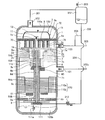
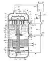
- FIG. 1 is a refrigerant circuit diagram of a refrigeration cycle apparatus according to Embodiment 1 of the present invention. It is a schematic longitudinal cross-sectional view of the whole structure of the scroll compressor which comprises the refrigerating-cycle apparatus which concerns on Embodiment 2 of this invention.
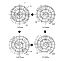
- FIG. 4 is a schematic horizontal sectional view of the compression mechanism of FIG. 3; It is a schematic longitudinal cross-sectional view of the whole structure of the scroll compressor which comprises the refrigerating-cycle apparatus which concerns on Embodiment 3 of this invention.
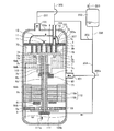
- FIG. 1 is a schematic vertical cross-sectional view of the overall configuration of a scroll compressor that constitutes a refrigeration cycle apparatus according to Embodiment 1 of the present invention.
- Arrows in FIG. 1 indicate flows of refrigerant and oil. The same applies to the figures described later.
- the scroll compressor 100 has a compression mechanism 3, an electric mechanism 110, and other components.
- the scroll compressor 100 has a configuration in which these components are housed inside a container 100a constituting an outer shell.
- the compression mechanism 3 and the motor-driven mechanism 110 are connected via the rotary shaft 6, and the rotational force generated by the motor-driven mechanism 110 is transmitted to the compression mechanism 3 via the rotary shaft 6.
- the refrigerant is adapted to be compressed.
- the container 100a is provided with a suction pipe 101 for suctioning the refrigerant, a discharge pipe 102 for discharging the refrigerant, and an injection pipe 103 for suctioning an injection refrigerant described later into the compression mechanism 3 .
- the injection pipe 103 is for introducing a refrigerant into the compression mechanism 3 in the container 100 a separately from the suction pipe 101.
- the injection pipe 103 is connected to an injection port 7 a formed in a frame 7 described later.
- a frame 7 and a sub-frame 9 for fixing the compression mechanism 3 to the container 100a are disposed inside the container 100a.
- the frame 7 is disposed on the upper side of the electromotive mechanism 110 and on the lower side of the compression mechanism 3 and is fixed to the inner circumferential surface of the container 100a by shrink fitting, welding or the like.
- a communication channel 7 c for guiding the refrigerant flowing from the suction pipe 101 into the compression mechanism 3 is formed in the frame 7.
- the sub-frame 9 is disposed below the motor-driven mechanism 110, and is fixed to the inner circumferential surface of the container 100a by shrink fitting, welding or the like via the sub-frame plate 9a.
- a displacement pump 111 is attached to the lower end of the sub-frame 9 so as to axially support the rotary shaft 6 at the upper end face.
- the rotation shaft 6 is provided with an in-shaft flow passage 6 d.
- the in-shaft flow path 6d has an oil hole 6da axially extending in the central portion of the rotary shaft 6, and a plurality of oil supply holes 6db communicating radially with the oil hole 6da.
- the oil supply hole 6db is formed at a position facing each of the rocking bearing 2c, the main bearing 7b, and the auxiliary bearing 10, and is a sliding portion of the rotating shaft 6, and supplied from the positive displacement pump 111 to each of these bearings.
- To supply the The oil supplied to the rocking bearing 2c and the like is returned from the bearing operation space 73 described later through the oil return pipe 113 to the oil reservoir 100b.
- One end of the suction pipe 111a is connected to the positive displacement pump 111, and the other end of the suction pipe 111a is immersed in the oil reservoir 100b to suck up the oil in the oil reservoir 100b to flow the inner flow passage 6d of the rotating shaft 6 Supply to
- the compression mechanism 3 has a fixed scroll 1 and an oscillating scroll 2.
- the fixed scroll 1 is fixed to the frame 7.
- the swing scroll 2 is disposed below the fixed scroll 1 and swingably supported by an eccentric shaft portion 6 a described later of the rotation shaft 6.
- the fixed scroll 1 has a fixed base plate 1a and a fixed scroll 1b provided upright on one surface of the fixed base plate 1a.
- the rocking scroll 2 has a rocking bed plate 2a and a rocking scroll 2b provided upright on one surface of the rocking bed plate 2a.
- the fixed scroll 1 and the rocking scroll 2 are disposed in the container 100 a in a symmetrical spiral shape in which the fixed scroll 1 b and the rocking scroll 2 b are meshed in the reverse phase with respect to the rotation center of the rotating shaft 6 There is.
- a compression chamber 8 is formed between the fixed scroll 1b and the swinging scroll 2b, the volume of which decreases as it goes from the radially outer side to the inner side as the rotary shaft 6 rotates.
- a structure portion having a symmetrical spiral shape in which the rocking scroll 2b and the fixed scroll 1b are combined in particular is referred to as a spiral portion 3a.
- a discharge port 1c communicating with the compression chamber 8 is formed through the fixed base plate 1a of the fixed scroll 1 and a discharge valve 11 is provided in the discharge port 1c. And the discharge muffler 12 is attached so that this discharge port 1c may be covered.
- a cylindrical boss 2d is formed substantially at the center of the surface (hereinafter referred to as the back surface) opposite to the surface on which the rocking scroll 2b is formed in the rocking base plate 2a of the rocking scroll 2.
- a rocking bearing 2c is disposed inside the boss 2d, and an eccentric shaft 6a formed on the upper end of the rotary shaft 6 is fitted inside the rocking bearing 2c.
- the rotating shaft 6 is composed of an eccentric shaft 6 a at the upper part of the rotating shaft 6, a main shaft 6 b, and a sub shaft 6 c at the lower part of the rotating shaft 6.
- the eccentric shaft 6a is rotatably fitted to the boss 2d of the rocking scroll 2 via the rocking bearing 2c, and slides on the rocking bearing 2c via an oil film of oil.
- the rocking bearing 2c is fixed in the boss portion 2d by press-fitting a bearing material such as a copper-lead alloy used for a sliding bearing.
- the rocking scroll 2 is rocked by the rotation of the rotary shaft 6.
- the main shaft portion 6b is rotatably fitted to the main bearing 7b provided on the frame 7, and slides with the main bearing 7b via an oil film of oil.
- the main bearing 7b is fixed to the frame 7 by press-fitting or the like of a bearing material such as a copper-lead alloy used for a slide bearing.
- the central portion of the sub-frame 9 is provided with a sub bearing 10 composed of a ball bearing, and supports the rotating shaft 6 in the radial direction below the electric mechanism 110.
- the auxiliary bearing 10 may have another bearing configuration other than the ball bearing.
- the countershaft 6 c of the rotating shaft 6 is fitted to the subbearing 10 and slides on the subbearing 10.
- the axial centers of the main shaft portion 6 b and the auxiliary shaft portion 6 c coincide with the axial center of the rotation shaft 6.
- the space in the container 100a is defined as follows. Of the internal space of the container 100a, it is formed by the inner wall of the recess formed on the upper surface of the frame 7 and the outermost peripheral surface of the structure portion in which the swinging scroll 2b of the compression mechanism 3 and the fixed scroll 1b are engaged. This space is called a spiral installation space 70. Further, the space below the frame 7 in the internal space of the container 100 a is referred to as a shell suction space 71.
- the shell suction space 71 is a low pressure space filled with the suction refrigerant introduced from the suction pipe 101.
- a shell discharge space 72 the space on the discharge pipe 102 side from the fixed base plate 1 a of the compression mechanism 3 is referred to as a shell discharge space 72.
- a space formed in the frame 7 for accommodating the rocking bearing 2c and rotating the rocking bearing 2c is referred to as a bearing operation space 73.
- an inner space between the upper end of the rotary shaft 6 and the swing base plate 2 a of the swing scroll 2 and an inner space of the boss 2 d is referred to as a boss inner space 74.
- the electromotive mechanism 110 has a motor stator 110a and a motor rotor 110b.
- the motor stator 110a is connected by a lead wire (not shown) to a glass terminal (not shown) present between the frame 7 and the motor stator 110a in order to obtain power from the outside.
- the motor rotor 110 b is fixed to the rotating shaft 6 by shrink fitting or the like. Further, in order to balance the entire rotation system of the scroll compressor 100, the first balance weight 60 is fixed to the rotation shaft 6, and the second balance weight 61 is fixed to the motor rotor 110b. There is.
- oil flows from the suction pipe 101 together with the refrigerant.
- the oil is used for the purpose of improving the lubricity of the sliding portion and the sealing function for suppressing the gap leak of the compression chamber 8.
- An oil separator 202 is disposed downstream of the scroll compressor 100 to separate oil from the refrigerant discharged from the scroll compressor 100.
- a refrigeration cycle apparatus 300 including the scroll compressor 100 and the oil separator 202 will be described.
- FIG. 2 is a refrigerant circuit diagram of the refrigeration cycle apparatus according to Embodiment 1 of the present invention.
- a scroll compressor 100 In the refrigeration cycle apparatus 300, a scroll compressor 100, an oil separator 202, a condenser 301, a decompression device 302 including an expansion valve or a capillary tube, and an evaporator 303 are sequentially connected by refrigerant piping.
- a main circuit 300a through which the refrigerant circulates is provided.
- the refrigeration cycle apparatus 300 further includes an injection circuit 305 separated from between the condenser 301 and the pressure reducing device 302 and connected to the injection pipe 103 of the scroll compressor 100.
- the injection circuit 305 is provided with an expansion valve 304 as a flow rate adjustment valve, so that the flow rate to be injected can be adjusted.
- the oil separator 202 is connected to the discharge pipe 102 of the scroll compressor 100 by a circuit 201.
- the opening degree of the pressure reducing device 302, the opening degree of the expansion valve 304, and the rotation speed of the scroll compressor 100 are controlled by a control device (not shown).
- a four-way valve may be further provided in the refrigeration cycle apparatus 300 to switch the flow direction of the refrigerant in the reverse direction.
- the condenser 301 installed downstream of the scroll compressor 100 is the indoor unit side and the evaporator 303 is the outdoor unit side
- the heating operation is performed
- the condenser 301 is the outdoor unit side and the evaporator 303 is the indoor unit side. If it does, it will be cooling operation.
- the oil in the oil separator 202 is returned to the scroll compressor 100 into two branches downstream of the oil return circuit 206, and the outlet of one oil return circuit 204 is the container 100a.
- This configuration is in direct communication with the positive displacement pump 111 instead of the oil reservoir 100 b at the bottom.
- the outlet of the other oil return circuit 205 is in communication with the injection circuit 305.
- the oil returned from the oil return circuit 204 mainly lubricates the bearings, and the oil returned from the oil return circuit 205 improves the sealability of the compression mechanism 3.
- the oil return circuit 204 corresponds to a first oil return circuit of the present invention
- the oil return circuit 205 corresponds to a second oil return circuit of the present invention.
- a pipe constituting the oil return circuit 204 is extended upstream of a branch point with the oil return circuit 205 and connected to the bottom of the oil separator 202. . Further, the downstream end of the pipe constituting the oil return circuit 204 is configured to penetrate the container 100 a and be connected to the suction port of the positive displacement pump 111. As a specific configuration of the oil return circuit 205, the upstream end of the pipe constituting the oil return circuit 205 is connected to the pipe of the oil return circuit 204, and the downstream end is connected to the pipe of the injection circuit 305.
- a pump chamber (not shown) in the positive displacement pump 111 is first connected to the low pressure suction pipe 111a, and its volume is expanded as it rotates to suck oil from the suction pipe 111a, and then the suction pipe 111a Close the connection with Next, the pump chamber (not shown) is connected to the high pressure oil return circuit 204 piping, and the volume is further expanded to suck in the oil of the oil return circuit 204, and then the connection with the oil return circuit 204 piping close up.
- the pump chamber (not shown) is connected to the in-shaft channel 6d, and the volume is reduced, and the sucked oil is discharged to the in-shaft channel 6d to close the connection with the in-shaft channel 6d and return first.
- the positive displacement pump 111 a positive displacement pump configured to operate in this manner can be used.
- the refrigerant discharged from the scroll compressor 100 flows into the oil separator 202.
- the refrigerant and the oil mixed in the refrigerant are separated, and the separated refrigerant is cooled by the condenser 301.
- the refrigerant cooled by the condenser 301 is reduced in pressure by the pressure reducing device 302 and then heated by the evaporator 303 to become a refrigerant gas.
- the refrigerant gas flowing out of the evaporator 303 returns to the scroll compressor 100.
- the refrigerant returning to the scroll compressor 100 flows into the container 100 a from the suction pipe 101.
- the low-pressure refrigerant flowing from the suction pipe 101 into the shell suction space 71 in the container 100 a passes through the communication flow path 7 c formed in the frame 7 and flows into the spiral installation space 70.
- the refrigerant flowing into the swirl installation space 70 mixes with the refrigerant flowing from the injection pipe 103 via the injection port 7 a. Then, the mixed refrigerant is drawn into the compression chamber 8 along with the relative swing operation of the fixed scroll 1 b of the fixed scroll 1 and the swing scroll 2 b of the swing scroll 2.
- the sucked refrigerant is boosted from low pressure to high pressure by the geometric volume change of the compression chamber 8 accompanying the operation of the oscillating scroll 2.
- the discharge valve 11 is opened, and the refrigerant is discharged to the shell discharge space 72 from the discharge port 1c installed in the fixed scroll 1. . Thereafter, the discharged refrigerant is discharged from the discharge pipe 102 via the shell discharge space 72 as a high pressure refrigerant to the circuit 201 outside the compressor.
- the refrigerant of the circuit 201 discharged from the scroll compressor flows into the oil separator 202, separates the oil contained in the refrigerant, and then flows out to the circuit 203 directed to the condenser 301.
- part of the refrigerant cooled by the condenser 301 flows into the injection circuit 305, and flows through the expansion valve 304 into the injection pipe 103 of the scroll compressor 100.
- the liquid or two-phase injection refrigerant flowing into the injection pipe 103 passes through the swirl installation space 70 and flows into the suction chamber in the compression mechanism 3.
- the oil that has flowed out of the scroll compressor 100 is separated by the oil separator 202, passes through the oil return circuit 206, and is supplied to the scroll compressor 100.
- the oil return circuit 206 the oil return circuit 204 is connected to the suction port of the positive displacement pump 111. Therefore, the oil stored in the oil separator 202 is supplied from the suction port of the positive displacement pump 111 to the in-shaft flow path 6 d of the rotating shaft 6. Then, the oil supplied to the in-shaft flow path 6d is supplied to the sliding portions such as the rocking bearing 2c, the main bearing 7b, and the sub bearing 10.
- a portion of the oil supplied to the sliding portion is supplied to a bearing operation space 73 installed downstream of the rocking bearing 2c and the main bearing 7b. Thereafter, the oil supplied to the bearing operation space 73 is stored in the oil reservoir 100b of the container 100a through the oil return pipe 113. Part of the oil stored in the oil reservoir 100b is sucked from the suction pipe 111a by the operation of the positive displacement pump 111 by the rotation of the rotary shaft 6, and is supplied again to the sliding portion. Further, a part of the oil stored in the oil reservoir 100b is wound up by the flow of the refrigerant flowing from the suction pipe 101, flows into the compression mechanism 3 through the communication flow path 7c, and then to the outside of the scroll compressor 100. And flow out.
- the downstream side of the oil return circuit 205 is connected to the injection circuit 305. Therefore, the oil stored in the oil separator 202 is supplied from the oil return circuit 205 to the injection refrigerant of the injection circuit 305 and flows into the spiral installation space 70 of the compression mechanism 3 together with the injection refrigerant. The oil that has flowed into the swirl installation space 70 flows into the compression chamber 8 and flows out of the scroll compressor 100.
- the positive displacement pump 111 is configured such that the oil return circuit 206 from the oil separator 202 is branched into two, and one oil return circuit 204 is configured by the positive displacement pump instead of the oil reservoir 100 b. , And the other oil return circuit 205 is in communication with the injection circuit 305. Since the displacement pump also increases the discharge amount of oil as the rotational speed increases, the amount of oil returned from the oil separator 202 to the in-shaft flow path 6d via the oil return circuit 204 during the high speed operation is a low speed It can be relatively increased compared to when driving.
- the sealability of the compression mechanism 3 can be improved by positively returning oil from the oil separator 202 to the injection circuit 305.
- the second embodiment relates to a configuration in which the connection position of the injection pipe 103 is changed in the first embodiment shown in FIG.
- the second embodiment will be described focusing on the difference from the first embodiment.
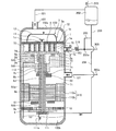
- FIG. 3 is a schematic vertical cross-sectional view of the entire configuration of a scroll compressor that constitutes a refrigeration cycle apparatus according to Embodiment 2 of the present invention.
- FIG. 4 is a horizontal schematic cross-sectional view of the compression mechanism of FIG.
- the phases of 0 deg, 90 deg, 180 deg and 270 deg described in FIG. 4 indicate the rotational phase of the compression mechanism.
- the injection pipe 103 penetrates the container 100a from the outside and is inserted into the inside, and is connected to the injection port 207 formed in the fixed base plate 1a.
- the outlet 103a of the injection pipe 103 is communicated with the inside of the compression mechanism 3, and the injection refrigerant flows into the compression chamber 8 in the middle of the compression process, in other words, the intermediate pressure space 75 where the inside is an intermediate pressure.
- the intermediate pressure refers to the pressure between the suction pressure and the discharge pressure.
- the amount of oil flowing from the oil separator 202 to the injection pipe 103 can be suppressed as compared with the first embodiment.
- the pressure difference with the outlet 103a of the Therefore, even if the injection refrigerant flow rate is equal, the amount of oil flowing from the oil separator 202 to the injection pipe 103 can be suppressed.
- the second embodiment compared to the first embodiment, it is possible to suppress the excessive oil supply from the injection pipe 103 to the compression mechanism 3 even under the operating condition where the high / low pressure difference is large and reduce the oil outflow. It becomes. Therefore, it is possible to provide a scroll compressor having high performance and reliability in a wide operating range.
- a resistance element is further provided to the configuration of the first embodiment shown in FIG.
- the configuration in which the third embodiment is different from the first embodiment will be mainly described.
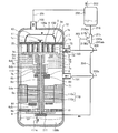
- FIG. 5 is a schematic vertical cross-sectional view of the overall configuration of a scroll compressor that constitutes a refrigeration cycle apparatus according to a third embodiment of the present invention.
- the third embodiment has a configuration in which a capillary tube 210 is installed as a resistance element on the downstream side of the connection portion 205 a with the oil return circuit 205 in the injection circuit 305.
- the capillary tube 210 reduces the flow rate of the injection refrigerant flowing from the injection circuit 305 into the compression mechanism 3.
- the same effect as that of the first embodiment can be obtained, and the following effect can be obtained by disposing the capillary tube 210 downstream of the connection portion 205a with the oil return circuit 205 in the injection circuit 305. . That is, the flow rate of the injection refrigerant flowing into the scroll compressor 100 can be reduced after the installation as compared to before the installation of the capillary tube 210. For this reason, as in the case of the second embodiment, it is possible to suppress excessive refueling to the compression mechanism 3.
- the resistance element is constituted by the capillary tube 210
- the flow velocity is increased in the capillary tube 210, so that the refrigerant passing through the injection circuit 305 and the oil flowing from the oil return circuit 205 into the injection circuit 305 are convectively stirred. it can. Therefore, the refrigerant and the oil can be mixed in a more uniform mixed state and then supplied to the spiral portion 3 a of the compression mechanism 3.
- the sealability of the compression mechanism 3 can be further improved as compared with the first and second embodiments. Therefore, the third embodiment can provide the scroll compressor 100 having higher performance than the first embodiment and the second embodiment.
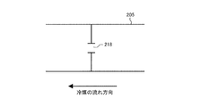
- capillary tube 210 was mentioned as an example and demonstrated as a resistance element here, you may use fixed resistance like the strainer 217 as shown, for example in FIG. 6 or the orifice hole 218 as shown in FIG. . Further, as shown in FIG. 8 below, a variable resistor such as a flow rate adjustment valve may be used.
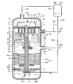
- FIG. 8 is a schematic vertical cross-sectional view of the entire configuration of a modification of the scroll compressor that constitutes the refrigeration cycle apparatus according to Embodiment 3 of the present invention.
- a flow rate adjusting valve 211 configured of, for example, an expansion valve capable of adjusting the opening degree is used as the resistance element.
- the amount of oil flowing from the oil separator 202 to the positive displacement pump 111 via the oil return circuit 204 is returned by throttling the opening degree of the flow rate adjustment valve 211. It is possible to increase relative to the oil circuit 205 side. Further, at the time of low speed operation, by increasing the opening degree of the flow rate adjustment valve 211, it is possible to increase the amount of oil flowing from the injection circuit 305 into the compression mechanism 3 and improve the sealability of the compression mechanism 3.
- the fourth embodiment has a configuration in which a resistance element is further provided to the oil return circuit 204 of the first embodiment shown in FIG. In the following, the fourth embodiment will be described focusing on a configuration different from the first embodiment.
- FIG. 9 is a schematic longitudinal sectional view of the entire configuration of a scroll compressor that constitutes a refrigeration cycle apparatus according to a fourth embodiment of the present invention.
- the capillary 212 is installed in the oil return circuit 204 as a resistance element.
- the capillary 212 is for depressurizing the oil flowing from the oil separator 202 into the injection circuit 305.
- the same effect as that of the first embodiment can be obtained, and by providing the capillary tube 212 in the oil return circuit 204, the following operation and effect can be obtained. That is, by installing the capillary tube 212 in the oil return circuit 204, the high-pressure oil supplied from the oil separator 202 can be supplied to the positive displacement pump 111 in a state where the pressure is sufficiently reduced by the capillary tube 212. Therefore, the pressure difference between the low pressure oil supplied from the suction pipe 111a to the positive displacement pump 111 and the high pressure oil supplied from the oil return circuit 204 to the positive displacement pump 111 can be reduced.
- the pressure difference between the low pressure oil supplied from the suction pipe 111a to the positive displacement pump 111 and the oil supplied from the oil return circuit 204 to the positive displacement pump 111 is temporarily large, the following problems occur. That is, the oil supplied from the oil return circuit 204 to the positive displacement pump 111 flows back through the suction pipe 111a to the oil reservoir 100b of the container 100a due to the pressure difference. That is, the oil supplied from the oil return circuit 204 to the positive displacement pump 111 does not flow into the in-shaft flow path 6d, but flows into the oil reservoir 100b. In this case, the amount of oil supplied to the sliding portion such as a bearing is reduced.
- the fourth embodiment can provide a scroll compressor having higher reliability than the first embodiment.
- the capillary tube 212 is used as the resistance element
- the case is not limited to the capillary tube.
- a fixed resistance such as a strainer or an orifice may be used, or a variable resistance such as a flow control valve may be used. Even when these resistors are used, similar effects can be obtained.
- Embodiment 5 has a configuration in which a resistance element is further provided to the oil return circuit 205 of the first embodiment shown in FIG. In the following, the fifth embodiment will be described focusing on a configuration different from the first embodiment.
- FIG. 10 is a schematic vertical cross-sectional view of the overall configuration of the scroll compressor that constitutes the refrigeration cycle apparatus according to Embodiment 5 of the present invention.
- the capillary tube 213 is installed in the oil return circuit 205 as a resistance element.
- the capillary tube 213 is for reducing the amount of oil flowing into the injection circuit 305.
- the capillary tube 210 is installed in the injection circuit 305. Therefore, in the third embodiment, the flow rate of the refrigerant as well as the oil is reduced.
- Embodiment 5 since the capillary tube 213 is provided in the oil return circuit 205, the amount of oil itself supplied to the injection pipe 103 can be reduced.
- the same effect as that of the first embodiment can be obtained, and by providing the capillary tube 213 in the oil return circuit 205, the following effect can be obtained. That is, it is possible to suppress the excessive oil supply from the oil return circuit 205 to the compression mechanism 3 while securing the flow rate of the refrigerant supplied from the injection pipe 103. As a result, while efficiently cooling the refrigerant gas in the compression process in the compression mechanism 3 by the injection refrigerant, it is possible to suppress an increase in oil outflow from the compression mechanism 3 due to excessive oil supply. Therefore, it is possible to provide a scroll compressor having higher reliability than the case of the first embodiment.
- the capillary tube 213 is used as the resistance element
- the case is not limited to the capillary tube.
- a fixed resistance such as a strainer or an orifice may be used, or a variable resistance such as a flow control valve may be used. Even when these resistors are used, similar effects can be obtained.
- the sixth embodiment has a configuration in which a gas-liquid separator is further installed in the first embodiment shown in FIG. In the following, the sixth embodiment will be described focusing on a configuration different from the first embodiment.
- FIG. 11 is a schematic vertical cross-sectional view of the entire configuration of the scroll compressor that constitutes the refrigeration cycle apparatus according to Embodiment 6 of the present invention.
- the gas-liquid separator 214 is installed at a branch point between the oil return circuit 204 and the oil return circuit 205.
- the gas-liquid separator 214 is connected to the separation vessel 214a, the inlet pipe 214b connected to the separation vessel 214a, the outlet pipe 214c connected to the bottom of the separation vessel 214a, and the side of the separation vessel 214a.
- an outlet pipe 214d The outlet pipe 214c corresponds to a first outlet pipe of the present invention, and the outlet pipe 214d corresponds to a second outlet pipe of the present invention.
- the outlet pipe 214 c is connected to the oil return circuit 204, and the outlet pipe 214 d is connected to the oil return circuit 205.
- the refrigerant and the oil are separated as described above, and the separated oil flows into the gas-liquid separator 214.
- a refrigerant containing oil may flow out of the oil separator 202 instead of a single oil.
- a gas-liquid separator 214 is provided at a branch point of the oil return circuit 204 and the oil return circuit 205 so that oil is supplied to the oil return circuit 204 with priority over the oil return circuit 205.
- the oil is separated from the refrigerant flowing from the inlet pipe 214b, and the separated oil is accumulated at the bottom of the separation container 214a.
- the oil accumulated at the bottom of the separation container 214a preferentially flows out of the outlet piping 214c connected to the bottom surface of the separation container 214a as compared with the outlet piping 214d connected to the side surface of the separation container 214a.
- the same effects as those of the first embodiment can be obtained, and the gas-liquid separator 214 is provided at the branch point of the oil return circuit 204 and the oil return circuit 205.
- oil is preferentially supplied to the oil return circuit 204. Therefore, the amount of oil returned to the positive displacement pump 111 can be secured.
- damage to the sliding portion due to insufficient oil supply can be suppressed, and a scroll compressor with higher reliability than in the case of the first embodiment can be provided.
- the gas-liquid separator 214 in which a plurality of pipes are connected to the separation container 214a is described as an example, but as shown in FIG. 12, a T-shaped pipe is used. It is good.
- FIG. 12 is a schematic vertical cross-sectional view of the entire configuration of a modified example of the scroll compressor that constitutes the refrigeration cycle apparatus according to Embodiment 6 of the present invention.
- a T-shaped tube 215 is provided as a gas-liquid separator.
- the T-shaped tube 215 is vertically connected to a vertical tube 215a which extends vertically and whose upper end opening is the inflow port 215aa and lower end opening is the outflow port 215ab, and is horizontally connected to the vertical pipe 215a and whose open end is the outflow port 215ba And a tube 215b.
- the inlet 215 aa communicates with the bottom of the oil separator 202, the outlet 215 ab communicates with the oil return circuit 204, and the outlet 215 ba communicates with the oil return circuit 205.
- the outlet 215ab corresponds to the first outlet of the present invention, and the outlet 215ba corresponds to the second outlet of the present invention.
- Embodiment 7 The seventh embodiment is intended to improve the lubrication of the bearing.
- the seventh embodiment will be described below focusing on the difference from the first embodiment.
- FIG. 13 is a schematic vertical cross-sectional view of the overall configuration of a scroll compressor that constitutes a refrigeration cycle apparatus according to a seventh embodiment of the present invention.
- the seventh embodiment has a configuration in which a through hole 216 communicating the boss internal space 74 and the bearing operation space 73 is provided in the boss 2d of the first embodiment shown in FIG.
- the same effects as those of the first embodiment can be obtained, and the following effects can be obtained by providing the through holes 216 in the boss 2 d.
- the pressure in the oil return circuit 204 is high, the installation space of the positive displacement pump 111 is low. For this reason, when high-pressure oil in the oil return circuit 204 is supplied to the low-pressure positive displacement pump 111, the pressure drops rapidly, and the refrigerant gas dissolved in the oil may foam. The refrigerant gas thus foamed rises in the oil hole 6da of the rotating shaft 6, and flows out from the upper end of the oil hole 6da to the boss internal space 74.
- the seventh embodiment can provide a scroll compressor having higher reliability than the first embodiment.
- the refrigeration cycle apparatus may be configured by appropriately combining the characteristic configurations of the respective embodiments.
- the through holes 216 may be provided in the boss 2 d of the scroll compressor 100 of FIG. 3 by combining the second embodiment and the seventh embodiment.
- Reference Signs List 1 fixed scroll, 1a fixed base plate, 1b fixed scroll, 1c discharge port, 2 swing scroll, 2a swing base plate, 2b swing scroll, 2c swing bearing, 2d boss portion, 3 compression mechanism, 3a swirl Parts, 6 rotation shafts, 6a eccentric shaft parts, 6b main shaft parts, 6c sub shaft parts, 6d axial flow channels, 6da oil holes, 6db oil holes, 7 frames, 7a injection ports, 7b main bearings, 7c communication flow paths, 8 compression chamber, 9 sub frame, 9a sub frame plate, 10 sub bearing, 11 discharge valve, 12 discharge muffler, 20 oil return piping, 60 first balance weight, 61 second balance weight, 70 spiral installation space, 71 shell suction Space, 72 shell discharge space, 73 bearing operation space, 74 boss internal space, 75 medium pressure space, 00 scroll compressor, 100a container, 100b oil reservoir, 101 suction pipe, 102 discharge pipe, 103 injection pipe, 103a outlet, 110 motor mechanism, 110a motor stator, 110b motor rotor, 111
Landscapes
- Engineering & Computer Science (AREA)
- Physics & Mathematics (AREA)
- Mechanical Engineering (AREA)
- Thermal Sciences (AREA)
- General Engineering & Computer Science (AREA)
- Rotary Pumps (AREA)
- Applications Or Details Of Rotary Compressors (AREA)
Abstract
Un compresseur à spirale constituant une partie de ce dispositif à cycle frigorifique de la présente invention comprend une pompe à déplacement positif qui fournit une huile de stockage dans une partie inférieure de récipient à une partie coulissante d'un arbre rotatif par l'intermédiaire d'un trajet d'écoulement intra-arbre formé dans l'arbre rotatif. Le dispositif à cycle frigorifique comprend un circuit d'huile de retour pour renvoyer l'huile séparée par un dispositif de séparation d'huile au compresseur à spirale. Le côté aval du circuit d'huile de retour est divisé en deux branches, une première sortie de circuit d'huile de retour dans une branche communiquant avec la pompe à déplacement positif, et une seconde sortie de circuit d'huile de retour dans l'autre branche communiquant avec un circuit d'injection.
Priority Applications (3)
| Application Number | Priority Date | Filing Date | Title |
|---|---|---|---|
| JP2019532242A JP6704526B2 (ja) | 2017-07-25 | 2017-07-25 | 冷凍サイクル装置 |
| CN201780090746.8A CN110914607B (zh) | 2017-07-25 | 2017-07-25 | 制冷循环装置 |
| PCT/JP2017/026787 WO2019021360A1 (fr) | 2017-07-25 | 2017-07-25 | Dispositif à cycle frigorifique |
Applications Claiming Priority (1)
| Application Number | Priority Date | Filing Date | Title |
|---|---|---|---|
| PCT/JP2017/026787 WO2019021360A1 (fr) | 2017-07-25 | 2017-07-25 | Dispositif à cycle frigorifique |
Publications (1)
| Publication Number | Publication Date |
|---|---|
| WO2019021360A1 true WO2019021360A1 (fr) | 2019-01-31 |
Family
ID=65039533
Family Applications (1)
| Application Number | Title | Priority Date | Filing Date |
|---|---|---|---|
| PCT/JP2017/026787 Ceased WO2019021360A1 (fr) | 2017-07-25 | 2017-07-25 | Dispositif à cycle frigorifique |
Country Status (3)
| Country | Link |
|---|---|
| JP (1) | JP6704526B2 (fr) |
| CN (1) | CN110914607B (fr) |
| WO (1) | WO2019021360A1 (fr) |
Cited By (2)
| Publication number | Priority date | Publication date | Assignee | Title |
|---|---|---|---|---|
| WO2021140566A1 (fr) * | 2020-01-07 | 2021-07-15 | 三菱電機株式会社 | Dispositif à cycle frigorifique |
| WO2021210064A1 (fr) * | 2020-04-14 | 2021-10-21 | 三菱電機株式会社 | Unité de source de chaleur, dispositif à cycle de réfrigération et réfrigérateur |
Citations (8)
| Publication number | Priority date | Publication date | Assignee | Title |
|---|---|---|---|---|
| JPH05118675A (ja) * | 1991-10-29 | 1993-05-14 | Hitachi Ltd | マルチタイプ冷凍機、およびこの冷凍機用の油分離器 |
| JPH06229634A (ja) * | 1993-02-01 | 1994-08-19 | Sanyo Electric Co Ltd | 冷凍装置 |
| JPH06317267A (ja) * | 1993-04-30 | 1994-11-15 | Sanyo Electric Co Ltd | スクロール圧縮機 |
| JP2010216691A (ja) * | 2009-03-16 | 2010-09-30 | Hitachi Appliances Inc | 冷凍サイクル装置 |
| JP2012242081A (ja) * | 2011-05-19 | 2012-12-10 | Lg Electronics Inc | 空気調和機 |
| JP2012247134A (ja) * | 2011-05-27 | 2012-12-13 | Sanyo Electric Co Ltd | 超低温冷凍装置 |
| WO2015173939A1 (fr) * | 2014-05-15 | 2015-11-19 | 三菱電機株式会社 | Unité de réfrigération |
| WO2016079859A1 (fr) * | 2014-11-20 | 2016-05-26 | 三菱電機株式会社 | Appareil à cycle de réfrigération |
Family Cites Families (14)
| Publication number | Priority date | Publication date | Assignee | Title |
|---|---|---|---|---|
| JP2003166472A (ja) * | 2001-11-30 | 2003-06-13 | Sanyo Electric Co Ltd | 圧縮機 |
| DE602004028767D1 (de) * | 2003-09-30 | 2010-09-30 | Sanyo Electric Co | Rotationsverdichter, Klimaanlage für ein Fahrzeug und Wassererhitzer, die den Verdichter beinhalten |
| JP2005240637A (ja) * | 2004-02-25 | 2005-09-08 | Mitsubishi Heavy Ind Ltd | ガス圧縮ユニット |
| JP2006291799A (ja) * | 2005-04-08 | 2006-10-26 | Matsushita Electric Ind Co Ltd | 密閉型ロータリ圧縮機 |
| KR100864754B1 (ko) * | 2005-11-28 | 2008-10-22 | 엘지전자 주식회사 | 스크롤 압축기의 오일 공급 구조 |
| CN100529406C (zh) * | 2007-11-09 | 2009-08-19 | 广东美芝制冷设备有限公司 | 壳体低压的旋转式压缩机及其冷媒、回油的控制方式和应用 |
| KR101487822B1 (ko) * | 2008-11-14 | 2015-01-29 | 엘지전자 주식회사 | 밀폐형 압축기 및 이를 적용한 냉동기기 |
| JP2011058431A (ja) * | 2009-09-10 | 2011-03-24 | Toshiba Carrier Corp | 密閉型回転式圧縮機および冷凍サイクル装置 |
| CN103486773B (zh) * | 2013-08-30 | 2015-09-09 | 青岛海信日立空调系统有限公司 | 基于管壳式换热器的回油控制系统 |
| JP6242235B2 (ja) * | 2014-02-20 | 2017-12-06 | 三菱電機株式会社 | 熱源ユニット及び冷凍サイクル装置 |
| JP6164427B2 (ja) * | 2014-03-28 | 2017-07-19 | 株式会社富士通ゼネラル | ロータリ圧縮機 |
| JP2016102639A (ja) * | 2014-11-28 | 2016-06-02 | ダイキン工業株式会社 | ロータリ型圧縮機、および、それを用いた空気調和機 |
| JP6495048B2 (ja) * | 2015-02-26 | 2019-04-03 | 三菱重工サーマルシステムズ株式会社 | 冷凍サイクルの油戻し回路および油戻し方法 |
| JP6472510B2 (ja) * | 2015-04-24 | 2019-02-20 | 三菱電機株式会社 | 冷凍空調装置 |
-
2017
- 2017-07-25 WO PCT/JP2017/026787 patent/WO2019021360A1/fr not_active Ceased
- 2017-07-25 CN CN201780090746.8A patent/CN110914607B/zh active Active
- 2017-07-25 JP JP2019532242A patent/JP6704526B2/ja not_active Expired - Fee Related
Patent Citations (8)
| Publication number | Priority date | Publication date | Assignee | Title |
|---|---|---|---|---|
| JPH05118675A (ja) * | 1991-10-29 | 1993-05-14 | Hitachi Ltd | マルチタイプ冷凍機、およびこの冷凍機用の油分離器 |
| JPH06229634A (ja) * | 1993-02-01 | 1994-08-19 | Sanyo Electric Co Ltd | 冷凍装置 |
| JPH06317267A (ja) * | 1993-04-30 | 1994-11-15 | Sanyo Electric Co Ltd | スクロール圧縮機 |
| JP2010216691A (ja) * | 2009-03-16 | 2010-09-30 | Hitachi Appliances Inc | 冷凍サイクル装置 |
| JP2012242081A (ja) * | 2011-05-19 | 2012-12-10 | Lg Electronics Inc | 空気調和機 |
| JP2012247134A (ja) * | 2011-05-27 | 2012-12-13 | Sanyo Electric Co Ltd | 超低温冷凍装置 |
| WO2015173939A1 (fr) * | 2014-05-15 | 2015-11-19 | 三菱電機株式会社 | Unité de réfrigération |
| WO2016079859A1 (fr) * | 2014-11-20 | 2016-05-26 | 三菱電機株式会社 | Appareil à cycle de réfrigération |
Cited By (8)
| Publication number | Priority date | Publication date | Assignee | Title |
|---|---|---|---|---|
| WO2021140566A1 (fr) * | 2020-01-07 | 2021-07-15 | 三菱電機株式会社 | Dispositif à cycle frigorifique |
| JPWO2021140566A1 (fr) * | 2020-01-07 | 2021-07-15 | ||
| CN114846283A (zh) * | 2020-01-07 | 2022-08-02 | 三菱电机株式会社 | 制冷循环装置 |
| JP7292428B2 (ja) | 2020-01-07 | 2023-06-16 | 三菱電機株式会社 | 冷凍サイクル装置 |
| CN114846283B (zh) * | 2020-01-07 | 2024-01-16 | 三菱电机株式会社 | 制冷循环装置 |
| WO2021210064A1 (fr) * | 2020-04-14 | 2021-10-21 | 三菱電機株式会社 | Unité de source de chaleur, dispositif à cycle de réfrigération et réfrigérateur |
| JPWO2021210064A1 (fr) * | 2020-04-14 | 2021-10-21 | ||
| JP7330367B2 (ja) | 2020-04-14 | 2023-08-21 | 三菱電機株式会社 | 熱源ユニット、冷凍サイクル装置および冷凍機 |
Also Published As
| Publication number | Publication date |
|---|---|
| JP6704526B2 (ja) | 2020-06-03 |
| CN110914607A (zh) | 2020-03-24 |
| CN110914607B (zh) | 2021-06-08 |
| JPWO2019021360A1 (ja) | 2019-12-12 |
Similar Documents
| Publication | Publication Date | Title |
|---|---|---|
| JP5695187B2 (ja) | 冷媒圧縮機及びこれを用いた冷凍サイクル装置 | |
| US20100186439A1 (en) | Fluid machine and refrigeration cycle apparatus | |
| US20130078131A1 (en) | Scroll compressor | |
| WO2018225155A1 (fr) | Compresseur à volute et appareil à cycle de réfrigération | |
| JP7253655B1 (ja) | スクロール圧縮機及び冷凍サイクル装置 | |
| JP2018165502A (ja) | 回転式圧縮機及び冷凍サイクル装置 | |
| JP2008101559A (ja) | スクロール圧縮機およびそれを用いた冷凍サイクル | |
| CN205064281U (zh) | 旋转式压缩机 | |
| WO2019021360A1 (fr) | Dispositif à cycle frigorifique | |
| US11933306B2 (en) | Scroll compressor and refrigeration cycle apparatus | |
| JP5493958B2 (ja) | 圧縮機 | |
| JP2007146864A (ja) | スクロ−ル圧縮機 | |
| JP2015152260A (ja) | 気液分離器およびそれを含む冷凍サイクル装置 | |
| JP7213382B1 (ja) | スクロール圧縮機及び冷凍サイクル装置 | |
| JP7292428B2 (ja) | 冷凍サイクル装置 | |
| JP4064325B2 (ja) | スクロ−ル圧縮機 | |
| JP4929051B2 (ja) | 密閉形スクロール圧縮機及び冷凍空調装置 | |
| JP5304679B2 (ja) | 圧縮機 | |
| JP2018009537A (ja) | スクロール圧縮機および冷凍サイクル装置 | |
| JP2013238191A (ja) | 圧縮機 | |
| JP7795124B1 (ja) | 回転式圧縮機及び冷凍装置 | |
| JP7731484B1 (ja) | スクロール圧縮機および冷凍サイクル装置 | |
| JP2010084954A (ja) | 冷凍サイクル装置 | |
| JP4016846B2 (ja) | スクロール圧縮機 | |
| JP2017218932A (ja) | 容積型圧縮機、給湯器、及び空気調和機 |
Legal Events
| Date | Code | Title | Description |
|---|---|---|---|
| 121 | Ep: the epo has been informed by wipo that ep was designated in this application |
Ref document number: 17918990 Country of ref document: EP Kind code of ref document: A1 |
|
| ENP | Entry into the national phase |
Ref document number: 2019532242 Country of ref document: JP Kind code of ref document: A |
|
| NENP | Non-entry into the national phase |
Ref country code: DE |
|
| 122 | Ep: pct application non-entry in european phase |
Ref document number: 17918990 Country of ref document: EP Kind code of ref document: A1 |